Article

Dynamic Damage Quantification of Slab Tracks—Finite Element Models on Winkler Soil and Finite-Element Boundary-Element Models on Continuous Soil

Department 7 Safety of Structures, Federal Institute of Material Research and Testing, 12200 Berlin, Germany
*
Authors to whom correspondence should be addressed.
CivilEng 2022, 3(4), 979-997; https://doi.org/10.3390/civileng3040055
Submission received: 20 June 2022 / Revised: 16 September 2022 / Accepted: 18 September 2022 / Published: 31 October 2022

Abstract

:
Train passages over intact or damaged slab tracks on different soils were calculated by two methods. The finite element method (FEM) uses a Winkler soil under the track model by adding a thin “soil layer”. The combined finite-element boundary-element method has a continuous soil model that is included by the boundary element method. The basic results are the distributions of the track (rail, track plate, and base layer) displacements along the track for a single axle load. These solutions were superposed to a complete train load and transformed to time histories. The influence of track and soil parameters was analysed. The main interest was the influence of the track damage. A gap between the track plate and base layer of different lengths was studied for changes in amplitudes and widths of deflection. A best fit to measured track displacements was found so that the track damage could be identified and quantified. The FEM model with the Winkler soil cannot be fitted to the amplitude and width with the same soil parameters. Therefore, the FEBEM model is preferable for these railway track problems.

1. Introduction

The damage of slab tracks has become an important topic for railway transportation. The Federal Institute of Material Research and Testing (BAM) has performed dynamic measurements (train passages and hammer impacts, Figure 1a,b) at some damaged, repaired, and intact slab tracks in Germany [1], whereas wheelset drop tests have been carried out at the Tongji laboratory for track identification (Figure 1c,d) [2]. The BAM measurements already give clear indication of the track damage. The present article gives some theoretical explanations for the track behaviour and aims at a quantification of one of the measured damages, a gap between the track plate and the base layer.
Slab track damage is not only a problem in Germany but particularly in China with its largest high-speed net of the world, which comprises a high portion of slab tracks. Therefore, many articles about the behaviour of damaged slab tracks come from China. Debonding of the different track layers is of strong concern [3], and the effects of temperature and train passage [4,5,6], the evolution of the damage [7,8,9,10], the behaviour [11,12,13], and the safety [14] of the damaged track, and methods for damage detection [15] have been investigated. In situ measurements of Chinese railway tracks, however, are rarely found. Moreover, damage localisation [16] and quantification in addition to damage detection [17,18] have been investigated mainly in the laboratory or by theory, so far [19].
The oldest and perhaps simplest model for the behaviour of railway tracks is a beam on a Winkler support [20]. The Winkler support [21] is a simplified model of the soil which reacts locally and linearly to a load. This simple model was dominant in track dynamics for a long time [22,23]. This has changed in the last two decades, and semianalytic methods [24], wavenumber methods [25,26,27,28], finite element methods [29], and boundary element methods [30,31], for example, are available for the calculation of ballast and slab tracks. The dynamic interaction of intact slab tracks with the soil has been analysed by these detailed methods in [32,33,34,35]. The Winkler soil model, however, is still in use for the analysis of track damage. The present article combines detailed and simplified calculations with in situ track measurements to quantify track damage and fills a gap in experimental and theoretical research on track damage. Moreover, the limited possibilities of the Winkler soil model are shown in this article.
This article consists of the following parts. Initially, the different slab track designs that have been measured are treated and presented in this article (Section 2). Next, the two theoretical methods with continuous and Winkler soil are presented in Section 3. The experimental methods follow (Section 4), and the measurement results which should be represented by the calculations are given in Section 5. Theoretical results are presented for a single axle (Section 6) and for the passage of a whole train (Section 7) to analyse the gap between the track plate and the base layer. These are the main scientific results for the civil engineering community, which are derived using both methods. The differences between the Winkler and the continuous soil methods are discussed in Section 8. In an outlook, some applications to other slab tracks (floating-slab tracks) and slab track damages are given as examples without full details (Section 9).

2. Slab Tracks and Four Measurement Sites: G, S, W, and T

BAM has investigated different slab tracks and slab track damages at three sites. The principal track elements are presented in Figure 2. A slab track with full sleepers on a track plate over a base layer was tested at Site G. This slab track has been tested twice, firstly with loss of contact between the track plate and the base layer and secondly after the repair of the damage. The quantification of this damage is the main topic of this article.
A different slab track with sleepers integrated in the track plate, a trough (base plate), and a base layer were tested at Site W, where track sections with loose sleepers and intact reference tracks were measured. A floating-slab track with an elastic layer between the track and base plate was tested at Site S for an assumed debonding between base plate and base layer. In [2], wheelset drop tests in the laboratory at Tongji University (“Site T”) have been reported, where a floating-slab track with steel springs and viscous dampers were investigated. In Section 9, the additional Sites W, S, and T are used to illustrate some additional theoretical and experimental methods.

3. Methods for the Calculation of Displacements of Railway Tracks

Two methods are presented which allow a dynamic analysis of the track. The most rigorous method is the combined three-dimensional finite-element boundary-element method. The second method is the finite element method, which uses a simplified model for the soil, the Winkler soil, which has only a local reaction to applied loads.

3.1. Finite-Element Method for a Slab Track on Winkler Soil

The finite element method is used to model the slab track. The rail is represented by beam elements, the rail pads by truss elements, and the track plate, base plate, and base layer are represented by volume elements. The underlying soil is approximated by a thin layer with material properties that yield the same displacements under a wheelset as a track on continuous soil would yield. Modelling and calculation were done within the commercial finite element software ANSYS.
The finite element method is well suited to model local specialties of the track. Local damages of the slab tracks are modelled and calculated in this contribution. The finite element method also allows for modelling different track layers (base layer, base plate, track plate) and possible gaps between these layers. This holds for the FEBEM model with continuous soil and for the FEM track model on Winkler support.

3.2. Modelling Details of the Finite-Element Slab Track

The track model shown in Figure 3 was used for the finite element method on Winkler support and the finite-element boundary-element method with continuous soil. The track plate (turquoise), the base plate (violet), the mortar between track and base plate (orange), and the Winkler support (green) are modelled with 8-node solid elements; the rails (red) are modelled with (Bernoulli) beam elements, and the rail supports are modelled as bars/column elements. For the damaged tracks, the mortar layer was replaced by a material with stiffness and mass close to zero along the specified gap length. The parameters are given in Table 1. The Winkler support was modelled as a 0.1 m thick solid layer with elastic modulus E = 2 × 10⁷ N/m2, mass density ρ = 0, and Poisson ratio ν = 0 material parameters, so that the layer elements acted as independent vertical springs with a stiffness of k” = 2 × 10⁸ N/m3. This represents well the maximum track displacements for a soil with a shear modulus of G = 8 × 10⁷ N/m2, which has been checked against [36].
The boundary conditions are free at all lateral boundaries and fixed at the bottom of the Winkler support. In the case for the continuous soil, there is a full (vertical and horizontal) coupling of the displacements of the base plate and the soil. In both cases, no finite element modelling of the soil is necessary. The length of the track model is 13.2 m (=22 × d). The element length is dxdydz ≈ 0.3 m. This modelling has been found sufficient for quasi-static displacements and for frequencies up to 130 Hz (wavelengths of the soil longer than vS/f = 200/130 ≈ 1.5 m = 5 × dx are well represented) [30]. The restrictions of the Winkler support are discussed in Section 8.

3.3. Finite-Element Boundary-Element Method (FEBEM) for a Slab Track on Continuous Soil

Track–soil systems are calculated in most detail by the combined finite-element boundary-element method [30], where the homogeneous or layered soil is modelled by the boundary element method. The track–soil interaction problem is solved in three steps.
In the first step, Green’s functions of an elastic layered half-space are calculated by integration in wavenumber domain:
u P r , f = F 2 π 0 H S ( ξ , f ) J 0 ξ r d ξ = G r , f   F
where uP is the displacement in a distance r due to the point load F, HS is the transfer function of the soil in wavenumber–frequency domain (ω,ξ), and J0 the Bessel function. The displacement uP divided by the force F is called Green’s function G(r,f).
In the second step, the dynamic boundary compliance matrix C(f) of the contact area of the soil is calculated by using Green’s functions. For the diagonal elements, integration over the area that belongs to the corresponding node is performed:
u x α , f = 1 A α A α G ( x x α , f ) F x α d A = C α α f F x α , f u
The off-diagonal elements are directly taken from Green’s functions:
u x β , f = G ( x β x α , f ) F x α = C β α f F x α , f u
In the third step, the dynamic stiffness matrix KS(f) = C−1 of the soil is combined with the dynamic stiffness matrix of the track. This is a simplified representation of the boundary element method for vertical displacements. In general, all load directions are combined with all displacement components [30].

3.4. Special Methods for Train Passages over the Track

The track displacement at different track plates and layers was calculated. These displacements can be assembled in a time history by transforming the distance y from the load to time t as t = y/vT with vT the train speed. The time-shifted responses u1(t) of all n axle loads can be superposed to establish the response uT(t) to the train passage:
u T t = i = 1 n u 1 t y i v T
The configuration of the German Intercity Express train (ICE3), which was measured at Site G and used for the calculations, is shown in Figure 4. It consists of 14 carriages, 56 axles with an axle load of 150 kN.
The damaged track structure and the response are not homogeneous along the track. To calculate the passage of an axle, it is necessary to calculate the deformation for each load position. This can be simplified by the theorem of reciprocity so that the load is applied at the measuring point and the response is calculated at all rail points.

4. Experimental Methods

Three different types of measurements were used: train passages and hammer impacts in situ, and wheelset drop tests in the Tongji laboratory. The measurement of train passages is the main method described in this article to identify track damages. The track vibration during the passage of trains was measured with velocity transducers (geophones). The geophone measurement data were corrected for the frequency-dependent transfer function of the geophones (eigenfrequency 4.5 Hz) and then time-integrated to obtain the displacements of the track elements [30]. In addition, a base-line correction is necessary, see a similar procedure in [37].
Tests with an instrumented hammer were performed at several intact and damaged tracks [1], giving additional information to detect slab track damage. Transfer functions (receptances) can be established from the geophone and the hammer force spectra. The hammer tests are also used with a measurement line on the soil to evaluate the wave velocity at each measurement site (Figure 5). The soil stiffness, which can be deduced from the wave velocity, has a strong influence on the slab track behaviour.
Impact tests by wheelset drop are often used in China to analyse track systems (Figure 1c,d). A wheelset is dropped from 10 mm height and the accelerations of the rail, the floating slab, and the base layers are measured.

5. Measured Train Passages over Intact and Damaged Slab Tracks at Site G

This contribution was motivated by measurements and specific observations. Dynamic measurements were performed at or near several slab tracks at Sites 1 and 2 during regular railway traffic. Sixty passages of intercity express (ICE1) trains over the slab tracks were measured in relation with track damage detection. The resulting train passage signals at the track plate are shown in Figure 6a. The displacements are at 0.4 mm for the track plate of the intact slab tracks. These displacements repeat rather regularly for all of the 14 cars and 28 bogies. The displacements of the damaged tracks are clearly higher at 2 mm (Figure 6b). This difference in amplitudes already yields the damage detection. In addition, the theoretical analysis clarifies the type and what extent of the damage can be attributed by the measurements.

6. Calculated Displacement Distribution along the Slab Track

Intact and damaged slab tracks were analyzed as finite element models on Winkler soil and finite-element boundary-element models on continuous soils. The slab tracks were loaded by a pair of forces on the rail, representing a wheelset load. The displacements of the rail, track plate, and base layer were calculated along the track. The maximum displacements and the deformation shape were then used to identify the track damage that was found in the measurements.
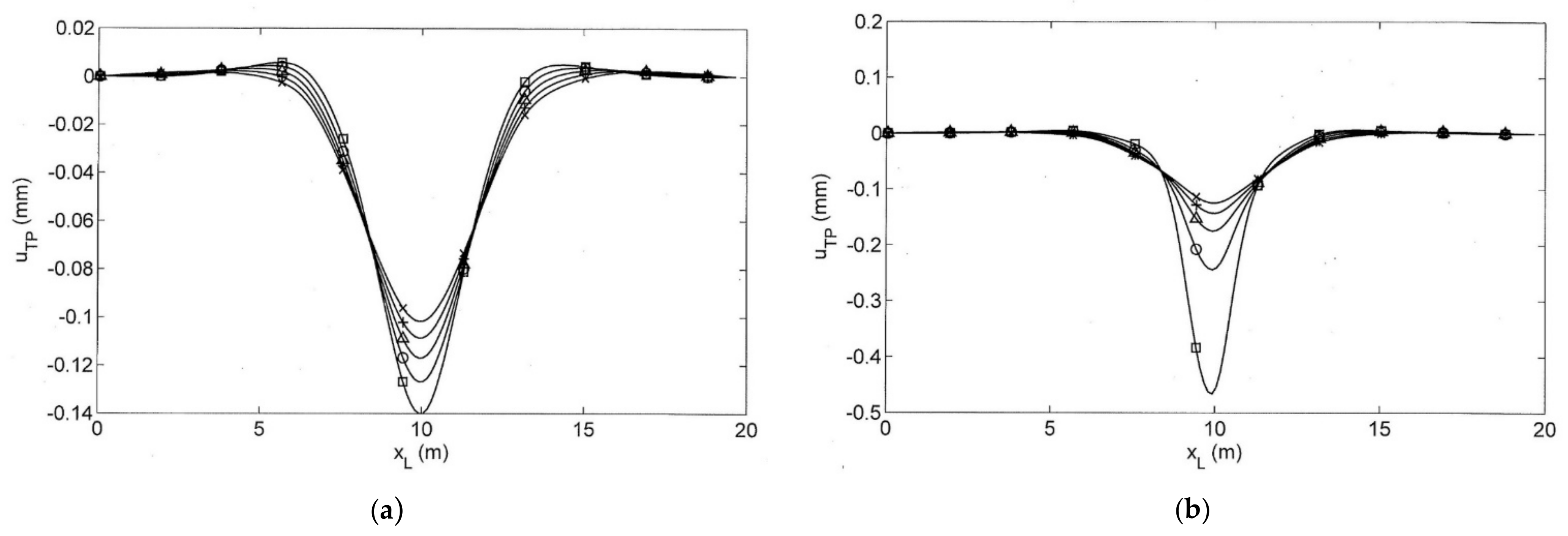
The response of the slab track depends on the stiffness of the track and the stiffness of the soil. Different track plates were investigated and the influence of the plate thickness can be found in Figure 7. If the track thickness was varied between 0.1 and 0.3 m, this means a variation in the bending stiffness by a factor 27, but the maximum displacement of the track plate just changes between 0.1 to 0.14 mm for an axle load of 100 kN. For an intact slab track, the influence of the plate stiffness is weak. In the case of track damage (1.95 m gap under the track plate, as shown in Figure 7b), the thin plate yields a much deeper displacement of 0.5 mm compared to the thicker plates. As the contact to the soil is lost, the support by the plate becomes important.
On the other hand, the soil is most important for an intact slab track. It is known (for example, [35]) that the displacement of the slab track follows the rule:
u ~ G−0.84 EI−0.16
where the shear modulus G of the soil has a five times stronger influence than the bending stiffness of the track plate. Figure 8 shows three examples close to the stiffness of the measurement example. The displacements of the rail, the track plate, and the base layer are compared where the latter are almost the same in the case of an intact slab track. The rail displacement is much deeper, between 0.48 and 0.54 mm, compared to the displacements of the track plate and base layer, which vary between 0.11 and 0.18 mm according to the rule stated in (5). The deeper rail displacements are due to the soft rail pads that are typical for slab tracks. The rail on the rail pads reacts quite locally with a narrow deflection. Within 1 to 2 m distance, the rail displacements decrease to small values which are even smaller than the base-layer displacements.
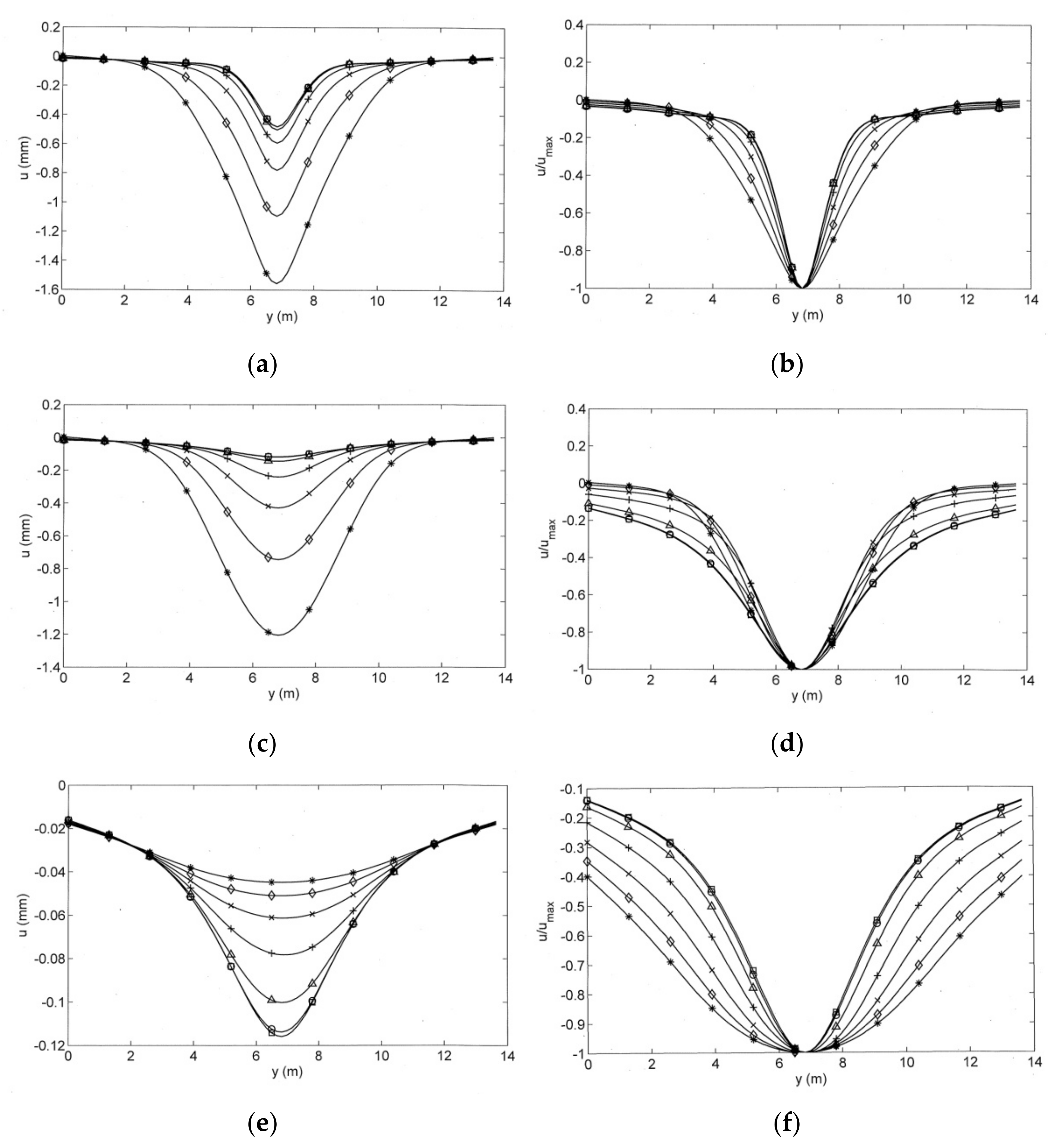
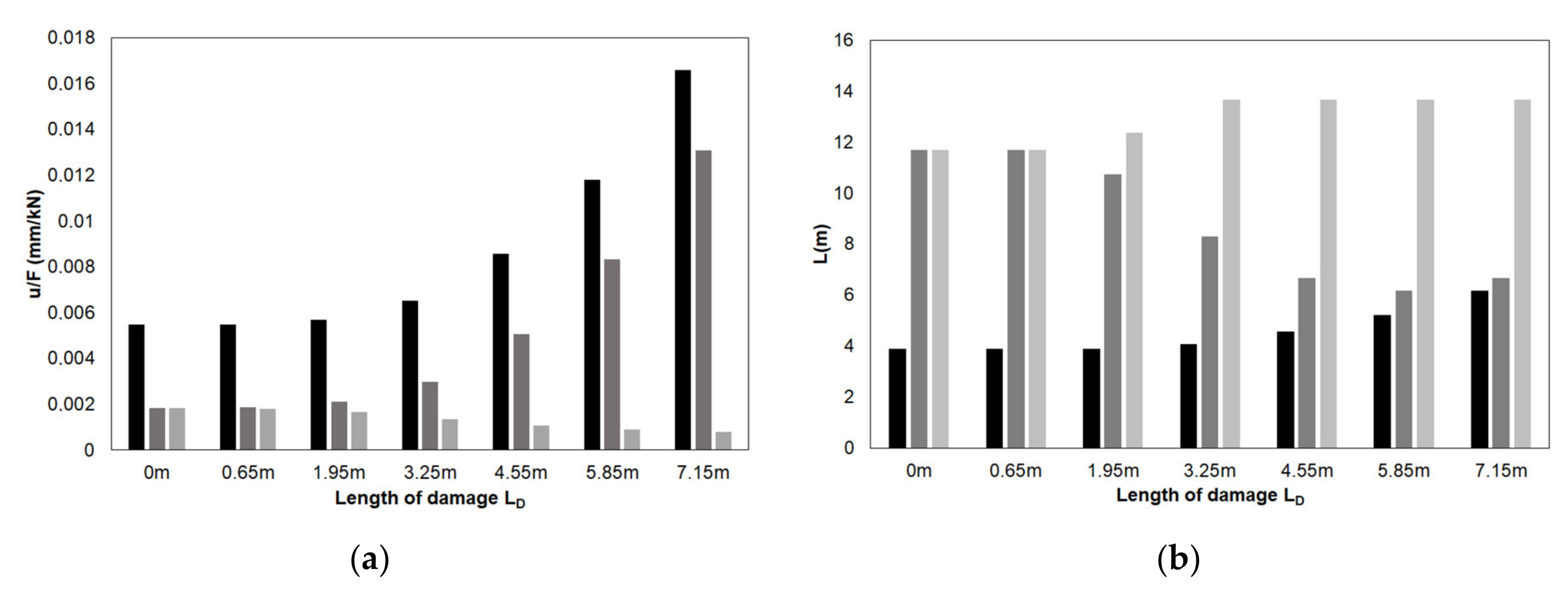
Both track models, the finite element model on Winkler soil, and the FEBEM on continuous soil, were used to identify track damage. A gap between the track plate and the base layer was varied with lengths 0.65, 1.95, 3.25, 4.55, 5.85 and 7.15 m. The resulting displacement pattern is shown in Figure 9. The displacements increase with increasing damage for the rail displacements between 0.5 and 1.6 mm. The increase is more significant for the track plate that has displacements between 0.1 and 1.2 mm. Moreover, a difference between the track plate and the base layer develops with increasing damage. The displacements of the base layer remain small or are even reduced with the track damage. In addition to the maximum displacements of the track elements, the deflection shape can also be evaluated for the influence of track damage. Figure 10 shows the absolute deflections (left) and the relative deflections (right). The absolute deflections show the increase in depth with increasing damage. This is true for the rail and plate displacements. The displacements of the base layer, however, decrease with increasing track damage. The relative displacements (Figure 10b,d,f) show the change in the deflection shape. The rail deflection becomes wider with increasing track damage whereas the plate deflection becomes narrower. This is true for the narrower damage. If the damage is wide enough, the deflection shape of the plate also widens again. The base-layer deflection becomes wider for all track damages. All values related to the displacement and the width of deflection are summarised in Figure 11a,b, where the width is quantified as the range where the displacements are deeper than 20% of the maximum. The increase in the maximum displacement of the rail and track plate and the increase in the width of the rail deflection with increasing length of damage are obvious.

7. Calculated Train Passages over Intact and Damaged Slab Tracks

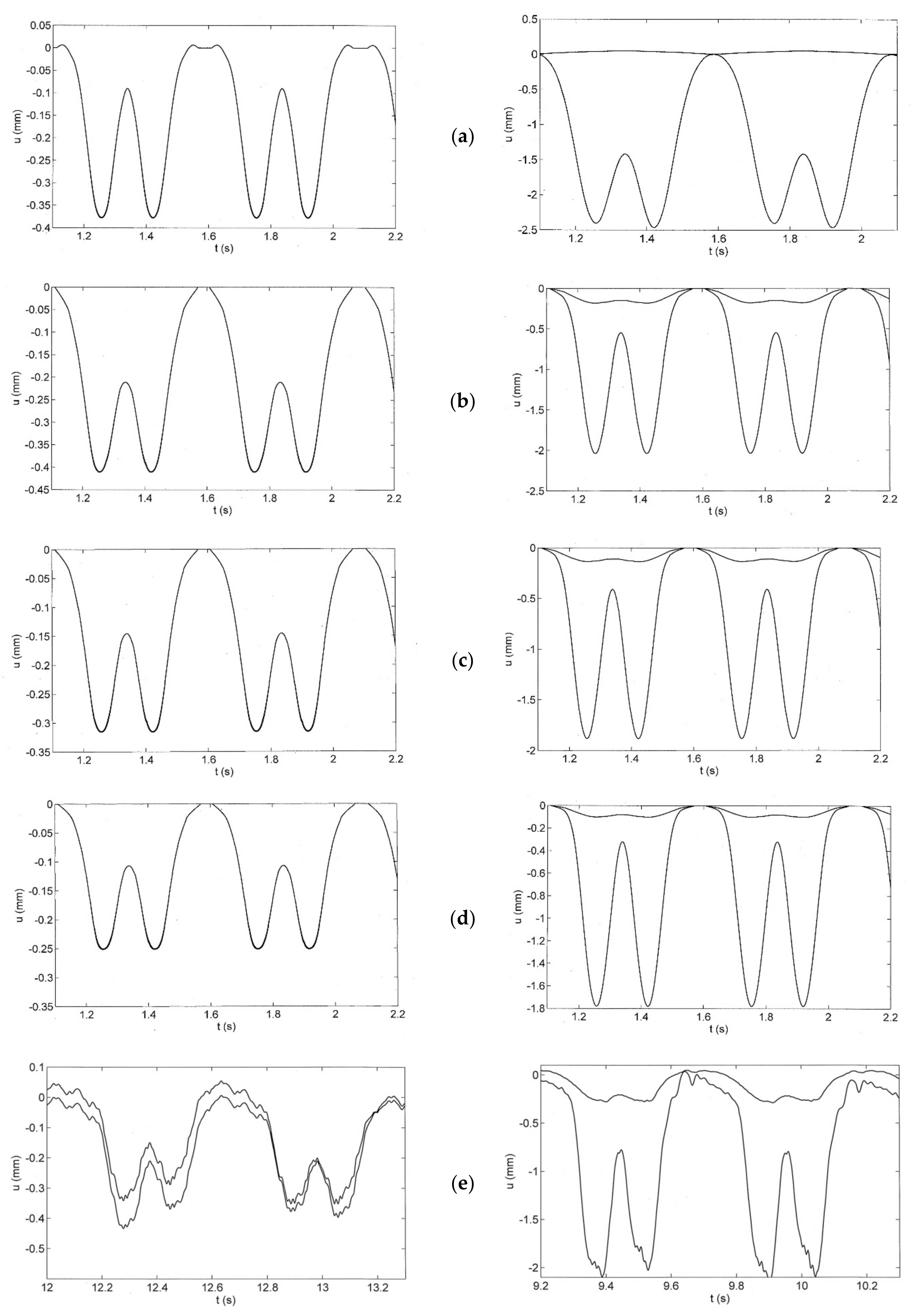
The responses of single axles are now superposed to obtain a complete train. The response to a complete train is shown in Figure 12 for some track–soil situations. Each axle load yields displacements also at the positions of the neighbouring axles so that the response under one axle is at least generated by four axle loads of two neighbouring bogies. The results are considerably deeper displacements compared to a single axle load as given in the last section. For the track on the softest soil (vS = 150 m/s), the compliance for a single axle is 2 × 10⁻⁹ N/m2, for a train it is 0.4 mm/160 kN = 2.5 × 10⁻⁹ N/m2. This “interaction” effect is strongest for the softest soil and weakest for the Winkler soil.
A stronger interaction yields a wider deformation for each axle. This width cannot be seen directly in the response to a train passage. There is, however, a clear indicator of a strong interaction. The minimum displacement between two consecutive bogies (the interbogie displacement) is deeper if the interaction is stronger. The interbogie displacement can be used as a second characteristic of the slab track response. In Figure 12a, the interbogie displacement for the FEM-on-Winkler-soil model is smallest. The track comes back to almost zero displacements between two bogies. For the FEBEM models with continuous soil, however, the track keeps about 50% of the maximum displacement between the bogies. The model that best fits the measurements in Figure 6a is the FEBEM model with a soil of vS = 175 m/s. This is also the result of the wave velocity measurement.
The different track plate damages are now analysed with the passage of two consecutive bogies (and the 175 m/s FEBEM model). The intact track shows two response curves, one curve for the rail and one curve for the track plate and the base layer, which have identical responses. With increasing track plate damage, the response of the track plate becomes stronger while the base-plate response remains small or becomes weaker with increasing damage. The big difference between track plate and base-layer response is the clear indicator of the track damage. Another indicator could be the width of the track plate deflection. From the interbogie displacement, it can be read that the track plate deflection becomes narrower for the shorter track damages, the interbogie displacements become smaller. (The trend, however, is not unique. Wider damages acquire wider track plate deflections.) Instead of the width of the track plate deflection, the width of the base-layer deflection would be a good indicator of the track damage. The base-layer deflection is very wide so that both bogies yield a single deflection in the case of strong track damage.
Finally, the width of the track plate damage was found for the gap length of 5.85 m, which yields the most realistic deflection shape and the nearest amplitudes to the measurements. The calculated results are compared with the measured results shown in Figure 13e, indicating that the chosen model displays also the most realistic deflection shape, in addition to the good agreement in the maximum amplitude.

8. Comparison of the FEM on Winkler Soil with the FEBEM with Continuous Soil

The results for the simple FEM-on-Winkler-soil model are compared with FEBEM results in Figure 9 for the axle load and in Figure 13 for the train passage. The maximum amplitudes are quite similar for the FEM and FEBEM calculations. The principal difference is found for the shape of the deflection. Whereas the FEBEM results show only negative downward displacements, the FEM results show small upward movements both for an axle load and for a train load.
More generally, the response of the FEM–Winkler model is more local and the response of the FEBEM model is more global. This is also indicated by the interbogie displacements, which are smaller for the Winkler soil.
A third discrepancy between Winkler and continuous soil is proved experimentally for ballast tracks, but it is also expected for slab tracks. For a Winkler soil, the forces and displacements are proportional. In measurements and for a continuous soil, forces and displacement are completely different. The forces are concentrated around the load (local behaviour) whereas the displacements are widely distributed (global behaviour).
These results and arguments demonstrate that the Winkler support does not appear to be an appropriate model for the soil under a railway track.

9. Further Example Applications to the Three Sites: S, W, and T

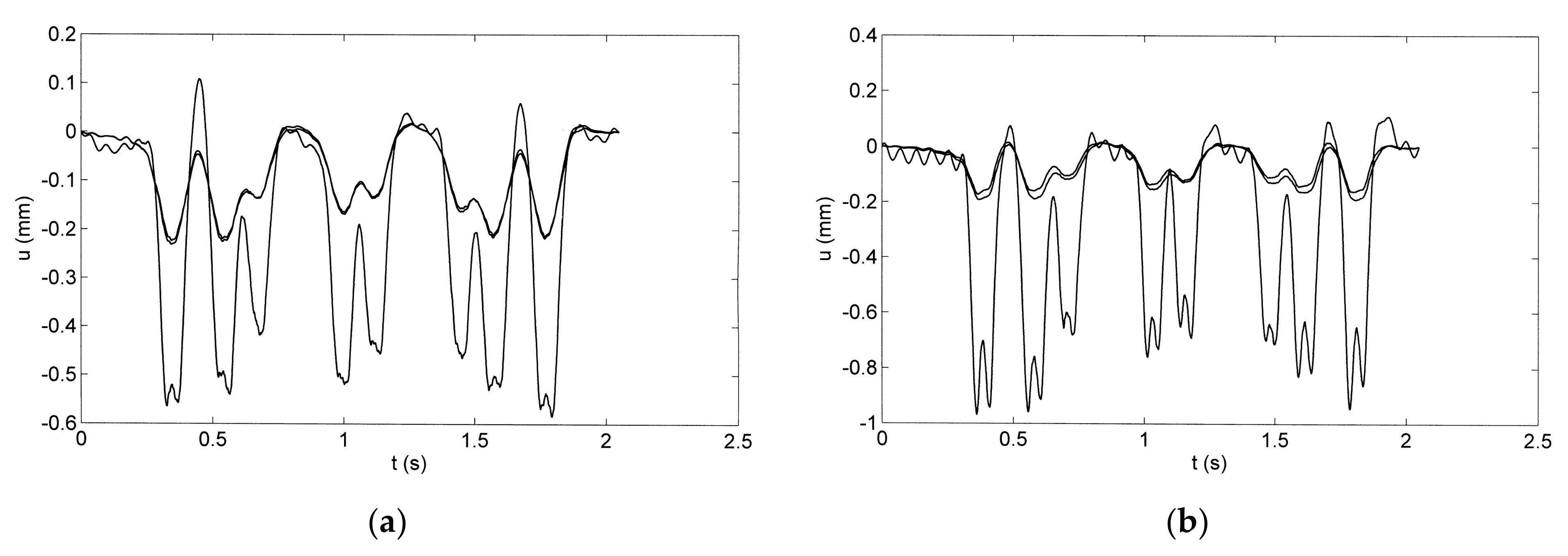
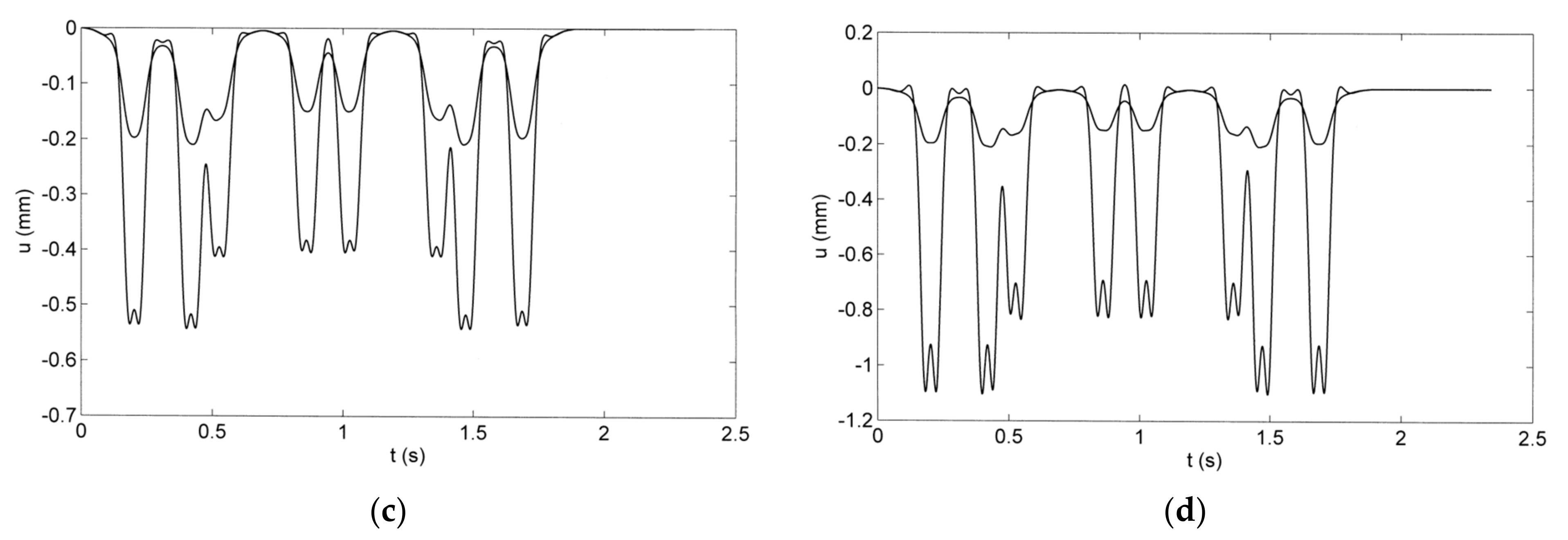
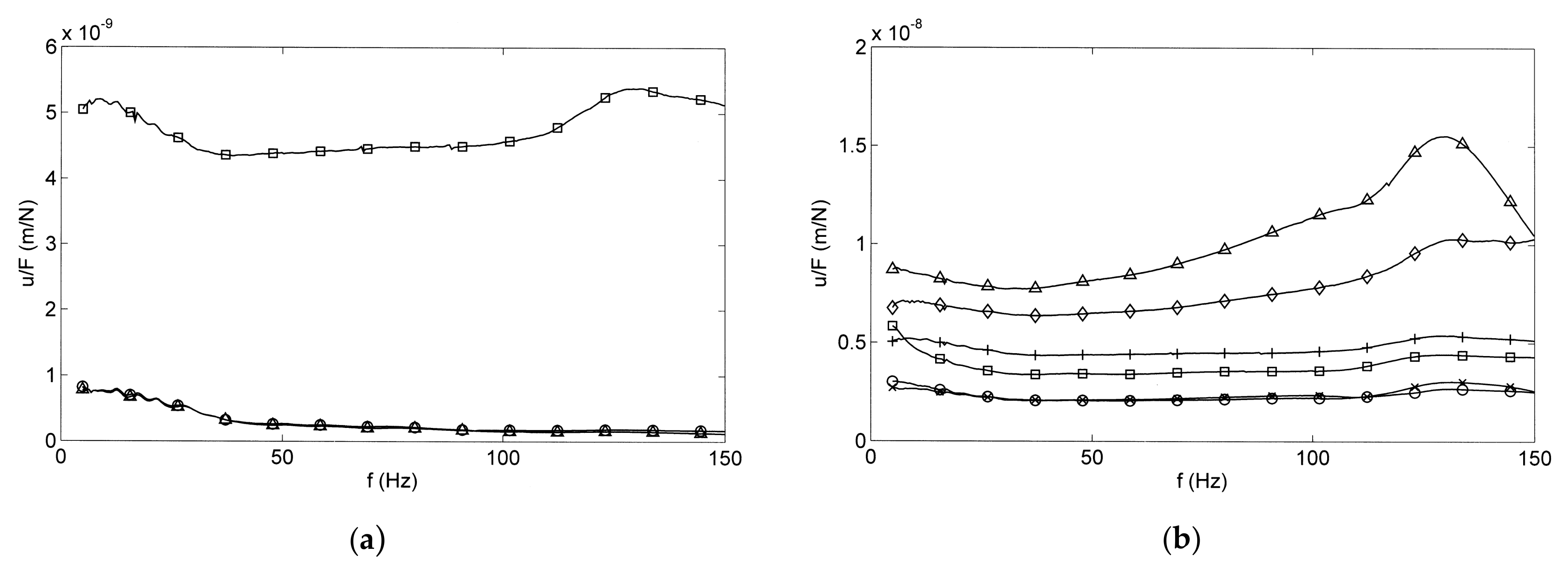
Additional results are presented for the three other slab tracks at Sites S, W, and T, which are described in Section 2. The floating-slab track with a thin rubber layer at Site S is analysed in Figure 14 for passages of ICE test trains consisting of a motor car, two passenger cars, and another motor car. All eight bogies can be clearly observed at the floating-track slab, the base plate, and the base layer for the measured (Figure 14a,b) and the calculated time histories (Figure 14c,d). The base plate and the base layer are in good contact and have almost identical results so that the expected debonding could be excluded. The displacements of the track slab are much higher than the displacements of the lower layers. Differences can be found between the displacements of the mid section and the end section of the 6 m long slab track section. The floating-track slab shows at least 50% higher amplitudes at the end section (Figure 14b,d), and, in addition, the two axles of a bogie are clearly separated. The floating-slab track at Site S is also analysed by hammer impacts where transfer functions between the displacements and the hammer force (receptance functions) are evaluated (Figure 15a for the end section). The receptances in the frequency range between 0 and 150 Hz are almost constant with some reduction below 50 Hz. The differences between the floating slab and the nonfloating layers are strong; the floating-slab amplitudes are at least five times higher. Differences are also found for different track sections on different soil conditions (Figure 15b), but no indication of track damage is found.
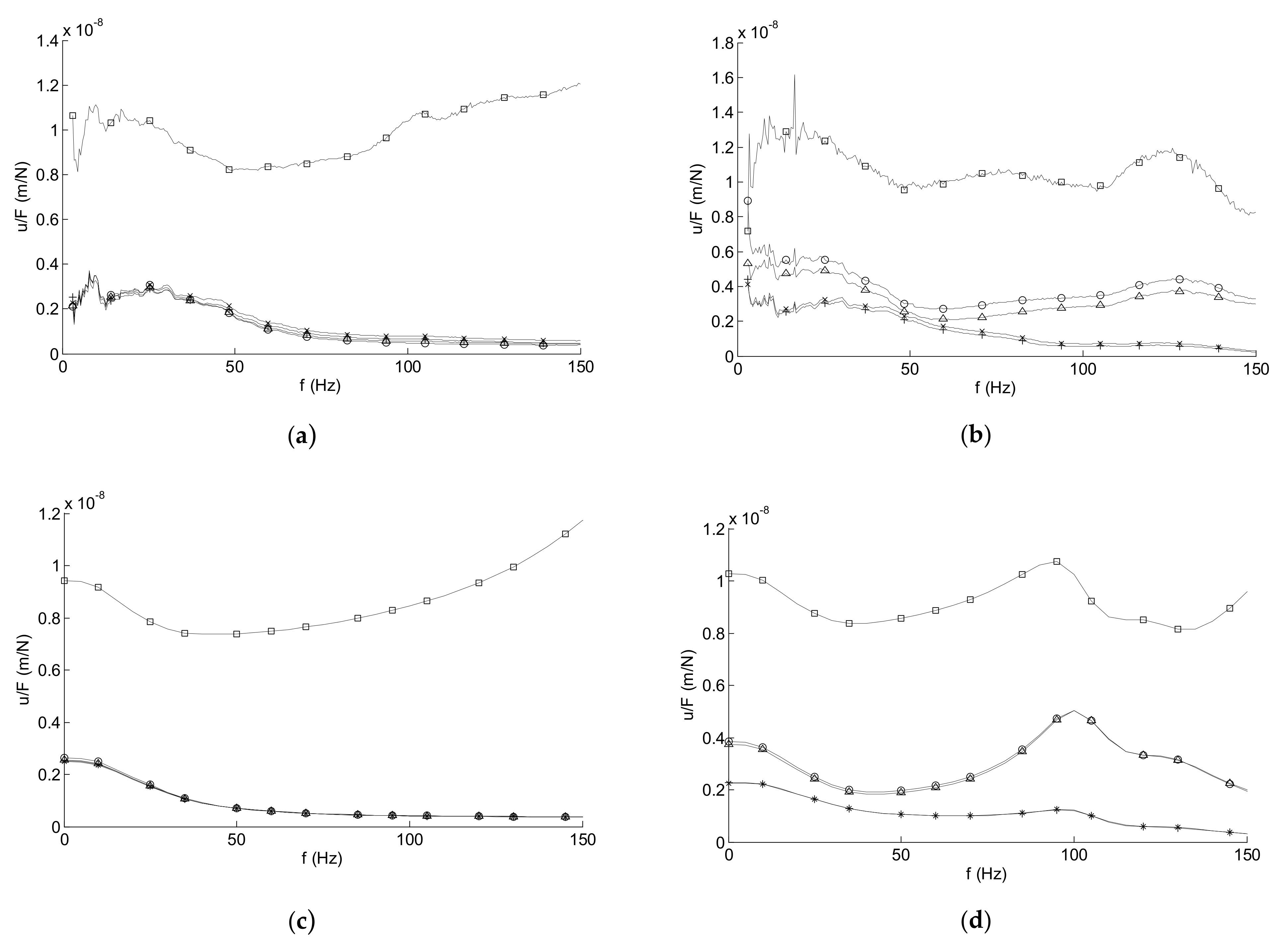
The way that receptance measurements can help in identifying slab track damage is demonstrated in Figure 16 for Site W. The measured (Figure 16a,b) and calculated receptances (Figure 16c,d) show the big difference between the rail and the four other track components, which yield almost identical results in the case of an intact track (Figure 16a,c). The track damage, a loose sleeper (without contact to the supporting track plate), results in higher amplitudes mainly for the sleeper and the track plate, and a light resonance at about 100 Hz is in good agreement with calculation and measurement (Figure 16b,d). As the damage is above the track plate, the track plate cannot compensate for the sleeper damage, which is quite contrary to the plate damage analysed in the present article. Greater difference can be found in the phase functions of the receptances, which are shown in [1] together with different hammer positions and the full details of Sites S and W.
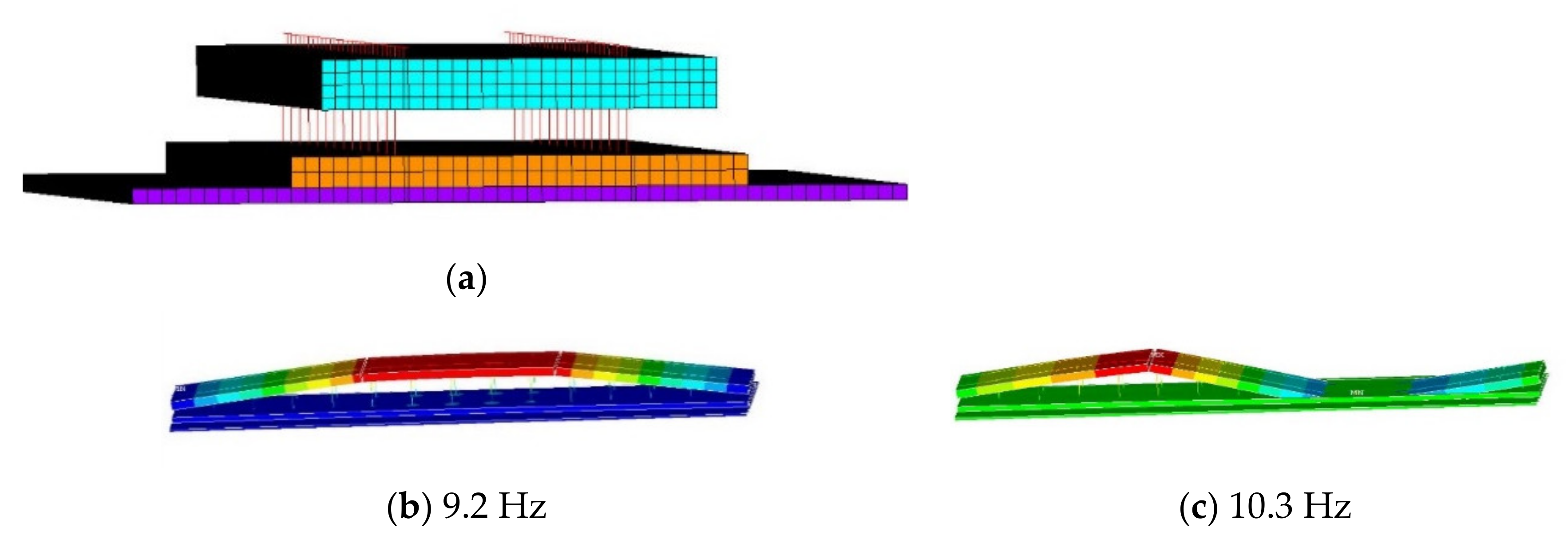
Finally, the floating-slab track with steel springs and a viscous fluid damper in the Tongji laboratory (Site S) [2] is analysed by the finite element model, as shown in Figure 17a. Three 6 m long slab segments are modelled where each slab is connected with the base plate by eight discrete spring and damper elements. The modes of the slab track with 1, 2, 3, 5, 6, and 7 maxima and frequencies between 9.2 and 41.4 Hz are shown in Figure 17b–g. The receptance function of this model in Figure 18 shows the corresponding resonances at 10, 25, and 45 Hz. The highest amplitudes are for the fundamental resonance at 10 Hz. which is in agreement with the slab mass of 1645 kg per isolator and the isolator stiffness of 6 kN/mm. The receptance is clearly decreasing for higher frequencies approximately as A ~ f−1.5, which agrees with the theory of a track beam on a flexible support and with the measured results from the wheelset drop test.
In Table 2, the stiffnesses of the different elastic layers are compared. The softest elements are the steel springs, which have only 1/50 the stiffness of the German rubber layer. Note that a normal slab track on the soil is also a kind of a “floating-slab track”. The stiffness of the soil is moderate so that theoretical resonance frequencies around 100 Hz are possible, see [35]. The resonances, however, are usually hidden because of the high radiation damping of the soil.

10. Conclusions

Two methods are presented to calculate the characteristics of slab tracks: the three-dimensional finite-element boundary-element method (FEBEM) which includes the infinite continuous soil, and the finite element method (FEM) using the Winkler soil. Results are presented for the distribution of the displacements along the track for a single axle and for the passage of a complete train. For the intact slab, the influence of the soil is dominant, whereas the track bending stiffness becomes more important for the damaged track. With correct track and soil parameters, the influence of the damage length on the displacement amplitudes and the deflection widths is analysed. The maximum plate displacement of the specific slab track increases from 0.4 mm for an intact track to 2 mm for a gap length of 7.15 m, while the width of track displacements is reduced to the half. The displacement difference between the track plate and the base layer is an additional, even better damage indicator as the base-layer displacements are reduced with increasing damage. Using these damage indicators, a slab track error, a gap between the track plate, and the base layer over a length of nine fastener spacings (5.85 m), are successfully quantified from measured train passages by comparison with the three-dimensional FEBEM calculations. A Winkler soil model is fitted to the displacement amplitude, but the width of the deflection is then considerably smaller. The realistic deformation of the track parts that are in stiff contact with the soil (the base layer in case of a damaged or a floating-slab track) can only be calculated with a continuous soil model. In general, the combination of measurements with realistic track–soil calculations can help to detect and quantify the track damage.

Author Contributions

FEM and FEBEM calculations, analysis of steel-spring floating-slab track, and editing, J.S.; FEBEM software, FEBEM calculations, and writing, L.A. All authors have read and agreed to the published version of the manuscript.

Funding

This research received no external funding.

Data Availability Statement

The data presented in this study are available on request from the corresponding author.

Acknowledgments

Thanks to S. Said who organised and performed the measurements of damaged tracks.

Conflicts of Interest

The authors declare no conflict of interest.

References

  1. Auersch, L.; Said, S. Track-soil dynamics—Calculation and measurement of damaged and repaired slab tracks. Transp. Geotech. 2017, 12, 1–14. [Google Scholar] [CrossRef]
  2. Song, J. Research on Isolator Damping in Floating Slab and Its Influence on Dynamic Response. Master’s Thesis, Tongji University, Shanghai, China, 2019. [Google Scholar]
  3. Xu, H.; Wang, P.; Xu, J. Analysis of cement emulsified asphalt mortar gap on CRTS II slab ballastless track. Appl. Mech. Mater. 2013, 405–408, 1834–1838. [Google Scholar] [CrossRef]
  4. Song, X.; Zhao, C.; Zhu, X. Temperature-induced deformation of CRTS II slab track and its effect on track dynamical properties. Sci. China Technol. Sci. 2014, 57, 1917–1924. [Google Scholar] [CrossRef]
  5. Zhu, S.; Cai, C. Interface damage and its effect on vibrations of slab track under temperature and vehicle dynamic loads. Int. J. Non-Linear Mech. 2014, 58, 222–232. [Google Scholar] [CrossRef]
  6. Wang, J.; Zhou, Y.; Wu, T.; Wu, X. Performance of cement asphalt mortar in ballastless slab track over high-speed railway under extreme climate conditions. Int. J. Geomech. 2019, 19, 04019037. [Google Scholar] [CrossRef]
  7. Zhu, S.; Wang, M.; Zhai, W.; Cai, C.; Zhao, C.; Zeng, D.; Zhang, J. Mechanical property and damage evolution of concrete interface of ballastless track in high-speed railway: Experiment and simulation. Constr. Build. Mater. 2018, 187, 460–473. [Google Scholar] [CrossRef]
  8. Zhang, Y.; Wu, K.; Gao, L.; Yan, S.; Cai, X. Study on the interlayer debonding and its effects on the mechanical properties of CRTS II slab track based on viscoelastic theory. Constr. Build. Mater. 2019, 224, 387–407. [Google Scholar] [CrossRef]
  9. Ren, J.; Ji, W.; Xiao, L.; Wei, K.; Haolan, L.; Shijie, D. Influence of cement asphalt mortar debonding on the damage distribution and mechanical responses of CRTS I prefabricated slab. Constr. Build. Mater. 2020, 230, 116995. [Google Scholar] [CrossRef]
  10. Zhong, Y.; Gao, L.; Cai, X.; An, B.; Zhang, Z.; Lin, J.; Qin, Y. An improved cohesive zone model for interface mixed-mode fractures of railway slab tracks. Appl. Sci. 2021, 11, 456. [Google Scholar] [CrossRef]
  11. Wang, P.; Xu, H.; Chen, R. Effect of cement asphalt mortar debonding on dynamic properties of CRTS II slab ballastless track. Adv. Mater. Sci. Eng. 2014, 2014, 193128. [Google Scholar] [CrossRef]
  12. Zhu, S.; Fu, Q.; Cai, C.; Spanos, D. Damage evolution and dynamic response of cement asphalt mortar layer of slab track under vehicle dynamic load. Sci. China Technol. Sci. 2014, 57, 1883–1894. [Google Scholar] [CrossRef]
  13. Ren, J.; Yang, R.; Wang, P.; Dai, F.; Yan, X. Influence of contact loss underneath concrete underlayer on dynamic performance of prefabricated concrete slab track. Rail Rapid Transp. 2017, 231, 1. [Google Scholar]
  14. Han, J.; Zhao, G.; Xiao, X.; Wen, Z.; Guan, Q.; Jin, X. Effect of softening of cement asphalt mortar on vehicle operation safety and track dynamics. J. Zhejiang Univ.-Sci. A Appl. Phys. Eng. 2015, 16, 976–986. [Google Scholar] [CrossRef] [Green Version]
  15. Xu, J.; Wang, P.; Liu, H.; Hu, Z.; Chen, R. Identification of internal damage in ballastless tracks based on Gaussian curvature mode shapes. J. Vibroeng. 2016, 18, 5217–5229. [Google Scholar] [CrossRef] [Green Version]
  16. Ulriksen, M.; Bernal, D.; Damkilde, L. Shaped input distributions for structural damage localization. Mech. Syst. Signal Processing 2018, 110, 499–508. [Google Scholar] [CrossRef]
  17. Yan, A.; Golinval, J. Null subspace-based damage detection of structures using vibration measurements. Mech. Syst. Signal Process. 2006, 20, 611–626. [Google Scholar] [CrossRef] [Green Version]
  18. Döhler, M.; Mevel, L.; Hille, F. Subspace-based damage detection under changes in the ambient excitation statistics. Mech. Syst. Signal Process. 2014, 45, 207–224. [Google Scholar] [CrossRef]
  19. Ha, N.; Golinval, J. Localization and quantification of damage in beam-like structures using sensitivities of principal component analysis results. Mech. Syst. Signal Process. 2010, 24, 1831–1843. [Google Scholar]
  20. Zimmermann, H. Die Berechnung des Eisenbahnoberbaus; Ernst & Korn: Berlin, Germany, 1888. [Google Scholar]
  21. Winkler, E. Die Lehre von der Elastizität und Festigkeit; Dominicus: Prague, Czech Republic, 1867. [Google Scholar]
  22. Zhai, W. The Vertical Coupling Dynamics of Vehicle and Track as an Integral System. Ph.D. Thesis, Southwest Jiaotong University, Chengdu, China, 1991. [Google Scholar]
  23. Knothe, K.; Grassie, S. Modelling of railway track and vehicle/track interaction at high frequencies. Veh. Syst. Dyn. 1993, 22, 209–262. [Google Scholar] [CrossRef]
  24. Takemiya, H.; Bian, X. Substructure simulation of inhomogeneous track and layered ground dynamic interaction under train passage. J. Eng. Mech. ASCE 2005, 131, 699–711. [Google Scholar] [CrossRef]
  25. Jones, C. Use of numerical models to determine the effectiveness of anti-vibration system for railways. Proc. Inst. Civ. Eng. Transp. 1994, 105, 43–51. [Google Scholar] [CrossRef]
  26. Sheng, X.; Jones, C.; Petyt, M. Ground vibration generated by a load moving along a railway track. J. Sound Vib. 1999, 225, 129–156. [Google Scholar] [CrossRef]
  27. Lombaert, G.; Degrande, G. Ground-borne vibration due to static and dynamic axle loads of InterCity and high-speed trains. J. Sound Vib. 2009, 319, 1036–1066. [Google Scholar] [CrossRef]
  28. Auersch, L. Static and dynamic behaviours of isolated and un-isolated ballast tracks using a fast wavenumber domain method. Arch. Appl. Mech. 2017, 87, 555–574. [Google Scholar] [CrossRef]
  29. Ju, S.; Lin, H. Experimentally investigating finite element accuracy for ground vibrations induced by high-speed trains. Eng. Struct. 2008, 30, 733–746. [Google Scholar] [CrossRef]
  30. Auersch, L. Dynamics of the railway track and the underlying soil: The boundary-element solution, theoretical results and their experimental verification. Veh. Syst. Dyn. 2005, 43, 671–695. [Google Scholar] [CrossRef]
  31. Galvin, P.; Romero, A.; Dominguez, J. Fully three-dimensional analysis of high-speed train-track-soil-structure dynamic interaction. J. Sound Vib. 2010, 329, 5147–5163. [Google Scholar] [CrossRef]
  32. Lombaert, G.; Degrande, G.; Vanhauwere, B.; Vandeborght, B.; François, S. The control of ground-borne vibrations from railway traffic by means of continuous floating slabs. J. Sound Vib. 2006, 297, 946–961. [Google Scholar] [CrossRef]
  33. Steenbergen, M.; Metrikine, A.; Esveld, C. Assessment of design parameters of a slab track railway system from a dynamic viewpoint. J. Sound Vib. 2007, 306, 361–371. [Google Scholar] [CrossRef]
  34. Galvin, P.; Romero, A.; Dominguez, J. Vibrations induced by HST passage on ballast and non-ballast tracks. Soil Dyn. Earthq. Eng. 2010, 30, 862–873. [Google Scholar] [CrossRef] [Green Version]
  35. Auersch, L. The dynamic behaviour of slab tracks on homogeneous and layered soils and the reduction of ground vibration by floating slab tracks. J. Eng. Mech. 2012, 138, 923–933. [Google Scholar]
  36. Shih, J.; (University of Birmingham, Birmingham, UK), Approximate Soil Layers. Private communication, 2019.
  37. Milne, D.; Pen, L.; Thompson, D.; Powrie, W. Automated processing of railway track deflection signals obtained from velocity and accelerometer mesurements. Rail Rapid Transp. 2018, 232, 2097–2110. [Google Scholar] [CrossRef] [PubMed]
Figure 1. Experimental methods for identifying track properties and damage: (a) train passage at Site G; (b) hammer impacts at Site W; (c,d) wheelset drop tests at Site T.
Civileng 03 00055 g001
Figure 2. Elements of slab track systems and their presence at the different sites; ↓ indicates measuring points.
Civileng 03 00055 g002
Figure 3. Finite element slab-track models with (from top to bottom) rails and rail pads (red), track plate (turquoise), mortar/gap layer (orange), base layer (violet), and Winkler support (green).
Civileng 03 00055 g003
Figure 4. The train configuration with car length, bogie distance, and axle distance.
Civileng 03 00055 g004
Figure 5. Wave velocity measurements of the soil at Site W; response to hammer impact at 1 to 60 m, vS = 175 m/s.
Civileng 03 00055 g005
Figure 6. Measured passages of a long German ICE train with vT = 160–180 km/h over a floating-slab track with 6 m long segments at Site S: (a) middle of the track plate and (b) end of the track plate.
Civileng 03 00055 g006
Figure 7. Calculated distributions of the track-plate displacements for different thicknesses of the plate tP = 0.1, 0.15, 0.2, 0.25, and 0.3 m: (a) intact slab track and (b) track plate damage (gap to base layer) of length LD = 1.95 m (FEM models).
Civileng 03 00055 g007
Figure 8. Calculated distributions of the slab track displacements for different soils of vS = (a) 150, (b) 175, and (c) 200 m/s; ☐ rail, ◯ track plate ≈ △ base layer, (FEBEM models).
Civileng 03 00055 g008
Figure 9. Calculated distributions of the slab track displacements for different lengths of track plate damage (gap to base layer): LD = (a) 0 (intact), (b) 0.65, (c) 1.95, (d) 3.25, (e) 4.55, (f) 5.85, and (g) 7.15 m; ☐ rail, ◯ track plate, △ base layer, FEM results (left), FEBEM results (right).
Civileng 03 00055 g009aCivileng 03 00055 g009b
Figure 10. Calculated displacement distributions of the (a,b) rail, (c,d) track plate, and (e,f) base layer due to an axle load of FT = 100 kN. Slab track on a soil of vS = 200 m/s with increasing damage length: LD = ☐ 0, ◯ 0.65, △ 1.95, + 3.25, ✕ 4.55, ◇ 5.85, and ∗ 7.15 m between track plate and base layer; (a,c,e) absolute displacements and (b,d,f) relative displacements (FEBEM results).
Civileng 03 00055 g010
Figure 11. Calculated displacements of the rail (black), track plate/sleeper (mid grey), and base layer (light grey) for a slab track on a soil of vS = 200 m/s under an axle load of FT = 100 kN (FEBEM): (a) maximum displacements and (b) widths of displacements for track plate damages of different lengths LD.
Civileng 03 00055 g011
Figure 12. Calculated track plate displacements under train passages: (a) FEM model; FEBEM models with vS = (b) 150, (c) 175, and (d) 200 m/s, intact slab track (left) and damaged slab track (gap of LD = 5.85 m).
Civileng 03 00055 g012aCivileng 03 00055 g012b
Figure 13. Calculated displacement for the track plate and base layer under the passage of four bogies: (a) FEM model; FEBEM models with vS = (b) 150, (c) 175, (d) 200 m/s, and (e) measurements, intact slab track (left, track plate and base layer have identical displacements) and damaged slab track (gap of LD = 5.85 m).
Civileng 03 00055 g013
Figure 14. Track-slab, base-plate, and base-layer displacements of the floating-slab track at Site S under the passage of a short 4-unit ICE test train, measurement (a,b) and calculation ((c,d) FEBEM results), (a,c) at the middle and (b,d) at the end of the 6 m long track segment.
Civileng 03 00055 g014aCivileng 03 00055 g014b
Figure 15. Receptance functions of slab tracks at Site S: (a) measuring points at ☐ track plate and ◯ base plate ≈ △ base layer; (b) floating slab of different track sections on two different soils, ◯, ✕ mid section, ☐, △, +, and ◇ end section.
Civileng 03 00055 g015
Figure 16. Receptance functions of slab tracks at Site W: measurement (a,b) and calculation ((c,d) FEBEM results), ☐ rail, ◯ sleeper, △ track plate ✕ base plate, + base layer, intact (left), and damaged track (right).
Civileng 03 00055 g016
Figure 17. Finite element model (a) and the first modes (b–g) of the floating-slab track on steel spring viscous dampers with three 6 m long segments.
Civileng 03 00055 g017aCivileng 03 00055 g017b
Figure 18. Transfer functions (receptances) of the floating-slab track with steel springs and viscous dampers: measurement (red) calculation (blue, FEM results).
Civileng 03 00055 g018
Table 1. Parameter variation in the slab track (Site G, standard parameters are underlined).
PartsParametersValues
Railsbending stiffness of the rails (UIC60)EI = 12.6 × 10⁶ Nm2
mass per length of the railsm’R = 2 × 60 kg/m
Slab trackdistance of the rail supports d = 0.65 m
stiffness of the rail padskR = 60 × 106 N/m
hysteretic damping of the rail padsDR = 10%
modulus of elasticity of concreteE = 3.6 × 10¹⁰ N/m2
mass density of concreteρ = 2.5 103 kg/m3
width of the track plateaP = 2.8 m
height of the track platehP = 0.1, 0.15, 0.2, 0.25, 0.3 m
modulus of elasticity of the mortarEM = 5 × 10⁹ N/m2
modulus of elasticity of the base layerEL = 5 × 10⁹ N/m2
width of the base layer aL = 3.5 m
height of the base layerhL = 0.3 m
Soilshear modulus of the soilG = 4.5, 6.125; 8 × 10⁷ N/m2
shear wave velocity of the soilvS = 150, 175, 200 m/s
mass density of the soilρB = 2 × 10³ kg/m3
Poisson’s ratio of the soilνB = 0.33
hysteretic damping of the soilDB = 2.5%
Table 2. Parameters of the track–soil systems at Sites W, S, and T.
ComponentsSite WSite SSite T
Track plateh1 = 0.15 mh1 = 0.15 mh1 = 0.325 m
Base plateh2 = 0.17 mh2 = 0.15 mh2 = 0.2 m
Base layerh3 = 0.3 mh3 = 0.3 mh3 = 0.1 m
Elastic layerSoilRubberSteel springs
Stiffness k--k = 6 × 10⁶ N/m
Damping c--c = 6 × 10³ Ns/m
Stiffness per track length-k’ = 4.5 × 10⁸ N/m2k’ = 8 × 10⁶ N/m2
Stiffness per track area-k’’ = 1.5 × 10⁸ N/m3k’’ = 3 × 10⁶ N/m3
Shear modulus of the soilG = 6 × 10⁷ N/m2G = 13 × 107 N/m2-
Mass of floating slab per track length-m’R = 1050 kg/mm’R = 2200 kg/m
Publisher’s Note: MDPI stays neutral with regard to jurisdictional claims in published maps and institutional affiliations.