1. Introduction
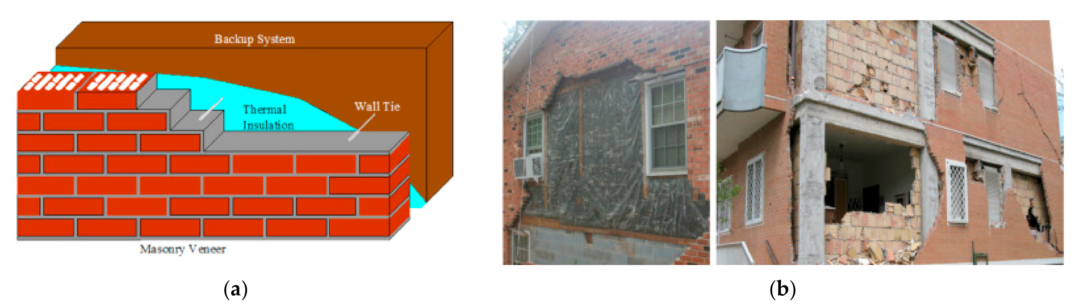
Brick masonry veneer walls consist of an exterior cladding acting as a skin of the structure and separated from it by an air cavity, which is often filled with insulation material (
Figure 1a). Due to their aesthetics, durability and good thermal behavior, veneer walls are commonly observed in several countries in the world as cladding on buildings. In Portugal, the backing structural system typically consists of reinforced concrete masonry infilled frames. This constructive solution can be also applied for the renovation of traditional façades to improve the energy efficiency of existing buildings.
Brick masonry veneer walls are attached to the backing system through distinct types of ties, generally made of steel and with a highly varying geometry. The main role of wall ties on masonry veneer walls is transferring the out-of-plane lateral loads to the structure providing a connection between both. That is why ties should have adequate resistance and stiffness in tension and compression, as well as shear flexibility to accommodate in-plane movements. A comprehensive overview of brick masonry veneer walls and their structural behavior can be found in [
1].
Nevertheless, some recent earthquakes brought to light some fragilities of this constructive system, resulting in damages due to combined in-plane and out-of-plane loads [
2,
3]. Past studies state that buildings with unreinforced masonry walls were responsible for 60% of the fatalities caused by earthquakes in the second half of the 20th century [
4,
5]. Post-earthquake observations showed that brick veneer walls have exhibited extensive diagonal cracking and, particularly, out-of-plane detachment from the backing support [
6].
Figure 1b shows examples of failure of veneer masonry walls after recent earthquakes due to inadequate connection with the backing system. One justification for the observed seismic vulnerability can be the absence of specific regulations for the design of brick masonry veneers and the ties. Brick masonry veneer walls are considered as enclosures and not as structural elements, despite earthquakes and wind loading subject them to actions that force them to behave structurally.
Moreover, due to their mass and connection to the backing structural system, veneer walls influence the overall dynamic response of the building under seismic actions [
7,
8]. Thus, it is very important to analyze the behavior of these structures under lateral actions to better predict their seismic performance and to develop suitable design approaches. Unfortunately, enough information is not available on common constructive practices and considerable research is still being conducted toward that objective. The literature has pointed out that the seismic behavior of brick veneers depends on several features, such as the tie connection spacing and stiffness, the relative stiffness between the facing and backing structure, the support conditions of brick veneer and the backup, the location of wall edges and openings, the air cavity width, and the type of loading applied to the wall [
9]. Several works have been developed to characterize the veneer walls with light wood or steel frames [
10,
11,
12,
13]. However, a gap in the literature was found with reference to the seismic performance of masonry veneer walls, in which the backing system is composed of reinforced concrete (RC) frames filled with unreinforced masonry walls [
1].
The present research focuses on this research gap dealing with the cyclic behavior of steel ties used to attach the brick masonry veneers to brick masonry infill walls. The research relies on experimental and numerical analysis to mainly evaluate the seismic behavior of tie connections. The main objective is to develop guidelines for seismic design and detailing of brick masonry veneer walls and tie connections. In this work, a numerical modelling approach is presented, intended to simulate the experimental results of tension and compression tests performed on masonry prisms connected by means of steel ties.
The paper first briefly introduces the masonry veneer wall system and then presents the experimental campaign carried out. The extensive experimental campaign included both the characterization of the materials individually (i.e., brick units, mortar and ties) and the whole system (brick masonry prisms connected with ties). Then, a description of the numerical approach proposed to simulate the tension–compression behavior of tie connections in brick masonry walls is presented. The numerical approach was finally validated by comparing the results obtained from the numerical analysis with the results from the experimental campaign.
2. Ties on Brick Veneers Anchored to Brick Masonry Infills
Masonry veneer walls have become a widespread construction system in the last 50 years, and it consists essentially of an outer envelope wall that works as a skin of the building and is separated from the structural system by an air cavity. They are considered as non-structural elements and are anchored to the backing system (e.g., light wood, steel frames or masonry infill walls) through anchors (e.g., steel ties) and supported vertically by the foundation or other structural elements. The main role of ties on masonry veneers is to transfer out-of-plane load directly to the backing and thus should have adequate resistance and stiffness in tension and compression, as well as shear flexibility to accommodate in-plane movements [
14].
Thus, the lateral stability of brick masonry veneer walls under seismic loading is ensured by its connection to the backup system through a variety of ties. The inadequate design of the ties or the lack of sufficient ties is a common construction deficiency of the system. Tie connection failures are often the result of tie pull-out from poor mortar joints and/or too short tie embedment length into the mortar joint [
1]. Other common deficiencies that increase the seismic vulnerability of the system are the excessive deformation of the ties due to the misalignment of the mortar joints or a possible tie fracture caused by the corrosion of the steel.
Several authors have carried out experimental campaigns on the shear, tension and compression behavior of tie connections [
10,
11,
15,
16,
17,
18,
19]. Nevertheless, as previously mentioned, most of these campaigns have focused on the mechanical behavior of steel ties connecting brick veneer walls to timber frame buildings. Therefore, additional research is needed to characterize the behavior of the common steel ties that are used when brick masonry infill walls are used as the backing system, which is more common in Portugal and other Mediterranean countries. The geometry of steel ties is noted to vary considerably from the ones used in timber frame construction [
14]. Moreover, there are certain parameters, such as the level of embedment of the tie within the masonry, that are specific of this construction system and have a definite influence on the mechanical behavior of the tie under seismic action.
As a summary of the findings observed in the literature that can be applicable to the construction system under study, previous experimental works have shown that the cyclic behavior of the tie was nonlinear since early stage and had reasonable energy dissipation capacity [
17]. The parameters that are reported to be most influential in the seismic behavior and capacity are the tie shape and bend eccentricity [
17], and the tie thickness and embedment length [
15]. Results from Mertens et al. [
18] on brick-tie assemblies revealed that the buckling of the tie was a key factor on the capacity of the tie, whereas results from Ribeiro et al. [
19] also on brick masonry assemblies concluded that the grout injection strongly influences the performance of the system.
3. Experimental Setup and Main Results
The experimental characterization of brick masonry veneers has necessarily considered the system composed of the brick masonry veneer, the backup wall and the ties connecting the masonry veneer and the backup wall. Some experimental investigations had focused on the static in-plane and out-of-plane behavior of the brick masonry veneer systems [
10,
12,
13,
19,
20]. Some of the works have also focused on the dynamic shaking table tests of both brick veneer elements [
7,
10,
12,
13,
16,
21,
22,
23,
24] or full-scale or reduced-scale buildings with attached brick veneer walls [
10,
12,
19,
21,
25,
26,
27,
28,
29].
Based on experimental research available in the literature, it is concluded that the composite systems with flexible backing structures (e.g., wood stud walls) with brick veneers attached have been reasonably treated by the research community. However, much better insight is needed to analyze the seismic behavior of composite systems with different backing structures. Based on the available experimental studies, the out-of-plane response of brick veneer walls seems to be governed by the backing wall stiffness and the properties of the veneer anchors, including typology, stiffness and grid spacing. Nevertheless, it is considered that there is a research gap on the seismic performance of brick veneers attached to reinforced concrete moment resisting framed structures, namely at the level of the interaction between the veneer and the resisting system and at the level of the local behavior of tie connections. Note that, despite very different types of commercial ties can be used both for infill and for masonry veneer walls, no experimental research exists on the characterization of their seismic performance.
The present paper specifically focuses on the experimental characterization of tie connections. An experimental campaign of different brick-tie-brick assemblages subjected to cyclic tension–compression and shear loading was carried out and is discussed in the present section. Nevertheless, before the cyclic tests were performed, a detailed characterization of the materials composing it (i.e., brick, mortar and ties) was also carried out and is briefly described in the following sections.
3.1. Experimental Characterization of Materials
The veneer wall system combines different types of bricks and mortar (veneer and infill wall) and wall ties. Therefore, it is needed to obtain the mechanical behavior and mechanical properties of these materials. An important and extensive experimental campaign was developed to characterize the mechanical and physical behavior of constituents of masonry veneer walls. It is noted that the research mainly focused on the materials composing the brick veneer walls and wall ties given that much information on the characterization of brick masonry infill already exist [
30,
31,
32,
33].
3.1.1. Brick Units
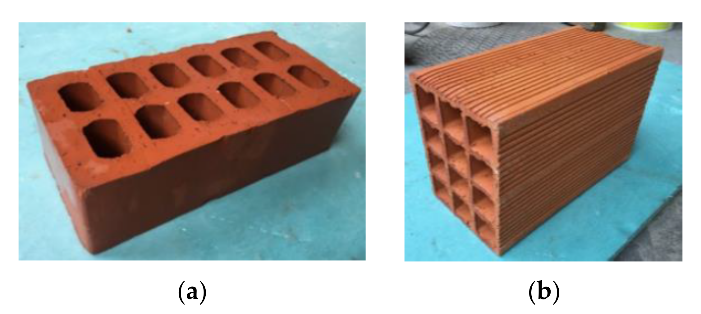
The brick masonry veneer prisms are built with ceramic bricks with vertical holes with approximately 237 mm × 115 mm × 70 mm (length × thickness × height). The masonry infill prisms are built with brick units with horizontal perforation and with approximately 300 mm × 150 mm × 200 mm (length × thickness × height).
Figure 2 shows the brick units used for the veneer (left) and the infill prisms (right). Both units were selected because they are produced in Portugal and are widely used in current construction practice.
The compressive strength of the brick units was obtained through NP EN 772-1 [
35]. Results are presented in detail in Martins [
34]. Three directions were considered given the anisotropic nature of the perforated brick units, namely the parallel direction to perforations and the two perpendicular directions to perforations. In summary, despite the high coefficient of variation observed (around 20%), the normalized compressive strength in the stronger direction (parallel to the perforations) is 24 MPa and 4 MPa for the veneer and infill brick unit, respectively.
3.1.2. Mortar
Two types of mortar were considered for masonry veneer and infill prisms. The veneer units were assembled with pre-mixed water-repellent cement mortar recommended by the veneer bricks manufacturer. For the infill prism, a pre-mixed M10 mortar was used to bond the units. The thickness adopted for the brick prims was 15 mm to make the best possible levelling of the tie.
The water content of mixes was defined in advance, based on the recommendations of the mortar manufacturers and workability tests. For this, the mortar was studied in the laboratory to find the appropriate water content so that adequate workability could be obtained, following the EN 1015-3 standard [
36]. The reader is referred to Martins [
34] for more details. In summary, the average values of compressive strength obtained from the compression tests were 5.2 MPa and 6.9 MPa for the mortar applied for the veneer and infill prisms, respectively.
3.1.3. Ties
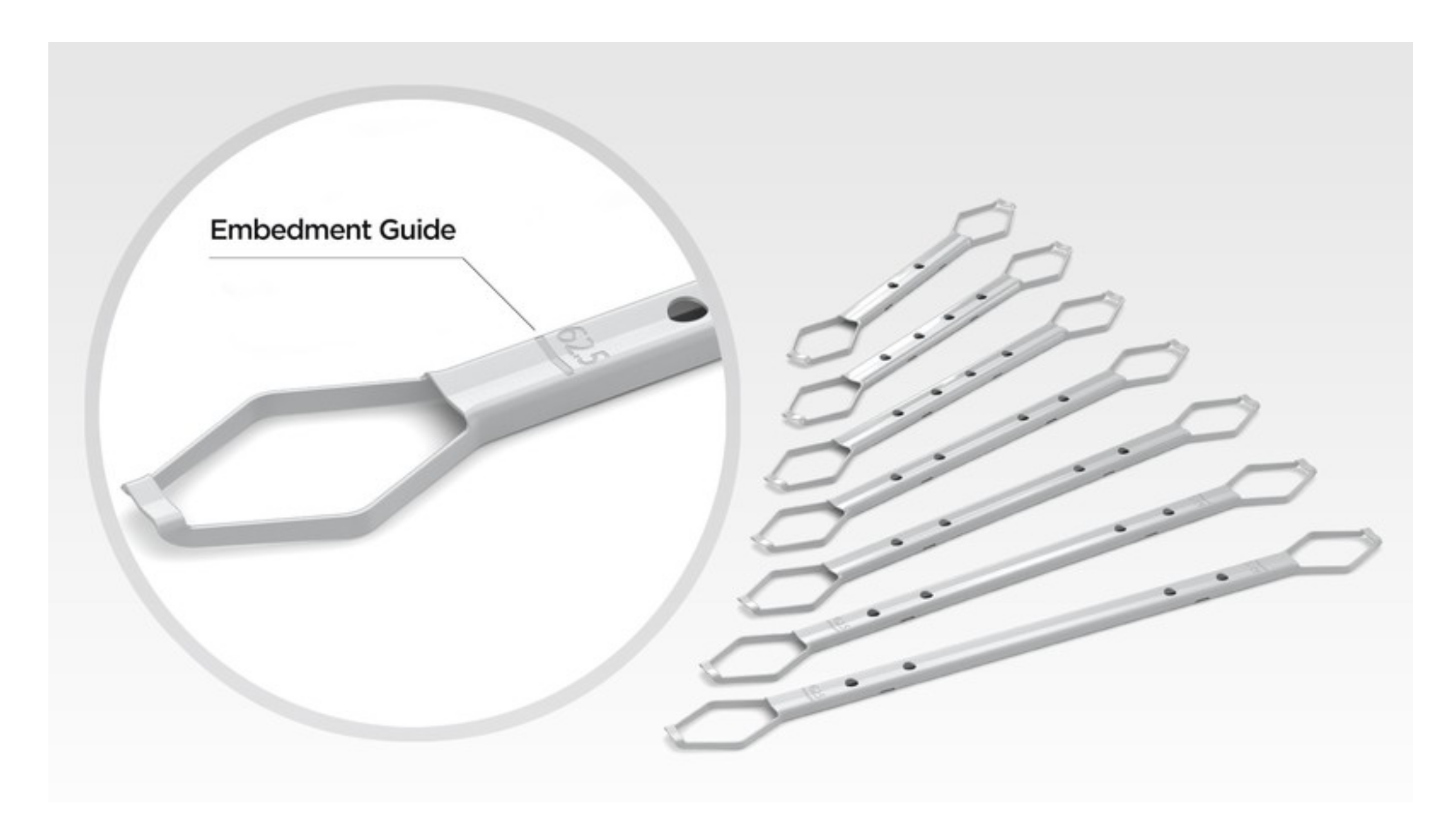
Several wall ties were considered during the broader experimental campaign shown in Martins [
34]. However, in the present paper, only the results for one type of tie were considered, namely the tie that showed a good and similar behavior in tension and compression. The tie is a stainless-steel commercial tie from
Ancon building products. It has a U-shaped cross-section in the central part and the two extremes have a clamp shape with decreased cross-section (
Figure 3). Regarding the general dimensions of the tie used in the assemblages, the length is 225 mm, the thickness is 23 mm in the central part. The overall section area is 23 mm
2. It is noted that the tie was not characterized in the laboratory.
3.2. Experimental Characterization of Tie Connections
A wide experimental campaign was carried out by Martins [
34]. The campaign involved the assessment of the bond resistance and mechanical behavior of different types of ties through cyclic tension–compression tests performed on ties embedded in different brick masonry prisms. This wide campaign laid the basis of the present work, which aims to simulate the experimental results of tension and compression tests carried out using the tie described in
Section 3.1.3. The aim is to validate a numerical modeling strategy that can be used in the future to perform further parametric analyses (e.g., varying embedment length, tie type, cavity thickness, etc.), which can help to develop guidelines for the seismic design of brick masonry veneer walls and tie connections.
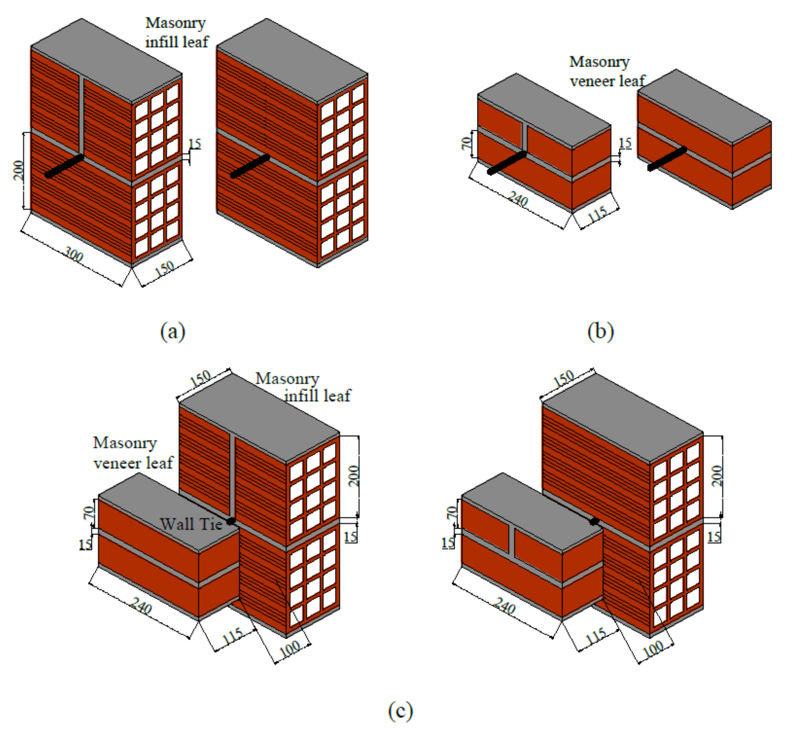
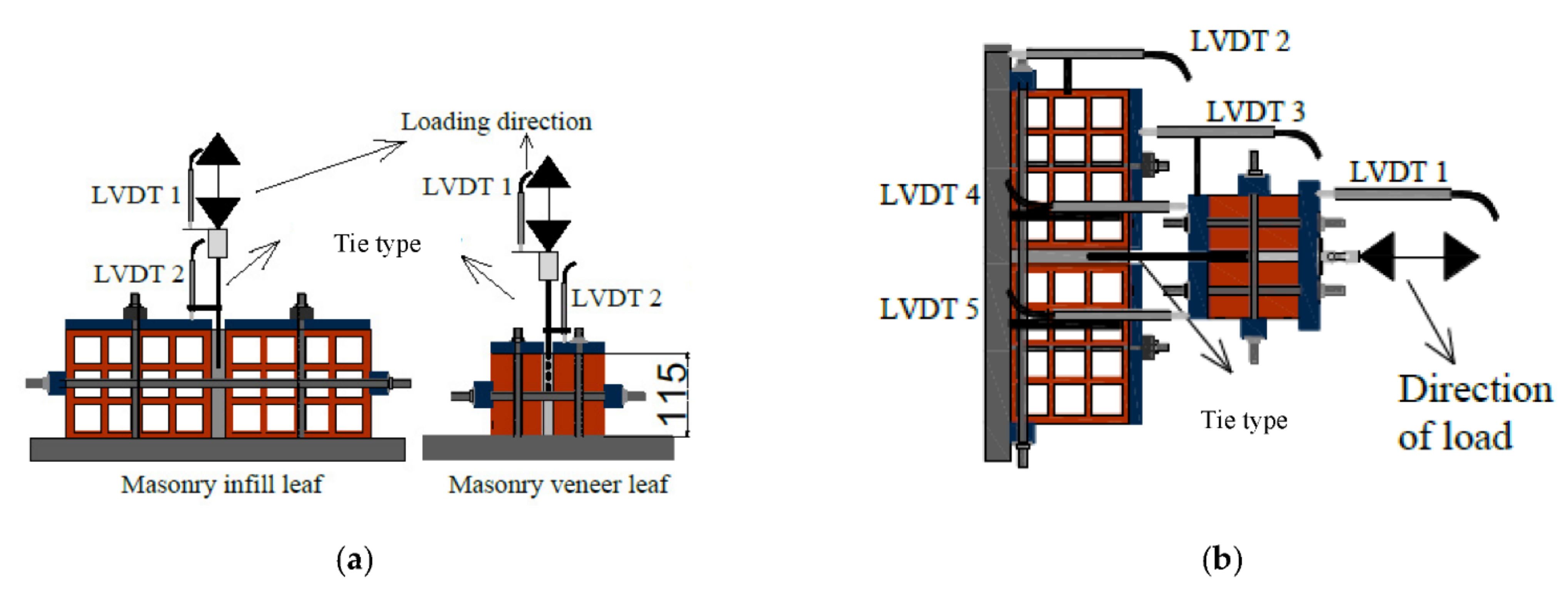
The campaign mainly focused on evaluating the tie-mortar interface and, for that purpose, brick masonry prisms of two bricks and one horizontal joint were built (
Figure 4). They represent common masonry infills (
Figure 4a) and veneer walls (
Figure 4b). One end of the tie was embedded at the horizontal (bed) joint and the other end was left free. The load was applied at the free end in the direction parallel to the load, through tension–compression cycles. Another specimen was prepared simulating a complete assemblage with the masonry veneer prism attached to the masonry infill prisms through ties (
Figure 4c). In these complete assemblages, an air cavity thickness of 100 mm was considered. The cyclic load was applied on the veneer prisms in the same direction parallel to the tie aiming to simulate the common role of ties by transferring the out-of-plane lateral loads to the backing system. The embedment length of the tie is 60 mm in the infill brick masonry prism and 65 mm in the veneer masonry prism.
The experimental setup is shown in
Figure 5. The masonry prisms were confined through steel plates connected by means of steel rods to prevent the movement of the specimen. Vertical confinement was also applied to the prisms to simulate building conditions (approximately 3% of the compression strength of masonry units). After that, tension–compression cyclic loads with cycles of increasing amplitude were applied. Specifically, the displacement imposed in the first cycle was 2 mm; then, the cycles were subsequently increased 1 mm up to a total of 12 mm, when the tests were stopped. Each cycle was repeated to record strength and stiffness degradation. As previously introduced, the load was imposed directly to the tie in case of single assemblages and to the brick veneer prism in case of complete assemblages. For each configuration, six specimens were tested.
A comprehensive description of the results of the experimental campaign is provided in Martins et al. [
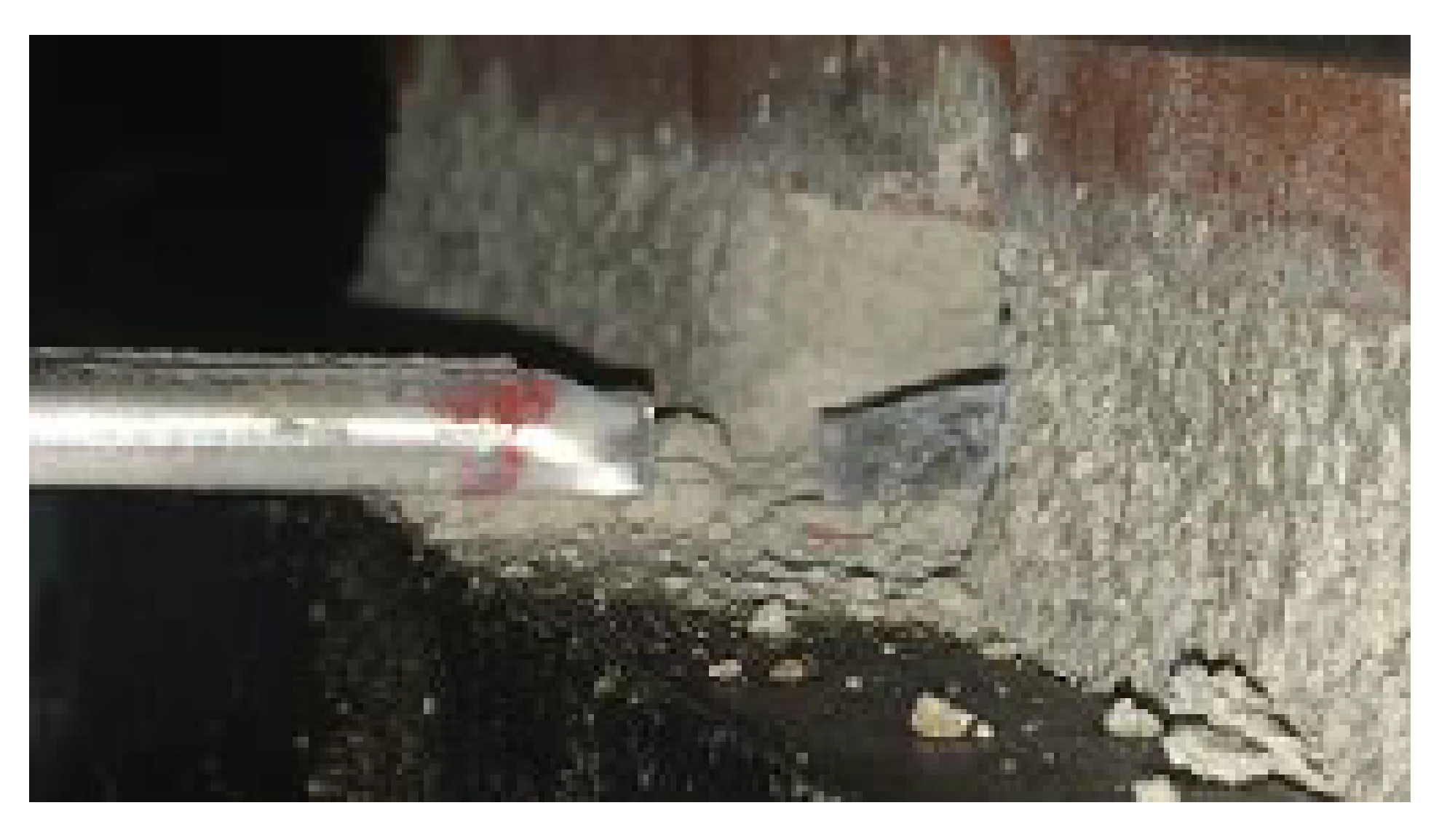
14] and Martins [
34]. As a summary, the failure modes observed for this type of tie during the tests included tie pull-out due to sliding and combined sliding with cone failure of the mortar surrounding the tie, as well as tie buckling and tie fracture at both the middle length and at the interface of the mortar joint.
Figure 6 shows an example of a failure mode reported during the experimental campaign, consisting of the tie fracture at the interface of the mortar.
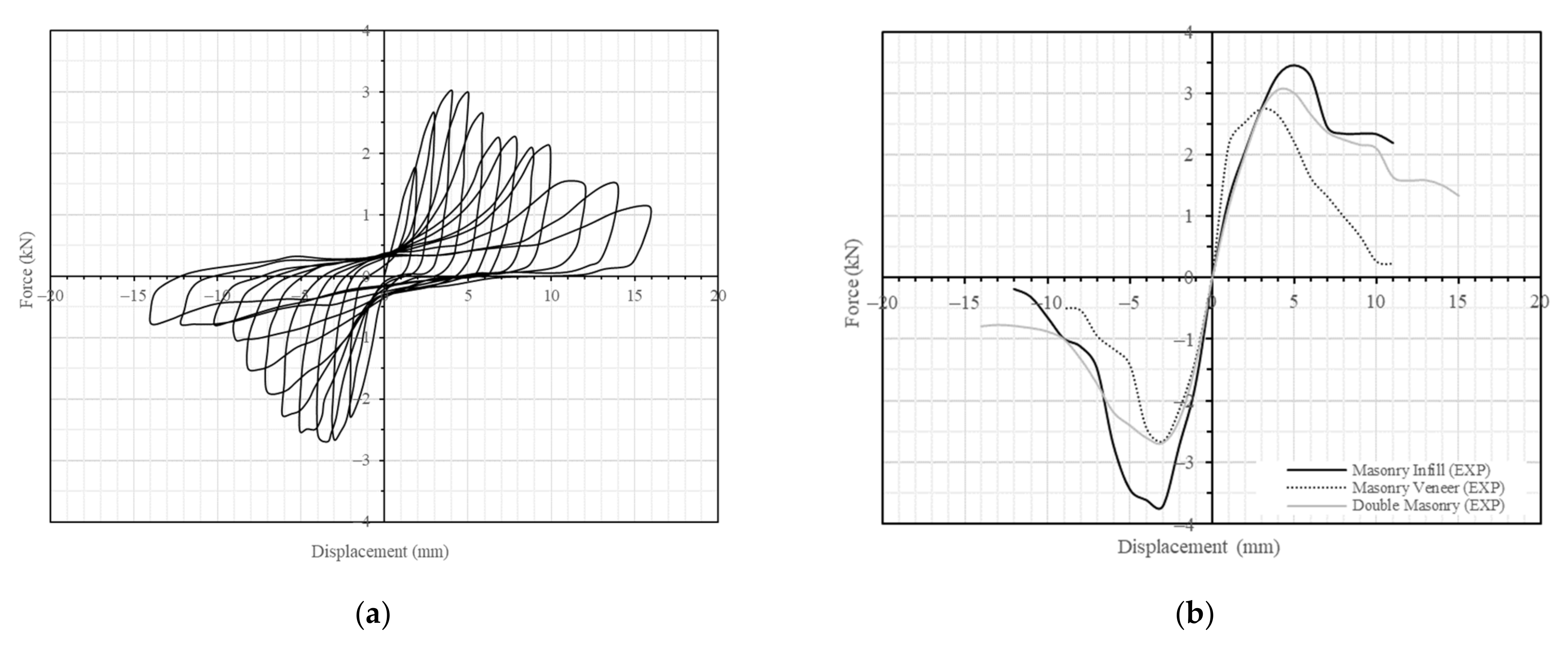
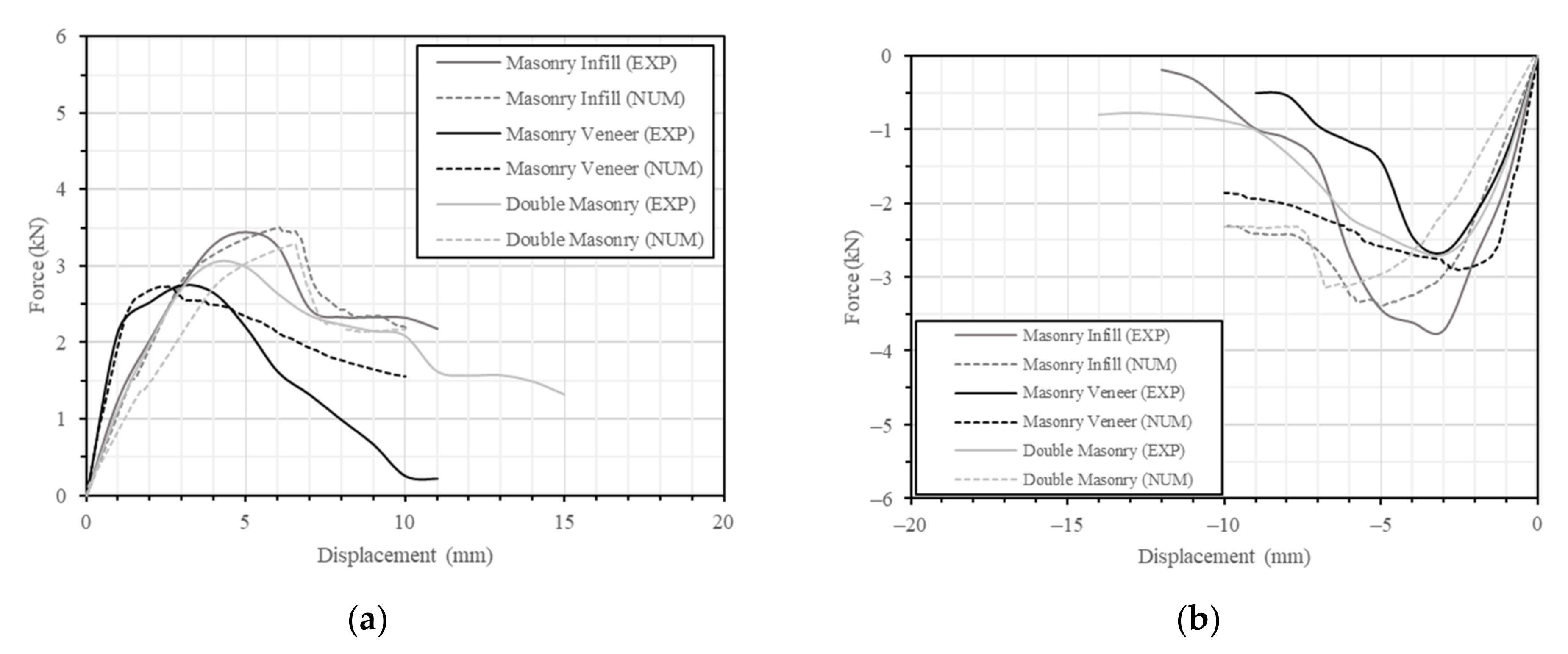
The average load–displacement diagram obtained in the tension–compression cyclic tests of the complete assemblages is shown in
Figure 7a. Monotonic envelopes could also be prepared for a better comparison of the behavior for different test configurations.
Figure 7b shows the envelope curves constructed using the first cycle for the single and complete assemblages. As previously stated, a combination of different failure modes was observed during the test. It was also noted that almost no damage was observed until maximum compression and tensile load was achieved. Typically, the maximum tensile load corresponds to tie pull-out from the mortar joint and the maximum compressive load is associated with tie buckling.
4. Numerical Modeling of the Tie Connection
The present work proposes to use numerical modeling to simulate the tension–compression behavior of the steel tie-brick masonry connections, namely through experimental force-displacement curves. Numerical models were thus built to replicate the different test specimens used in the experimental campaign. The present section discusses the modeling assumptions and the results obtained. In the end, the results are compared with the ones obtained from the experimental enabling to validate the proposed numerical approach.
4.1. Model Geometry and Material Properties
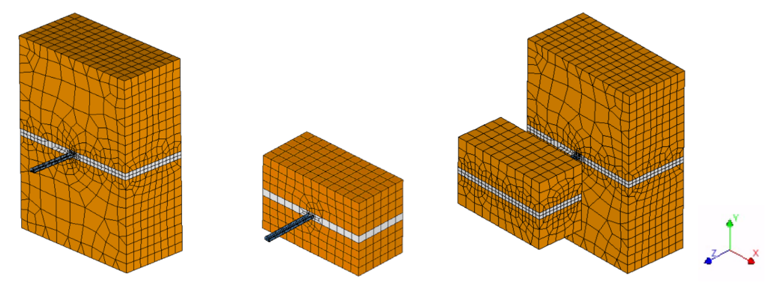
The numerical model aimed to replicate the test setup, boundary conditions and procedure used in the tension–compression tests of the tie connections. The masonry prisms are discretized into the two constituents (brick and mortar). The tie is embedded within the mortar and the connection is modelled using interface elements. In summary, the model has four main components: (a) the brick units; (b) the mortar joint; (c) the tie; and (d) the interface between tie and mortar (
Figure 8).
The overall geometry of the tie was slightly simplified with respect to the real one shown in
Figure 2. The cross-section of the tie is assumed to be constant and has the same dimensions of the cross-section of the central part of the real tie. The U-shape cross-section has a width of 12 mm, a height of 5.5 mm and a thickness of 0.5 mm. The clamp-shaped extremes of the tie were neglected, assuming the same cross-section along the whole length of the tie, for simplification purposes. The embedment length of the tie within the masonry is the same of the experimental tests, being 60 mm in the infill brick masonry prism and 65 mm in the veneer masonry prism. The total length of the tie is 225 mm, resulting in the 100 mm gap between the prisms of the complete assemblage (
Figure 3).
Following also the test setup and procedure (
Figure 4), the boundary conditions and loads are also determined. First, the model is supported at the bottom. Only the translation in the direction parallel to the tie (Z) is restricted. A confinement load is applied in the two surfaces perpendicular to the Y direction. The same confinement load applied in the experimental tests indications was applied (3% of the compressive strength of the masonry). After the application of the load, the movement in Y direction is restricted in both sides. Additionally, the movement of the top part of the bricks in the Z direction is restricted, allowing only the mortar area to deform. Finally, the load is applied incrementally at the free end of the tie. The main difference between the numerical and the experimental analysis is the fact that the load is applied monotonically in the numerical analysis, as an imposed displacement until a total of 10 mm using steps of 0.05 mm. In the experimental tests, cyclic tension–compression loading is applied.
Regarding the material properties used in the numerical model, most of them were extracted from the experimental characterization carried out for the bricks, mortar and tie. The properties are shown in
Table 1. For the steel tie, a simple nonlinear model considering Von Mises and Tresca plasticity is assumed with a yield stress of 350 MPa.
The material model adopted for mortar and brick units is the total strain rotating crack model, assuming a nonlinear post-peak compressive behavior characterized by a parabolic stress–strain relationship and by exponential softening for the tensile behavior. The compressive strength of the mortar and bricks were characterized experimentally, as previously discussed. Poisson’s ratio is kept fixed as 0.15 (typical values may range between 0.1 and 0.2), and the density of the different materials are obtained from the experimental characterization and manufacturer’s information. The rest of the material properties are computed based on the compressive strength.
Tensile strength (f
t) is estimated as 10% of the compressive strength. The elastic modulus (E) is taken as 1000 fc as proposed by Eurocode 6 [
38]. Recommendations by Angelillo et al. [
39] are followed for determining the values of fracture energy: a general value of 0.02 N/mm is assumed for the tensile fracture energy (G
fI) and a ductility index of 1.6 mm is used to calculate the compressive fracture energy G
fc (G
fc = 1.6 f
c). However, it is noted that the initial value assumed for the compressive fracture energy (G
fI) of both infill and veneer masonry mortars had to be reduced 5 times to match the experimental results.
With respect to the interface properties, a Coulomb friction model is adopted for the nonlinear behavior of the interface. The material properties necessary to define the interface material model were calibrated. The initial values were assumed from the experimental load–displacement curves and calibrated through a trial-and-error process.
4.2. Results and Discussion
Figure 9 shows the numerical force-displacements curves obtained and compared with the experimental ones. The numerical curves in tension (
Figure 9a) matches reasonably well the experimental results both in terms of peak load and stiffness. Greater differences can be observed in the post-peak behavior. Nevertheless, the numerical results capture the reduction in strength after reaching the peak. It is also noted that, in terms of damage and failure mode obtained, the numerical model also captures well the experimental results.
The failure mode seems to be a combination between the sliding of the tie and the cracking and failure of the mortar surrounding the tie. Cracking starts early, for lower values of imposed displacement (d), initiating at the areas surrounding the tie.
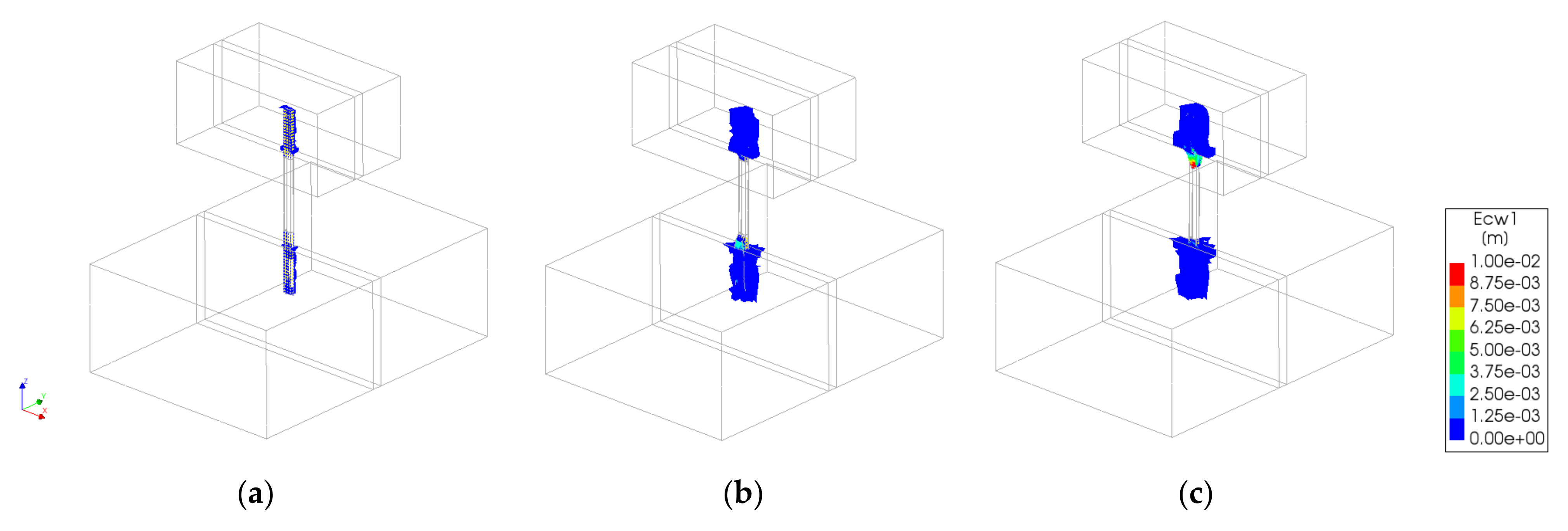
Figure 10 shows the damage evolution for the numerical model simulating the complete assemblage. Damage progressively increases through the mortar area. At the end of the analysis, the area enclosed by the U-shaped cross-section of the tie fails, which seems to agree with the failure observed in the experimental results (
Figure 6).
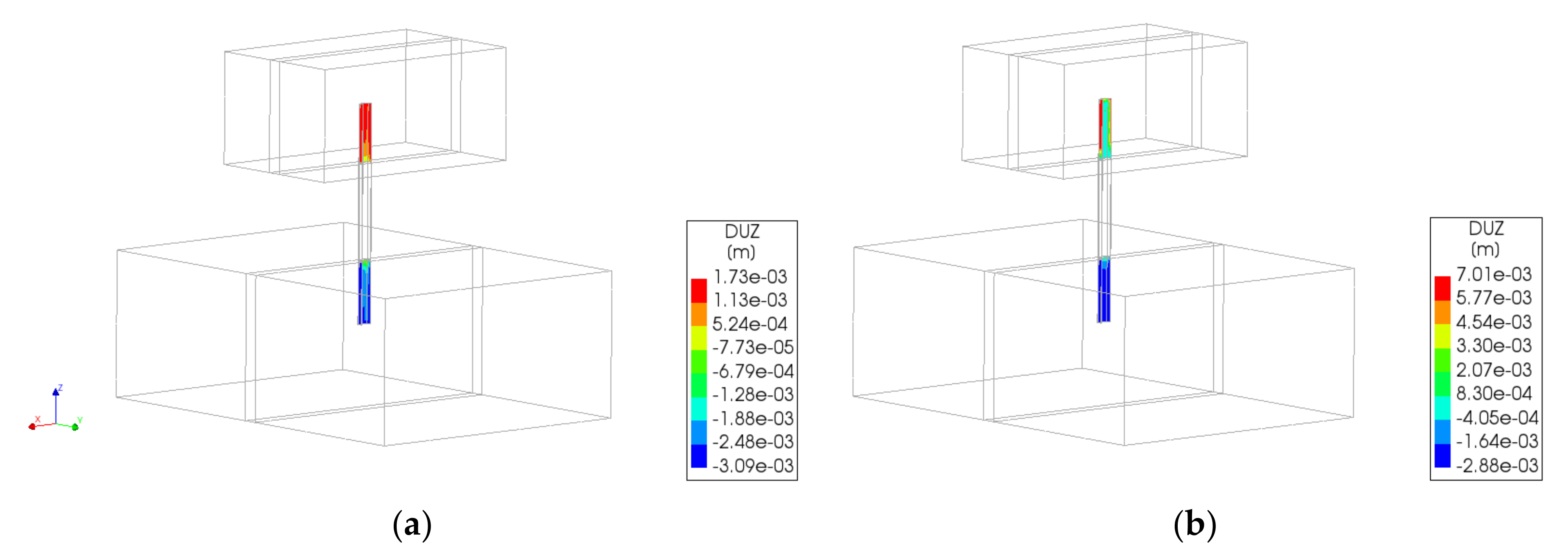
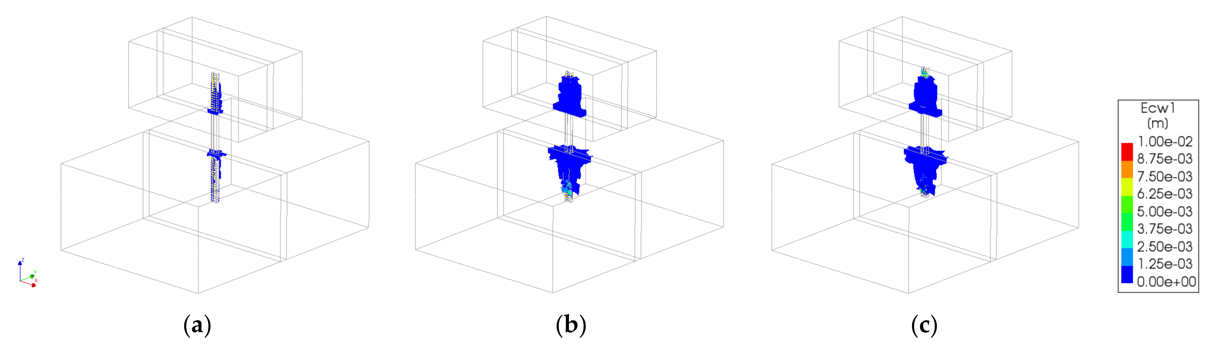
Results at the interface show that sliding of the tie occurs simultaneously to the failure of the masonry surrounding the tie.
Figure 11 shows the evolution of relative displacements of the interface elements at peak load and end of the analysis. The displacements are higher in the exterior surfaces of the tie, illustrating the sliding of the tie. However, in the interior surface of the U-shaped tie, the relative displacements at the interface are reduced because the masonry is heavily cracked in that area. This shows that the failure mode is a combined sliding-cone failure of the mortar surrounding the tie, forming a shallow cone type of failure.
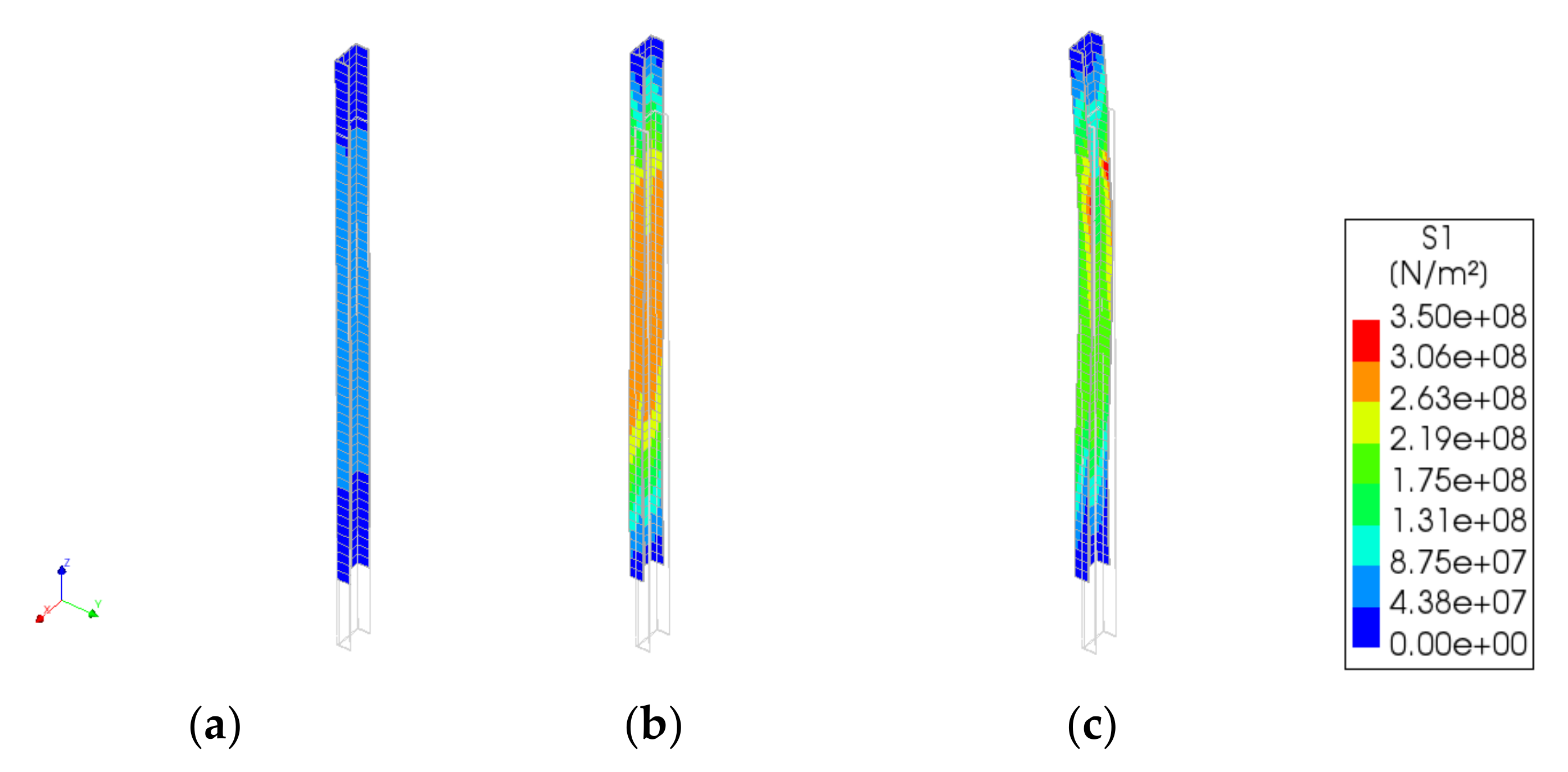
There are also high stresses developing in the tie at peak load (
Figure 12). For example, in the case of the numerical model simulating the complete assemblage, localized tensile stresses are close to the yield stress considered for the steel at the end of the analysis (f
y = 350 MPa). Therefore, the model seems to be able to capture the different failure modes that were reported during the experimental campaign in tension: tie pull-out due to sliding and combined sliding with cone failure of the mortar surrounding the tie, as well as tie buckling and tie fracture.
In compression, the numerical curves show greater variations with respect to the experimental ones (
Figure 9b). The stiffness of the experimental tests is lower than the numerical in the case of the brick masonry veneer and higher in the case of the brick masonry infill. This may indicate that the experimental tests show a slightly different behavior in tension and compression, which is not well captured by the simplified numerical model. This is probably due to the model not being able to simulate the buckling of the tie that was observed in most cases experimentally. Even though the numerical model considers the geometrical nonlinearity, it does not consider possible common imperfections that may cause the buckling of the tie during the experimental tests. The failure obtained in all cases is still a combination between the sliding of the tie and the cracking and failure of the masonry surrounding the tie (
Figure 13). Thus, the model does not seem to capture the buckling failure that was observed experimentally. Nevertheless, in terms of maximum load, results are similar with differences below 10%. Regarding the post-peak behavior, the numerical results are not able to simulate the sudden decrease in strength after the peak load.
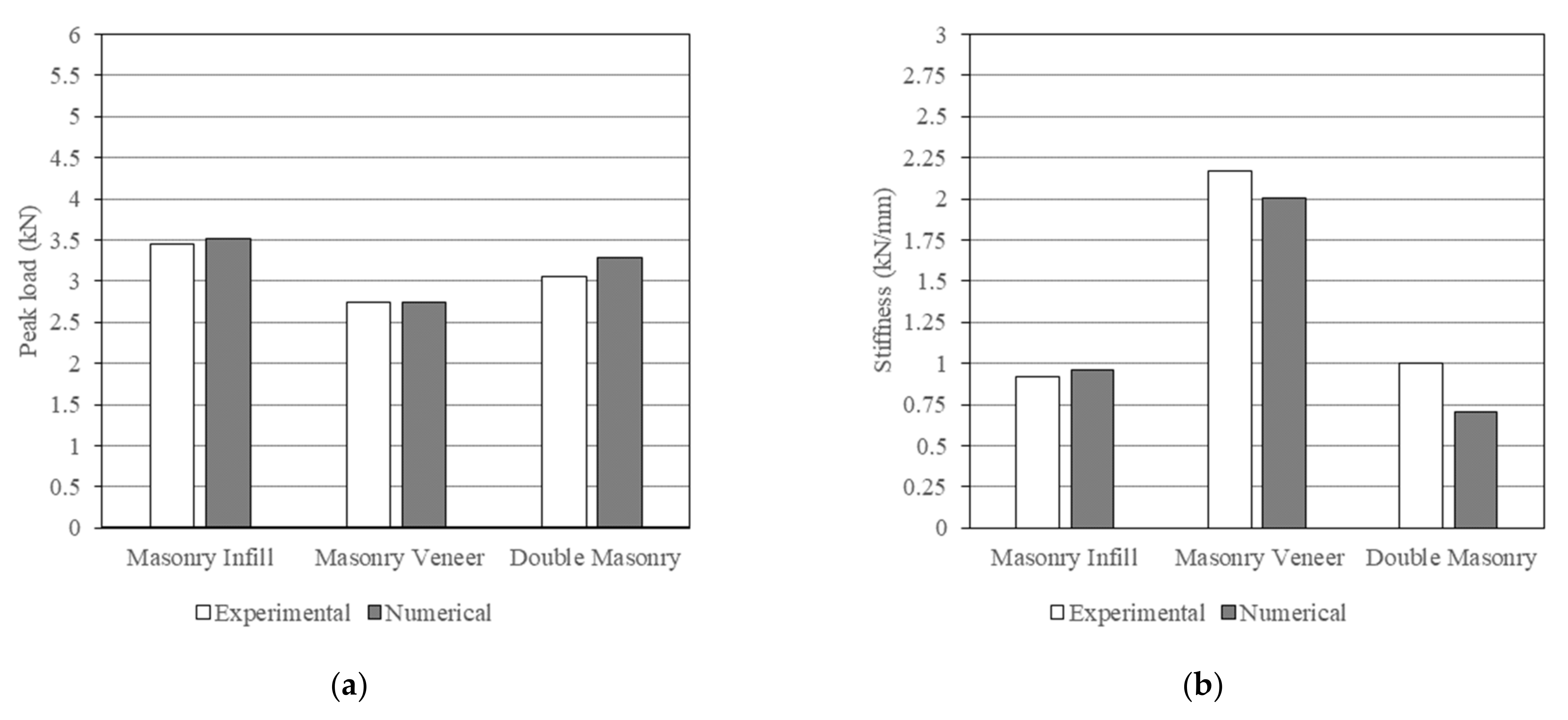
As a summary,
Figure 14 and
Figure 15 show a comparison between numerical and experimental results in terms of peak load (a) and initial stiffness (b) in tension and compression, respectively. As previously discussed, the results match reasonably well the experimental results in tension (
Figure 14). Maximum difference is in terms of initial stiffness for the complete assemblage, being the numerical one around 30% lower than the experimental one. In compression (
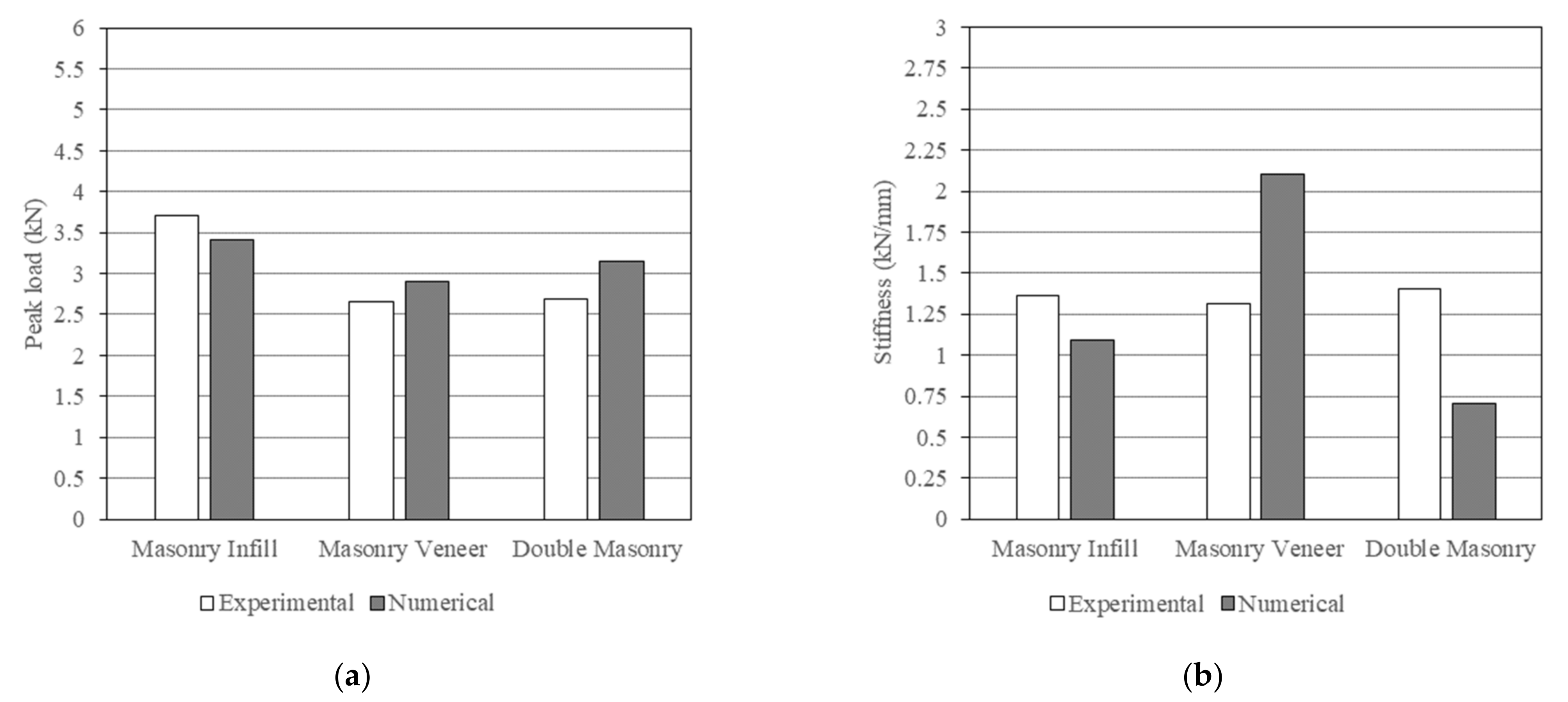
Figure 15), differences are slightly greater in terms of peak load, but are still considered overall low (below 10%). Greater discrepancies are observed in terms of initial stiffness, probably due to the previous mentioned inability to simulate the buckling of the tie.
Finally, it should be noted that only the results of the complete assemblage were shown in detail in the present paper, but the results for the single assemblages are similar in terms of failure modes and evolution of damage. In conclusion, the numerical model is considered to be well calibrated and able to match well the experimental results, namely, in terms of and stiffness and maximum load capacity, validating the numerical approach.
5. Conclusions and Future Work
Steel ties are the most common device to structurally connect veneer walls to the main structural system, thus being responsible for transferring both in-plane and out-of-plane loads that can occur, for example, under seismic loading. The main objective of the present paper was to obtain a better understanding of the structural behavior of ties connecting brick masonry veneers and brick masonry infill walls under horizontal loading. For this purpose, a numerical approach was followed, aiming at simulating the mechanical behavior of a tie connection under tensile and compression, obtained from experimental cyclic tension–compression tests performed on ties embedded in mortar joints of different brick masonry prisms.
The numerical results match well the experimental ones in terms of stiffness and maximum load capacity. Additionally, the evolution of damage and failure modes are also well captured, particularly in tension, consisting of a combination between the sliding of the tie and cracking at the mortar surrounding the tie.
Once the reference model and numerical approach are validated, future work will focus on carrying out a parametric analysis to evaluate the influence of material and geometric properties of the tie and masonry, type of action and construction details. The parametric study can help to develop guidelines for the seismic design and detailing of brick masonry veneer walls and tie connections that can be used in professional practice. Moreover, the better understanding of the structural behavior of these systems obtained after the parametric analysis will be used to developed simplified models that can be used on larger-scale numerical simulations (e.g., buildings or large building components).
It should be finally noted that a better understanding of the structural response veneer walls under seismic load is important for both applying the system on new constructions and for the rehabilitation of existing buildings. Veneer walls can be a suitable solution for façade rehabilitation to improve the thermal and acoustic performance of the existing building stock.
Author Contributions
Conceptualization, J.O., N.M. and G.V.; methodology, J.O., N.M. and G.V.; formal analysis, J.O.; investigation, J.O., N.M. and G.V.; resources, J.O., N.M. and G.V.; writing—original draft preparation, J.O.; writing—review and editing, N.M. and G.V.; visualization, J.O.; supervision, G.V.; project administration, G.V.; funding acquisition, G.V. All authors have read and agreed to the published version of the manuscript.
Funding
The authors acknowledge the support of the Portuguese Foundation for Science and Technology (FCT), through the financing of the research project SEVen—Development of Sustainable Ceramic Brick Masonry Veneer Walls for Building Envelops (PTDC/ECI-CON/30876/2017).
Institutional Review Board Statement
Not applicable.
Informed Consent Statement
Not applicable.
Data Availability Statement
No new data were created or analyzed in this study. Data sharing is not applicable to this article.
Conflicts of Interest
The authors declare no conflict of interest.
References
- Martins, A.; Vasconcelos, G.; Campos Costa, A. Brick masonry veneer walls: An overview. J. Build. Eng. 2017, 9, 29–41. [Google Scholar] [CrossRef]
- Magenes, G.; Bracchi, S.; Graziotti, F.; Mandirola, M.; Manzini, C.F.; Morandi, P.; Palmieri, M.; Penna, A.; Rosti, A.; Rota, M.; et al. Preliminary Damage Survey to Masonry Structures after the May 2012 Emilia Earthquakes, v.1. 2008. Available online: http://www.eqclearinghouse.org/2012-05-20-italy-it/ (accessed on 16 May 2022).
- Ceci, A.M.; Contento, A.; Fanale, L.; Galeota, D.; Gattuli, V.; Lepidi, M.; Potenza, F. Structural performance of the historic and moderns buildings of the University of L´Aquila during the seismic events of April 2009. Eng. Struct. 2010, 32, 1899–1924. [Google Scholar] [CrossRef]
- Papanicolaou, C.G.; Triantafillou, T.C.; Papathanasiou, M.; Karlos, K. Textile reinforced mortar (TRM) versus FRP as strengthening material of URM walls: Out-of-plane cyclic loading. Mater. Struct. 2007, 41, 143–157. [Google Scholar] [CrossRef]
- Bothara, J.; Brzev, S. A Tutorial: Improving the Seismic Performance of Stone Masonry Buildings; EERI: Oakland, CA, USA, 2011. [Google Scholar]
- Martins, A.; Vasconcelos, G.; Costa, A.C. Comportamento sísmico de paredes de alvenaria de fachada-uma breve revisão. In Proceedings of the JPEE-Jornadas Portuguesas de Engenharia de Estruturas, Lisboa, Portugal, 26–28 November 2014. [Google Scholar]
- Memari, A.M.; Burnett, E.F.P.; Kozy, B.M. Seismic response of a new type of masonry tie used in brick veneer walls. Constr. Build. Mater. 2002, 16, 397–407. [Google Scholar] [CrossRef]
- Klingner, R.E.; Shing, P.B.; McGinley, W.M.; McLean, D.I.; Okail, H.; Jo, S. Seismic performance tests of masonry and masonry veneer. J. ASTM Int. 2010, 7, 103–133. [Google Scholar] [CrossRef]
- Brick Industry Association. Technical Notes on Brick Construction 44B: Wall Ties for Brick Masonry; Brick Industry Association: Reston, VA, USA, 2003. [Google Scholar]
- Reneckis, D.; LaFave, J.M. Seismic Performance of Anchored Brick Veneer; Report No. NSEL-016, Newmark Structural Laboratory Report Series; University of Illinois at Urbana-Champaign: Urbana, IL, USA, 2009. [Google Scholar]
- Zisi, N. The Influence of Brick Veneer on Racking Behavior of Light Frame Wood Shear Walls. Ph.D. Thesis, University of Tennessee, Knoxville, TN, USA, 2009. [Google Scholar]
- Okail, H. Experimental and Analytical Investigation of the Seismic Performance of Low-Rise Masonry Veneer Buildings. Ph.D. Thesis, University of California, San Diego, CA, USA, 2010. [Google Scholar]
- Jo, S. Seismic Behavior and Design of Low-Rise Reinforced Concrete Masonry with Clay Masonry Veneer. Ph.D. Thesis, University of Texas, Austin, TX, USA, 2010. [Google Scholar]
- Martins, A.; Vasconcelos, G.; Costa, A.C. Experimental assessment of the mechanical behaviour of ties on brick veneers anchored to brick masonry infills. Constr. Build. Mater. 2017, 156, 515–531. [Google Scholar] [CrossRef]
- Choi, Y.H.; LaFave, J.M. Performance of corrugated metal ties for brick veneer wall systems. J. Mater. Civ. Eng. 2004, 16, 202–211. [Google Scholar] [CrossRef]
- Reneckis, D.; LaFave, J.M. Out-of-Plane Seismic Performance and Detailing of Brick Veneer Walls. J. Struct. Eng. 2010, 136, 781–794. [Google Scholar] [CrossRef]
- Zisi, N.V.; Bennet, R.M. Shear behavior of corrugated tie connections in anchored brick veneer-wood frame wall systems. J. Mater. Civ. Eng. 2011, 23, 120–130. [Google Scholar] [CrossRef]
- Mertens, S.; Smits, A.; Grégoire, Y. Experimental parametric study on the performance of wall ties. In Proceedings of the 9th International Masonry Conference, Guimarães, Portugal, 7–9 July 2014. [Google Scholar]
- Ribeiro, S.; Vicente, R.; Varum, H.; Graça, J.; Lobo, B.; Ferreira, T. Development of retrofitting solutions: Remedial wall ties for masonry enclosure brick walls. In Proceedings of the 9th International Masonry Conference, Guimarães, Portugal, 7–9 July 2014. [Google Scholar]
- McGinley, W.; Hamoush, S. Seismic Masonry Veneer: Quazi-Static Testing of Wood Stud Backed Clay Masonry Veneer Walls. In Proceedings of the Structures Congress 2008: Crossing Borders, Vancouver, BC, Canada, 24–26 April 2008. [Google Scholar]
- Reneckis, D.; LaFave, J.M. Seismic Design of Anchored Brick Veneer. In Proceedings of the 15 WCEE 2012, Lisbon, Portugal, 24–28 September 2012. [Google Scholar]
- Okail, H.O.; Shing, P.B.; Klingner, R.E.; McGinley, W.M. Performance of clay masonry veneer in wood-stud walls subjected to out-of-plane seismic loads. Earthq. Eng. Struct. Dyn. 2010, 39, 1585–1609. [Google Scholar] [CrossRef]
- Liang, J. Development of a Multihazard Resistant Panelized Brick Veneer Wall System. Ph.D. Thesis, Pennsylvania State University, State College, PA, USA, 2006. [Google Scholar]
- Thurston, S.J.; Beattie, G.J. SR189 Seismic Performance of Brick Veneer Houses: Phase 1-Cyclic and Elemental Testing; Research Report; Branz: Judgeford, New Zealand, 2008. [Google Scholar]
- Paton-Cole, V.P.; Gad, E.F.; Clifton, C.; Lam, N.T.K.; Davies, C.; Hicks, S. Out-of-plane performance of a brick veneer steel-framed house subjected to seismic loads. Constr. Build. Mater. 2012, 28, 779–790. [Google Scholar] [CrossRef]
- Okail, H.O.; Shing, P.B.; McGinley, W.M.; Klingner, R.E.; Jo, S.; McLean, D.I. Shaking-table tests of a full-scale single-story masonry veneer wood-frame structure. Earthq. Eng. Struct. Dyn. 2010, 40, 509–530. [Google Scholar] [CrossRef]
- Beattie, G.; Thurston, S. Twenty years of improvement in the seismic performance of masonry veneer construction. Aust. J. Struct. Eng. 2010, 11, 225–229. [Google Scholar] [CrossRef]
- Thurston, S.J.; Beattie, G.J. SR190 Seismic Performance of Brick Veneer Houses: Phase 2-Shake Table Tests on A Clay Brick Veneer Specimen; Research Report; Branz: Judgeford, New Zealand, 2008. [Google Scholar]
- Thurston, S.J.; Beattie, G.J. Seismic Performance of Brick Veneer Houses: Phase 4-Cyclic Racking of A Two-Story Clay-Brick Veneer Building; Research Report; Branz: Judgeford, New Zealand, 2008. [Google Scholar]
- Akhoundi, F. Strategies for Seismic Strengthening of Masonry Infilled Reinforced Concrete Frames. Ph.D. Thesis, Universidade do Minho, Guimarães, Portugal, 2016. [Google Scholar]
- Pereira, P.; Aguiar, J.B.; Camões, A.; Lourenço, P.B. The Portuguese masonry’s mechanical characterization. In Proceedings of the 8th International Masonry Conference 2010, Dresden, Germany, 4–7 July 2010. [Google Scholar]
- Pereira, M.F.P.; Pereira, M.F.N.; Ferreira, J.E.D.; Lourenço, P.B. Behavior of masonry infill panels in RC frames subjected to in-plane and out-of-plane loads. In Proceedings of the 7th International Conference AMCM 2011: Analytical and New Concepts In Concrete and Masonry Structures, Krakow, Poland, 13–15 June 2011. [Google Scholar]
- Akhoundi, F.; Vasconcelos, G.; Lourenco, P.; Silva, L.; Cunha, F.; Fangueiro, R. In-plane behavior of cavity masonry infills and strengthening with textile reinforced mortar. Eng. Struct. 2018, 156, 145–160. [Google Scholar] [CrossRef] [Green Version]
- Martins, A. Seismic Behaviour of Masonry Veneer Walls. Ph.D. Thesis, Universidade do Minho, Guimarães, Portugal, 2018. [Google Scholar]
- NP EN 772-1; Métodos de Ensaios de Blocos para Alvenaria. Parte 1-Determinação da Resistência à Compressão. European Committee for Standardization (CEN): Brussels, Belgium, 2002.
- EN 1015-3; Methods of Test for Mortar for Masonry-Part 3: Determination of Consistence of Fresh Mortar. European Committee for Standardization (CEN): Brussels, Belgium, 1999.
- Ancon. Wall Ties & Restraints Fixings for the Construction Industry; Ancon Building Products: Sheffield, UK, 2016. [Google Scholar]
- EN 1996-1-1; Eurocode 6: Design of Masonry Structures-Part 1-1: General Rules for Reinforced and Unreinforced Masonry Structures. European Committee for Standardization (CEN): Brussels, Belgium, 2005.
- Angelillo, M.; Lourenço, P.B.; Milani, G. Masonry behaviour and modelling. In Mechanics of Masonry Structures; Angelillo, M., Ed.; Springer, CISM International Centre for Mechanical Science: Vienna, Austria, 2014; Volume 551, pp. 1–26. [Google Scholar] [CrossRef]
| Publisher’s Note: MDPI stays neutral with regard to jurisdictional claims in published maps and institutional affiliations. |
© 2022 by the authors. Licensee MDPI, Basel, Switzerland. This article is an open access article distributed under the terms and conditions of the Creative Commons Attribution (CC BY) license (https://creativecommons.org/licenses/by/4.0/).


