1. Introduction
Cold in-place recycling (CIR) of asphalt pavements is a process that has successfully been used for many years [
1]. CIR is a major pavement rehabilitation treatment, consisting of milling the top 50–75 mm of the asphalt concrete (AC) layer followed by in-place cold mixing with asphalt emulsion and stabilizing agents (i.e., Portland cement or hydrated lime), and compacted using traditional methods [
2]. With a more recent focus on sustainability and availability of new emulsions and recycling techniques, CIR continues to be an important pavement rehabilitation tool. However, despite good CIR performance, some engineering properties of this material have not been fully developed.
Traditional rehabilitation techniques for flexible pavements include overlays and mill/overlay. Both of these techniques suffer from the reflection of cracks that exist in the old pavement which limit their service life. In the case of CIR, the high flexibility of the CIR mix offers excellent resistance to reflective cracking while maintaining good resistance to rutting. Other advantages of CIR include the conservation of energy and resources since heating and hauling are not required, therefore energy consumption and greenhouse gas emissions are significantly reduced [
3]. On-site recycling is maximized so off-haul and disposal of old materials is reduced. When used as a base layer, the structural capacity of CIR is considerably better than that of an unbound material. CIR is a relatively quick rehabilitation process with machine production rates increasing. It is a long-term cost-effective treatment with reduced maintenance costs.
There are also some disadvantages of using CIR; it requires an overlay or surface treatment as a wearing course. CIR needs to be constructed in relatively warm and dry weather, therefore limiting the construction season. CIR without stabilizing agents may be susceptible to moisture damage. In-place density during construction is very challenging to measure and low density can negatively impact performance [
4]. When excess Portland cement has been used, CIR has exhibited shrinkage cracking resulting in reflective cracking.
Objective
The objective of this study was to evaluate the structural contribution of the CIR base layer in the flexible pavement structure. The structural contribution was assessed in the form of the structural layer coefficient for the CIR base layer to be used in the 1993 AASHTO Guide for Design of Pavement Structures [
5]. This objective was achieved through mechanistic analyses of flexible pavement structures incorporating engineering properties and performance characteristics of multiple CIR mixtures. The novelty of the research documented in this paper is the development of a structural coefficient for the CIR layer that is based on fundamental mechanistic analyses of flexible pavements. This contribution allows the CIR layer to be incorporated into the structural design process as specified in the 1993 AASHTO Guide, which is widely used throughout the world.
2. Literature Review
The increased use of CIR as a rehabilitation technique has generated interest in properly characterizing the behavior of this material. Investigations have been focused in three areas: (1) mix design, (2) engineering and performance properties of CIR mixtures, and (3) performance of CIR pavements. A review of relevant literature focused on the structural behavior of CIR and, particularly, efforts assessing the cracking behavior of CIR follows.
Morian et al. evaluated the performance of 13 CIR projects in Pennsylvania with service lives of up to 20 years [
6]. The effectiveness of CIR to resist reflective cracking from underlying concrete pavements was evaluated. The research showed that CIR provided two to three times the resistance to reflective cracking compared with conventionally resurfaced control sections. In addition, CIR demonstrated to be a stress-sensitive material, providing increased stiffness in response to increased load. This behavior was indicated to be an important factor in delaying the development of reflective cracking.
Lin et al. investigated the dynamic characteristics of CIR mixtures using engineered asphalt emulsion (CRME) and cement [
7]. Dynamic modulus and phase angle were studied at different curing times. Creep and relaxation tests were performed to determine service conditions at higher temperatures. Fatigue life was evaluated using flexural beam fatigue tests. Cracking characteristics were also evaluated by analyzing fracture interface microstructure with scanning electron microscopy (SEM). The results of this study indicated that CRME is a viscoelastic material based on evidence of time–temperature dependence effects during early and fully cured conditions. According to the Burger model, this material had excellent ability to resist permanent deformation at 60 °C. However, fatigue life of CRME was only 10–20% of ordinary asphalt mixture at high strain, still meeting the requirements for heavy traffic in China’s road structure specifications (>25,000,000 cycle/track).
Gao et al. evaluated the laboratory fatigue behavior of CIR mixtures with digital image correlation (DIC) techniques [
8]. The semicircular bending (SCB) test and indirect tensile test (IDT) were utilized to compare the resistance of CIR and hot mix asphalt (HMA) mixtures to crack propagation in the stress-controlled mode of loading. The results indicated that the addition of 1.5 percent Portland cement to CIR mixtures improved overall fatigue performance life. Under the same stress level, the difference between the two regression lines of fatigue for CIR and AC mixtures was not significant. The SCB test showed that initial stiffness of HMA mixtures was about 1.8 times that of CIR mixtures.
An experimental study of fatigue properties of CIR mixtures manufactured with asphalt emulsion and foamed asphalt was conducted by Yan et al. [
9]. The Nottingham Asphalt Tester (NAT) was used to evaluate the fatigue behavior. Fatigue life was analyzed at 15 °C and four stress levels. The results indicated that foam CIR mixtures displayed greater fatigue life at low stress levels, while emulsion CIR mixtures displayed a greater fatigue life at high stress levels. Qualitative analysis indicated that emulsion CIR mixtures showed plastic fatigue failure due to viscoelastic characteristics, while fatigue damage of foam CIR mixtures showed brittle fracture. The law of vertical displacement and crack development indicated that emulsion CIR mixtures included three states of displacement development before cracking, while foam CIR mixtures included two stages of displacement development before cracking.
The influence of Portland cement on fatigue life of CIR mixtures treated with pozzolanic materials indicating that, given the crystalline nature of pozzolanic bonds, cemented materials tend to be brittle which can reduce flexibility and fatigue life of CIR mixtures, has been reported [
10]. IDT and resilient modulus tests were performed at different temperatures (10 to 25 °C) and curing times (7 to 120 days). Test results showed the effect of cement depends on the initial strain level in the test. At 300 microstrain and above, the addition of cement caused a reduction in fatigue life, while below 300 microstrain the opposite trend was observed.
An assessment of fracture parameters to predict field cracking performance of CIR mixtures was conducted on projects in multiple states [
11]. The ability of fracture parameters to predict field cracking performance of CIR pavements was determined based on the performance of nine projects located in three states. The projects consisted of 2–5year old CIR pavements surfaced with AC overlays. Field pavement performance was assessed based on longitudinal and transverse cracking. Fracture energy was found to be appropriate to differentiate between satisfactory and poor performance. Recommendations included using fracture energy in specifications to optimize the cracking resistance of CIR mixtures.
In addition to laboratory evaluations, several studies have focused on determining the effectiveness of CIR as a reflective cracking control technique. The evaluation of long-term performance of several CIR pavements constructed in Nevada in 1997–1998 was made [
12]. The research concluded that CIR is an effective rehabilitation technique for roads with low and medium volume traffic levels. The results proved that CIR produces a more flexible and stable base course than unbound material, with a greater tendency to reduce the development of reflective and thermal cracking as well as rutting.
Schwartz et al. evaluated procedures for determining material properties of cold-recycled asphalt mixtures for input to structural design and analysis [
13]. Pavement performance as predicted by Pavement ME Design found that well-designed cold recycled materials gave performances comparable to HMA for high traffic volume pavements with appropriate adjustments. Structural analyses conducted with material properties measured as inputs in Pavement ME Design showed sensitivity of the test data to the different stabilizing agents used.
In 2020, Bowers et al. conducted a survey of state highway agency specifications for pavement recycling, including CIR [
14]. The survey identified the following practices: (a) the majority of specifications allow a maximum size of 38 mm with one or two sieves required, (b) density is the most common construction quality indicator, (c) moisture content and curing time are commonly used to identify time for opening to traffic and time to overlay, respectively, and (d) most specifications listed a minimum temperature for the CIR mix at the time of placement.
The most recent research work on CIR mixtures was conducted under the National Cooperative Highway Research Program (NCHRP) Project 09-62 [
15]. This research identified practical test methods that can be used to evaluate the properties of CIR mixtures during construction. The research developed two tests; the short-pin and long-pin tests. The short-pin test was recommended to determine the length of time required prior to opening of the CIR surface to traffic. The long-pin test was recommended to determine the length of time required prior to placing the asphalt concrete overlay over the CIR layer.
As a follow-up to the NCHRP research, Hand et al. evaluated the ruggedness and developed precision estimates for the short- and long-pin tests [
16]. The research concluded that tight tolerances are necessary on pin length and diameter, as well as on pin dullness. The precision estimates recommended a range of accepted results from multi-laboratories, from 7.3% for the number of blows for the long-pin tests to 35–39% for the torque from the long-pin test and the number of blows and torque from the short-pin test.
As can be seen from the review of literature, the majority of the research activities are concentrated around evaluations of the properties of CIR mixtures and the performance of CIR pavements. Hence, there is a gap in the current state of knowledge about CIR mixtures, where the engineering properties of the CIR mixtures can be evaluated but the structural value of the CIR layer cannot be determined. The research presented in this paper attempts to fill the gap by developing a structural coefficient for the CIR layer that can be used in the structural design of flexible pavements.
4. Mechanistic Analysis of CIR Pavements
A mechanistic analysis of the CIR pavement was performed by incorporating the measured engineering properties in terms of dynamic modulus, along with performance characteristics in terms of fatigue and rutting of the evaluated CIR mixtures, into the analysis approach illustrated in
Figure 2.
The determination of the structural layer coefficient for the CIR base layer to be used in the 1993 AASHTO Pavement Design Guide followed the approach listed below:
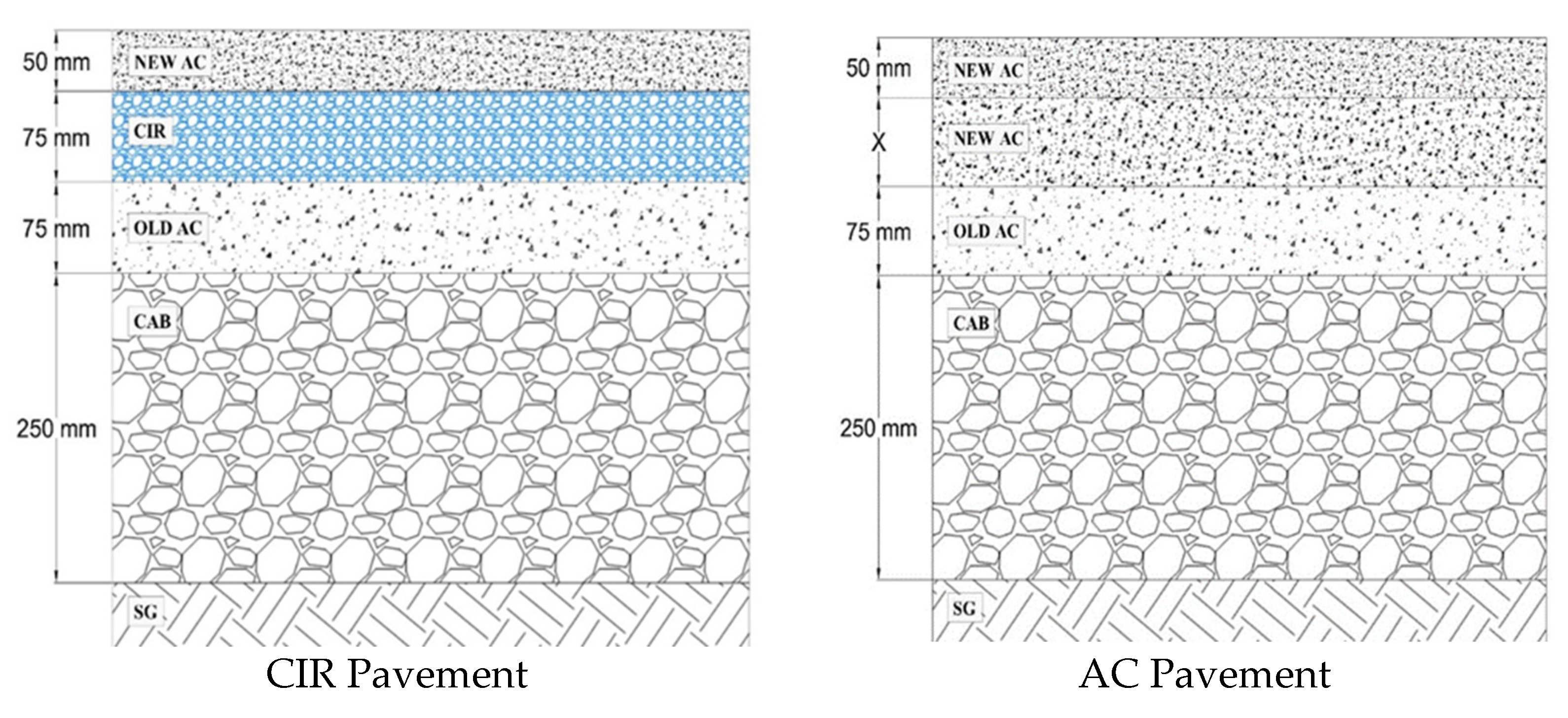
Establish a flexible pavement structure with 75 mm CIR base layer and 50 mm new AC overlay as shown in
Figure 3.
Determine the critical strains for fatigue and rutting performance of the CIR pavement. Use the critical strains to estimate the fatigue and rutting lives of the CIR pavement through the models presented in Equations (2) and (3), respectively.
Determine the required thickness of the new AC layer in the AC pavement underneath the 50 mm new AC overlay, as shown in
Figure 3, to match the fatigue and rutting performance lives for both the CIR and AC pavements.
Determine the total structural number (SN) of the equivalent AC pavement, as determined in step 3, using the known structural coefficients of the various layers in the AC pavement.
Assume that the CIR pavement provides the same SN as the equivalent AC pavement to determine the structural coefficient of the CIR base layer—defined as the product of the ratio of the thickness of AC layer over the thickness of CIR layer times the known structural coefficient of the AC layer.
4.1. Calculation of Pavement Responses
The 3D-Move pavement analysis software was used to determine the pavement responses due to applied load [
21]. The 3D-Move model is based on a finite-layer approach and uses the Fourier transform technique to evaluate the responses of the layered medium subjected to a moving load traveling along the x-axis at a constant speed. The properties of the AC layer can be either linear elastic (i.e., for static analyses such as those conducted in this study) or viscoelastic (i.e., for dynamic analyses). The properties of the unbound layers are linear elastic. Material properties are assumed to be uniform and constant within the layer. The 3D-Move model can handle any number of layers with complex loading at the surface and any number of response evaluation points.
For the purpose of this research, the pavement structure was subjected to the load induced by a single axle with dual tires spaced at 355 mm and a uniform circular load of 20 kN each. The response points were selected under the center of the tire load, the edge of the load, and the center of the dual tires; at the bottom for fatigue and at the middle for rutting of each asphalt bound layer (i.e., CIR and AC).
4.2. Estimation of Equivalent Pavement Structures
The five steps approach described earlier was used to calculate equivalent pavement structures for fatigue performance based on using the fatigue performance models and the tensile strain at the critical locations (bottom of CIR or AC layer). For rutting performance, the approach was based upon using the rutting performance models and a fixed number of cycles to reach an equivalent rut depth in both pavement structures. The Nevada DOT specifies 4.0 mm as the total maximum allowed rut depth in the AC layers.
The following assumptions were made for the analysis. The temperature of CIR was assumed constant and equal to the AC layer temperature at 50 mm below the pavement surface. For the pavement structure rehabilitated with new AC layer and AC overlay, the temperature at 25 mm was selected for the top 50 mm of the AC layer, and the temperature at 50 mm was selected for the remaining depth of the AC layer. Performance models of the new AC layers were obtained from Nevada DOT’s ME-Design database [
22]. Dynamic modulus of the existing AC layer was calculated through Equation (4), using the same master curve assumed for the new AC at corresponding frequency and temperature with a damage value of
dac = 0.6.
where:
= minimum dynamic modulus obtained from fitting the master curve, MPa;
= undamaged dynamic modulus, MPa; and
= damage value, assumed 0.6.
With the properties of each layer, the tensile strains were calculated at the bottom of the CIR layer. The number of cycles to fatigue failure was calculated with the average fatigue performance model presented in Equation (2). The tensile strain required to reach that number of cycles was determined with the respective performance fatigue models for typical AC mixtures in northern and southern Nevada. The final step was determining the required thickness of the new AC layer to match the strain value calculated at the bottom of the CIR layer.
In the case of the rutting analysis, the resilient strains at the middle of each layer were calculated. Using the resilient strain, maximum rut depth, thickness, analysis temperature, and the performance model of each layer, the numbers of cycles (N) to reach the selected rut depth of 4.0 mm were calculated for the CIR pavement. Finally, the required thickness of the new AC layer to achieve the same rut depth (i.e., 4.0 mm) under the same number of load cycles was determined.
4.3. Calculation of CIR Structural Layer Coefficient Based on Fatigue Performance
The final step of the process was to determine the structural layer coefficient for the CIR layer controlled by fatigue performance. Based on the equivalent structure methodology described earlier, it was assumed that the pavement rehabilitated with CIR and the reconstructed pavement with new AC layer have the same SN. The coefficient of the CIR layer was calculated by equating the SN’s of the two pavement structures along with the known coefficients of all other layers in the pavement. Equation (5) was used to determine the structural number of the entire pavement structure.
where:
= thickness of interest layer
= layer coefficient of interest layer
= number of layers excluding the SG
4.3.1. Northern Nevada Pavement Structure
The mechanistic analysis indicated that the tensile strain at the bottom of the CIR layer structure with a PG64-28NV AC overlay was 199 microstrain. This level of microstrain leads to 7,368,742 cycles to failure when used in the CIR fatigue model in Equation (2). The tensile strain required to reach the same number of cycles to failure for a typical mixture in northern Nevada (PG64-28NV) was found to be 201 microstrain. The results indicated that the 75 mm CIR layer is equivalent to 57 mm of the standard AC layer with a PG64-28NV asphalt binder. The fatigue-based layer coefficient was calculated as the ratio of new AC layer thickness (57 mm) over the thickness of the CIR layer (75 mm) times the structural coefficient of the new AC layer (0.35); (57 mm/75 mm) × 0.35 = 0.27.
4.3.2. Southern Nevada Pavement Structure
The mechanistic analysis indicated that the tensile strain at the bottom of the CIR layer structure with a PG76-22NV layer was 198 microstrain. This level of microstrain leads to 22,043,998 cycles to failure when used in the CIR fatigue model presented in Equation (2). The tensile strain required to reach the same number of cycles to failure for a typical mixture in southern Nevada (PG76-22NV) was found to be 187 microstrain. The mechanistic analysis indicated that the 75 mm of CIR layer is equivalent to 50 mm of standard AC overlay manufactured with a PG76-22NV asphalt binder. The fatigue-based layer coefficient was calculated as the ratio of new AC layer thickness (50 mm) over the thickness of the CIR layer (75 mm) times the structural coefficient of the new AC layer (0.35); (50 mm/75 mm) × 0.35 = 0.23.
4.4. Calculation of CIR Structural Layer Coefficient Based on Rutting Performance
Based on the RLT test results and the average rutting model presented in Equation (3), a full mechanistic analysis was conducted for the CIR mixtures. The procedure and assumptions used to study rutting performance were similar to those used to evaluate the fatigue performance. The main difference was that the approach used to determine equivalent pavement structures for rutting performance is based upon using the rutting performance models and a fixed number of cycles to reach an equivalent rut depth in both pavement structures. In this case, the 4.0 mm maximum allowed rut depth in the AC layers specified by the Nevada DOT was used as the failure criterion.
For the purpose of this study, the resilient strains at the middle of each layer were calculated. Using the resilient strain, maximum rut depth, thickness, analysis temperature, and the performance model of each layer, the number of cycles (N) to reach the selected rut depth of 4.0 mm were calculated for the CIR pavement. Then, the required thickness of the new AC layer to achieve the same rut depth (i.e., 4.0 mm) under the same number of load cycles was determined. This analysis used the properties of typical northern (PG64-28NV) and southern (PG76-22NV) Nevada sections.
4.4.1. Northern Nevada Pavement Structure
The mechanistic analysis indicated that the 75 mm CIR layer is equivalent to 215 mm of the standard AC layer with a PG64-28NV asphalt binder. The rutting-based layer coefficient was calculated as the ratio of new AC layer thickness (215 mm) over the thickness of the CIR layer (75 mm) times the structural coefficient of the new AC layer (0.35); (215 mm/75 mm) × 0.35 = 1.00.
4.4.2. Southern Nevada Pavement Structure
The mechanistic analysis indicated that the 75 mm CIR layer is equivalent to 165 mm of the standard AC layer with a PG76-22NV asphalt binder. The rutting-based layer coefficient was calculated as the ratio of new AC layer thickness (165 mm) over the thickness of the CIR layer (75 mm) times the structural coefficient of the new AC layer (0.35); (165 mm/75 mm) × 0.35 = 0.77.


