1. Introduction
Safety in the case of a fire is, after mechanical resistance and stability, the second out of seven Basic Work Requirements (BWR) according to the European Construction Product Regulation (CPR) [
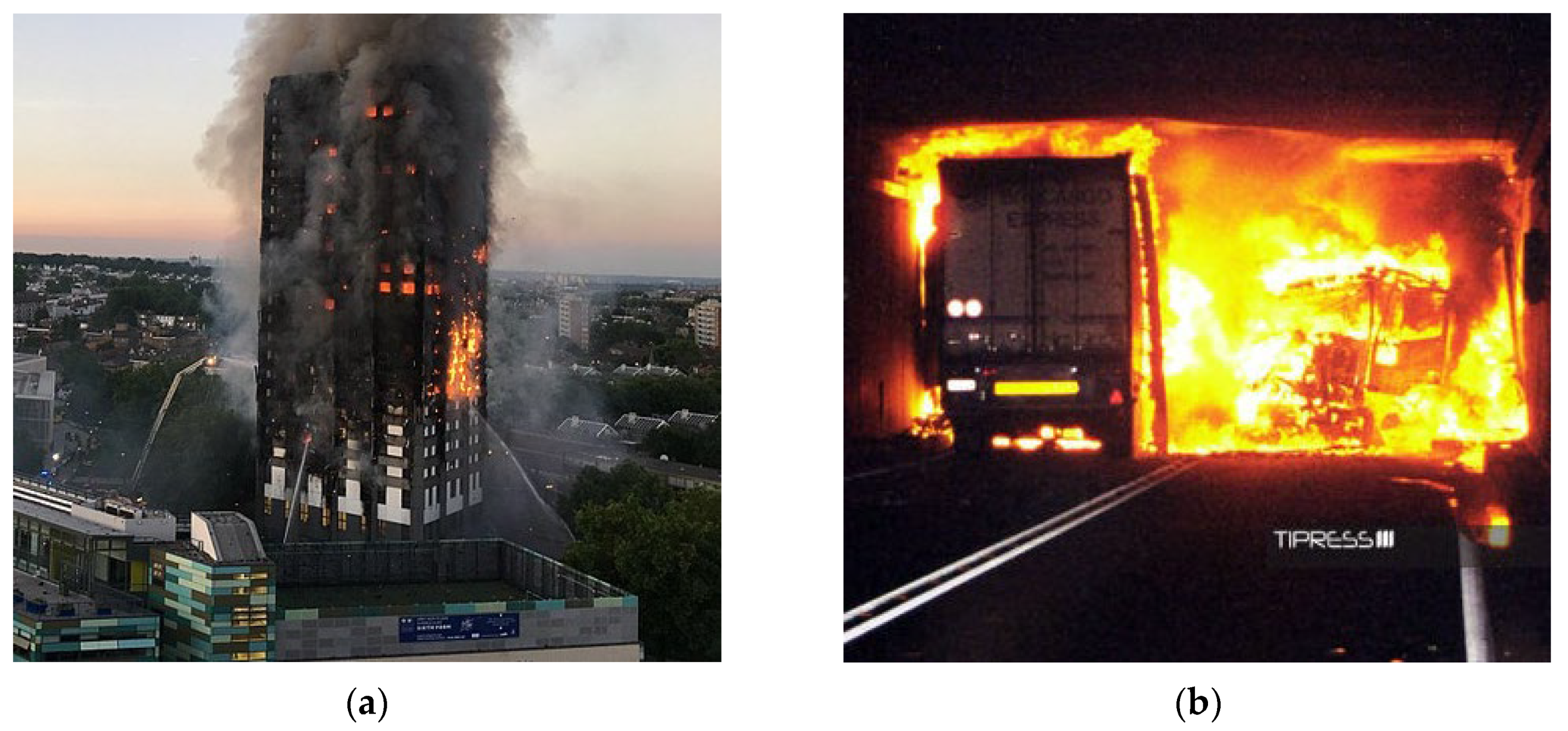
1], demonstrating its key importance for the performance of construction works. Fire events can have devastating results, with many fatalities and tremendous damages. The Grenfell Tower fire in 2017 (
Figure 1a) with 72 deaths and some 70 injured, and a damage estimation of 1 billion GBP [
2], was a wakeup call for all stakeholders to pay attention to fire safety, including the performance of products.
Next to high-rise buildings, tunnels (
Figure 1b) are particularly vulnerable to fire events; and the Mont Blanc tunnel fire in 1999, leaving 39 people dead, is only the most tragic event in a series of catastrophic tunnel fires calling for increased awareness by officials, specifiers, and designers.
The Grenfell Tower fire was caused by a fridge that, due to a malfunction, burst into flames. The fire spread rapidly via the façade made of a flammable external insulation. Next to electrical faults, there are many other potential causes for fires, including deliberate fire raising and accidental gas explosion, but also very often negligence with cigarette butts [
5]. As these risks cannot be fully eliminated, it is important that the risk is controlled by active and passive fire protection. The most prominent active fire protection systems are certainly sprinkler systems extinguishing flames by water. Moreover, fire detection equipment and fire control panels are critical components of the active fire protection. Passive fire protection, on the other hand, aims at containing the fire or slowing its spread, e.g., by fire resistance of structural elements, like columns, walls, and slabs, but also nonstructural elements, like suspended ceilings, raised floors, doors and windows, or façades.
Post-installed mechanical or adhesive anchors are used to connect nonstructural and structural elements to concrete, including components of passive and active fire-protection systems. Post-installed rebars are also used to connect new concrete elements to an existing concrete structure. In any of these cases, the performance of post-installed anchors and rebars plays a crucial role for the fire safety of buildings or other civil works. However, they are still an often-ignored detail, potentially rendering equipment critical to fire safety inoperable or jeopardizing the assumed fire resistance of elements they are connecting.
The material properties undergo major changes as, particularly, the material strength and stiffness drastically reduce with increasing temperatures. Fire resistance is typically demonstrated in fire testing and certified by fire-resistance ratings, where the rating is generally given as a measure of time. The time gives the duration of fire for which no loss in performance occurs, or reduced performance data are given for the respective. Standardization of fire ratings for post-installed anchors and rebars is steadily progressing; however, it is not yet completed. The requirements for fire testing are somewhat confusing, as they have historically been spread over several documents, and everything is yet to fall into place. There are some open technical questions, and, particularly, the bond behavior of post-installed adhesive anchors and rebars is still being investigated. The purpose of this contribution is to provide an overview on fire ratings for post-installed anchors and rebars, and to increase awareness and understanding within the global engineering community for more safety.
2. Background to Classification of Construction Products and Temperature Curves
Fire safety is certainly considered to be critical in all countries with building and safety regulations. In regard to anchor technology, however, fire ratings primarily originate from Europe. As other construction products, post-installed anchors are classified according to EN 13501: EN 13501-1 [
6] classifies construction products by their reaction to fire, e.g., A1 for non-combustible components, the category anchors generally fall into. EN 13501-2 [
7] classifies construction products by their resistance to fire using data from fire tests conducted according to EN 1363 [
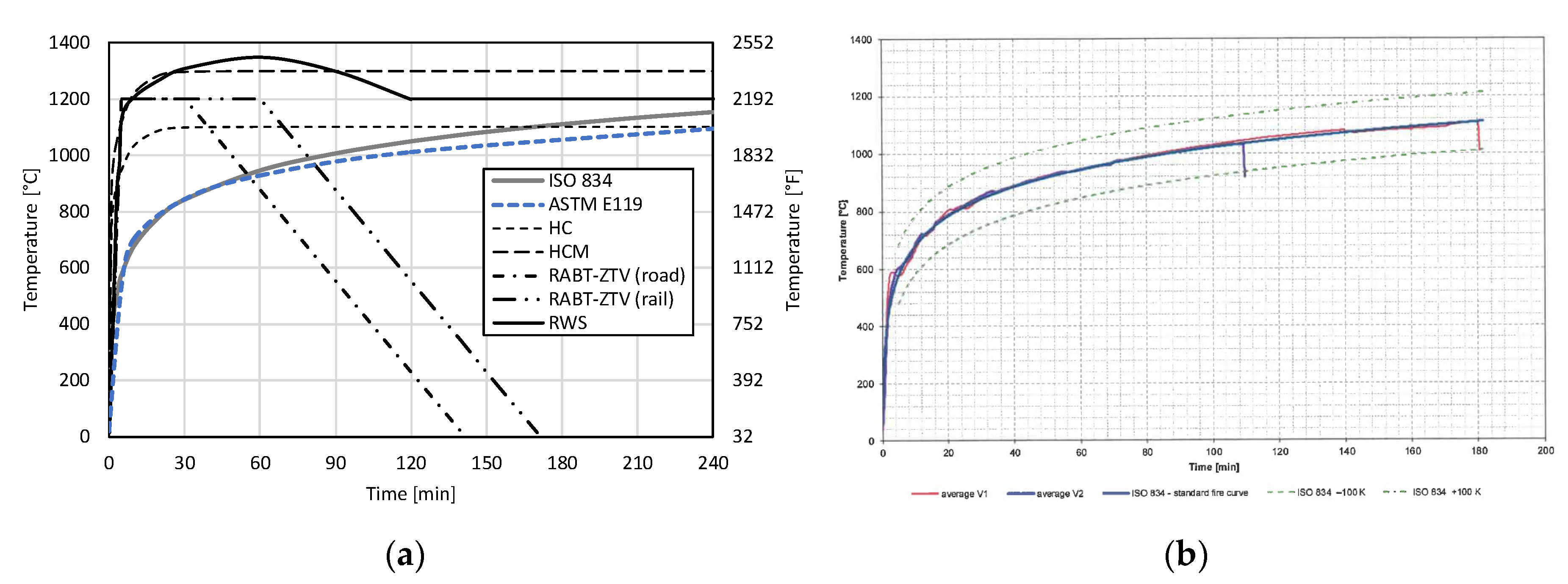
8]. The resistance of the components is related to the duration of the fire exposition given in minutes, typically in 30 min intervals resulting in R30, R60, R90, R120, and R180 classifications. EN 13501 and EN 1363 reference various temperature time curves for furnace testing; the most widely used one is the so-called standard temperature curve (STC) described by the international standard ISO 834-1 [
9] (
Figure 2a).
The STC was developed already in the early 1900s, where wood was the basic fuel source. It therefore represents a solid, or cellulosic, fire and describes the critical fire phase after the flash-over. The curve is characterized by a relatively steep increase of temperature leveling off to reach about 1000 °C after about 90 min. The fire behavior was internationally recognized as representative for fires in buildings. The fire curves described in the US standard ASTM E119 [
11] and in the Canadian standard CAN/ULC-S101 [
12] are nearly identical (refer to
Figure 2a) and within the deviation from ISO curve of +/− 100 K (
Figure 2b) tolerated for testing.
The gasolines emerging in the 20th century led to the development of further fire temperature curves representing liquid, or hydrocarbon, fires particularly relevant for tunnels. Hydrocarbons have higher energy values than cellulosic materials like wood, resulting in curves with an even steeper increase and higher temperatures. Next to the hydrocarbon (HC) curve referenced in EN 1991-1-2 [
13] and its French modification (HCM), there are the German RABT-ZTV(ING) for road tunnel and rail tunnel applications (refer to
Figure 2a). Most internationally known is the Dutch Rijkswaterstaat (RWS) fire temperature curve, with a maximum temperature of 1350 °C after 60 min. Large-scale tests, e.g., in road tunnels [
14] and in rail tunnels [
15], confirmed the applicability of the curves; however, they model an extreme but unlikely fire scenario involving two crashed fuel trucks and are, therefore, not globally required for fire ratings.
3. Fire Rating and Design of Post-Installed Anchors
Post-installed anchors are steel elements anchoring into concrete and designed according to concrete anchor design codes like EN 1992-4 [
16] in Europe or ACI 318 [
17] Chapter 17 in the US. The anchors can be broadly categorized as mechanical anchors (occasionally also referenced as metal anchors) transferring load by mechanical interlock or friction and adhesive anchors (synonymous to chemical or bonded anchors) transferring load by bonding. Plastic anchors are also transferring load by mechanical friction but are treated by separate regulations.
3.1. General Approach as Laid out by EOTA Technical Report TR 020
The Technical Report (TR) 020 [
18] of the European Organisation for Technical Assessment (EOTA) published 2004 is an often-referenced guideline for the evaluation of fire resistance. This report ties into the European Technical Approval Guideline (ETAG) 001 [
19], the then-valid qualification guideline for post-installed anchors, and is aligned with the underlying anchor-design approach in that it considers all possible failure modes and load directions. For each of possibility (i.e., concrete, steel, and pullout failure in tension, as well as concrete, steel, and pry-out failure in shear), a simplified design method based on calculated values for R30 to R120 is provided. For this, the strength data, as reported in the European Technical Assessment (ETA) for cold design, are reduced by reduction factors depending on the design’s fire duration.
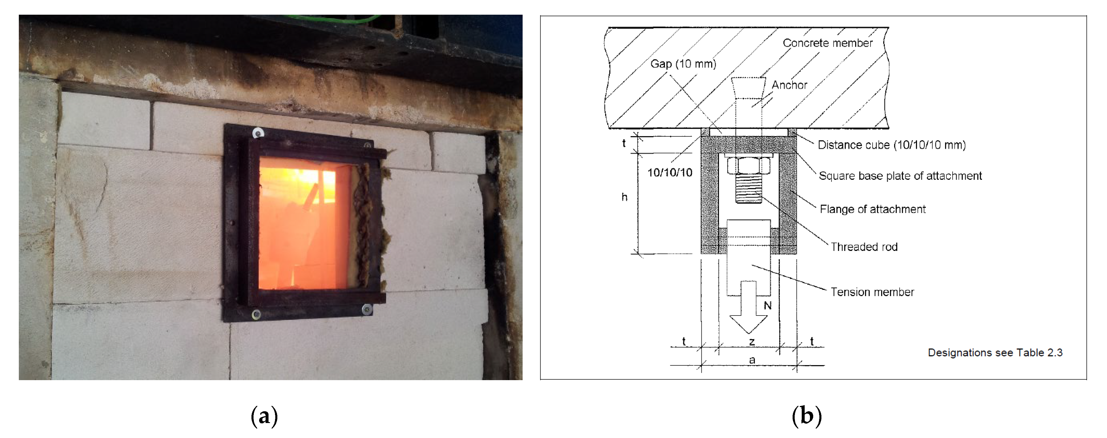
Further, the EOTA TR 020 stipulates details for fire tests conducted to determine, experimentally, the fire resistance in the case of steel or pullout failure. For these tests, anchors are installed in concrete slabs and loaded by weights. These assemblies are mounted in a furnace, then forming its ceiling (
Figure 3a). The concrete slabs are uncracked when testing for steel resistance. When testing for pullout resistance, the anchors are installed in a predefined crack and the fixture is insulated to prevent steel failure. Since the design strength calculated according to the EOTA TR 020 are conservative and the reduction biggest for steel failure, often fire tests are only run to determine the steel resistance (
Figure 3b). The anchors are generally installed as a series loaded by different weights. The duration till failure, i.e., falling down of the specific weights, allows the evaluation of the resistance to fire in kN for fire classifications R30 and above.
The fire test is conducted according to EN 1363-1 [
8], which, in turn, references the ISO 834 STC. The temperature is measured by thermocouples installed in the furnace close to the anchor. EOTA TR020 explicitly does not cover the pullout failure of adhesive anchors. The reason for this is that the resistance in the case of bond failure depends on the temperature gradient along the anchor embedment depth, which is generally variable for adhesive anchors. In the course of the introduction of the European Assessment Documents (EADs), the fire test details stipulated in EOTA TR 020 have been transferred to the respective EAD and the EOTA TR 048 [
21] published in 2016 that provides details for all qualification tests on post-installed anchors, while the design methods have been mostly integrated in EN 1992-4 Annex D.
Note that the current provisions for fire design of anchors only cover the case of resistance during fire. Recent research [
22,
23] has shown that, in the case of concrete breakout failure modes, the residual resistance of the anchors in a post-fire scenario might be affected very strongly due to fire exposure. However, the current codes do not cover the aspects of residual capacity of the anchorage in post-fire scenario.
3.2. Fire Rating as per Current European Assessment Documents (EADs) to Develop Design Values Reported in European Technical Assessments (ETAs) for Post-Installed Anchors
3.2.1. Mechanical Anchors
Already the EOTA TR 020 explicitly stated that the evaluation method presented therein can be used for including fire-resistance data in the ETA for a mechanical anchor. The EAD 330232 [
24] for the qualification of mechanical anchors, published in its first version in 2016, includes the parts of the EOTA TR 020 that are relevant for mechanical anchors and that have not been integrated in EOTA TR 048. EAD 330232 also covers, within BWR2, the reaction to fire which is assumed as being A1 without further testing because of the incombustible metal mechanical anchors are made of.
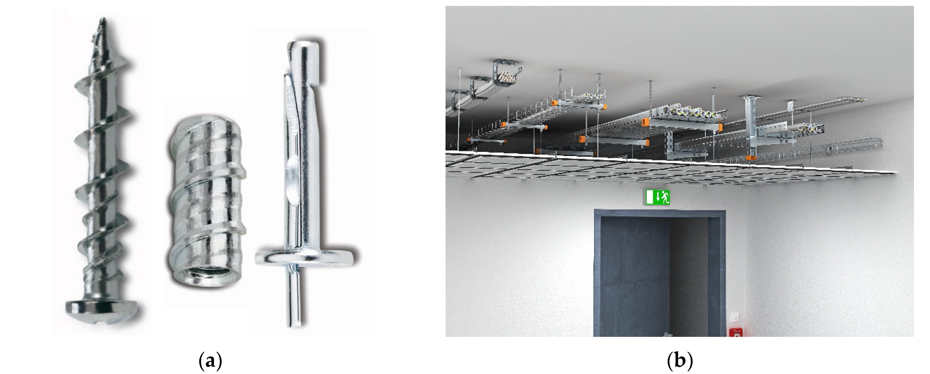
As a result, ETAs of mechanical anchors assessed according to EAD 330232 may include an A1 classification as reaction to fire and design data for fire resistance. Many of these ETAs provide calculated values (example given in Reference [
25]). Some of them provide values that have been improved beyond the calculated values (example given in Reference [
26]) based on furnace testing documented in fire reports (e.g., Reference [
27]). Example anchors and application are shown in
Figure 4.
3.2.2. Adhesive Anchors
As presented above, the EOTA TR 020 does not cover pullout failure of adhesive anchors, and this gap has been preventing fire-resistance data from getting included in an ETA for an adhesive anchor. Moreover, the EAD 330499 [
28] for the qualification of adhesive anchors, published in its first version in 2017, excludes fire performance. It does not cover BWR2 at all, and, therefore, it does not cover the reaction to fire that, for earlier ETAs, was assumed as being A1 for the steel element, as well as the hardened adhesive.
In consequence, fire ratings for adhesive anchors are separate reports. Most of these fire reports contain data for steel failure only, as testing of this failure mode is regulated in EOTA TR 020 (example given in Reference [
29]). Other fire reports contain also data for pullout failure (example given in Reference [
30]) assessed according to the current state-of-the art [
31], which is a combination of experimental fire testing discussed in
Section 5 of this paper.
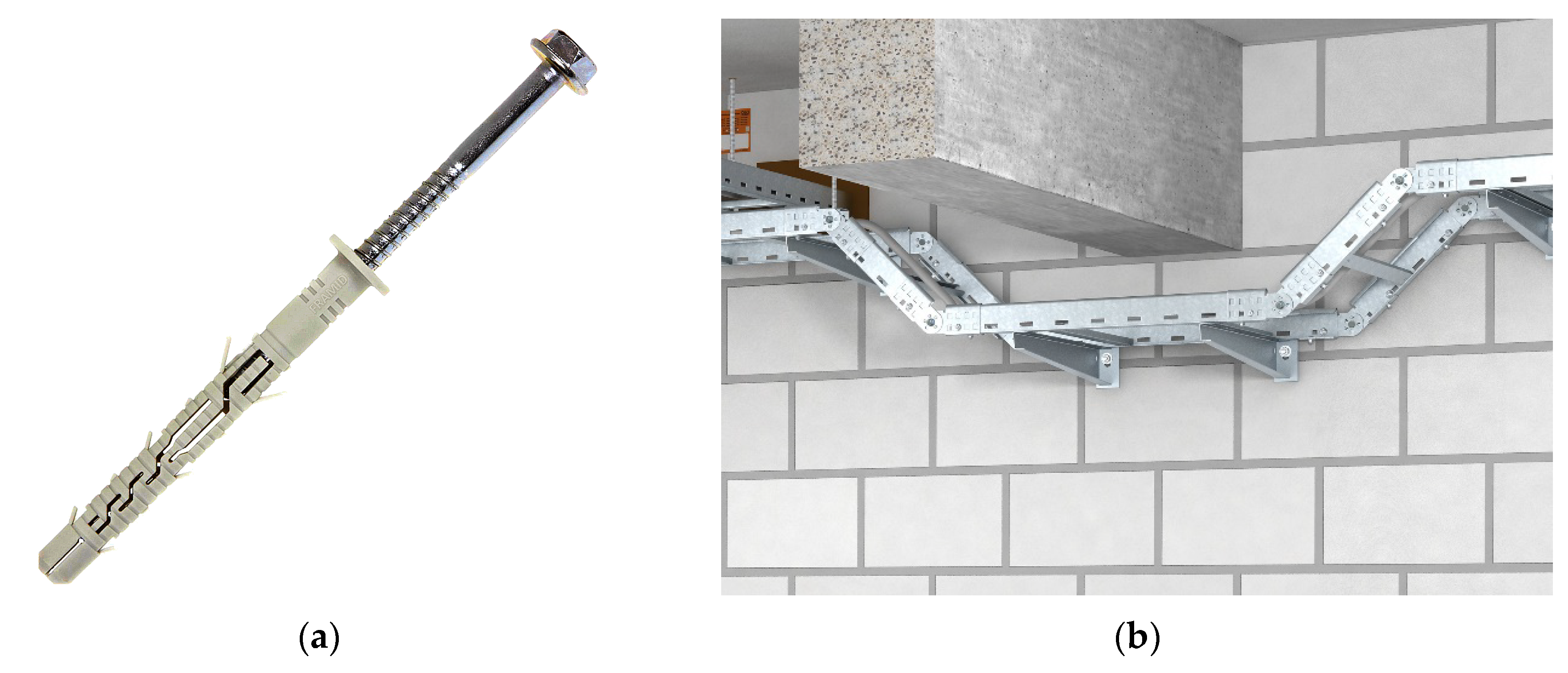
3.2.3. Plastic Anchors
Plastic anchors are often missed in the design process, but they may play an important part in the fire protection of a building, e.g., when they fix trays to walls for cables running between detection equipment and fire control panels. The ignorance of this kind of detail endangered the opening date of the new Berlin airport for several months [
32,
33].
Plastic anchors are covered by the EOTA TR 020, where it is pointed out that the pullout resistance of the anchor may be reduced due to the material strength reduction of the plastic for elevated temperatures. For this reason, the characteristic pullout resistance shall always be determined by fire tests. However, plastic anchors made of polyamide PA6 material with a diameter of 10 mm minimum anchoring 50 mm minimum deep, and a metal screws of 7 mm minimum, have a fire resistance of 0.8 kN for at least 90 min, i.e., R90 (example given in Reference [
34]).
The EAD 330284 [
35] for the qualification of plastic anchors is still in development. The draft covers BWR2; however, the item of the resistance in the case of fire, given as a reference to the EOTA TR 020, was removed from the document in the course of development. It now includes only the reaction to fire, which is A1, without further testing as “in the context of the end use application of the anchorages the plastic material of the anchor embedded in concrete/masonry can be considered to satisfy any reaction to fire requirements”. An example anchor and its application are shown in
Figure 5.
3.3. Fire Design of Post-Installed Anchors according to EN 1992-4
Annex D of EN 1992-4 gives a simplified design method based on the EOTA TR 020. Generally, the fire design is carried out as for the cold design, but using the reduced characteristic strength data. Depending on the required design’s fire duration, the values for R30, R60, etc., can be taken from the ETA. Further, the material safety factors are taken as γM,fi = 1.0, to take into account the fact that fire is considered to be an accidental event, unless otherwise stated in the national annexes.
As previously discussed, there is a gap for the fire rating of adhesive anchors in the case of bond failure, and ETAs for adhesive anchors do not show fire design data yet. It is, however, interesting to note that EN 1992-4 Annex D preventively deals with the fire design of adhesive anchors for which it is stated that the characteristic bond strength, τRk,fi should be taken from the ETA and shall be determined by fire tests. A revision of the EN 1992-4 is, therefore, not required when the era of ETAs that includes fire ratings for adhesive anchors begins.
4. Fire Rating and Design of Post-Installed Rebars
Post-installed rebars (PIRs) are reinforcing bars anchoring into concrete and designed like cast-in reinforcement according to structural concrete design codes like EN 1992-1-1 [
36] in Europe or ACI 318 [
17] Chapter 25 in the US. It is important to note the difference of adhesive anchoring systems occasionally also using pieces of reinforcing bars but designed according to anchor design codes, with substantially higher design bond strengths, resulting in a shallower embedment but a larger minimum edge distance. Meanwhile, PIRs are designed as structural reinforcements and are characterized by a substantially deeper embedment but a relatively smaller minimum edge distance.
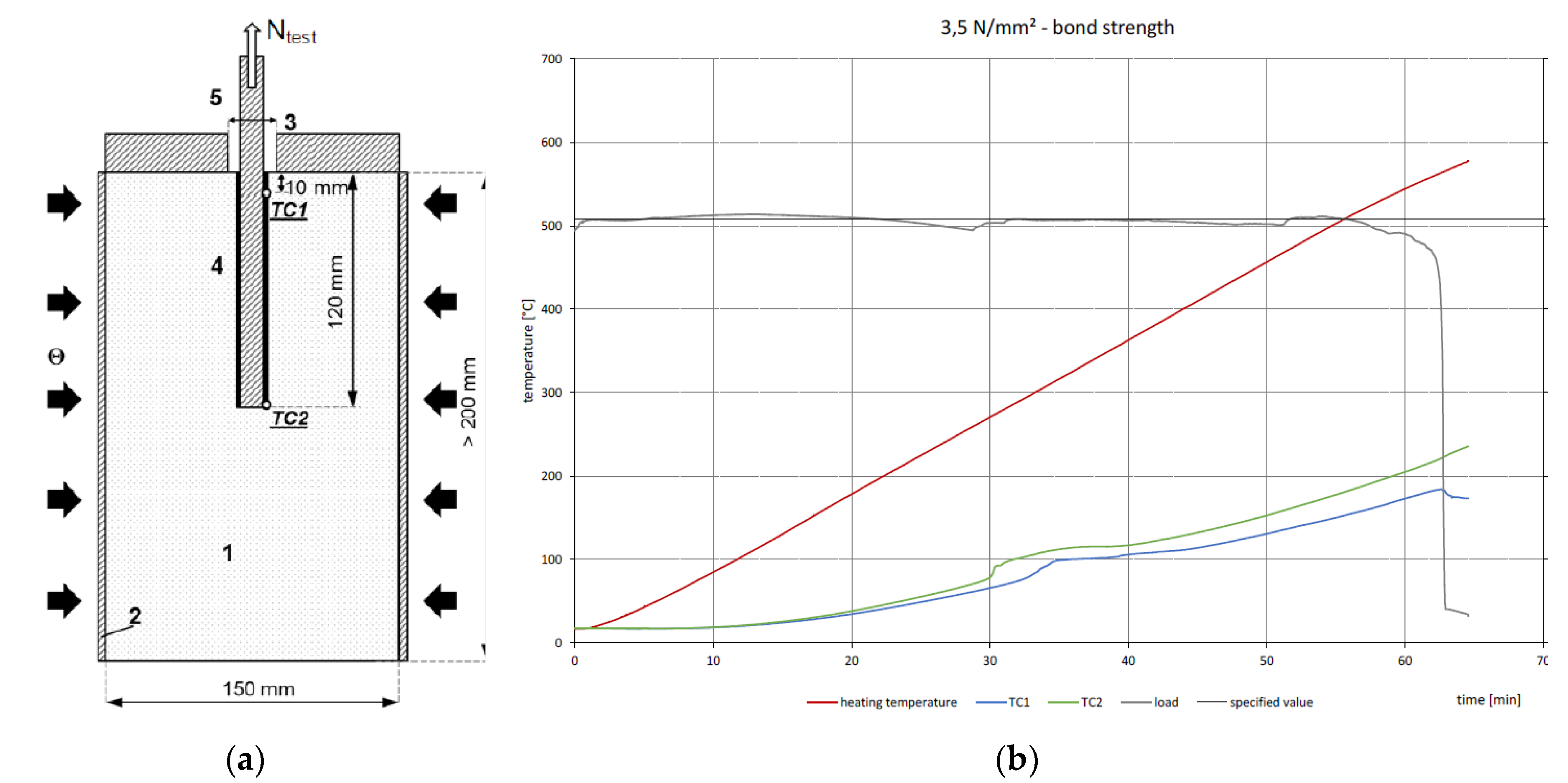
4.1. General Test Approach Using Electrical Heating Sleeves
Since the anchoring of rebars in concrete is designed by determining the required length to develop the force in case of overlap joints (splices) and end anchorages, the bond strength of the adhesive is critical. Other than for anchors, rebars are fully embedded in concrete, without any direct exposure to the fire. For these conditions, independent test labs developed a test setup that allowed them to experimentally investigate the bond strength as a function of the temperature the rebar is exposed to. This test setup consists of a rebar sample installed in a concrete cylinder of defined dimensions, using the adhesive subject of the fire rating (
Figure 6a). While the rebar is loaded by a hydraulic actuator, an electrical heating sleeve applies thermal loading on the lateral sides of the cylinder. Load and temperature at the rebar, measured by two thermocouples, is recorded over time (
Figure 6b). Based on this general test approach, adhesive anchoring systems for PIRs have been assessed to report their fire rating (example given in Reference [
37]).
There are two possible methods to evaluate the strength deterioration of the adhesive in response to increasing temperatures. Either the rebar is loaded to failure after rebar and cylinder are heated to a stabilized target temperature, or a constant load is applied on the rebar while the temperature is gradually increased. The later method of constant load and rising temperature represents, more realistically, the conditions in a structure subjected to a fire, and research has shown that this method yields conservative results [
40,
41]. Therefore, this method is generally used and was introduced as the preferred option in the EAD for the qualification of adhesives used for PIR connections.
4.2. Fire Rating as per Current European Assessment Document (EAD) to Develop Design Values Reported in the European Technical Assessment (ETA) for Post-Installed Rebars
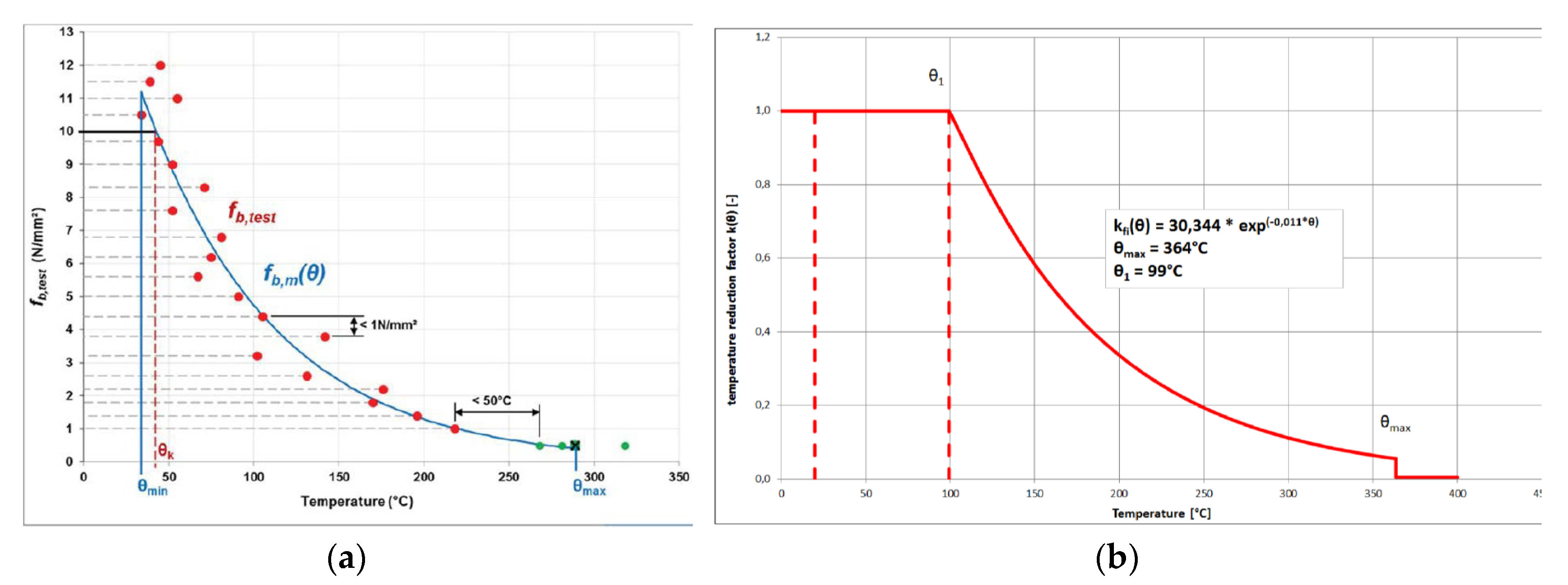
The EAD 330087 [
38] for the assessment of PIR connections with adhesive mortars covers BWR2. As reaction to fire, this adhesive system is classified as A1. To evaluate the resistance to fire, tests with electrical heating sleeves are required. For this, rebars with a diameter of 12 mm are tested in a series, using the constant load method where the temperature is increased by 5 K/min until the load drops, indicating pullout failure. A minimum number of 20 tests at different load levels shall be carried out to plot the bond stress created by the constant load as a function of temperature (f
b,m(Θ),
Figure 7a). The fitting curve is then transformed to a curve representing the strength reduction, k
fi, plotted over the temperature, which is then reported in the ETA document (
Figure 7b).
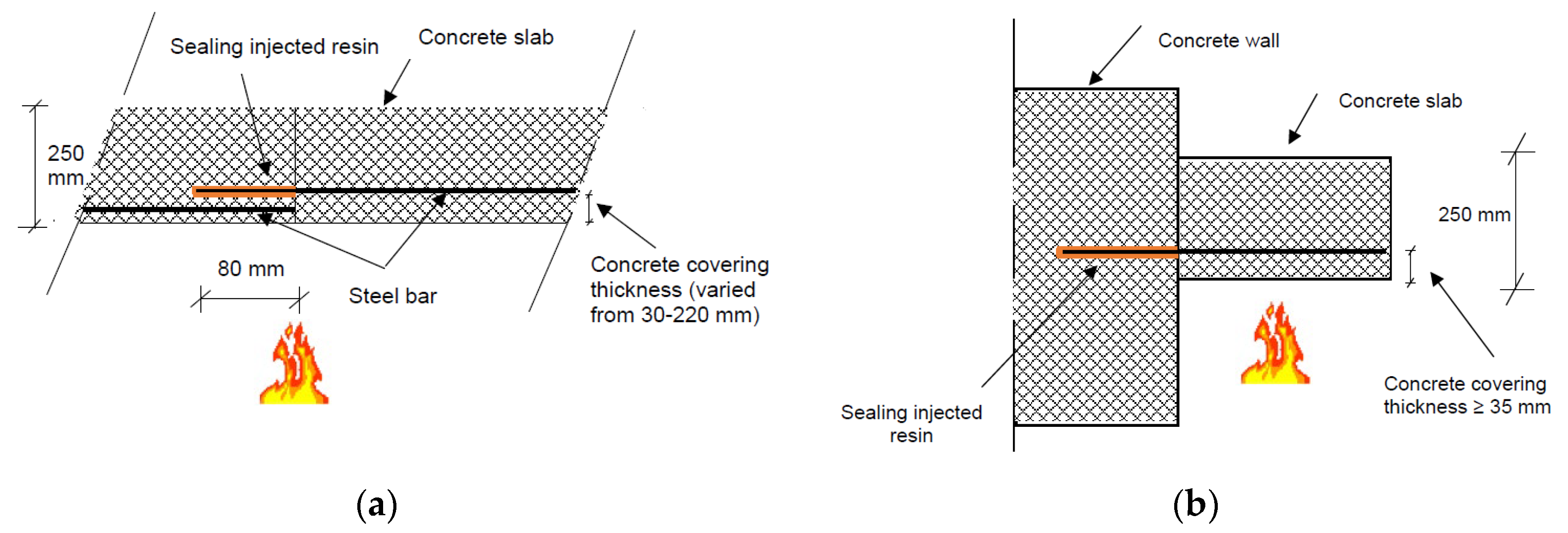
4.3. Thermal Simulation for Application Cases to Develop Fire-Design-Strength Data
The strength reduction function alone is insufficient to carry out the fire design. It merely describes the response of the adhesive to increased ambient temperatures. The temperature depends on the specific application, i.e., the geometry of the concrete structure it is embedded in. By thermal simulations, for example, using finite element method, the temperature profile, over time, for specific model structures can be determined by exposing the structure surface to the ISO 834 STC. The temperature profile, together with the strength-reduction function, then allows us to calculate the bond strength for given fire durations.
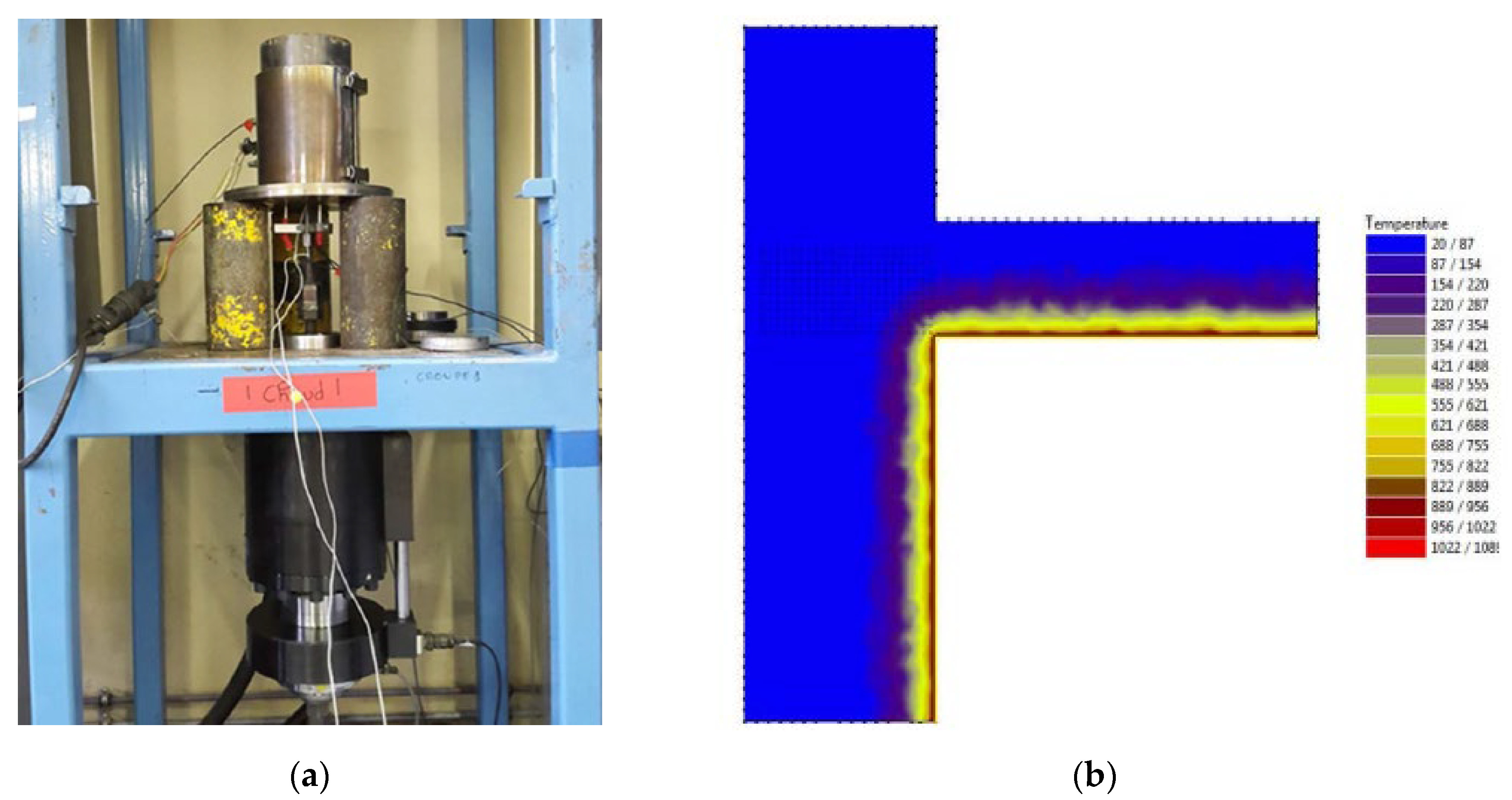
Fire reports complementing the ETAs typically provide fire-design-strength data for the two most common design cases and for fire durations corresponding to R30 to R240. One is the slab-to-slab connection (
Figure 8a), where the temperature gradient is constant along the rebar. In this case, the characteristic bond strength, f
bk, can be given as a function of concrete cover to design the development length of the overlap joint. The other is the slab-to-wall connection (
Figure 8b), where the temperature, as well as its gradient, are decreasing along the rebar with increasing depth. In this case, the characteristic maximum force, N
Rk that the end anchoring can transfer for a given anchorage depth is provided.
4.4. Fire Design of Post-Installed Rebars According to EN 1992-1
The fire design of PIRs follow, in principle, the same design rules as stipulated for the cold design in EN 1992-1-1, but using the reduced characteristic strength data for R30, R60, etc. Further, the requirements given in EN 1992-2 [
43] for the fire design of concrete structures are to be considered, and, as such, the material safety factor is taken as γ
M,fi = 1.0, if not otherwise stated in the national annexes.
Because of the smaller safety factor, the fire-design strength can be higher than the cold-design strength in cases or at temperatures where there is no reduction in strength (compare to the stretch of the reduction curve shown in
Figure 7b, where k
fi = 1.0). Moreover, due to a different evaluation approach, elder fire reports falling back on a strength reduction not developed in line with EAD 330087 may show fire-design-strength data substantially higher than what is defined as maximum today. However, in any case, the critical-design strength is limited by the cold design.
5. Research Closing the Gap
Current research in the field of fire performance of post-installed anchors and rebars is primarily focused on the behavior of adhesive anchoring systems and their bond failure. For post-installed adhesive anchors, the goal is to close the gap in the fire qualification within the EAD 330499, allowing ETAs to cover BWR2 and to provide fire-resistance data. Reichert and Thiele [
44] proposed to use a test and evaluation approach similar to that used for fire rating of PIRs presented in
Section 4.1 of this paper. This approach uses heating tests, in combination with thermal simulations, for variable anchor embedment. The approach has been adopted in a DIBt guideline [
31] and is already used for fire reports, as presented in
Section 3.2.2. Using the same test setup, Lahouar et al. [
45] investigated the mechanical behavior of adhesive anchors by heating tests (
Figure 9a) at stabilized temperature and at constant load, confirming the constant load method as conservative. The results were used as a basis for numerical simulations, using a shear lag model considering bond stress and displacement compatibility along the anchor [
46]. Al-Mansouri et al. used numerical simulations [
47] and experimental tests [
48] to investigate test parameters influencing the evaluated fire resistance.
For PIRs, some of the research aims at standardizing the thermal simulations required to derive fire-design data for PIRs which are, to date, provided in separate fire reports, as presented in
Section 4.3. The critical point is the variability in the geometry of the application. While the geometry of slab-to-slab connections is relatively simple to capture by the thickness of the concrete covering the overlap joint exposed to the fire, the thermal profile for end anchorage in slab-to-wall connections depends on the dimension of the concrete structure and the embedment depth of the rebar. Mucciaca [
49] studied i.a. the mesh discretization and temperature distribution for the slab-to-wall case (
Figure 9b). Experimental tests help to model the heating and to calibrate numerical simulations by predicting the failure behavior. For this, Pinoteau [
50] and Lahouar [
51] conducted large-scale fire tests where a cantilever slab is connected to a wall, using post-installed, and subjected to a ISO 834 (STC) fire.
6. Conclusions
Fire safety is an important performance aspect of structural design and construction works. Fire ratings of construction products are mostly based on fire tests using the standard temperature curve (STC) defined in ISO 834. This holds, in particular, for buildings where cellulosic fires are critical, while, for tunnels, more stringent temperature curves representing hydrocarbon fires may be required.
For post-installed anchors and post-installed rebars (PIRs), fire ratings primarily originate from Europe. The EOTA TR 020 is the most referenced guideline, forming the basis also for the fire rating of mechanical anchors within the relevant European Assessment Document (EAD), whereas the fire rating of adhesive anchors is not fully regulated yet and therefore not included in the European Technical Assessment (ETA) documents. However, promising proposals have been made to close the gap that there is regarding the evaluation of the bond failure for variable depths requiring thermal simulations. This approach is similar to that used for post-installed rebars, where, in addition, the geometry of the concrete structure has to be considered when evaluating the fire resistance.
The design standard EN 1992 Parts 4 and 1 cover conclusively the fire design of post-installed anchors and post-installed rebars, respectively. The consistent system of qualification and design ensures a high level of safety and confidence for specifiers and design professionals. Ongoing research involving large-scale testing further demonstrates the validity of the test parameters underlying the regulations for fire rating of post-installed anchors and post-installed rebars.
Author Contributions
Conceptualization, P.M.; investigation, P.M. and A.S.; writing—original draft preparation, P.M.; writing—review and editing, P.M. and A.S. All authors have read and agreed to the published version of the manuscript.
Funding
This research received no external funding.
Conflicts of Interest
The authors declare no conflict of interest.
Disclaimer
Opinions, conclusions, and recommendations expressed in this paper are those of the authors only and do not necessarily reflect those of the authors’ affiliations or other sponsoring agencies.
References
- Regulation (EU) No 305/2011 of the European Parliament and The Council of 9 March 2011 Laying down Harmonised Conditions for the Marketing of Construction Products and Repealing Council Directive 89/106/EEC 2011. Available online: https://eur-lex.europa.eu/legal-content/EN/TXT/?uri=celex%3A32011R0305 (accessed on 15 September 2020).
- Evans, S. Grenfell Tower Fire Insurance Loss Estimated at up to £1 Billion. Reinsurance News. Available online: https://www.reinsurancene.ws/grenfell-tower-fire-insurance-loss-estimated-1-billion/ (accessed on 19 July 2020).
- Wikipedia: Grenfell Tower Fire (wider view), Cropped Detail; Permission. Available online: https://upload.wikimedia.org/wikipedia/commons/e/e0/Grenfell_Tower_fire_%28wider_view%29.jpg (accessed on 8 October 2020).
- Tipress: San Gottardo—Incidente in Galleria, Cropped Detail; Courtesy Ti-Press/Polizia Cantonale. Available online: https://www.archivio-tipress.ch/item/it/1/59407 (accessed on 8 October 2020).
- Camia, A.; Durrant, T.; San-Miguel-Ayanz, J. Harmonized Classification Scheme of Fire Causes in the EU Adopted for the European Fire Database of EFFIS, Executive Report; Joint Research Centre of the European Commission, Institute for Environment and Sustainability Forest Resources and Climate Unit: Ispra, Italy, 2013. [Google Scholar]
- EN 13501-1: 2018. Fire Classification of Construction Products and Building Elements—Part 1: Classification Using Data from Reaction to Fire Tests; Comite Europeen de Normalisation: Brussels, Belgium, 2018. [Google Scholar]
- EN 13501-2: 2016. Fire Classification of Construction Products and Building Elements—Part 2: Classification Using Data from Fire Resistance Tests, Excluding Ventilation Services; Comite Europeen de Normalisation: Brussels, Belgium, 2016. [Google Scholar]
- EN 1363-1. Fire Resistance Tests Part 1: General Requirements. Available online: https://infostore.saiglobal.com/preview/98705623690.pdf?sku=870500_SAIG_NSAI_NSAI_2069881 (accessed on 15 September 2020).
- ISO 834-1. Fire-Resistance Tests—Elements of Building Construction—Part 1: General requirements. Available online: https://www.iso.org/standard/2576.html (accessed on 15 September 2020).
- MFPA Leipzig Fire Tests on the Screw Anchor “Walldog” According to TR 020 “Evaluation of Anchorages in Concrete Concerning Resistance to Fire” (May 2004) to Determine the Characteristic Bond Strength under Tensile Load; Test Report No. PB 3. 2/18-121-1; 2019.
- Standard Test Methods for Fire Tests of Building Construction and Material; ASTM E119; American Society for Testing and Materials (ASTM), ASTM International: West Conshohocken, PA, USA, 2020.
- CAN/ULC-S101. Standard Methods of Fire Endurance Tests of Building Construction and Materials. Available online: https://www.scc.ca/en/standards/notices-of-intent/ulc/standard-method-fire-endurance-tests-building-construction-and-materials (accessed on 15 September 2020).
- Eurocode 1: Actions on Structures—Part 1-2: General Actions—Actions on Structures Exposed to Fire; EN 1991-1-2; European Committee for Standardization (CEN): Brussels, Belgium, 2002.
- Ingason, H.; Li, Y.Z.; Lönnermark, A. Runehamar tunnel fire tests. Fire Saf. J. 2015, 71, 134–149. [Google Scholar] [CrossRef]
- Lönnermark, A.; Lindström, J.; Li, Y.-Z.; Claesson, A.; Ingason, H. Full-Scale Fire Tests with a Commuter Train in a Tunnel; SP Report 2012:05; SP Technical Research Institute of Sweden: Borås, Sweden, 2012. [Google Scholar]
- Eurocode 2: Design of Concrete Structures—Part 4: Design of Fastenings for Use in Concrete; EN 1992-4; European Committee for Standardization (CEN): Brussels, Belgium, 2018.
- Building Code Requirements for Structural Concrete (ACI 318-14) and Commentary (ACI 318R-14); ACI 318; American Concrete Institute: Farmington Hills, MI, USA, 2014.
- Evaluation of Anchorages in Concrete Concerning Resistance to Fire; EOTA TR 020; European Organization of Technical Approvals (EOTA): Brussels, Belgium, 2004.
- Guideline for European Technical Approval of Metal Anchors for Use in Concrete, Parts 1–6; ETAG 001; European Organization of Technical Approvals (EOTA): Brussels, Belgium, 1997.
- Fire tests on Pure110 Adhesive; MFPA Leipzig Report No. 3.2/13-055; 2013.
- Details of Tests for Post-Installed Fasteners in Concrete; EOTA TR 048; European Organization of Technical Approvals (EOTA): Brussels, Belgium, 2016.
- Sharma, A.; Bosnjak, J. Residual tensile capacity of post-installed anchors after exposure to fire. In Proceedings of the 3rd International Symposium ConSC2017 (Connections between Steel and Concrete), Stuttgart, Germany, 27–29 September 2017. [Google Scholar]
- Tian, K.; Ožbolt, J.; Sharma, A.; Hofmann, J. Experimental study on concrete edge failure of single headed stud anchors after fire exposure. Fire Saf. J. 2018, 96, 176–188. [Google Scholar] [CrossRef]
- Mechanical Fasteners for Use in Concrete; EAD 330232-01-0601; European Organization of Technical Approvals (EOTA): Brussels, Belgium, 2020.
- European Technical Assessment for SNAKE-PRO Concrete Screw for Use in Uncracked and Cracked Concrete; ETA-13/0054. Available online: http://anchors.dewalt.com/pdf_files/eta_approvals/eta_13-0054.pdf (accessed on 15 September 2020).
- European Technical Assessment for PBZ-PRO Concrete Nail for Use in Concrete for Non-Structural Applications; ETA-13/0055. Available online: http://anchors.dewalt.com/pdf_files/eta_approvals/eta_13-0055.pdf (accessed on 15 September 2020).
- MPA Stuttgart Prüfbericht 901 6821 000/Re/Pk zur Brandprüfung am Befestigungsmittel PBZ-PRO; Test Report 901 6821 000/Re/Pk on Fire Tests on the Fastener PBZ-PRO; 2009.
- Bonded Fasteners for Use in Concrete; EAD 330499-01-0601; European Organisation for Technical Approvals (EOTA): Brussels, Belgium, 2020.
- Assessment of Resistance under Fire Exposure of the Injection System AC100-PRO; TU Kaiserslautern Report No. EBB 170019_11en; 2018.
- Assessment of Resistance under fire Exposure of the AC200+ Adhesive Anchor System; ITT Report No. 21839_1; 2018.
- Thiele, C.; Reichert, M. Qualifikation von Verbunddübeln im Brandfall, TU Kaiserslautern, DIBt, June 2017 2017. Available online: https://www.irbnet.de/daten/kbf/kbf_d_T_3353.pdf (accessed on 15 September 2020).
- FAZ. Brandschutz-Steuerung am BER ist Fertig und Abgenommen. Trotzdem bleiben Zweifel am Eröffnungstermin. [Fire Safety Control for the BER Airport Is Completed and Commissioned. Opening Date is However Still in Question.] Frankfurter Allgemeine Zeitung 14 April 2019. Available online: https://www.faz.net/aktuell/wirtschaft/brandschutz-steuerung-am-ber-ist-fertig-und-abgenommen-16144179.html (accessed on 17 July 2020).
- BZ. Der BER Kämpft Noch Immer Mit Seinem Dübel-Problem. [The BER Airport Is Still Struggling with Its Anchor Problem.] Berliner Zeitung 22 November 2019. Available online: https://www.bz-berlin.de/berlin/der-ber-kaempft-noch-immer-mit-seinem-duebel-problem (accessed on 17 July 2020).
- European Technical Assessment for FRAMID-PRO Plastic Anchors for Multiple Use in Concrete and Masonry for Non-Structural Applications; ETA-16/0413; European Organisation for Technical Approvals (EOTA): Brussels, Belgium, 2016.
- Plastic Anchors for Redundant Non-Structural Systems in Concrete and Masonry; EAD 330284-00-0601. Available online: https://www.nlfnorm.cz/en/ehn/6313 (accessed on 15 September 2020).
- Eurocode 2: Design of Concrete Structures—Part 1-1: General Rules, and Rules for Buildings; EN 1992-1-1; European Committee for Standardization (CEN): Brussels, Belgium, 2004.
- Assessment of Pure150-PRO Injection Systems in Conjunction with Concrete Reinforcing Bar and Subjected to Fire Exposure; Report No. 26048096; CSTB: Paris, France, 2014.
- Systems for Post-Installed Rebar Connections with Mortar; EAD 330087-00-0601; European Organisation for Technical Approvals (EOTA): Brussels, Belgium, 2018.
- Fire Evaluation of Post-Installed Rebar Connections with AC200+ Injection System; TU Kaiserslautern Report No. 17015FA/15511; 2017.
- Pinoteau, N.; Guillet, T.; Remond, S.; Pimienta, P.; Mege, R. Background on the fire evaluation of post-installed reinforcement bars in concrete. In Proceedings of the 3rd International Symposium ConSC2017 (Connections between Steel and Concrete), Stuttgart, Germany, 27–29 September 2017. [Google Scholar]
- Muciaccia, G.; Navarrete, D.D.; Pinoteau, N.; Mége, R. Effects of different test apparati and heating procedures on the bond properties of post-installed rebar connections under elevated temperatures. Mater. Struct. 2019, 52, 47. [Google Scholar] [CrossRef]
- ETA-16/0904 European Technical Assessment for Injection System AC200+ for Rebar Connection with Mortar. Available online: https://www.irbnet.de/daten/bzp/CF65F6030F/bzp-bfi_3151604.pdf (accessed on 15 September 2020).
- Eurocode 2: Design of Concrete Structures—Part 1-2: Structural Fire Design; EN 1992-1-2; European Committee for Standardization (CEN): Brussels, Belgium, 2004.
- Reichert, M.; Thiele, C. Qualification of bonded anchors in case of fire. In Proceedings of the 3rd International Symposium ConSC2017 (Connections between Steel and Concrete), Stuttgart, Germany, 27–29 September 2017. [Google Scholar]
- Lahouar, M.A.; Caron, J.-F.; Pinoteau, N.; Forêt, G.; Benzarti, K. Mechanical behavior of adhesive anchors under high temperature exposure: Experimental investigation. Int. J. Adhes. Adhes. 2017, 78, 200–211. [Google Scholar] [CrossRef]
- Lahouar, M.A.; Pinoteau, N.; Caron, J.-F.; Foret, G.; Mege, R. A nonlinear shear-lag model applied to chemical anchors subjected to a temperature distribution. Int. J. Adhes. Adhes. 2018, 84, 438–450. [Google Scholar] [CrossRef]
- Al-Mansouri, O.; Mège, R.; Pinoteau, N.; Guillet, T.; Piccinin, R.; McBride, K.; Rémond, S. Numerical investigation of parameters influencing fire evaluation tests of chemically bonded anchors in uncracked concrete. Eng. Struct. 2020, 209, 110297. [Google Scholar] [CrossRef]
- Al-Mansouri, O.; Mege, R.; Pinoteau, N.; Guillet, T.; Rémond, S. Influence of testing conditions on thermal distribution and resulting load-bearing capacity of bonded anchors under fire. Eng. Struct. 2019, 192, 190–204. [Google Scholar] [CrossRef]
- Muciaccia, G.; Consiglio, A.; Rosati, G. Behavior and Design of Post-Installed Rebar Connections under Temperature. Key Eng. Mater. 2016, 711, 783–790. [Google Scholar] [CrossRef]
- Pinoteau, N.; Heck, J.; Rivillon, P.; Avenel, R.; Pimienta, P.; Guillet, T.; Rémond, S. Prediction of failure of a cantilever–wall connection using post-installed rebars under thermal loading. Eng. Struct. 2013, 56, 1607–1619. [Google Scholar] [CrossRef]
- Lahouar, M.A.; Pinoteau, N.; Caron, J.-F.; Foret, G.; Rivillon, P. Fire design of post-installed bonded rebars: Full-scale validation test on a 2.94 × 2 × 0.15 m3 concrete slab subjected to ISO 834-1 fire. Eng. Struct. 2018, 174, 81–94. [Google Scholar] [CrossRef]
| Publisher’s Note: MDPI stays neutral with regard to jurisdictional claims in published maps and institutional affiliations. |
© 2020 by the authors. Licensee MDPI, Basel, Switzerland. This article is an open access article distributed under the terms and conditions of the Creative Commons Attribution (CC BY) license (http://creativecommons.org/licenses/by/4.0/).


