Abstract
Known for its excellent adsorption and molecular sieving properties, CHA-type zeolite is highly effective in separation technologies, including alcohol dehydration and gas separation. Despite their advantages, especially in terms of energy savings, the prolonged synthesis time of zeolite membranes limits their commercial adoption. The remarkably rapid synthesis of CHA membranes was demonstrated using an exceptionally small tubular reactor (ID: 4.0 mm, OD: 6.0 mm, L: 135 mm). The formation of membranes could be observed after 10 min of synthesis, and a membrane with a thickness of 0.65 µm, αH2O/2-PrOH of 1662, and a total flux of 2.97 kg/(m2 h), was produced after 40 min of synthesis in an oil bath. Using the synthesis time of 40 min and longer, membranes with good quality and enhanced reproducibility were produced, as the number of defects was reduced. These findings demonstrate the potential for rapid, scalable CHA membrane production, paving the way for broader industrial applications.
1. Introduction
Zeolites are microporous crystalline aluminosilicates valued for their adsorption, molecular sieving, and catalytic activity, with various framework types advancing technologies such as fluid catalytic cracking and hydrocracking [1,2]. Among them, Chabazite (CHA) zeolites excel in separating and purifying alcohols and organic solvents [3,4]. They feature double six-membered rings linked to an ellipsoidal cage (6.7 × 10 Å) and eight-membered ring windows (3.8 × 3.8 Å), providing distinctive shape-selectivity [4,5]. Their uniform pore structure also enables selective gas separation, which is beneficial for applications such as carbon dioxide capture and natural gas purification [6,7].
Zeolite membranes have evolved since Suzuki Hiroshi patented them in 1983 [8,9]. The first large-scale pervaporation plant, producing solvents with less than 0.2 wt% water from 90 wt% solvent at 120 °C, began operation in 2000 [10]. By that time, polymeric membranes dominated hydrogen recovery, nitrogen production, natural gas treatment, and vapor recovery, representing 80–90% of the market (USD 1.0–1.5 billion/year) [11]. Table 1 shows a comparison of the polymeric and zeolite membranes used in small-scale biogas upgrading, though industrial-scale testing is necessary to confirm their durability and cost benefits [11].

Table 1.
Comparison of polymeric and zeolite membranes used in the small-scale biogas upgrading of dry raw biogas (50% CO2, 50% CH4) to biomethane (4% CO2, 96% CH4).
CHA membranes can efficiently separate water from azeotropic organic mixtures, making membrane separation an energy-saving technology [16,17,18]. Table 2 compares common separation methods, showing that zeolite membranes exhibit the best performance; however, their high cost makes them challenging to use commercially.
Table 2.
Comparison of separation methods and their efficiency.
Producing zeolite membranes involves several steps—seeding, aging, hydrothermal synthesis, and calcination—which use significant time and energy. Hydrothermal synthesis alone can take hours or even days, depending on the conditions. While the microwave-assisted rapid synthesis of zeolite powders and membranes has been achieved, scaling this method to an industrial level at a competitive cost remains challenging [25,26,27,28].
In recent years, Okubo et al. demonstrated that zeolite crystals and powder could be synthesized within 10 min [29,30]. This method employed a small tubular reactor in conjunction with an oil bath to significantly improve the transfer of heat. Another study showed promising results, with the synthesis of SAPO-34 membranes being achieved using tubular reactors with a conventional support, namely a support with a 12 mm outer diameter (OD) and a 7 mm inner diameter (ID); the time required for hydrothermal synthesis also decreased from approximately 8 h to just 1 h [31]. However, this improvement was arguably due to an increase in the transfer of heat, as aluminophosphate molecular sieves, on the other hand, seemed to grow more easily than aluminosilicates [32,33].
Using data obtained from previous reports, the times required for the synthesis of CHA-type zeolite membranes are summarized in Table 3. Tang et al. reported the rapid synthesis of high-silica SSZ-13 membranes in just 1 h, using the following procedure: seeded supports were placed in an autoclave with the membrane gel, left at room temperature for 3 h, and then hydrothermally treated at 200 °C in a pre-heated oil bath using a tubular reactor (ID = 14 mm, OD = 17 mm) with supports of 10 mm OD and 7 mm ID [34]. Another study also claimed to achieve synthesis in 1 h, but the process was longer and more involved: the autoclave was first heated in an oven at 200–240 °C for 60 min, inverted so the seeded tubes contacted the mother liquor for 1–2 h, and then flipped again to stop synthesis. This method also used 10 mm OD supports [35].
Table 3.
Reported synthesis times of CHA-type zeolite membranes.
Other studies claimed to achieve membrane synthesis within 5–12 h. In the early stages, only small dish-shaped crystals appeared (after 1 h), but by 3 h, larger crystals began to form a layer. When extending the duration of synthesis, block-shaped crystals developed, suggesting that the optimal growth time for CHA-type zeolite membranes with block-shaped crystals is about 4–5 h [42].
Thus, while rapid synthesis methods have been reported, the range of growth times in previous studies indicates that insignificant reductions compared to powder synthesis remain limited; in addition, compared to the simpler oil bath method, the procedures proposed are more complex.
Inspired by the downsized reactor approach proposed by Okubo et al. [29,30], this study presents a conceptual investigation that demonstrates the rapid synthesis of CHA membranes via reactor miniaturization. Generally, zeolite membranes are synthesized on tubular supports and used as tubular-type modules [2]. The tubular supports commonly used have a diameter of approximately 10 mm, and the size of the reactor used for membrane synthesis must be restricted by the size of the support. In order to achieve a significant reduction in the time required to synthesize CHA membranes, an α-Al2O3 capillary support (outer diameter: 2.5 mm, inner diameter: 2.0 mm, mean pore size: 150 nm) was used; this enables a significant reduction in the size of the reactor (ID: 4.0 mm; OD: 6 mm; L: 135 mm) to significantly improve the transfer of heat, as shown in Figure 1. Furthermore, we employed the secondary growth method prior to the synthesis of the zeolite membrane. Secondary growth is a method in which a zeolite crystal, called a seed crystal, is first loaded onto a porous support and the seed crystals on the support are further grown to form a dense zeolite membrane. It is well known that the quality of the seed crystal layer has a great impact on the membrane’s performance. When the synthesis time is short, this influence is supposed to be more pronounced; therefore, the effect of the deposition condition of seed crystals was also investigated.
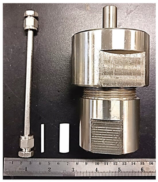
Figure 1.
Comparison of small tubular and conventional reactors and supports.
2. Materials and Methods
2.1. Materials
Colloidal silica (LUDOX® AS-40 colloidal silica, Assay: 40%, Sigma Aldrich, St. Louis, MO, USA), ultrastable Y-type zeolite particles (HSZ-390HUA, Tosoh Corp., Tokyo, Japan), N,N,N-trimethyl-1-adamantammonium hydroxide (TMAdaOH) (Assay: 25%, Sachem Inc., Austin, TX, USA), sodium hydroxide (Assay: 97%, FUJIFILM Wako Pure Chemical Industries, Osaka, Japan), sodium aluminate (FUJIFILM Wako Pure Chemical Industries, Osaka, Japan), aluminum hydroxide (FUJIFILM Wako Pure Chemical Industries, Osaka, Japan), ammonia solution (Assay: 28%, Nacalai Tesque, Inc., Kyoto, Japan), and nitric acid (Assay: 67%, Tokyo Chemical Industry Co., Ltd., Tokyo, Japan) were used without any pretreatment. Distilled and pure water were produced in-house. An α-alumina support (OD: 2.5 mm, ID: 2.0 mm, and average pore diameter: 150 nm) was used.
2.2. Synthesis of CHA Seed Crystal
The CHA seed crystal was synthesized using sodium aluminate, sodium hydroxide, TMAdaOH solution, and ultrastable Y-type zeolite particles according to the literature [16]. The molar composition of the synthesis solution was 1 SiO2: 0.025 Al2O3: 0.1 Na2O: 0.2 TMAdaOH: 20 H2O. After stirring for 1 h at ambient temperature, the mixture was poured into a PTFE-lined stainless-steel autoclave, and a hydrothermal reaction was carried out at 160 °C for three days; the product was then recovered by filtration, washed with distilled water, and dried at 80 °C overnight. Then, the product was calcined at 450 °C for 10 h with heating and cooling rates of 0.3 °C/min.
2.3. Synthesis of CHA Membrane
CHA seed crystals were deposited onto an α-alumina capillary support via dip-coating, with the support being pulled up from the seed crystal solution at a rate of 5 mm/min. The seeded supports were then dried at room temperature (R.T.), 200 °C overnight, or calcined at 450 °C for 24 h. The synthesis solution was prepared using a molar composition of 1 SiO2: 0.01 Al2O3: 0.01 Na2O: 0.6 TMAdaOH: 44 H2O [35]; details of the procedure are provided in Figure S1 of the Supplementary Materials. The seeded support was placed in the small tubular reactor, which was filled with a precursor solution of approximately 70% of the reactor volume, and hydrothermal synthesis was performed for 10 min to 24 h in an oil bath at 160 °C. Once the reactor had recovered from the oil bath and cooled to room temperature after 5 min, the membrane was washed with distilled water several times and dried overnight at room temperature. The CHA membrane was obtained via calcination at 450 °C for 24 h with a heating and cooling rate of 0.3 °C/min.
2.4. Characterization
X-ray diffraction patterns were collected using an X-ray diffractometer (XRD D8 ADVANCE, Bruker, Billerica, MA, USA), X-ray tube Cu (1.54060 Å) with a voltage of 40.0 kV, current of 40.0 mA, measurement range of 5 to 80 degrees, step width of 0.02 degrees, measurement time of 160 s, incident angle of 0.3 degrees, slit width of 8 mm, and light receiving width of 3 mm. The XRD patterns were compared to standard patterns from the International Zeolite Association database [49]. The appearance of seed crystals and a membrane was observed using a high-resolution field emission scanning electron microscope (Hitachi High-Technologies, S-4800, Tokyo, Japan) at 5 kV. In addition, the elemental composition of the membrane was determined using energy-dispersive X-ray spectroscopy (EDX, Oxford Instruments, Abingdon, Oxfordshire, UK) at 20 kV. The chemical composition of the prepared seed crystal was analyzed using wavelength-dispersive X-ray fluorescence analysis (XRF S8 TIGER, Bruker, Billerica, MA, USA). The zeta potential of the prepared seed crystal solution was measured using a Zetasizer (Malvern Panalytical, Malvern, Worcestershire, UK) to evaluate surface charge characteristics.
2.5. Pervaporation Test
The membrane performance was evaluated via pervaporation (PV) tests using a 90 wt% 2-propanol (2-PrOH) aqueous solution at 50 °C and a pervaporation device. The vaporized permeate was collected in a cooling trap placed in liquid nitrogen, and its weight was measured for the calculation of total flux. Thereafter, the compositions of the feed and permeate were analyzed using a gas chromatograph equipped with a TCD (Shimadzu Co., Kyoto, Japan, GC-8A) and a Porapack Q column.
The total permeation flux J [kg m−2 h−1] and separation factor αH2O/2-PrOH were calculated using Equations (1) and (2).
In Equation (1), W, A, and t in are the weight of permeate collected, the effective membrane area, and the time interval for permeated sample collection, respectively. In Equation (2), X and Y are the weight fractions of the species in the feed and permeate, respectively [50,51].
3. Results and Discussion
3.1. Effect of Dip-Coating Solution
The methods employed to attach zeolite seeds onto porous support for secondary growth involve the use of either covalent linkage or electrostatic forces, pH effects, cationic polymers, or silane coupling agents [52]. Here, the effects of pH on the coating of the alumina support with ca. 1 µm of CHA seed crystal were investigated. The XRD pattern and appearance of the seed crystal used in this study are shown in Figures S2 and S3, which are available in the Supplementary Materials. The SEM images of the seeded supports shown in Figure S4 depict the effects of the pH of the seed solutions. The pH of the solution was adjusted using aqueous ammonia solution, and seeded supports were calcined at 450 °C.
The CHA membranes were synthesized using seeded supports prepared with different pH seed solutions, as confirmed by Figure 2 and Figure S5 (Supplementary Materials). SEM images of the membrane surface and cross-section reveal successful secondary growth during hydrothermal synthesis inside the small tubular reactor. After 60 min of synthesis, the membrane thicknesses were 0.51 μm for 1 wt%-pH 7 and 0.59 μm for 1 wt%-pH 8, indicating the negligible effect of pH on the membrane thickness. In contrast, the SEM images (Figure 2a and Figure S5a) show that the membrane synthesized without seeds for 60 min formed a thinner and incomplete zeolite layer. This clearly shows that seed crystals are essential to the synthesis of a membrane in a very short time.
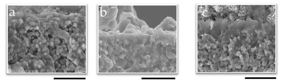
Figure 2.
SEM image of the cross-section of membranes synthesized in 60 min with (a) no seed, (b) 1 wt%-pH 7, and (c) 1 wt%-pH 8; the scale bar represents 2 µm.
As shown in Figure 3, PV tests with 90 wt% 2-propanol revealed that membranes seeded with 1 wt%-pH 8 demonstrated a high αH2O/2-PrOH of 1018, even at 50 min. In contrast, the membranes seeded with 1 wt%-pH 7 required a longer period of synthesis to match the performance of those seeded at pH 8. For instance, αH2O/2-PrOH was 131 at 60 min, which was much lower than that with 1 wt%-pH 8; finally, comparable selectivity was achieved when using the membrane with pH 8 at 80 min. The SEM images (Figure S4) show the slightly low uniformity of seed crystal distribution at pH 7. To further illustrate the advantage of seeding, we also tested in situ synthesis using unseeded supports. Among the three membranes synthesized without seeding, only the 50 min sample showed selectivity, but that was rather low (αH2O/2-PrOH = 105). This clearly indicates the low performance and poor reproducibility of the membranes synthesized without seeding.
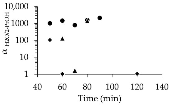
Figure 3.
Relationship between separation factor and time for membrane with no seed (◆), dip-coated using 1 wt%-pH 7 (▲), and dip-coated using 1 wt%-pH 8 (●).
Our findings aligned with a previous report by Hu et al. [53], who found that the pH of the seed solution influenced the distribution of seed crystals on the support. They observed that at pH 2.2 and pH 9.3, electrostatic repulsion between the seed and the support led to lower seed coverage compared to pH 7, particularly in the case of silicalite-1 and the alumina support. In this study of CHA membranes using an alumina support, it seems that using a coating solution of pH 8 resulted in better performance.
The zeta potential measurements of 1 wt% seed suspensions (pH 4–10) ranged from −35.1 to −61.3 mV, aligning with previous observations [54]. α-Alumina exhibited a neutral charge at a pH around 8 [55]. At pH 8, the negatively charged seeds interact favorably with the mildly charged alumina, enhancing attachment and improving reproducibility compared to pH 7.
In situ synthesis is known to require extended durations due to the induction period necessary for zeolite nucleation [56]. In the absence of seeding, nucleation occurs either on the support surface (heterogeneous nucleation) [56,57,58] or within the synthesis solution, followed by adsorption onto the support (homogeneous nucleation) [58,59]. Seeding eliminates this nucleation phase, enabling faster and more consistent membrane formation. The successful formation of the 50 min membrane suggests that seeded membranes may be synthesized in even shorter times.
Variations in membrane quality may be attributed to differences in the physicochemical properties of the support material, which are known to influence nucleation [60]. Although the condition of the support’s surface was not a variable controlled in this study, differences in surface quality likely contributed to the inconsistent performance observed. The formation of zeolite membranes involves two distinct stages: nucleation and crystal growth. The secondary growth method, which involves pre-seeding the support prior to hydrothermal treatment, offers improved control over these processes [56]. This approach reduces the nucleation induction period and minimizes the influence of support surface chemistry, leading to enhanced reproducibility and membrane quality [56,60]. These findings are consistent with the superior performance and consistency observed for membranes prepared using the seeded method.
To improve the distribution of seed crystals, the effect of the seed concentration in the solution was investigated at pH 8. Figure S6 shows the surface appearance of the seeded support with different seed concentrations in the seeded solution. Increasing the seed concentration from 0.1 wt% (Figure S6a) to 1 wt% (Figure S4b) enhanced crystal coverage, promoted uniform seed distribution, and minimized void areas on the support. However, concentrations above 1 wt% led to noticeable crystal aggregation. At 2 wt% and 4 wt%, the support was fully covered, but excessive clustering compromised uniformity. Therefore, while higher seed concentrations improve the density of seed crystals, they also increase the risk of aggregation.
SEM images of the membrane cross-section (Figure S7) and surface (Figure S8) confirm successful secondary growth after 70 min of hydrothermal synthesis within the small tubular reactor. The membrane thickness remained consistent at approximately 0.5 μm across all samples. However, morphological differences were observed, primarily in the shape of the crystals and surface uniformity. As shown in Figure S8c, membranes synthesized for 70 min using a 4 wt% solution exhibited regions with an additional layer of aggregated zeolite crystals, suggesting an uneven seed distribution. This localized over-seeding likely led to thicker or multi-layered CHA membrane formation. The 2 wt% membrane showed fewer additional layers but still displayed areas with an uneven thickness. In contrast, the 0.1 wt% membrane exhibited less defined crystal edges on the surface, indicating a lower degree of membrane maturity compared to the other two.
The comparison of the performance of the membranes prepared with different seed concentrations is summarized in Figure 4. As already mentioned, at 1 wt%-pH 8, excellent separation was achieved even at 50 min (αH2O/2-PrOH = 1018), and high selectivity was reproducibly obtained when the synthesis time was above 50 min. In contrast, at 0.1 wt%-pH 8, most membranes underperformed, except the 90 min sample (αH2O/2-PrOH = 975). Increasing the seed concentration to 2 wt% and 4 wt% yielded a high performance (e.g., αH2O/2-PrOH = 1625 at 70 min for 4 wt%), but the performance dropped or became inconsistent at longer synthesis times.
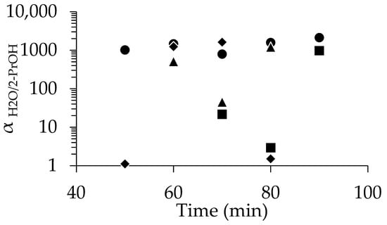
Figure 4.
Relationship between separation factor and time for membranes dip-coated using pH 8 solutions at concentrations of 0.1% (■), 1% (●), 2% (▲) and 4% (◆).
Wong et al. studied the morphology of the zeolite membrane and reported that poor intergrowth leads to defects and cracks, reducing selectivity [56]. The aggregation of zeolite seed crystals in certain areas promotes poor intergrowth, leading to a degraded membrane layer and reduced performance. The size and morphology of crystal seeds impact intercrystalline porosity and crystal intergrowth, while grain boundaries and defects create non-zeolite transport pathways [56]. This may explain the inconsistent performance of membranes, especially those with higher seed concentrations. Optimizing the size and homogeneity of seed crystals, an area not explored in this study, could be a key focus of future research.
In the case of CHA zeolite on alumina support, 1 wt%-pH 8 seeding conditions consistently yielded optimal results, owing to its better distribution. For the rapid synthesis of zeolite membranes, achieving smooth and uniform seed coverage with minimal intercrystalline voids is crucial for minimizing the time required for synthesis.
3.2. Effect of Drying Condition for Seeded Support
Figure S9 shows the SEM images of the surface of the dip-coated seeded support prepared using a 1 wt%-pH 8 seed solution with a different post-treatment. The seeded support exhibited a well-distributed coating of seed crystals, and the drying conditions had no apparent impact.
The cross-section and the surface of the SEM images of the membranes synthesized for 60 min are shown in Figure 5 and Figure S10 in the Supplementary Materials, respectively. The calcined membrane synthesized for 60 min, shown in Figure 5c, has a thickness of around 0.5 µm, which was the same for the other two membranes synthesized using different drying conditions for the seeded support (Figure 5a,b). However, reproducibility issues were observed when the seeded support was dried at room temperature, as shown in Figure 6. The membrane synthesized for 50 min exhibited even lower separation (αH2O/2-PrOH = 9.71). However, the min membranes synthesized for 60 min and 120 demonstrated excellent separation factors, exceeding 1000. The membrane synthesized for 50 min and prepared using a seeded support dried at 200 °C exhibited good separation performance (αH2O/2-PrOH = 288); the membrane synthesized for 60 min also showed good performance (αH2O/2-PrOH = 341), which is promising. On the other hand, not only did the membrane synthesized for 120 min show poor performance, the overall results indicate that the membranes synthesized using the seeded supports calcined at 450 °C performed better. Additionally, they demonstrated improved reproducibility, as all three membranes exhibited good separation αH2O/2-PrOH (1018, 1466, and 1009 for 50 min, 60 min, and 120 min, respectively).
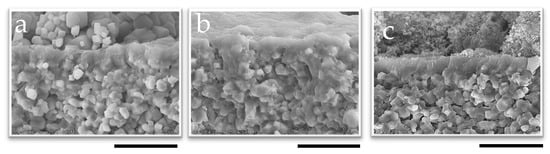
Figure 5.
SEM image of the membrane cross-section synthesized for 60 min using 1 wt%-pH 8 seed solution dried at (a) R.T., (b) 200 °C, and (c) calcined at 450 °C; the scale bar represents 2 µm.
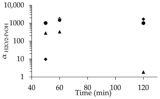
Figure 6.
Relationship between separation factor and time for the membrane dip-coated using 1 wt%-pH 8, dried at R.T. (◆), 200 °C (▲), and calcined at 450 °C (●).
The different treatments of the seeded support resulted in a difference in the quality of the membranes. Another study reported that drying at 80 °C after rub-coating for 4 h improved the binding strength between the seed crystal and support [43]. While rub-coating facilitates some bond formation between the seed crystals and the support surface during the rubbing process, dip-coating lacks this advantage. Therefore, dip-coated membranes require additional post-treatment to ensure that the seed crystals remain on the support’s surface. This issue has been previously reported using various approaches. For example, some studies have stated that dip-coating is widely used as a secondary synthesis method, but it has certain limitations. The primary drawback is that seed crystals do not firmly adhere to or closely attach to the support surface, and they can easily detach when the support is withdrawn [61,62]. Previous studies have reported several challenges in secondary growth, including uneven seed coating, coating detachment, and seed damage, which can affect germination rates and growth vigor during synthesis [63,64]. To address these issues, particularly coating detachment, we calcined seeded supports prior to hydrothermal synthesis; in this study, lower temperatures such as 200 °C were used for sufficient water removal, while higher temperatures such as 450 °C aimed to induce the formation of chemical bonds. Heating by drying overnight at 200 °C was first attempted, emulating the 80 °C procedure reported elsewhere [43]; however, this proved insufficient. Calcination at 450 °C exhibited better separation performance, ensuring seed crystals remained attached and improving the quality of the dip-coated support. While this approach improved the quality of membranes, the calcination of the seeded support reduces the overall productivity of zeolite membranes; therefore, a more efficient seeding method must be developed.
3.3. Effect of Hydrothermal Synthesis Time
Here, the effect of synthesis time was investigated. Figure 7 and Figure S11 in the Supplementary Materials show the XRD patterns of CHA membranes synthesized for different durations using 1 wt%-pH 8 seeded supports calcined at 450 °C. A broad peak observed between 20° and 25°, representing the amorphous phase, was derived from the support itself. As shown in Figure 7, peaks of (101) and (211) of CHA were observed at 9.1° and 20.8°, respectively, even after 20 min of synthesis. The characteristic peaks were detectable, although their intensities were very low. This can be attributed to the extremely small membrane size and/or the thinness of the membrane, both of which limit the overall detection sensitivity. A comparison between the XRD patterns of the seeded support in the Supplementary Materials and the 20 min membrane confirmed the secondary growth of CHA on the seeded support. Furthermore, these peak intensities for CHA did not increase with synthesis time, indicating that less secondary growth of CHA was observed after 20 min of synthesis, as can be seen in Figure 7.
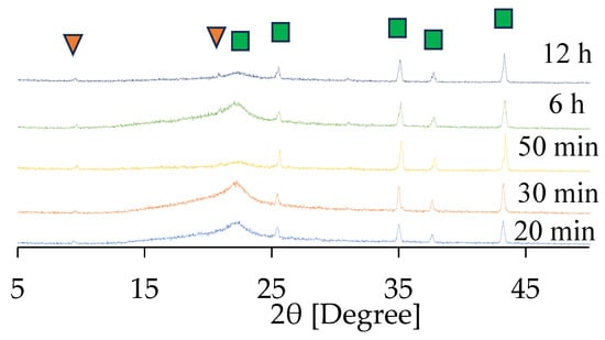
Figure 7.
XRD patterns of the CHA membrane prepared using 1.0 wt% pH 8 dip-coating. Characteristic peaks of CHA (▼) and α-alumina (■) are indicated by respective markers.
The appearance of CHA membranes at different synthesis times is shown in Figure 8 and Figure 9, as well as in Figures S12 and S13. A dense layer with a thickness of 0.6 μm was successfully formed within 10 min of synthesis, as confirmed in Figure 8 and Figure S12; no significant increase in membrane thickness was observed despite an increase in the length of synthesis, even after 12 h of synthesis. The thinness of the membrane and the fact that there was no further increase in the membrane thickness with the synthesis duration showed good agreement with the results of the XRD patterns, as shown in Figure 7. Additionally, it is possible that the membrane thickness did not increase further because there was a limited amount of raw materials available in the synthesis solution relative to the surface area of the capillary support due to the very small inner volume of the reactor (1.70 cm3). Indeed, by using the same molar composition of synthesis solutions used in this study, CHA membranes synthesized in a conventional autoclave could grow from 0.5 μm to 1.4 μm [37].
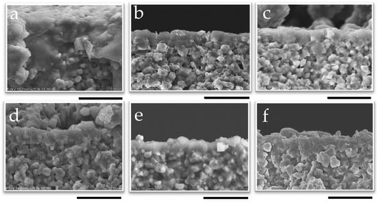
Figure 8.
SEM image of the cross-section of membranes synthesized at 1 wt% pH 8 for (a) 10 min, (b) 30 min, (c) 50 min, (d) 2 h, (e) 6 h, and (f) 12 h; the scale bar represents 2 µm.
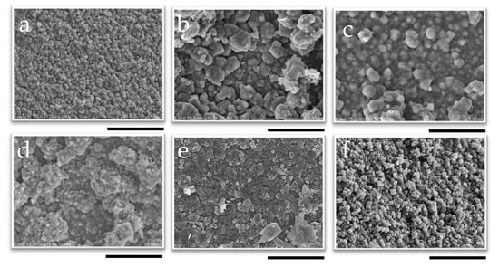
Figure 9.
SEM image of the surface of membranes synthesized at 1 wt% pH 8 for (a) 10 min, (b) 30 min, (c) 50 min, (d) 2 h, (e) 6 h, and (f) 12 h; the scale bar represents 5 µm.
While no further growth was observed in the cross-sectional images, the SEM surface images in Figure 9 clearly show the influence of synthesis time on the morphology of the membrane. The cubic structure of the CHA crystals became more pronounced as the synthesis time increased, indicating that the crystals were growing and developing more distinct shapes as the duration of synthesis increased. This indicates that the recrystallization of the developed CHA membrane was proceeding during hydrothermal synthesis. This aligns with previous reports indicating that the morphology and crystal size of CHA zeolite membranes depend on the temperature and crystallization time [65]. One such study reported that, at different synthesis times, block-shaped crystals increased in size from 1–5 µm at 12 h to 4–6 µm at 16 and 20 h. At the same temperature, these block-shaped crystals transitioned into column-shaped MER zeolite crystals as the synthesis time increased to 16 h. The same phenomenon was also reported by Hasegawa et al.; in their study, an increase in the duration of membrane synthesis led to the development of block-shaped crystals [42].
Figure 10 presents the dependence of the PV performance of CHA membranes on the synthesis time. The membrane synthesized for 30 min showed αH2O/2-PrOH of 940 and a total flux of 1.98 kg/(m2 h). The maximum αH2O/2-PrOH of 2322 was obtained at 45 min of synthesis; meanwhile, at 20 min, the membrane did not show selectivity. This is in line with the SEM image showing that the CHA membrane sufficiently grew to a thickness of 0.65 µm even at 30 min, indicating that the small tubular reactor enables an extreme reduction in the hydrothermal synthesis time. Starting from 30 min of synthesis, most of the membranes exhibited a αH2O/2-PrOH greater than 1000, and the total flux dropped sharply to 2–3 kg/(m2 h) in the first 30 min. The rapid improvement in separation performance and reduction in total flux in the first 30 min can be primarily attributed to the reduction in membrane defects. For instance, a membrane was formed after 10 min of synthesis, as confirmed in Figure 8. However, this membrane had many defects, resulting in no selectivity and high flux, as shown in Figure 10. Interestingly, Figure S14 demonstrates a clear relationship between the synthesis time and both the separation factor and total flux, with a noticeable difference observed before and after the 30 min mark; however, some data points deviate from the overall trend. As shown in Figure 8, the growth of the membrane, in terms of thickness, was completed in the first few tens of minutes when most of the Si and Al sources in the synthesis solution had been consumed. Then, a number of membrane defects were fixed in this period, with a further extension of the synthesis time potentially not repairing the defects, despite the edges of the crystal grain developing. As can be seen in Figure S14a, an increase in synthesis time does not necessarily result in a decrease in total flux, and Figure S14b indicates that a longer synthesis time correlates with a constant increase in separation factors.
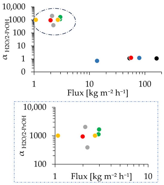
Figure 10.
PV performance of the CHA membrane prepared with 1.0 wt% pH 8 dip-coating, with synthesis times of 10 min (black), 20 min (blue), 30 min (red), 40 min (green), 2 h (yellow), and 12 h (gray). The dotted box in the upper image indicates the area shown in the magnified image below.
The separation of H2O/2-PrOH through the CHA membrane occurs mainly due to their size difference (molecular sieving). The kinetic diameter of isopropanol molecules is 0.47 nm [66,67], while water molecules are smaller at 0.28 nm [68]. Since the CHA-type zeolite has a pore size of 0.38 nm [66], it is too small for most isopropanol molecules but allows water molecules to pass through easily, while isopropanol is inhibited. As a result, the membrane effectively blocks isopropanol while letting water permeate freely, leading to a high separation factor in the PV test of the H2O/2-PrOH mixture [67]. Figure 10 and Figure S14 showed relatively scattered values for the total flux and separation factor, which could be due to the existence of a composite layer of zeolite and support in some of the zeolite membranes. It was found that Si can be detected inside the alumina support shown in Figure S15. A membrane with more areas containing a composite layer underneath may influence the overall performance of that membrane. The formation of composite layers can be due to the condition of the support’s surface and pores, in addition to the distribution of seed crystals on the surface of the membrane and inside the membrane’s pores. To clarify the impact of this composite layer on the membrane performance and improve the reproducibility, further investigations are underway and will be reported in the near future.
We can conclude that the hydrothermal synthesis time at which the membrane shows good selectivity can be shortened to 30 min under the synthesis conditions investigated in this study. However, some membranes exhibited a low αH2O/2-PrOH of less than 500, even with synthesis times longer than 30 min; this suggests that these exceptions are likely independent of synthesis time. As mentioned, extending the synthesis time did not contribute to an improvement in membrane performance, likely due to the lack of additional sources for membrane growth. The presence of large inter-crystal voids between the seed crystals negatively impacted the membrane’s compactness, as already mentioned. Consequently, a further reduction in synthesis time and improvements in reproducibility can be achieved by enhancing the quality of the seed layer.
Table 4 compares the PV performance of CHA membranes. Sato et al. [69] suggested that a performance of αH2O/2-PrOH 1600 can be sufficient for practical applications. Our membrane demonstrated comparable or even higher separation factors compared to most reported results, confirming that this study excels in terms of synthesis time. Further research is needed to gather more data for industrial applications. However, this study demonstrates that a small tubular reactor can effectively and rapidly synthesize CHA membranes.
Table 4.
Comparison of the pervaporation test results of H2O/2-PrOH.
In summary, the CHA membrane was successfully synthesized rapidly using a small tubular reactor in an oil bath. Even at 30 min, the membrane reached a thickness of 0.65 µm and exhibited good separation performance. Extending the synthesis time to 40 min improved reproducibility and reduced defects, as seen in the decline in total flux. However, further extension did not have an apparent effect on the membrane performance and membrane thickness due to the small size of the tubular reactor. Compared to the literature, this small tubular reactor remarkably shortened the synthesis time while maintaining a competitive separation performance, highlighting its potential for industrial applications.
Our method enables the rapid synthesis of zeolite membranes, potentially leading to a reduction in production costs. This result indicates that efficient thermal management can play a critical role in shortening synthesis times. Moreover, the use of an oil bath is beneficial considering its practical application; this approach is scalable, representing a viable alternative to conventional methods. To our knowledge, the synthesis time reported in this study represents one of the fastest reported for zeolite membranes. Further reductions in synthesis time may be achievable by optimizing the seeded support to produce a smoother surface with more uniformly distributed seed crystals, thereby enhancing the efficiency of crystal nucleation and growth.
On the other hand, issues related to the low-cost synthesis of seed crystals, the seeding procedure, including the drying period, post-treatment after hydrothermal synthesis and the usage of OSDA remain to be overcome. The OSDA-free synthesis of zeolite membranes has been reported [66,70] and may represent a promising avenue for future optimization. The continuous-flow synthesis of zeolite crystals [29] may be integrated into our membrane production method to further improve productivity. The seeding method and post-treatment also have a significant impact on membrane productivity, and the scaling-up and usage of conventional supports are mandatory for practical application. These issues will be investigated in the future.
In addition to dimensional control, we recognize that further advances will require tailored reactor architectures that are capable of combining efficient heat transfer with robust membrane support. Our next research will address the versatility of this approach across different zeolite types, as well as strategies for scaling up and implementing conventional-sized supports by working on novel design reactors. Together, these efforts will help establish scalable and versatile pathways for ultrafast zeolite membrane production, reinforcing the potential application of enhanced heat transfer as a platform technology for next-generation membrane synthesis.
4. Conclusions
The CHA membrane was successfully synthesized rapidly using a small tubular reactor in an oil bath. Even at 30 min, the membrane reached a thickness of 0.65 µm and exhibited good separation performance. Dip-coating with 1 wt% seed crystals at pH 8 ensured good distribution with minimal aggregation. While increasing the seed concentration improved distribution, avoiding aggregation was crucial. The calcination of the seeded support improved the performance and reproducibility of the membrane under the synthesis conditions. Extending the synthesis duration to 40 min improved reproducibility and reduced defects, as seen in the decline in total flux. However, a further extension of the synthesis duration did not have an apparent effect on the membrane performance and membrane thickness due to the small size of the tubular reactor. Compared to the literature, this small tubular reactor remarkably shortened the synthesis time while maintaining competitive separation performance. This highlighted that heat transfer played an important role in significantly reducing synthesis time. Key challenges remain in seed synthesis, seeding steps, membrane post-treatment, and OSDA use. OSDA-free and continuous-flow synthesis could be promising, with future work focusing on their productivity and practical application. As improvements are made to the pre- and post-synthesis processes, the significance of reducing hydrothermal synthesis time will become increasingly important for achieving more efficient and cost-effective zeolite membrane production. Our ongoing work focuses on exploring the versatility of this approach across different zeolite types and developing strategies for scale-up using conventional-sized supports. These efforts aim to establish scalable and broadly applicable pathways for the rapid and efficient production of zeolite membranes.
Supplementary Materials
The following supporting information can be downloaded at https://www.mdpi.com/article/10.3390/suschem6040039/s1. Figure S1. CHA membrane synthesis procedure; Figure S2. XRD pattern of CHA seed crystal compared to the standard from IZA; Figure S3. SEM image of CHA seed crystal, the scale bar represents (a) 2 µm and (b) 10 µm; Figure S4. SEM images of seeded supports coated with solution 1 wt% of (a) pH 7 and (b) pH 8, (scale bar: 10 µm); Figure S5. SEM image of the surface of membranes of 60 min (a) no seed, (b) 1 wt%-pH 7, and (c) 1 wt%-pH 8, the scale bar represents 5 µm; Figure S6. SEM image of the surface of seeded support coating using coating solutions at pH 8 with (a) 0.1 wt%, (b) 2 wt%, and (c) 4 wt% of seed crystal. Scale bar: 20 µm; Figure S7. SEM images of the cross section of membranes synthesized for 70 min using coating solutions at pH 8 with (a) 0.1 wt%, (b) 2 wt%, and (c) 4 wt% of seed crystal. Scale bar: 2 µm; Figure S8. SEM images of the surface of membranes synthesized for 70 min using coating solutions at pH 8 with (a) 0.1 wt%, (b) 2 wt%, and (c) 4 wt% of seed crystal. Scale bar: 5 µm; Figure S9. SEM image of the surfaces of seeded supports using a 1 wt% pH 8 seed solution dried at (a) R.T., (b) 200 °C, and (c) calcined at 450 °C, the scale bar represents 10 µm; Figure S10. SEM image of the membrane surfaces synthesized for 60 min using 1 wt%-pH 8 seed solution dried at (a) R.T., (b) 200 °C, and (c) calcined at 450 °C, the scale bar represents 2 µm. Figure S11. XRD patterns of seeded support and CHA membrane of 20 min; Figure S12. SEM image of the cross-section of membranes of 1 wt% pH 8, a 15 min, b 20 min, c 40 min, d 45 min, e 60 min, f 70 min, g 80 min, h 90 min, i 4 h, j 24 h, the scale bar represents 2 µm, Figure S13. SEM image of the surface of membranes of 1 wt% pH 8, a 15 min, b 20 min, c 40 min, d 45 min, e 60 min, f 70 min, g 80 min, h 90 min, i 4 h, j 24 h, the scale bar represents 5 µm; Figure S14. (a) Relation of total flux vs synthesis time, (b) Relation of separation factor vs synthesis time of the CHA membrane prepared with 1.0 wt% pH 8 dip-coating; Figure S15. EDX-SEM cross-sectional analysis of membranes prepared of 1 wt% pH 8 for (a) 40 min and (b) 120 min. For each condition: (1) SEM micrograph, (2) elemental mapping of Si (red), and (3) combined elemental mapping of Si (red) and Al (green). The scale bar represents (a) 2.5 µm and (b) 5 µm.
Author Contributions
Conceptualization, M.M.; methodology, M.M.; validation, S.U. and Y.O.; formal analysis, R.J.; investigation, R.J., Y.H. and Y.O.; resources, M.M. and Y.H.; data curation, M.M.; writing—original draft preparation, R.J.; writing—review and editing, M.M. and Y.H.; visualization, R.J. and M.M.; supervision, M.M.; project administration, M.M.; funding acquisition, M.M. All authors have read and agreed to the published version of the manuscript.
Funding
This research was financially supported by JSPS KAKENHI GRANT Number 22K04801.
Institutional Review Board Statement
Not applicable.
Informed Consent Statement
Not applicable.
Data Availability Statement
The original contributions presented in the study are included in the article; further inquiries can be directed to the corresponding author.
Conflicts of Interest
The authors declare that they have no known competing financial interests or personal relationships that could have appeared to have influenced the work reported in this paper.
Abbreviations
The following abbreviations are used in this manuscript:
| TMAdaOH | N,N,N-trimethyl-1-adamantammonium hydroxide |
| PTFE | Polytetrafluoroethylene |
| SEM | Scanning Electron Microscope |
| XRD | X-Ray Diffraction |
| XRF | X-Ray Fluorescence |
| EDX | Energy-Dispersive X-ray |
| GC | Gas Chromatography |
| TCD | Thermal Conductivity Detector |
| IPA | Isopropanol |
References
- Zimmermann, N.E.R.; Haranczyk, M. History and Utility of Zeolite Framework-Type Discovery from a Data-Science Perspective. Cryst. Growth Des. 2016, 16, 3043–3048. [Google Scholar] [CrossRef]
- Yang, W.; Li, Y. Zeolite Membranes. In Inorganic Membranes for Energy and Environmental Applications; Springer: New York, NY, USA, 2009; pp. 275–286. [Google Scholar] [CrossRef]
- Raganati, F.; Procentese, A.; Olivieri, G.; Russo, M.E.; Salatino, P.; Marzocchella, A. Bio-Butanol Separation by Adsorption on Various Materials: Assessment of Isotherms and Effects of Other ABE-Fermentation Compounds. Sep. Purif. Technol. 2018, 191, 328–339. [Google Scholar] [CrossRef]
- Miyamoto, M.; Iwatsuka, H.; Oumi, Y.; Uemiya, S.; Van Den Perre, S.; Baron, G.V.; Denayer, J.F.M. Effect of Core-Shell Structuring of Chabazite Zeolite with a Siliceous Zeolite Thin Layer on the Separation of Acetone-Butanol-Ethanol Vapor in Humid Vapor Conditions. Chem. Eng. J. 2019, 363, 292–299. [Google Scholar] [CrossRef]
- Daems, I.; Singh, R.; Baron, G.; Denayer, J. Length Exclusion in the Adsorption of Chain Molecules on Chabazite Type Zeolites. Chem. Commun. 2007, 13, 1316–1318. [Google Scholar] [CrossRef] [PubMed]
- Aziz, M.T.; Naqvi, S.A.R.; Janjua, M.R.S.A.; Alam, M.; Gill, W.A. Exploring the Adsorption Behavior of Molecular Hydrogen on CHA-Zeolite by Comparing the Performance of Various Force Field Methods. RSC Adv. 2023, 13, 30937–30950. [Google Scholar] [CrossRef]
- Ghojavand, S.; Clatworthy, E.B.; Coasne, B.; Piva, D.H.; Guillet-Nicolas, R.; Medeiris-Costa, I.C.; Desmurs, M.; Ruaux, V.; Pugnet, V.; Kumar-Gandhi, P.; et al. Dynamic CO2 Separation Performance of Nano-Sized CHA Zeolites under Multi-Component Gas Mixtures. Chem. Eng. J. 2024, 500, 157101. [Google Scholar] [CrossRef]
- Li, S.; Tuan, V.A.; Falconer, J.L.; Noble, R.D. X-Type Zeolite Membranes: Preparation, Characterization, and Pervaporation Performance. Microporous Mesoporous Mater. 2002, 53, 59–70. [Google Scholar] [CrossRef]
- Suzuki, H. Compound Film Having Surface Layer of Thin Film of Cage Zeolite and Preparation Thereof. JP58135155A, 26 July 1983. [Google Scholar]
- Morigami, Y.; Kondo, M.; Abe, J.; Kita, H.; Okamoto, K. The First Large-Scale Pervaporation Plant Using Tubular-Type Module with Zeolite NaA Membrane. Sep. Purif. Technol. 2001, 25, 251–260. [Google Scholar] [CrossRef]
- Sinaei Nobandegani, M.; Yu, L.; Hedlund, J. Zeolite Membrane Process for Industrial CO2/CH4 Separation. Chem. Eng. J. 2022, 446, 137223. [Google Scholar] [CrossRef]
- Galizia, M.; Chi, W.S.; Smith, Z.P.; Merkel, T.C.; Baker, R.W.; Freeman, B.D. 50th Anniversary Perspective: Polymers and Mixed Matrix Membranes for Gas and Vapor Separation: A Review and Prospective Opportunities. Macromolecules 2017, 50, 7809–7843. [Google Scholar] [CrossRef]
- Hamid, M.R.A.; Jeong, H.K. Recent Advances on Mixed-Matrix Membranes for Gas Separation: Opportunities and Engineering Challenges. Korean J. Chem. Eng. 2018, 35, 1577–1600. [Google Scholar] [CrossRef]
- Nandi, B.K.; Uppaluri, R.; Purkait, M.K. Preparation and Characterization of Low Cost Ceramic Membranes for Micro-Filtration Applications. Appl. Clay Sci. 2008, 42, 102–110. [Google Scholar] [CrossRef]
- Yu, L.; Hedlund, J. Large and Highly Selective and Permeable CHA Zeolite Membranes. Ind. Eng. Chem. Res. 2023, 62, 16058–16069. [Google Scholar] [CrossRef]
- Hasegawa, Y.; Abe, C.; Ikeda, A. Pervaporative Dehydration of Organic Solvents Using High-Silica CHA-Type Zeolite Membrane. Membranes 2021, 11, 229. [Google Scholar] [CrossRef] [PubMed]
- Osman, A.I.; Chen, Z.; Elgarahy, A.M.; Farghali, M.; Mohamed, I.M.A.; Priya, A.K.; Hawash, H.B.; Yap, P.S. Membrane Technology for Energy Saving: Principles, Techniques, Applications, Challenges, and Prospects. Adv. Energy Sustain. Res. 2024, 5, 2400011. [Google Scholar] [CrossRef]
- Liang, B.; He, X.; Hou, J.; Li, L.; Tang, Z. Membrane Separation in Organic Liquid: Technologies, Achievements, and Opportunities. Adv. Mater. 2019, 31, 1806090. [Google Scholar] [CrossRef]
- Kapteijn, F.; Wang, X. Zeolite Membranes—The Importance of Support Analysis. Chem. Ing. Tech. 2022, 94, 23–30. [Google Scholar] [CrossRef]
- Caro, J.; Noack, M. Zeolite Membranes—Recent Developments and Progress. Microporous Mesoporous Mater. 2008, 115, 215–233. [Google Scholar] [CrossRef]
- Meindersma, G.W.; De Haan, A.B. Economical Feasibility of Zeolite Membranes for Industrial Scale Separations of Aromatic Hydrocarbons. Desalination 2002, 149, 29–34. [Google Scholar] [CrossRef]
- Kooijman, H.A.; Sorensen, E. Recent Advances and Future Perspectives on More Sustainable and Energy Efficient Distillation Processes. Chem. Eng. Res. Des. 2022, 188, 473–482. [Google Scholar] [CrossRef]
- Zhang, H.; Chen, Y.; Cheng, H.; Wang, Y.; Cui, P.; Zheng, S.; Zhu, Z.; Wang, Y.; Lu, Y.; Gao, J. Comprehensive Analysis on the Economy and Energy Demand of Pressure-Swing Distillation and Pervaporation for Separating Waste Liquid Containing Multiple Components. Chin. J. Chem. Eng. 2023, 63, 12–20. [Google Scholar] [CrossRef]
- Sholl, D.S.; Lively, R.P. Seven Chemical Separations to Change the World. Nature 2016, 532, 435–437. [Google Scholar] [CrossRef] [PubMed]
- Gascon, J.; Kapteijn, F.; Zornoza, B.; Sebastián, V.; Casado, C.; Coronas, J. Practical Approach to Zeolitic Membranes and Coatings: State of the Art, Opportunities, Barriers, and Future Perspectives. Chem. Mater. 2012, 24, 2829–2844. [Google Scholar] [CrossRef]
- McLeary, E.E.; Jansen, J.C.; Kapteijn, F. Zeolite Based Films, Membranes and Membrane Reactors: Progress and Prospects. Microporous Mesoporous Mater. 2006, 90, 198–220. [Google Scholar] [CrossRef]
- Liu, N.; Zhang, H.; Ma, Y.; Li, Y.; Gui, T.; Zhu, M.; Wu, X.; Hu, N.; Chen, X. An Unexpected Accelerated-Fabrication of High-Flux CHA-Type Zeolite Membranes Enabled by Creating Silanol Nests in Their Seeds. J. Environ. Chem. Eng. 2025, 13, 115263. [Google Scholar] [CrossRef]
- Oh, Y.J.; Kang, S.K.; Lee, A.H.; Park, S.; Kim, S.; Choi, J.; Lee, P.S. Microstructural Engineering of Zeolite Membranes through Composite Seed Layers. Microporous Mesoporous Mater. 2023, 356, 112590. [Google Scholar] [CrossRef]
- Liu, Z.; Wakihara, T.; Oshima, K.; Nishioka, D.; Hotta, Y.; Elangovan, S.P.; Yanaba, Y.; Yoshikawa, T.; Chaikittisilp, W.; Matsuo, T.; et al. Widening Synthesis Bottlenecks: Realization of Ultrafast and Continuous-Flow Synthesis of High-Silica Zeolite SSZ-13 for NOx Removal. Angew. Chem. Int. Ed. 2015, 54, 5683–5687. [Google Scholar] [CrossRef] [PubMed]
- Liu, Z.; Zhu, J.; Wakihara, T.; Okubo, T. Ultrafast Synthesis of Zeolites: Breakthrough, Progress and Perspective. Inorg. Chem. Front. 2019, 6, 14–31. [Google Scholar] [CrossRef]
- Bai, L.; Chang, N.; Li, M.; Wang, Y.; Nan, G.; Zhang, Y.; Hu, D.; Zeng, G.; Wei, W. Ultrafast Synthesis of Thin SAPO-34 Zeolite Membrane by Oil-Bath Heating. Microporous Mesoporous Mater. 2017, 241, 392–399. [Google Scholar] [CrossRef]
- De Oñate Martinez, J.; Falamaki, C.; Baerlocher, C.; McCusker, L.B. Synthesis of Large Single Crystals of the Large-Pore Aluminophosphate Molecular Sieve VPI-5. Microporous Mesoporous Mater. 1999, 28, 261–269. [Google Scholar] [CrossRef]
- Kuperman, A.; Nadimi, S.; Oliver, S.; Ozin, G.A.; Garcés, J.M.; Olken, M.M. Non-Aqueous Synthesis of Giant Crystals of Zeolites and Molecular Sieves. Nature 1993, 365, 239–242. [Google Scholar] [CrossRef]
- Tang, H.; Bai, L.; Wang, M.; Zhang, Y.; Li, M.; Wang, M.; Kong, L.; Xu, N.; Zhang, Y.; Rao, P. Fast Synthesis of Thin High Silica SSZ-13 Zeolite Membrane Using Oil-Bath Heating. Int. J. Hydrogen Energy 2019, 44, 23107–23119. [Google Scholar] [CrossRef]
- Tang, X.; Zhang, Y.; Meng, D.; Kong, X.; Yang, S.; Guo, W.; Qiu, H.; Kong, L.; Zhang, Y.; Zhang, Z. Fast Synthesis of Thin SSZ-13 Membranes by a Hot-Dipping Method. J. Membr. Sci. 2021, 629, 119297. [Google Scholar] [CrossRef]
- Kong, X.; Qiu, H.; Meng, D.; Tang, X.; Yang, S.; Guo, W.; Zhang, Y.; Kong, L.; Zhang, Y.; Zhang, Z. Reproducible Synthesis of All-Silica CHA Zeolite Membranes in a Homogeneous Mother Liquor. Sep. Purif. Technol. 2021, 274, 119104. [Google Scholar] [CrossRef]
- Kong, X.; Qiu, H.; Zhang, Y.; Tang, X.; Meng, D.; Yang, S.; Guo, W.; Xu, N.; Kong, L.; Zhang, Y.; et al. Seeded Synthesis of All-Silica CHA Zeolites in Diluted Mother Liquor. Microporous Mesoporous Mater. 2021, 316, 110914. [Google Scholar] [CrossRef]
- Tang, X.; Zhang, Y.; Meng, D.; Kong, X.; Kong, L.; Qiu, H.; Xu, N.; Guo, W.; Yang, S.; Zhang, Y. Efficient Synthesis of Thin SSZ-13 Membranes by Gel-Less Method. J. Membr. Sci. 2021, 620, 118920. [Google Scholar] [CrossRef]
- Qiu, H.; Zhang, Y.; Kong, L.; Kong, X.; Tang, X.; Meng, D.; Xu, N.; Wang, M.; Zhang, Y. High Performance SSZ-13 Membranes Prepared at Low Temperature. J. Membr. Sci. 2020, 603, 118023. [Google Scholar] [CrossRef]
- Wu, T.; Huang, Z.; Sun, Z.; Zeng, J.; Xiao, Y.; Wu, H.; Wu, R.; Liu, B.; Zhu, M.; Zhang, F.; et al. Fluoride-Free Synthesis of SSZ-13 Zeolite Membranes from Clear-Solution with Reduced Time. Sep. Purif. Technol. 2025, 361, 131235. [Google Scholar] [CrossRef]
- Li, X.; Kita, H.; Zhu, H.; Zhang, Z.; Tanaka, K.; Okamoto, K.I. Influence of the Hydrothermal Synthetic Parameters on the Pervaporative Separation Performances of CHA-Type Zeolite Membranes. Microporous Mesoporous Mater. 2011, 143, 270–276. [Google Scholar] [CrossRef]
- Hasegawa, Y.; Abe, C.; Nishioka, M.; Sato, K.; Nagase, T.; Hanaoka, T. Formation of High Flux CHA-Type Zeolite Membranes and Their Application to the Dehydration of Alcohol Solutions. J. Membr. Sci. 2010, 364, 318–324. [Google Scholar] [CrossRef]
- Chen, Z.; Zhang, H.; Gan, L.; Wu, X.; Liu, B.; Gui, T.; Hu, N.; Chen, X.; Kita, H. Hetero-Epitaxial Growth of Chabazite Zeolite Membranes Using an RHO-Type Seed Layer. J. Membr. Sci. 2021, 635, 119465. [Google Scholar] [CrossRef]
- Jiang, J.; Peng, L.; Wang, X.; Qiu, H.; Ji, M.; Gu, X. Effect of Si/Al Ratio in the Framework on the Pervaporation Properties of Hollow Fiber CHA Zeolite Membranes. Microporous Mesoporous Mater. 2019, 273, 196–202. [Google Scholar] [CrossRef]
- Zhou, R.; Ping, E.W.; Funke, H.H.; Falconer, J.L.; Noble, R.D. Improving SAPO-34 Membrane Synthesis. J. Membr. Sci. 2013, 444, 384–393. [Google Scholar] [CrossRef]
- Zong, Z.; Feng, X.; Huang, Y.; Song, Z.; Zhou, R.; Zhou, S.J.; Carreon, M.A.; Yu, M.; Li, S. Highly Permeable N2/CH4 Separation SAPO-34 Membranes Synthesized by Diluted Gels and Increased Crystallization Temperature. Microporous Mesoporous Mater. 2016, 224, 36–42. [Google Scholar] [CrossRef]
- Li, M.; Zhang, J.; Liu, X.; Wang, Y.; Liu, C.; Hu, D.; Zeng, G.; Zhang, Y.; Wei, W.; Sun, Y. Synthesis of High Performance SAPO-34 Zeolite Membrane by a Novel Two-Step Hydrothermal Synthesis + Dry Gel Conversion Method. Microporous Mesoporous Mater. 2016, 225, 261–271. [Google Scholar] [CrossRef]
- Zhang, Y.; Wang, M.; Qiu, H.; Kong, L.; Xu, N.; Tang, X.; Meng, D.; Kong, X.; Zhang, Y. Synthesis of Thin SAPO-34 Zeolite Membranes in Concentrated Gel. J. Membr. Sci. 2020, 612, 118451. [Google Scholar] [CrossRef]
- Database of Zeolite Structures of The International Zeolite Association. Available online: https://europe.iza-structure.org/IZA-SC/pow_plot.php (accessed on 24 March 2025).
- Jyoti, G.; Keshav, A.; Anandkumar, J. Review on Pervaporation: Theory, Membrane Performance, and Application to Intensification of Esterification Reaction. J. Eng. 2015, 2015, 927068. [Google Scholar] [CrossRef]
- Tsai, M.Y.; Lin, L.C. Pervaporation Separation of Isopropanol/Water Using Zeolite Nanosheets: A Molecular Simulation Study. J. Phys. Chem. B 2024, 128, 8546–8556. [Google Scholar] [CrossRef] [PubMed]
- Julbe, A.; Drobek, M. Seeding for Zeolite Membranes. In Encyclopedia of Membranes; Springer: Berlin/Heidelberg, Germany, 2014; pp. 1–2. [Google Scholar] [CrossRef]
- Hu, S.; Kim, M.-Z.; Lee, D.-H.; Sharma, P.; Han, M.-H.; Cho, C.-H. Effect of the PH Value of Seed Coating Solution on Microstructure of Silicalite-1 Zeolite Separation Layer Grown on α-Alumina Support. Membr. J. 2015, 25, 422–430. [Google Scholar] [CrossRef]
- Leyva-Ramos, R.; Monsivais-Rocha, J.E.; Aragon-Piña, A.; Berber-Mendoza, M.S.; Guerrero-Coronado, R.M.; Alonso-Davila, P.; Mendoza-Barron, J. Removal of Ammonium from Aqueous Solution by Ion Exchange on Natural and Modified Chabazite. J. Environ. Manag. 2010, 91, 2662–2668. [Google Scholar] [CrossRef] [PubMed]
- Zhang, W.; Zhang, L.; Gao, J. Yield Stress and Zeta Potential-PH Behaviour of Washed Spherical α-Al2O3 Particles with Anionic Additives: Particle Force and ChemBio 3D Simulation. Heliyon 2024, 10, e38280. [Google Scholar] [CrossRef]
- Wong, W.C.; Au, L.T.Y.; Lau, P.P.S.; Ariso, C.T.; Yeung, K.L. Effects of Synthesis Parameters on the Zeolite Membrane Morphology. J. Membr. Sci. 2001, 193, 141–161. [Google Scholar] [CrossRef]
- Nakazawa, T.; Sadakata, M.; Okubo, T. Early Stages of MFI Film Formation. Microporous Mesoporous Mater. 1998, 21, 325–332. [Google Scholar] [CrossRef]
- Den Exter, M.J.; Van Bekkum, H.; Rijn, C.J.M.; Kapteijn, F.; Moulijn, J.A.; Schellevis, H.; Beenakker, C.I.N. Stability of Oriented Silicalite-1 Films in View of Zeolite Membrane Preparation. Zeolites 1997, 19, 13–20. [Google Scholar] [CrossRef]
- Davis, M.E.; Lobo, R.F. Zeolite and Molecular Sieve Synthesis. Chem. Mater. 1992, 4, 756–768. [Google Scholar] [CrossRef]
- Hang Chau, J.L.; Tellez, C.; Yeung, K.L.; Ho, K. The Role of Surface Chemistry in Zeolite Membrane Formation. J. Membr. Sci. 2000, 164, 257–275. [Google Scholar] [CrossRef]
- Huang, A.; Lin, Y.S.; Yang, W. Synthesis and Properties of A-Type Zeolite Membranes by Secondary Growth Method with Vacuum Seeding. J. Membr. Sci. 2004, 245, 41–51. [Google Scholar] [CrossRef]
- Nazir, L.S.M.; Yeong, Y.F.; Chew, T.L. Methods and Synthesis Parameters Affecting the Formation of FAU Type Zeolite Membrane and Its Separation Performance: A Review. J. Asian Ceram. Soc. 2020, 8, 553–571. [Google Scholar] [CrossRef]
- Xue, J.; Ma, X.; Hou, Z.; Guo, M.; Zhang, X. Experimental Study on the Pelleting and Coating Performance of Red Clover Seeds. Coatings 2024, 14, 1443. [Google Scholar] [CrossRef]
- Chen, H.; Wang, X.; Liu, Y.; Yang, T.; Yang, N.; Meng, B.; Tan, X.; Liu, S. A Dual-Layer ZnO–Al2O3 Hollow Fiber for Directly Inducing the Formation of ZIF Membrane. J. Membr. Sci. 2021, 640, 119851. [Google Scholar] [CrossRef]
- Jiang, J.; Wang, L.; Peng, L.; Cai, C.; Zhang, C.; Wang, X.; Gu, X. Preparation and Characterization of High Performance CHA Zeolite Membranes from Clear Solution. J. Membr. Sci. 2017, 527, 51–59. [Google Scholar] [CrossRef]
- Du, J.; Jiang, J.; Xue, Z.; Hu, Y.; Liu, B.; Zhou, R.; Xing, W. Template-Free Synthesis of High Dehydration Performance CHA Zeolite Membranes with Increased Si/Al Ratio Using SSZ-13 Seeds. Membranes 2024, 14, 78. [Google Scholar] [CrossRef]
- Imasaka, S.; Itakura, M.; Yano, K.; Fujita, S.; Okada, M.; Hasegawa, Y.; Abe, C.; Araki, S.; Yamamoto, H. Rapid Preparation of High-Silica CHA-Type Zeolite Membranes and Their Separation Properties. Sep. Purif. Technol. 2018, 199, 298–303. [Google Scholar] [CrossRef]
- Graziano, G. Water: Cavity Size Distribution and Hydrogen Bonds. Chem. Phys. Lett. 2004, 396, 226–231. [Google Scholar] [CrossRef]
- Sato, K.; Sugimoto, K.; Shimotsuma, N.; Kikuchi, T.; Kyotani, T.; Kurata, T. Development of Practically Available Up-Scaled High-Silica CHA-Type Zeolite Membranes for Industrial Purpose in Dehydration of N-Methyl Pyrrolidone Solution. J. Membr. Sci. 2012, 409–410, 82–95. [Google Scholar] [CrossRef]
- Liu, B.; Zhou, R.; Yogo, K.; Kita, H. Preparation of CHA Zeolite (Chabazite) Crystals and Membranes without Organic Structural Directing Agents for CO2 Separation. J. Membr. Sci. 2019, 573, 333–343. [Google Scholar] [CrossRef]


Disclaimer/Publisher’s Note: The statements, opinions and data contained in all publications are solely those of the individual author(s) and contributor(s) and not of MDPI and/or the editor(s). MDPI and/or the editor(s) disclaim responsibility for any injury to people or property resulting from any ideas, methods, instructions or products referred to in the content. |
© 2025 by the authors. Licensee MDPI, Basel, Switzerland. This article is an open access article distributed under the terms and conditions of the Creative Commons Attribution (CC BY) license (https://creativecommons.org/licenses/by/4.0/).