Article

Design and Validation of a Low-Cost Automated Dip-Coater System for Laboratory Applications

by
Cesar H. Guzmán-Valdivia
1,
Héctor R. Azcaray-Rivera
2,
Arturo J. Martínez-Mata
3,
Jorge A. Brizuela-Mendoza
4,
Héctor M. Buenabad-Arias
5,
Agustín Barrera-Sánchez
6 and
Andrés Blanco-Ortega
6,*
1
Department of Mechatronics Engineering, Polytechnic University of Aguascalientes (UPA), Aguascalientes 20342, Mexico
2
Department of Electrical and Electronic Engineering, Technological Institute of Oaxaca, National Technological Institute of Mexico (TecNM), Oaxaca de Juárez 68033, Mexico
3
Department of Electromechanical Engineering, Technological Institute of Zacatepec, National Technological Institute of Mexico (TecNM), Zacatepec 62780, Mexico
4
Department of Exact Sciences and Methodologies, University Center of the South, University of Guadalajara (CUsur-UDG), Ciudad Guzmán 49000, Mexico
5
Research Center in Engineering and Applied Sciences, Autonomous University of the State of Morelos (UAEM), Cuernavaca 62209, Mexico
6
Department of Mechanical Engineering, National Center for Research & Technological Development (Cenidet), National Technological Institute of Mexico (TecNM), Cuernavaca 62490, Mexico
*
Author to whom correspondence should be addressed.
Automation 2025, 6(4), 75; https://doi.org/10.3390/automation6040075
Submission received: 19 September 2025 / Revised: 6 November 2025 / Accepted: 10 November 2025 / Published: 19 November 2025

Abstract

Dip coating is a widely used laboratory method for depositing thin films and functional coatings. However, commercial dip-coaters remain costly and often exceed the needs of teaching labs and early-stage research. This paper presents a simple, low-cost automated dip-coater capable of delivering repeatable rise–dwell–fall motion for benchtop applications. The system integrates a 3D-printed PLA structure, a stepper-lead-screw actuator, and a PC-hosted graphical user interface that learns and executes user-specified trajectories without additional hardware controls. A compact mathematical model generates triangular and trapezoidal profiles and maps them to step pulses via the steps-per-millimeter factor. The mechatronic design and sequential control are described, and the prototype is validated through simulations and experiments. Non-contact measurements demonstrate high repeatability, accurate dwell timing, and bounded accelerations with minor deviations at switching instants. The bill of materials is 50 USD (≈1–2% of entry-level commercial systems), underscoring stability, robustness, and accessibility for instructional and resource-constrained settings. These results indicate strong potential for routine laboratory use and a clear path to future enhancements.

1. Introduction

Thin-film coatings are essential in a wide range of applications, from optics and electronics to energy devices and sensors [1,2,3]. Numerous deposition techniques exist (e.g., spin-coating, spray-coating, blade-coating, vapor deposition), but many require expensive equipment or cleanroom facilities. In contrast, dip-coating is a simple, versatile, and cost-effective method for producing uniform films from solution [4,5]. In a typical dip-coating process, a substrate is immersed in a coating solution and withdrawn at a controlled speed, allowing a thin liquid film to adhere and subsequently solidify on the substrate as the solvent evaporates [6]. This technique has been widely adopted in both industrial and research settings due to its ease of use and ability to coat large or complex surfaces with minimal material waste [7]. For example, dip-coating can uniformly coat substrates with complex geometries and is routinely used for large-area optical coatings like anti-reflective layers on glass and mirrors [8]. It is also highly scalable and “equipment-friendly,” requiring only a simple motorized stage and vessel. Notably, dip-coated films often exhibit good homogeneity and low surface roughness when process parameters are optimized. These advantages, combined with its relative simplicity, make dip-coating one of the most common techniques for thin-film fabrication in laboratories and low-budget facilities [9,10].
Despite its simplicity and effectiveness, the implementation of dip-coating in many laboratories is often limited by the high cost of commercial automated systems, which can exceed several thousand dollars. Consequently, researchers frequently resort to manual or improvised setups that lack motion precision and environmental control, leading to variations in film thickness and reduced reproducibility between experiments. In educational and small research institutions, this barrier restricts access to reliable thin-film fabrication tools and hinders the training of students in automated coating techniques. Therefore, there is a clear need for a low-cost, programmable, and customizable dip-coating system that combines mechanical accuracy with user-friendly automation. The present work addresses this gap by developing a compact and affordable instrument capable of replicating the functionality of commercial units while remaining adaptable for teaching and experimental research in resource-constrained environments.
Dip-coating is fundamentally governed by fluid mechanical phenomena that link the coating thickness to the withdrawal speed and solution properties. Classic theory (Landau–Levich) predicts that the thickness of the entrained liquid film is proportional to the square root of the withdrawal speed for Newtonian fluids, under balance of viscous drag and gravity [11]. In practice, several interrelated parameters influence the final film quality, including the withdrawal speed, immersion dwell time, solution viscosity and density, surface tension, and ambient conditions [12]. Faster withdrawal generally produces thinner coatings, as the fluid has less time to build up on the substrate before solvent drainage [13]. At very low speeds, gravity/drainage dominates, while at higher speeds, viscous drag entrains a thicker liquid layer. Empirically, a constant withdrawal speed is critical for uniform thickness—any fluctuation can cause streaks or uneven films.
Figure 1 shows a representative dip-coating process, wherein a smooth continuous film is left on the substrate after controlled withdrawal. Researchers have shown that precisely controlling the withdrawal speed (typically 0.1–10 mm s−1) enables tuning of film thickness from tens of nanometers to several micrometers [14]. For example, Huang and Chou observed that lowering the substrate lift rate produced more homogeneous sol–gel coatings due to reduced shear thinning [15]. Solution viscosity and concentration also play key roles: higher viscosity or solid content yields thicker films per dip [16]. Achieving reproducible, high-quality coatings thus requires precise control of these parameters—difficult to maintain manually—motivating automated systems that regulate motion with high accuracy.
Dip-coating is used to fabricate a wide range of thin-film materials, from metal oxides to polymers and nanocomposites [17]. Sol–gel methods, in particular, enable deposition of oxide films such as SiO2, TiO2, and ZnO for optical and electronic applications [18]. Silica–titania waveguides for integrated photonics have been produced by dip-coating as a low-cost alternative to vacuum processes; Butt et al. reported economical, large-scale fabrication while preserving optical quality [19]. In energy applications, dip-coated films serve in batteries and solar cells—e.g., sequential dip-coating of perovskite layers provides uniform coverage on complex substrates [20]. However, manual dip-coating often yields inconsistent results. Maintaining a steady withdrawal speed and vibration-free motion is challenging, causing variations in film thickness and quality. Manual control of parameters such as speed or dwell time is also error-prone, limiting reproducibility across operators. Automation solves these issues by providing programmable motion control and repeatable processing. Comparative studies confirm that automated systems produce more uniform and reproducible films than manual methods; in solar-absorber sol–gel coatings, automated deposition achieved higher optical performance and batch-to-batch consistency [21]. Despite these advantages, most commercial dip-coaters are optimized for industrial rather than academic use. Consequently, many laboratories rely on improvised manual setups that compromise coating quality. This highlights the need for affordable, laboratory-scale automated dip-coating systems that offer precision, reproducibility, and accessibility for research and education.
In recent years, the academic community has addressed the need for affordable coating equipment by developing low-cost, open-source dip-coater systems. Numerous designs have been reported using inexpensive components such as stepper motors, microcontrollers (e.g., Arduino boards), and DIY linear actuators [22,23,24,25]. Early examples include the open-source spin–dip coater by Dabirian et al., which used Arduino control and off-the-shelf parts to perform programmable dipping cycles at speeds up to 30 cm min−1, achieving film uniformity comparable to commercial systems [22]. Yepuri and Addala developed an Arduino-based dip-coater using a DC motor and linear actuator to deposit TiO2 hydrophobic coatings at 3 mm s−1, achieving high reflectance, flame resistance, and a 137° contact angle [26]. Bulut and Günel proposed a new-generation low-cost system with Arduino-controlled stepper motion for ZnO thin films, validated through XRD, SEM, and UV–Vis analyses that confirmed accuracy and reproducibility [27]. Further developments introduced calibration and precision enhancements. Rahman et al. implemented a point-capture calibration algorithm, achieving 0–2% speed error and improving repeatability for academic and industrial use [28]. Bedoya et al. constructed a stainless-steel Arduino-controlled dip-coater operating at 1.5–3.5 cm s−1 (±0.2 cm s−1), enabling reproducible sol–gel films with over 90% absorbance [29]. Rauh et al. adapted a Creality Ender-3 3D printer (Creality 3D, Shenzhen, China) into a multi-sample dip-coater, producing PMMA films with uniformity comparable to commercial units [30]. Adámek (2016) demonstrated that most components could be 3D-printed, enabling reliable educational setups [23], while Yohandri et al. designed a digital system with adjustable immersion parameters for repeatable polymer coatings [24]. More recent studies focus on improved control and usability. Dunlap et al. presented a programmable dip-coater (material cost < $200) using a NEMA-23 stepper motor (Wenzhou Hennkwell, Wenzhou, China) and Arduino Uno (Arduino LLC, Somerville, MA, USA) with a touchscreen GUI and smartphone connectivity, providing precise speeds from 1–100 mm min−1 [31]. Serrano-Pérez et al. developed a revolver-type dip-coater for metallic substrates, employing a NEMA-23 motor and PID control to achieve 3 mm s−1 immersion/extraction speeds and reproducible multilayer coatings [32]. Ospina-Calderón et al. built an Arduino Mega 2560-based system using a bipolar stepper motor and Nextion HMI (ITEAD, Shenzhen, China), operating between 0.6–60 cm min−1 with <8% error and stable SiO2 sol–gel coatings [33]. Castillo-Vilcatoma et al. proposed an eco-friendly version made from recycled materials and Arduino control, reaching 0.1–6 mm s−1 and producing ZnO and other oxide coatings comparable to high-end systems [34].
Collectively, these efforts confirm that automated dip-coaters can be built at a fraction of commercial cost while maintaining functionality and reliability. Core design features include stepper or DC motors coupled to lead-screw or belt mechanisms for smooth vertical motion, alongside microcontroller-based control with drivers and limit switches. Most systems utilize Arduino-compatible boards programmed via USB, benefiting from the open-source ecosystem’s modularity and ease of repair. Modern designs increasingly integrate graphical user interfaces, from basic panels to touchscreen displays, making operation intuitive for non-experts. The progress of open-source dip-coating technology has been propelled by the broader open-hardware movement in science, which promotes shared design files and community-driven improvement. Wenzel highlights that open-source hardware is transforming access to laboratory equipment, especially in low-resource environments. Through digital fabrication, local production, and microcontroller-based tools like Arduino and Raspberry Pi, researchers can build affordable, reproducible instruments that promote technological independence and global participation [35]. These principles not only lower costs but also allow researchers to customize instruments to their experimental needs. Oberloier and Pearce established a general design framework emphasizing modularity, accessible parts, and collaborative dissemination of scientific hardware [36,37]. The rise of low-cost, open dip-coaters thus reflects a larger paradigm shift toward democratized laboratory instrumentation, addressing a tangible need within the thin-film research community.
On the other hand, commercial dip-coating systems offer the precision and repeatability required in research applications; however, their high cost and operational complexity remain prohibitive for many laboratories, particularly those in resource-limited environments. Even entry-level units are priced in the several-thousand-USD range, while high-end or large-format versions can be substantially more expensive [30,31]. Such costs—affordable mainly to well-funded industrial or national facilities—limit access for small academic or teaching laboratories, particularly in resource-constrained settings [38,39]. Hnatiuk et al. describe commercial layer-by-layer dip-coaters as “prohibitively high-priced” for many institutions [40]. The expense arises less from complex mechanics—since dip-coaters are mechanically simple—and more from proprietary control systems, dedicated enclosures, and low-volume manufacturing. Rauh et al. note that these machines are essentially motorized stages that nonetheless require major financial investment [30]. Moreover, commercial models may lack flexibility, occupy excessive space, or rely on closed-source software that prevents custom programming of advanced coating sequences. In educational environments, their limited number and fragility further restrict student access. These challenges have driven the search for affordable, open-source alternatives that offer comparable functionality at a fraction of the cost. The rise of the open-hardware movement—enabled by low-cost microcontrollers, 3D-printed parts, and freely shared designs—has transformed accessibility to laboratory instrumentation. Such approaches reduce dependence on expensive imports and empower laboratories to assemble, maintain, and adapt equipment locally, broadening participation in scientific research worldwide.
This paper presents the development of a low-cost automated dip-coater system designed to meet the need for accessible and programmable coating equipment in laboratory environments. Unlike conventional open-hardware prototypes that rely solely on microcontrollers, the proposed system integrates a hybrid hardware–software architecture with USB-based communication to a PC interface, enabling real-time adjustment of motion parameters, process visualization, and data logging. The mechanical structure merges 3D-printed and machined aluminum components, optimizing rigidity and customization flexibility while maintaining low fabrication cost. This approach bridges the gap between improvised laboratory devices and industrial dip-coaters, offering a scalable, adaptable, and affordable solution for research and education. Mechanically, the system employs a stepper motor coupled to a lead-screw actuator to produce smooth, repeatable vertical motion during dipping cycles. This configuration provides fine positional control and is widely adopted in open-hardware systems due to its low cost and accuracy. The frame, stage, and sample fixtures are 3D-printed, reducing cost and facilitating rapid customization in line with open-hardware principles. Control electronics are based on a Microchip PIC18F4550 microcontroller (Microchip Technology, Chandler, AZ, USA), which—unlike typical Arduino-based implementations—features native USB connectivity for direct PC communication. The firmware generates precise step/direction pulses via an A4988 driver and processes limit-switch inputs for homing and safety. By executing trajectories in firmware while using the PC as a supervisory layer, the system achieves real-time precision with minimal hardware complexity. A graphical user interface (GUI), developed in Visual Studio, allows configuration of immersion depth, dipping speed, and dwell time while displaying system status in real time. The absence of a physical control panel reduces component count and simplifies maintenance without compromising flexibility.
To contextualize the contribution, Table 1 summarizes representative low-cost and open-source dip-coater systems reported in the literature. These designs share the goal of providing affordable alternatives to commercial units while maintaining acceptable precision and reproducibility. Most rely on Arduino-based microcontrollers and employ stepper or DC motors with lead-screw or belt mechanisms for vertical motion. Their feasibility has been demonstrated in TiO2 and ZnO thin-film deposition, confirming the potential of low-cost automation for coating processes. However, most designs lack PC-integrated supervision, data communication, or advanced motion profiles. In contrast, the system presented here introduces a hybrid PIC18F4550–PC architecture that enables real-time parameter adjustment, data logging, and modular scalability at a significantly lower cost.
The presentation of this paper is organized as follows: Section 2 describes the design and construction of the dip-coater system; Section 3 details the simulation results; Section 4 presents performance evaluation and discusses experimental validation based on prior studies using the same platform; and Section 5 concludes with the main findings, limitations, and perspectives for future work.

2. System Description

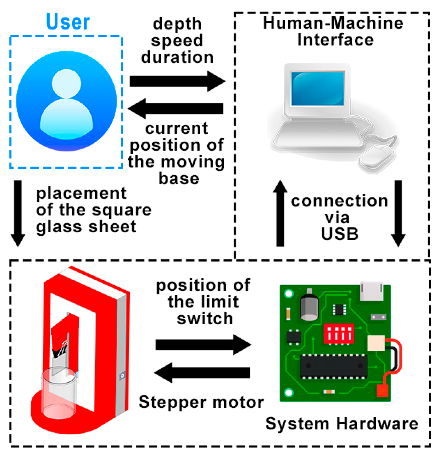
As illustrated in Figure 2, the dip-coater follows a mechatronic architecture with four tightly integrated layers. At the human–machine interface (HMI), the user mounts the square glass substrate on the holder and specifies the process set-points—dip depth, speed, and dwell duration—while monitoring the current stage position. The HMI runs on a PC and exchanges commands and status with the controller via USB. The control-electronics layer generates step/direction pulse trains, supervises safety, and reads the limit-switch for homing and end-stop protection. The actuation & transmission layer employs a stepper motor coupled to a lead screw to convert commanded pulses into precise vertical motion. Finally, the mechanics layer comprises the rigid frame, linear guide, and sample holder aligned with the beaker. This layered organization mirrors that of typical laboratory mechatronic instruments and enables a compact, low-cost, and reproducible dip-coating platform.

2.1. Dip Coater System

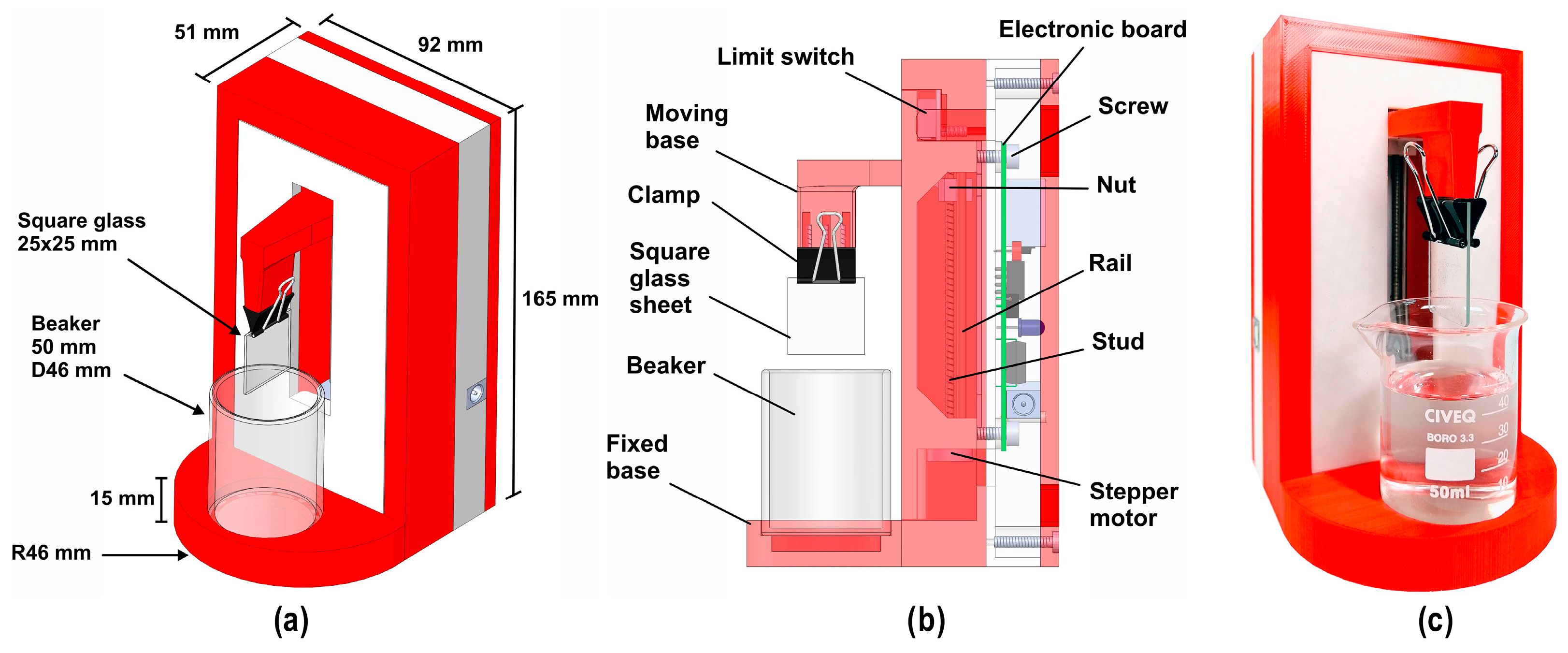
The designed and constructed dip-coating system, hereafter referred to as the CGV USB Dip-Coater, was developed to perform controlled and programmable rise–dwell–fall motion for thin-film deposition applications, see Figure 3. The system integrates mechanical precision with digital control, allowing researchers to customize coating parameters with a high degree of reproducibility.
Structurally, the equipment consists of a custom-built vertical mechanical stage that enables the substrate to move smoothly along a linear path. The motion is actuated by a stepper motor coupled to a lead screw transmission system, ensuring precise vertical translation with minimal mechanical vibration. The motor is driven by a motion controller based on the PIC18F4550 microcontroller, which governs the velocity, acceleration, and dwell-time sequences through preprogrammed control routines. This architecture provides fine-tuned motion control at user-defined speeds, ensuring accurate immersion and emersion cycles during the coating process. The system communicates with a personal computer via a USB interface, enabling real-time parameter configuration and data logging through custom software. The software allows the operator to specify motion profiles, set the number of cycles, and control the immersion speed, dwell time, and withdrawal rate. Designed for laboratory-scale operation, the CGV USB Dip-Coater provides high precision and repeatability while maintaining cost-effectiveness and ease of maintenance. The system’s control architecture and mechanical design facilitate reproducible film deposition under well-defined environmental conditions, ensuring the uniformity of the resulting coatings.
The mechanical layout is a compact vertical frame that integrates the sample holder, beaker platform, and motion train in a single enclosure to ensure alignment and repeatability. The overall external dimensions are 165 mm (height) × 92 mm (width) × 51 mm (depth) with a rounded base of R46 mm and 15 mm thickness, yielding a small laboratory footprint (Figure 3a). The working area is configured for standard small-format experiments: a 25 × 25 mm square glass substrate is retained by a spring clamp and aligned over a beaker station sized for a 50 mL vessel (Ø46 mm, height 50 mm). The geometry provides unobstructed vertical travel for immersion and withdrawal while keeping the mass close to the guide to minimize pitch/roll.
A longitudinal section of the mechanism is presented in Figure 3b. Vertical motion is generated by a stepper-driven lead screw acting on a nut rigidly coupled to the moving base that carries the clamp. A linear rail constrains the carriage and guarantees straightness of motion, while a limit switch located at the upper end is used for homing and over-travel protection. The controller and stepper driver are mounted on an internal electronic board, minimizing wiring and allowing a short, low-inductance path to the motor. The fixed base centers the beaker beneath the slot so that the sample remains collinear with the travel axis throughout the stroke.
The motion subsystem employs a 15 mm diameter two-phase stepper motor (4-wire configuration; Blue A+, Black A−, Red B+, Yellow B−) rated for a driving voltage of 4–9 V DC and a current range of 100–500 mA. The actuator integrates a lead screw of 3 mm diameter and 0.5 mm pitch, providing a sliding stroke of 80 mm with a total rod length of 90 mm. The phase resistance is 25.5 Ω, allowing smooth operation at moderate speeds and low power consumption. The lead screw–nut pair translates rotary motion into linear displacement of the dip-coating arm, ensuring repeatable travel within the 80 mm stroke range.
A photograph of the assembled instrument is shown in Figure 3c, illustrating the final arrangement of the moving base, clamp, and beaker. The structural enclosure, carriage, and fixture components were manufactured by 3D printing in PLA and then hand-assembled using off-the-shelf screws and fasteners, which keeps costs low and enables rapid replacement of wear parts. In operation, the user mounts the 25 × 25 mm square glass on the clamp, places a 50 mL beaker on the platform, executes a homing routine that references the limit switch, and then runs a parameterized rise–dwell–fall trajectory from the HMI. The compact form factor, standardized fixture sizes (25 × 25 mm coupons, 50 mL beaker), and integrated electronics make the system suitable for benchtop coatings and repeatable method development.
The cost analysis of the developed prototype highlights one of its most significant advantages: affordability. As summarized in Table 2, the total cost of materials—including the PLA structure, stepper motor, microcontroller, custom PCB, and basic electronic components—was approximately 50 USD. In comparison, commercial dip-coating systems are priced at considerably higher levels. For instance, the PTL-MM01 has a regular price of 2758.85 USD, while the PTL-MM02 reaches 5287.70 USD. Although those commercial devices may offer advanced features, the low-cost prototype presented here achieves reliable automated dip-coating functionality at less than 2% of the cost of entry-level commercial equipment. This dramatic reduction in cost underscores the viability of the design for teaching laboratories, resource-limited institutions, and early-stage research projects.
The dramatic cost reduction stems from design choices intentionally aligned with low-cost manufacturing: 3D-printed PLA mechanics, a stepper–lead-screw actuator, and a single custom PCB with commodity components. While commercial systems may offer broader envelopes, integrated safety certifications, or advanced features (multi-axis stages, solvent-resistant enclosures, or closed-loop metrology), our results show that the core requirement—repeatable rise–dwell–fall motion with bounded acceleration—can be met reliably at minimal cost. Trade-offs include lower structural stiffness than metal frames, potential chemical compatibility limits of PLA, and the absence of factory calibrations; however, these can be mitigated with simple upgrades (alternate materials, enclosure add-ons, encoder options) without fundamentally altering the cost profile. Importantly, the total cost of ownership remains low: spare parts are inexpensive, the design is serviceable, and the open architecture facilitates incremental enhancements. Consequently, the system occupies a useful niche—bridging proof-of-concept research and instructional use—while preserving a clear upgrade path toward higher performance as application needs evolve.

2.2. System Hardware

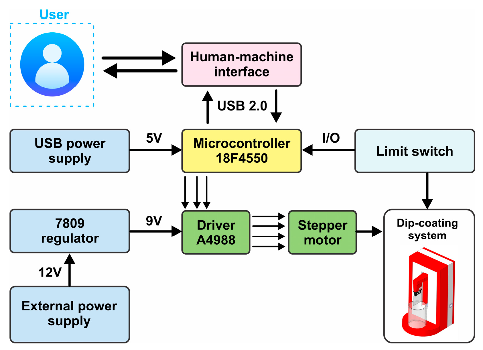
The block diagram of the hardware is shown in Figure 4. It comprises a USB-powered control path for real-time communication and logic, and a separately regulated power path for the motor drive.
The main electrical/electronic elements are:
  • Microcontroller: Serves as the central controller and USB 2.0 device. It receives set-points from the HMI (speed, depth, dwell), executes homing/limits logic, and generates step/direction/enable signals for the driver using timer-interrupt pulse trains. The PIC is powered from the USB 5 V rail and provides the digital I/O for the limit switch.
  • Stepper driver: A chopper, current-regulated driver that translates the PIC’s step/direction commands into phase currents for the motor. Microstepping is configurable; the enable line is tied to the PIC for controlled start/stop. The driver is powered from a 9 V rail to reduce dissipation while maintaining torque margins.
  • Stepper motor: Provides the linear actuation through the lead screw (described in Section 2.1). A shared signal ground is maintained between the driver and the microcontroller to ensure clean edge timing.
  • Limit switch: A normally closed end-stop used for homing and travel protection. It is wired to a PIC digital input and monitored continuously; triggering halts pulse generation and initiates the homing routine.
  • Power subsystem: Two isolated paths: (i) the USB 5 V line powers the PIC and the USB interface; (ii) an external 12 V supply feeds a 7809 linear regulator that provides a clean 9 V rail for the A4988. Bulk and local decoupling capacitors are placed near the driver and PIC; grounds are star-connected at the driver input to minimize noise coupling.
  • HMI: Runs on a PC and exchanges commands/status with the PIC over USB 2.0. The HMI displays the current position and allows the user to start homing, set the stroke, cruise speed, acceleration time, and dwell, and execute the rise–dwell–fall trajectory.
This partition keeps logic and communication on a low-noise, USB-powered domain while supplying the motor from a dedicated, well-regulated rail—improving timing determinism, electrical robustness, and safety.
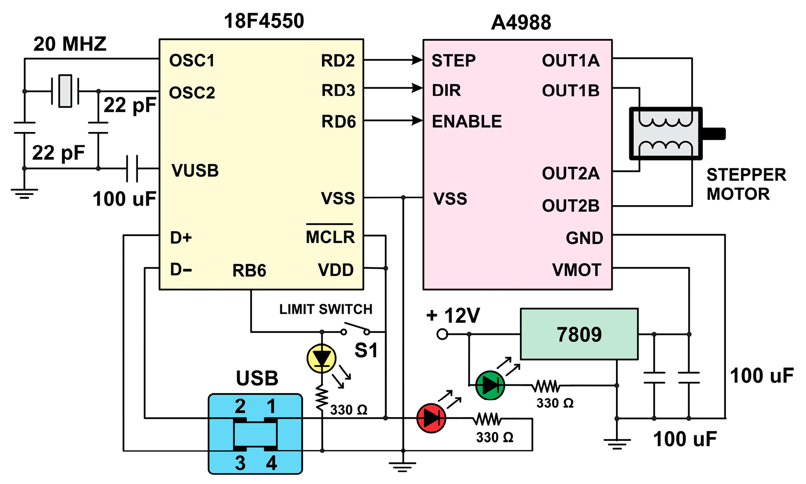
Figure 5 shows the wiring that interfaces a PIC18F4550 microcontroller with an A4988 stepper driver using separate supplies for logic and motor power. The MCU is clocked by a 20 MHz crystal (22 pF load capacitors) and powered at VDD = 5 V from the USB rail; VUSB is bulk-decoupled with 100 μF to stabilize bus transients. Motion commands are issued on three digital outputs—STEP (RD2), DIR (RD3), and ENABLE (RD6)—and routed to the A4988; logic grounds (VSS) are common between devices to ensure clean edge timing. The limit switch S1 is connected to a protected MCU input and used for homing and over-travel detection. The USB connector also provides the D+/D− data lines for the HMI link.
As also depicted in Figure 5, the motor power path is independent: an external 12 V source feeds a 7809 linear regulator whose 9 V output supplies the driver’s VMOT rail (motor side). 100 μF bulk capacitors are placed at the regulator and near the driver to limit current ripple and suppress switching transients. Three status LEDs report system state—yellow indicates the stage is at home, red confirms USB/5 V present (thus MCU powered at VDD), and green indicates the motor supply is energized—providing quick visual diagnostics while preserving electrical separation between logic and actuation. This partition improves noise immunity and supports deterministic pulse generation for precise dip-coating motion.
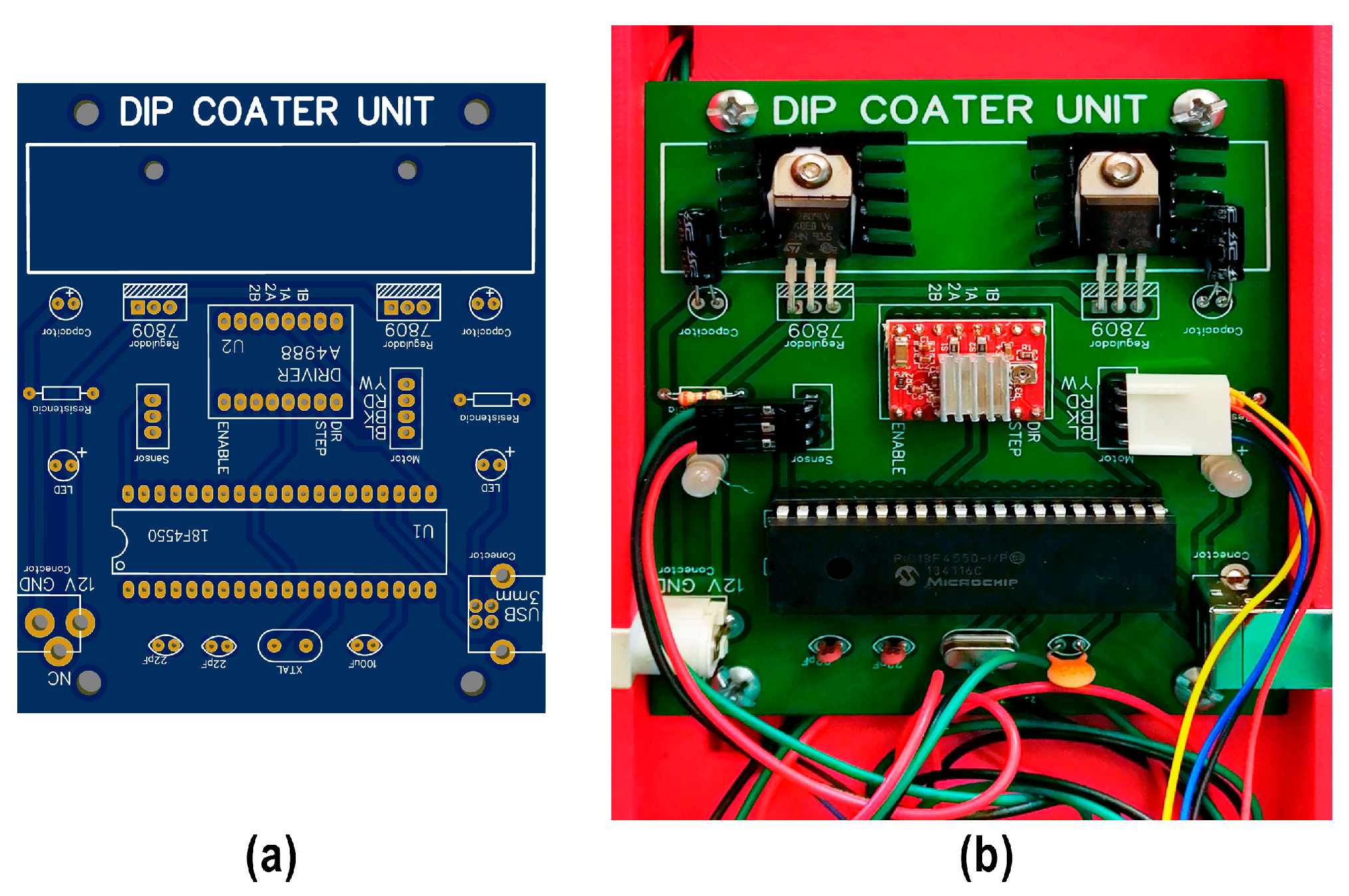
Figure 6a shows the custom two-layer PCB designed for the dip-coater: it integrates the PIC18F4550, an A4988 stepper-driver carrier, dual 7809 regulators with heat sinks, the USB connector, headers for the limit switch and stepper motor, status LEDs, and bulk/decoupling capacitors arranged to separate logic and motor currents. Figure 6b shows the hand-assembled board inside the instrument; bring-up verified proper operation via continuity checks, rail validation, I/O tests, LED status confirmation, and oscilloscope inspection of pulse timing followed by a motor test to set current and microstepping.

2.3. Human–Machine Interface

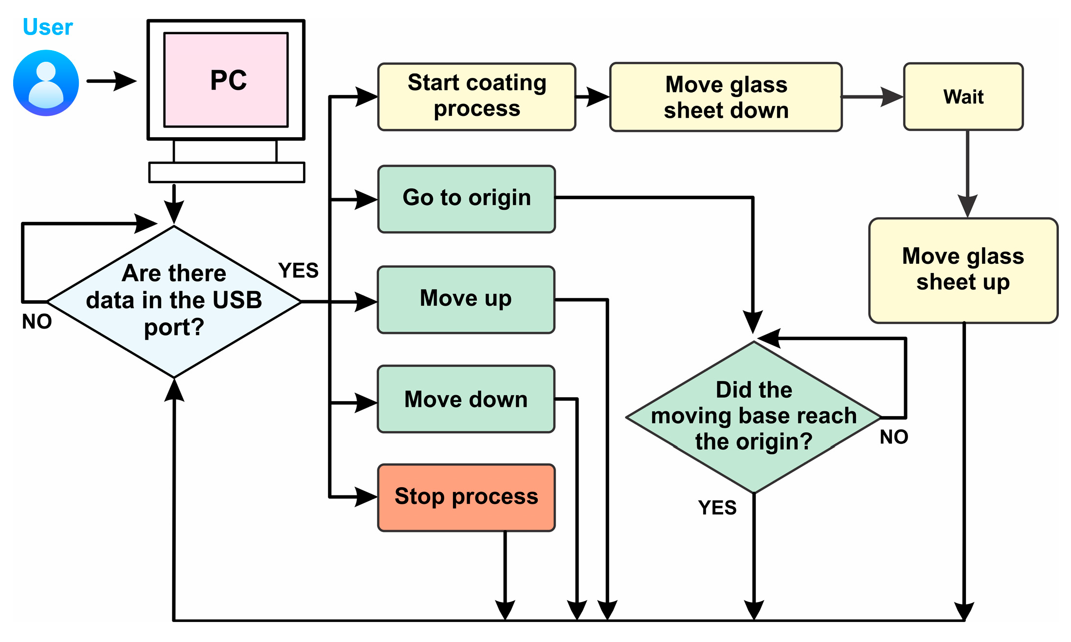
Figure 7 summarizes the HMI–controller interaction used to execute a coating cycle. The PC application allows the user to specify the set-points—dip depth, cruise speed, and dwell time—and to issue high-level commands (“Go to origin”, “Move up”, “Move down”, “Start coating process”, “Stop process”). The microcontroller runs a polling loop (Are there data in the USB port?): when a command frame is available it is parsed and acknowledged, otherwise the firmware remains in an idle state while reporting the current stage position and system status. The “Go to origin” routine repeatedly drives the carriage upward until the limit switch is asserted; origin status is latched and returned to the HMI for display. When “Start coating process” is triggered, the controller executes a parameterized rise–dwell–fall sequence: (i) Move glass sheet down at the commanded speed to the requested immersion depth; (ii) Wait for the programmed dwell; and (iii) Move glass sheet up to withdraw the sample. At any time, “Stop process” preempts motion, disables the driver, and returns the system to a safe idle.
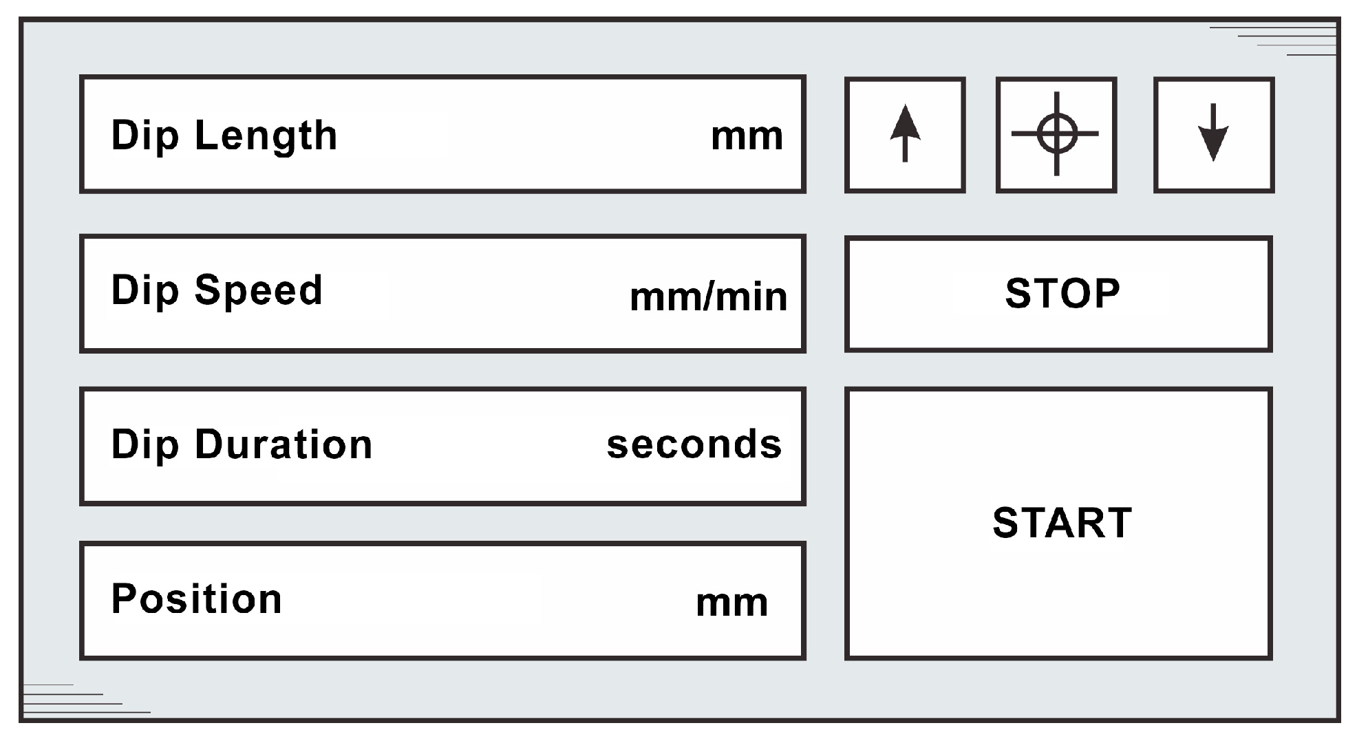
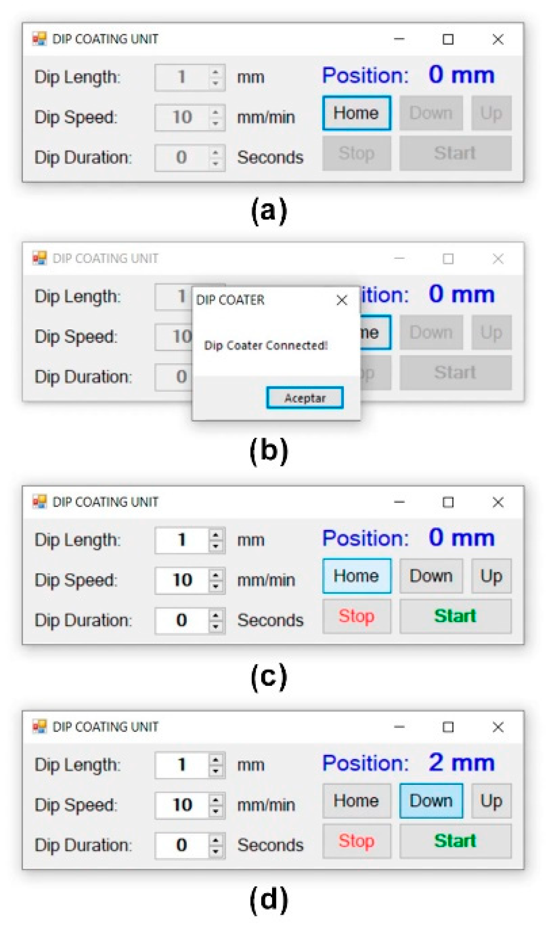
A well-designed GUI is essential because it translates experimental intent into safe, repeatable machine actions. By exposing only the required parameters with explicit units and bounds, it reduces entry errors and standardizes procedures across users—critical for reproducibility. Figure 8 shows the GUI concept, implemented in Microsoft Visual Studio. It is intentionally minimalist: only the essential inputs—Dip Length (mm), Dip Speed (mm/min), and Dip Duration (s)—are exposed, alongside a read-only Position (mm) readout for real-time feedback. Three large icons provide direct manual control (up, home/origin, down), while START and STOP occupy prominent buttons for unambiguous execution and immediate abort.

2.4. Control

The end-effector motion is modeled using a bounded-acceleration, trapezoidal-velocity profile that executes a rise–dwell–fall cycle under open-loop step counting referenced by homing. Let x ( t ) be the vertical position; x 0 the lower stop; L the commanded travel; t a the ramp (accel/decel) time; t c the constant-speed time; v m a x the cruise speed; a m a x the (piecewise-constant) acceleration magnitude; T and T the rise and fall durations; and T d w e l l the dwell time at depth. Feasibility and timing follow:
a m a x = v m a x t a
L = a m a x t a 2 + v m a x t c
T = 2 t a + t c
T = 2 t a + t c
For compact notation, the local time variables used in the deceleration segments are defined as follows:
τ = t t a + t c
During the rise (upward motion) the position, velocity, and acceleration are
x t = x 0 + 1 2 a m a x t 2 , 0     t < t a , x 0 + 1 2 a m a x t a 2 + v m a x t t a , t a     t < t a + t c , x 0 + 1 2 a m a x t a 2 + v m a x t c + v m a x τ 1 2 a m a x τ 2 , t a + t c     t     T ,
v t = a m a x t , 0     t < t a , v m a x , t a     t < t a + t c , v m a x a m a x τ , t a + t c     t     T ,
a t = + a m a x , 0     t < t a , 0 , t a     t < t a + t c , a m a x , t a + t c     t     T ,
This phase contains a constant acceleration + a m a x , a constant-speed cruise, and a symmetric deceleration a m a x that arrests the motion at x 0 + L ; the area under v t over the rise equals L .
During the dwell the end-effector remains at depth:
x ( t ) = x 0 + L
v ( t ) = 0
a ( t ) = 0
For the return, the local time variables for the fall are defined as follows:
t = t T + T d w e l l
μ = t t a + t c
During the fall (downward motion) the kinematics are
x t = x 0 + L 1 2 a m a x t 2 , 0     t < t a , x 0 + L 1 2 a m a x t a 2 + v m a x t t a , t a     t < t a + t c , x 0 + L 1 2 a m a x t a 2 + v m a x t c v m a x μ + 1 2 a m a x μ 2 , t a + t c     t     T ,
v t = a m a x t , 0     t < t a , v m a x , t a     t < t a + t c , v m a x a m a x μ , t a + t c     t     T ,
a t = a m a x , 0     t < t a , 0 , t a     t < t a + t c , + a m a x , t a + t c     t     T ,
This phase mirrors the rise with opposite signs; the area under v t over the fall equals L , giving zero net displacement over the full cycle. The cycle time is
T = T + T d w e l l + T
In the model, S is the step–displacement conversion factor (the axis kinematic gain), expressed in steps/mm and indicating how many motor steps produce 1 mm of travel. For a direct-drive screw,
S = N m p
where N is the motor’s full steps per revolution, m the microstepping factor, and p the screw lead (mm/rev). This factor maps continuous kinematics to the pulse domain:
f s t = S   v ( t )
f ˙ s t = S   a ( t )

3. Simulation Results

Simulating the motion profile before building a mechatronic prototype is crucial: it exposes feasibility constraints (speed/acceleration limits, step rates), validates the state logic, and lets us tune stroke time and waveform shape to the coating task without risking hardware. This section provides a general verification of the motion programs prior to hardware testing. Using the mathematical model, triangular (fast dip–withdraw, no dwell) and trapezoidal (dip–soak–withdraw with dwell) commands are generated, producing reference traces of position, velocity, and acceleration. The simulations check feasibility (stroke and total time), clarify expected waveform shapes (linear position segments, piecewise-constant velocity, and idealized switching in acceleration), and supply baseline signals for later comparison with experiments.
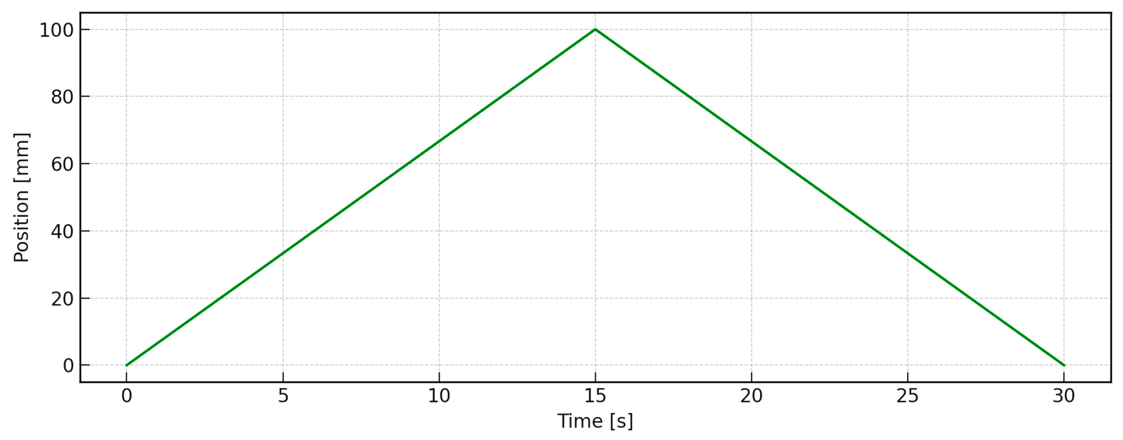
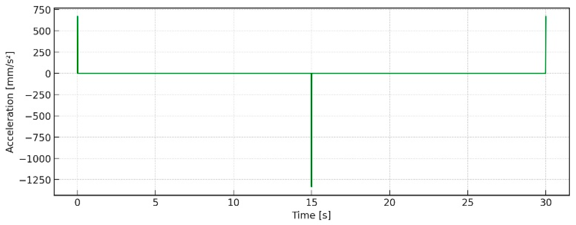
Prior to hardware testing, an ideal “fast dip–withdraw” cycle was simulated, employing a triangular position command with a stroke of L = 100   m m and a total cycle time of T = 30   s (no dwell). The half-cycle is 15 s, so the carriage moves at constant speed + 6.667   m m / s from 0 to 100 mm and then 6.667   m m / s back to 0 mm, with initial/terminal conditions x 0 = 0   m m , x 15 = 100   m m , x 30 = 0   m m . Acceleration is identically zero except at the switching instants t = 0,15,30   s , where it is impulsive in the ideal model; in practice these impulses would be replaced by short ramps within actuator limits. The profiles are computed in closed form and sampled at t = 0.01   s . Figure 9 shows the commanded position: a perfect triangle with linear ascent from 0 to 100 mm in 15 s and linear descent back to 0 mm by 30 s. The waveform verifies that stroke and time bounds are met exactly, providing a simple reference for open-loop step counting and for checking end-stop logic in the sequential controller.
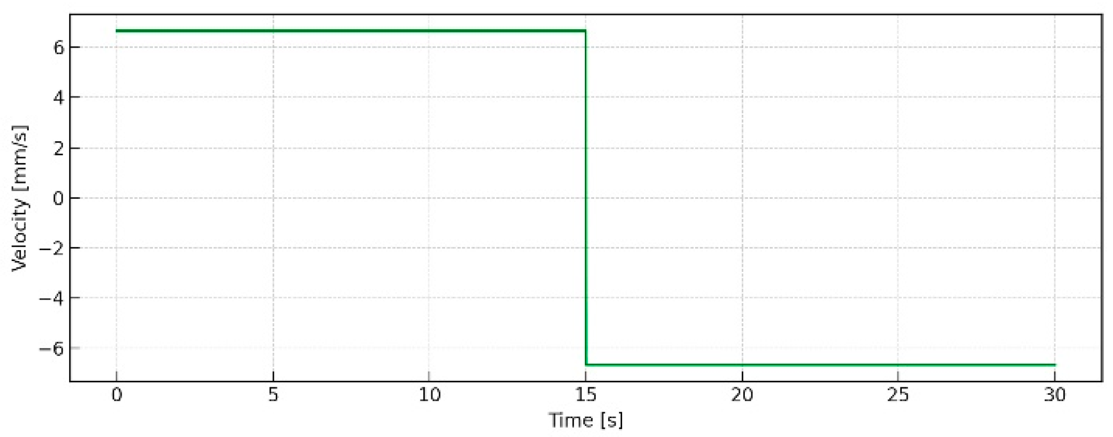
Figure 10 displays the corresponding velocity, which is piecewise constant at + 6.667   m m / s during the first half of the cycle and 6.667   m m / s during the second half, with a sign inversion at t = 15   s . This constant-magnitude speed is attractive when only a quick down/up action is needed (e.g., rapid immersion and immediate withdrawal) and when uniform interface speed during each leg is preferred.
Figure 11 shows the ideal acceleration implied by the triangular position: it is zero everywhere except at the switching instants, where it collapses to impulses (step changes in velocity). These spikes are a mathematical idealization; a real actuator must respect finite acceleration. In practice, the same cycle time can be realized by replacing the impulses with short ramps (trapezoidal velocity or jerk-limited S-curves) chosen within motor/driver limits, while preserving the “fast lower–fast raise” behavior that the user may require.
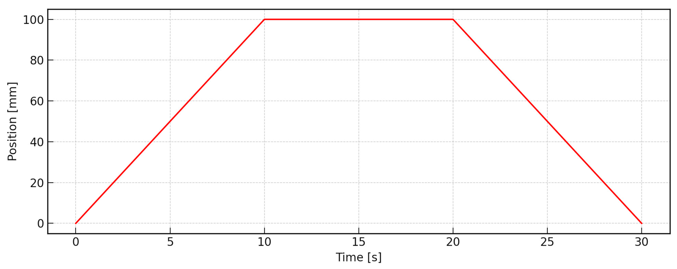
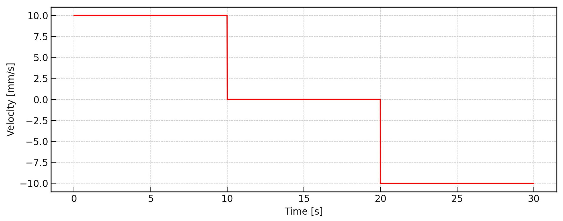
To emulate a dip–soak–withdraw cycle, a trapezoidal position command with linear rise, dwell, and linear fall segments was simulated. The carriage starts at x 0 = 0   m m , reaches L = 100   m m in T = 10   s , holds for T d w e l l = 10   s , and returns to x 30 = 0   m m in T = 10   s (total T = 30   s ). The corresponding constant speeds are + 10   m m / s during the rise, 0   m m / s during the dwell, and 10   m m / s during the fall. Profiles were computed analytically and sampled at t = 0.01   s . Figure 12 shows the piecewise-linear ascent from 0 to 100 mm over 0–10 s, a flat plateau at 100 mm for 10–20 s, and a linear return to 0 mm over 20–30 s—capturing the common requirement to reach depth, dwell for wetting/reaction, and withdraw at a controlled rate.
As plotted in Figure 13, the velocity is piecewise constant: + 10   m m / s during the rise, 0   m m / s during the dwell, and 10   m m / s on the return, with instantaneous transitions at 10 s and 20 s.
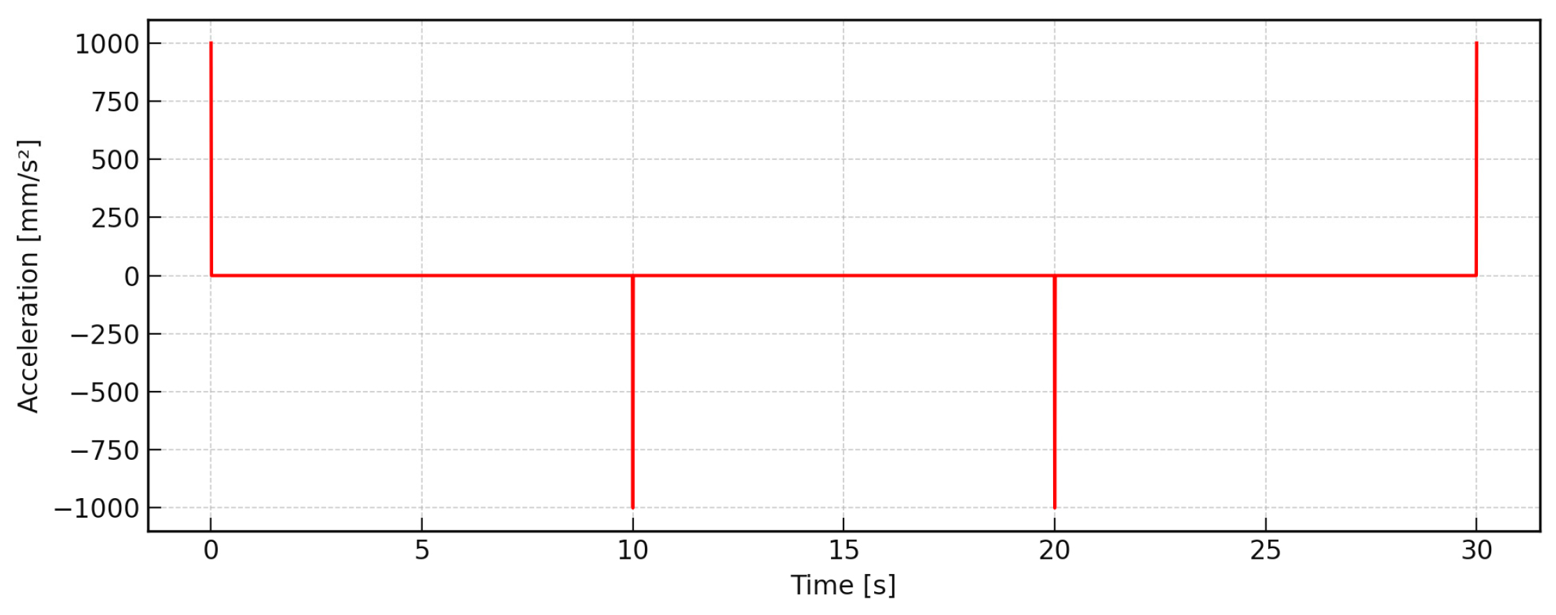
Figure 14 depicts the idealized acceleration: zero except for impulses at the segment boundaries (0, 10, 20, 30 s) that represent instantaneous velocity changes. On hardware, these impulses are replaced by short finite-acceleration ramps sized to motor torque/current limits while preserving the commanded dwell and segment speeds.
The two simulations represent distinct operating modes of a dip-coater and define the design space that must be satisfied before hardware implementation. The triangular case encodes a rapid dip–withdraw with no dwell: position is a perfect triangle, which implies a piecewise-constant velocity of ± 6.667   m m / s across each leg and ideal, impulsive changes in acceleration at the start, midpoint, and end. This mode is attractive when the user simply needs to go down and up quickly—for example, fast wetting, rinse, or clearance operations—and when uniform interface speed during each leg is preferred. In practice, the impulses are replaced by short acceleration ramps; doing so slightly rounds the position corners but preserves the constant-speed segments. The trapezoidal case adds a 10 s dwell at the target depth while keeping a 30 s total cycle. Position rises linearly to 100 mm in 10 s, holds, and then returns linearly; the velocity is piecewise constant at + 10 , 0 , 10   m m / s .
This pattern is better aligned with many coating protocols that require time at depth for wetting, adsorption, or reaction. From a controls standpoint, the dwell segment simplifies timing (the pulse train halts cleanly), and the leg speeds are higher than the triangular case, which can shorten exposure to transient regimes at the liquid interface. As with the triangular profile, real hardware replaces the ideal velocity steps with finite acceleration ramps (trapezoidal-velocity or jerk-limited S-curves) sized to the motor torque/current limits. Both motion programs are straightforward to realize with a stepper–lead-screw actuator and provide deterministic travel once the axis is homed. The triangular program minimizes residence at peak depth and operates at a lower constant speed, which is advantageous for delicate samples or hardware with limited step-rate capability. The trapezoidal program inserts a controlled dwell that enables precise process synchronization (e.g., triggering valves or timers during the soak).
In both cases, replacing the ideal velocity steps with bounded-acceleration ramps (or jerk-limited S-curves) mitigates jerk, reduces vibration, and protects the mechanics without materially changing the commanded stroke or the total cycle time. With the simulation envelope established and parameter choices justified, the next step is the experimental validation of the prototype. Both motion programs are executed on the instrument to log position, velocity, and acceleration data, calibrate the steps-per-millimeter factor ( S ), and quantify tracking and repeatability while assessing coating quality as a function of speed and dwell time.

4. Experimental Results

This section presents a general validation of the prototype.

4.1. GUI Operation and Functional Verification

The GUI was employed to execute the programmed motion sequences, verifying the operational flow—including USB detection, homing, jog, parameter entry, and Start/Stop—and recording the stage position, velocity, and acceleration. Figure 15 summarizes the GUI operating sequence as observed during routine use.
In the pre-connection state (a), the application waits for the dip-coater to enumerate on the USB bus; all controls are intentionally disabled to prevent unintended motion. Once the controller is recognized (b), a modal message (“Dip Coater Connected!”) confirms the link and the interface enables user controls. When the operator presses “Home” (c), the firmware drives the carriage upward until the limit switch is actuated; the GUI then sets the Position readout to 0 mm, establishing the reference for subsequent moves. In jog mode (d), pressing “Down” commands a downward motion at the selected “Dip Speed”, while the “Position” field updates in real time; safety interlocks remain active and “Stop” is available at all times. After homing, the user enters the process parameters—Dip Length, Dip Speed, and Dip Duration—and presses “Start”; the controller then executes the coating cycle (descent to the specified depth, dwell for the programmed time, and ascent to withdraw the sample), while inputs unrelated to safety are latched to prevent accidental changes and the “Position” readout continues to provide feedback until completion. At any moment, the operator may press Stop to immediately preempt the sequence, disable motion, and return the system to a safe idle state. Operationally, the GUI behaved deterministically: USB detection, homing, jog, parameter entry, and Start/Stop executed as designed, and the origin interlock prevented motion beyond travel limits. Taken together, these results validate both the mechanism (stepper–lead-screw stage) and the control stack (sequential logic plus bounded-acceleration pulse generation) for typical dip-coating sequences. The prototype delivers deterministic strokes, accurate dwell timing, and bounded accelerations while using commodity electronics and 3D-printed structure. Remaining improvements—such as optional jerk-limited profiles or on-axis encoders for closed-loop verification—are straightforward extensions.
By delegating the main computational workload to the external computer, the embedded hardware requirements were minimized, reducing the need for higher-cost microcontrollers or additional processing modules. Furthermore, the exclusive use of a software-based interface eliminated the need for physical buttons, keypads, or displays on the instrument itself, further lowering the bill of materials. This approach not only reduced costs but also simplified assembly and maintenance, while preserving flexibility, since updates or new functions can be added directly through the software without hardware modifications. In this way, the GUI not only enhanced usability and reproducibility but also directly contributed to keeping the total prototype cost as low as possible.

4.2. Calibration and Error Analysis

System calibration was carried out to verify the correspondence between the programmed displacement and the actual linear motion of the stage. The stepper motor and lead-screw assembly were evaluated over a total travel distance of 100 mm using a digital caliper with ±0.01 mm resolution. For each commanded step count, the resulting displacement was recorded, and a linear regression analysis between programmed and measured values confirmed excellent correlation (R2 > 0.999). The average positional deviation was less than 0.5 mm, corresponding to a relative error below 1% across the entire operating range. Motion repeatability was evaluated by performing ten consecutive dipping cycles at a withdrawal speed of 50 mm min−1. The measured standard deviation of the final position was 0.3 mm, indicating stable positioning across repeated operations. The velocity accuracy was further verified using high-frame-rate video analysis, confirming that the instantaneous withdrawal speed remained within ±0.8% of the target value. These results demonstrate that the actuator–controller integration provides sufficient precision and stability for reproducible thin-film deposition. The small residual deviations observed at direction reversals are mainly attributed to mechanical backlash in the lead-screw assembly rather than to electronic or firmware limitations. Future system iterations will incorporate closed-loop feedback or backlash compensation algorithms to further enhance accuracy during extended operation.

4.3. Coating Performance Tests

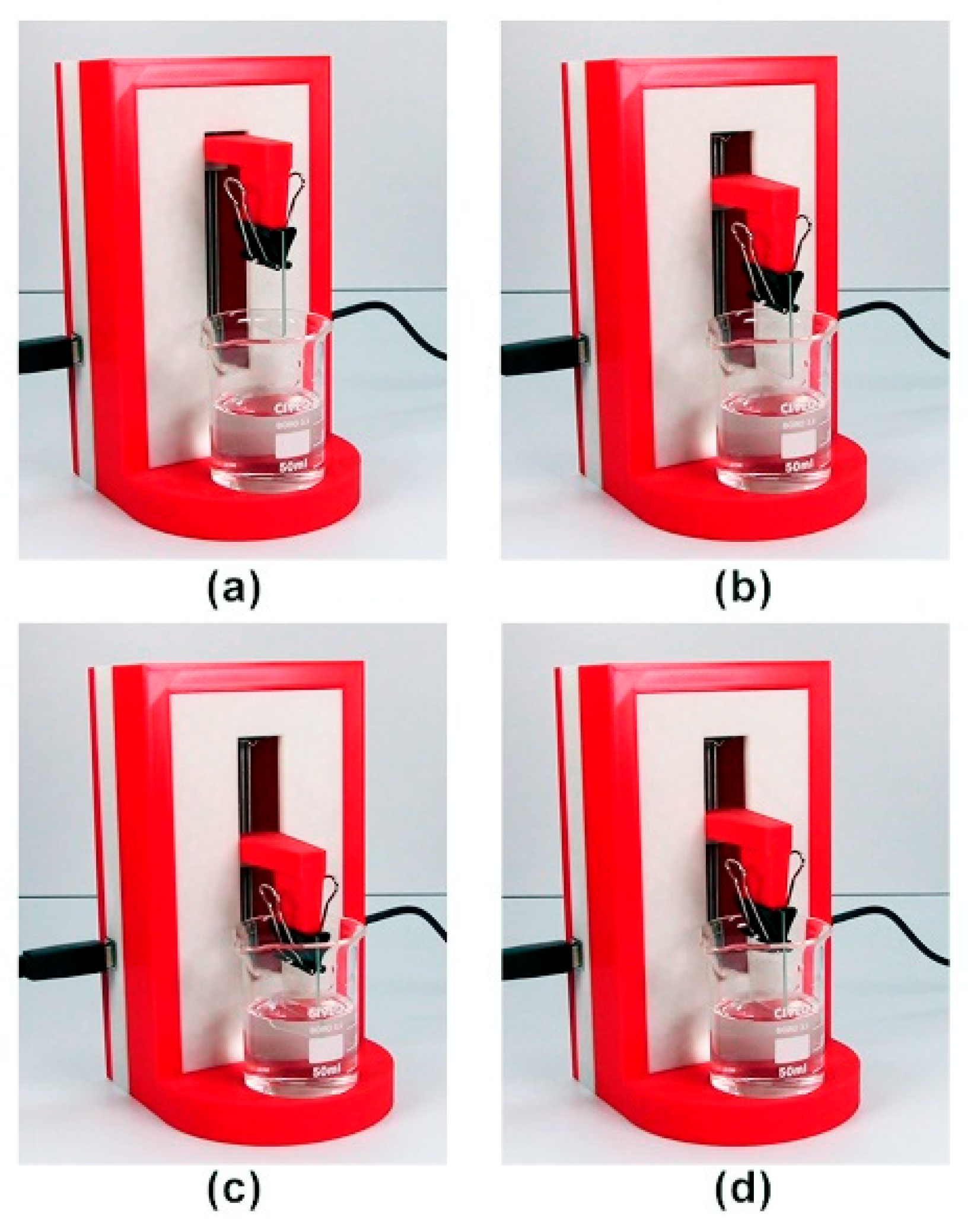
Figure 16 shows the dip-coater’s operating sequence under GUI control after the user presses “Start” with dip length, speed, and dwell already set. (a) The system is at home (0 mm) and ready. (b) The carriage moves down at the commanded speed to the target immersion depth. (c) The specimen remains submerged for the programmed dwell time. (d) The carriage withdraws the sample and returns toward home. Throughout the cycle, the GUI streams real-time position feedback and the “Stop” command remains available to immediately abort the process if required.
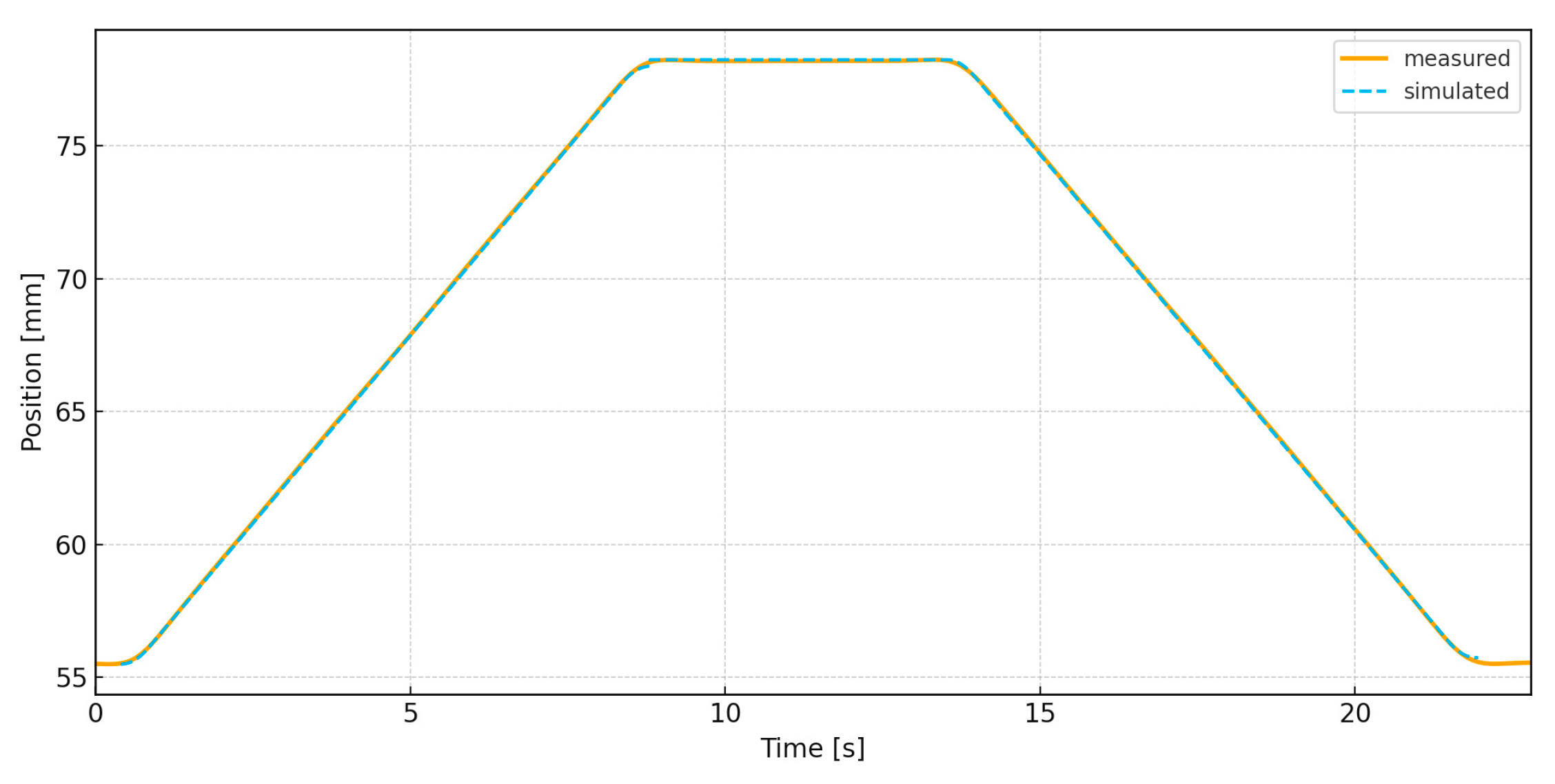
The run was programmed from the GUI as a rise–dwell–fall cycle with an initial offset near 55.6   m m , a target depth around 78.3   m m , and a resulting stroke of 22.7   m m . The stage moved up at 2.7 2.9   m m / s , held at depth for 5   s , and then returned at the same speed; the full cycle lasted 22 23   s . Position, velocity, and acceleration were measured with Kinovea, a free video-analysis tool that offers calibrated 2D tracking, automatic kinematic computation, and CSV export. The experimental test was recorded using a GoPro HERO 11 camera (GoPro Inc., San Mateo, CA, USA). The recorded video was done at 1080p/240fps (sampling period of 0.0042 s). The camera viewed the axis orthogonally; a millimetric fiducial provided spatial calibration, and a high-contrast marker on the moving base enabled robust tracking. Kinovea was selected because it is non-contact, low-cost, fast to deploy, and sufficiently accurate for millimeter-scale motions at standard frame rates—consistent with the low-cost ethos of the instrument—while yielding reproducible datasets for direct comparison against the simulated reference generated with the same parameters and finite-acceleration corners.
Figure 17 shows measured (solid orange) and simulated (dashed blue) position versus time. The two traces almost completely overlap: the ascent and descent slopes match closely, and the plateau is aligned in level and duration, indicating that the identified speed, stroke, and dwell capture the experiment well. Small, smooth roundings at the turning points reflect the bounded acceleration used in the drive and minor mechanical compliance; a slight phase lag of only a few tens of milliseconds is visible at the slope changes, consistent with timestamping/measurement latency. Overall, the agreement validates the position model for this motion program.
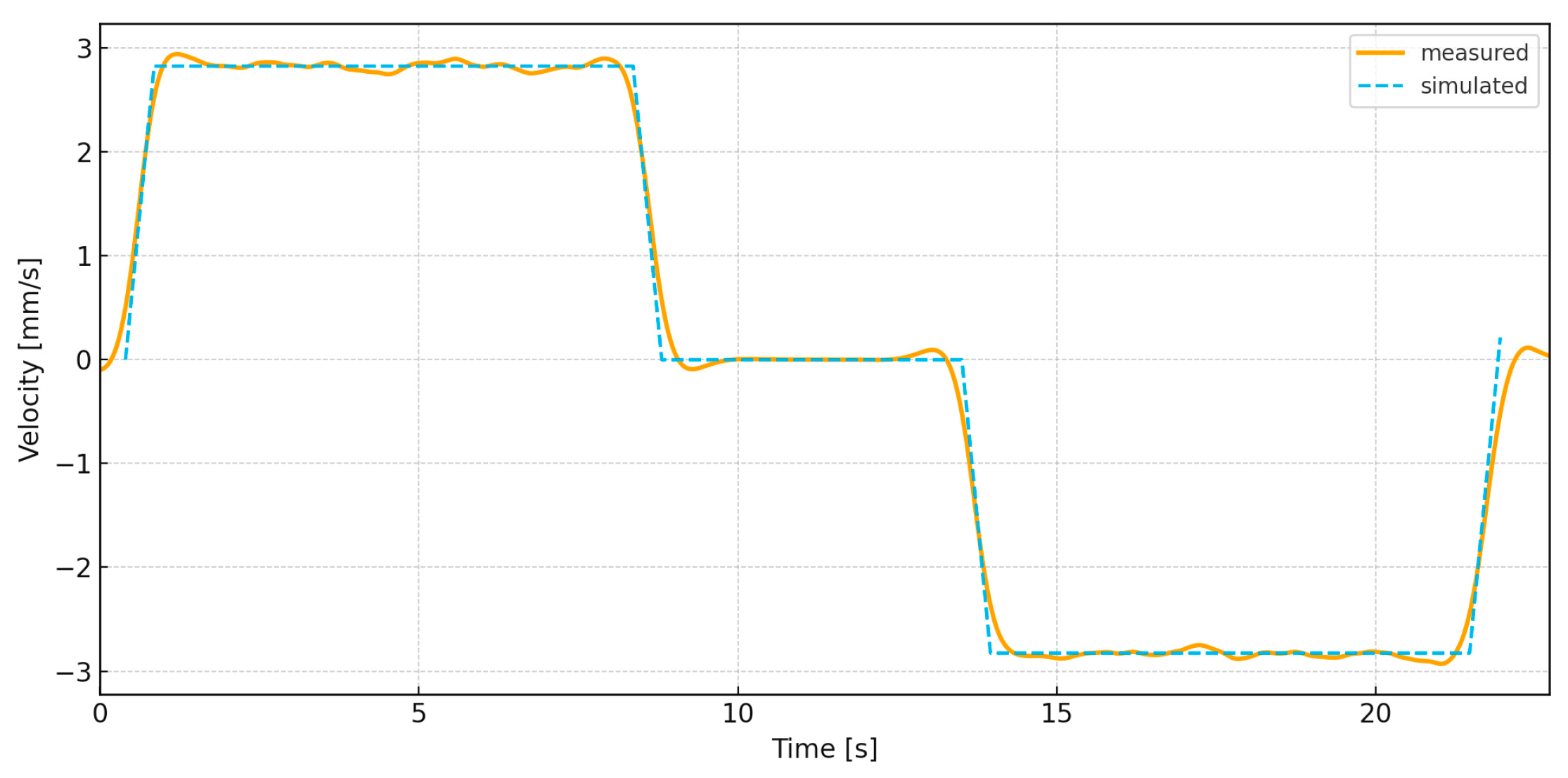
Figure 18 shows the velocity comparison between the measured (orange) and simulated (blue dashed) profiles for the rise–dwell–fall program. During the upstroke ( 0 8.7   s ), the measured speed ramps to a steady 2.8 2.9   m m / s , closely matching the reference; the small ripple ( ± 0.05 0.1   m m / s ) is consistent with differentiation noise and microstepping ripple. Entering the dwell, a slight phase lag and brief undershoot are visible, after which the velocity remains effectively zero (< 0.1   m m / s ) over 9 14   s , confirming the hold at depth. At the start of the downstroke ( 14   s ), the measured trace shows a short overshoot to about 3.0   m m / s before settling near 2.8 to 2.9   m m / s , again tracking the simulated constant segment. The final stop near 22 22.5   s exhibits a small rebound but converges to zero promptly. Overall, the measured velocity follows the commanded piecewise-constant profile with only minor, physically expected deviations at the switching instants.
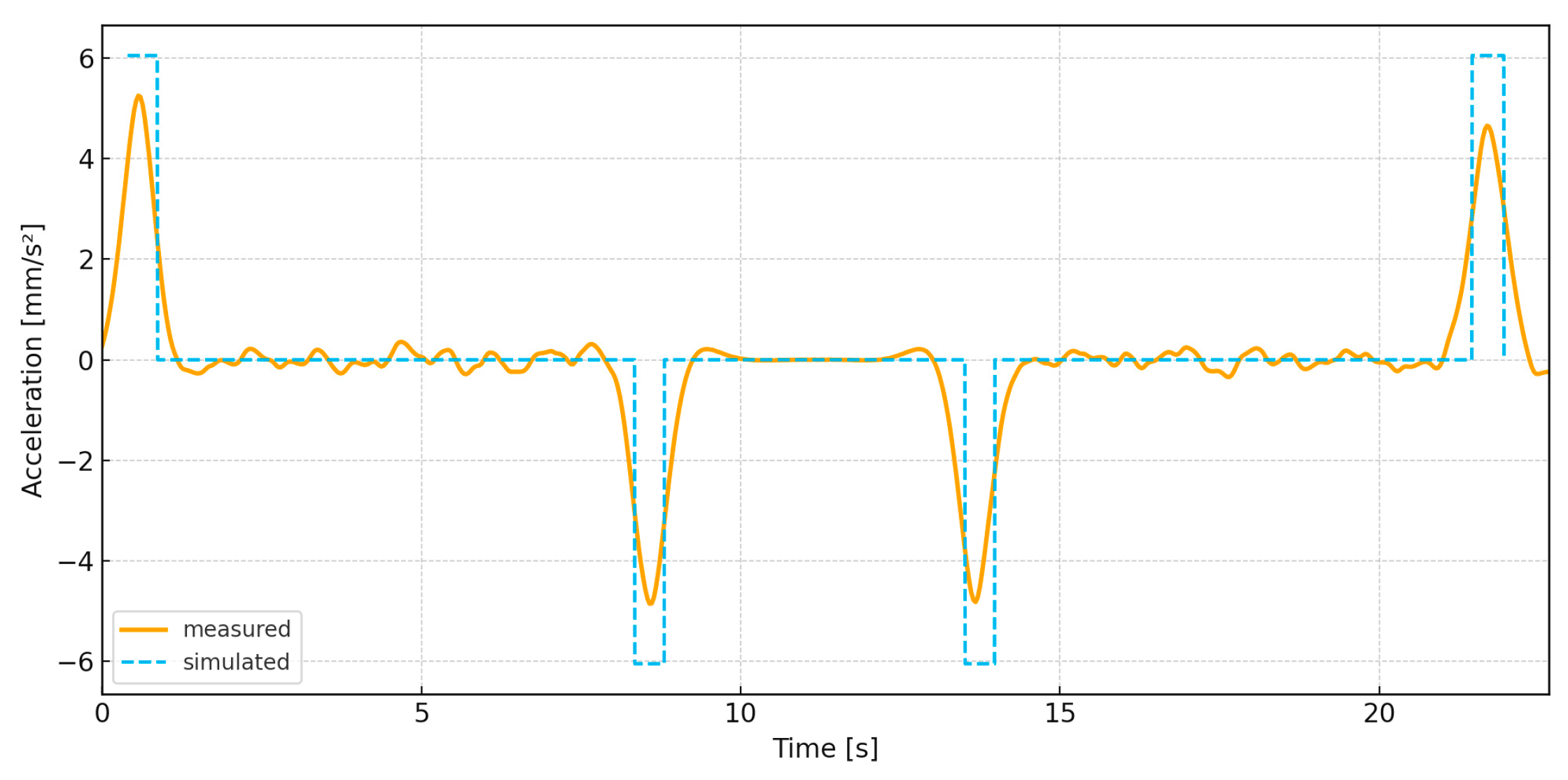
Figure 19 compares the acceleration traces. The dashed curve indicates the simulated switching instants—start, brake into dwell, brake out of dwell, and final stop. The four measured extrema coincide temporally with these events, with peak magnitudes of roughly ± 5 6   m m / s 2 . Between events, acceleration oscillates about zero with low-amplitude ripple, consistent with numerical differentiation, microstepping torque ripple, and minor structural compliance. Overall, the controller issues the expected braking/starting actions at the correct times; the small amplitude discrepancies are attributable to smoothing and measurement artifacts rather than systematic timing errors.
The experiments confirm that the prototype reproduces the commanded motion with high fidelity while maintaining a simple, robust workflow. The position comparison in Figure 17 shows near-complete overlap between measured and simulated traces across the rise–dwell–fall cycle: slopes match, the plateau level and duration are preserved, and only modest corner rounding appears—consistent with the bounded accelerations applied by the controller and small structural compliance. The velocity comparison in Figure 18 likewise tracks the piecewise-constant reference closely; the observed ripple of roughly ± 0.05 0.1   m m / s on the steady segments and the brief overshoot at the switching instants are expected from microstepping torque ripple and numerical differentiation of video data. The acceleration plot in Figure 19 aligns the four braking/starting events in time, with peak magnitudes on the order of ± 5 6   m m / s 2 and low-amplitude fluctuations around zero elsewhere, indicating that the finite-acceleration strategy triggers at the correct instants.

4.4. Validation

Although the present work did not include direct experimental characterization of the coatings produced with the CGV USB Dip-Coater, this system has been previously validated and documented. Its use across different materials and experimental contexts demonstrates both its mechanical robustness and its capacity to produce uniform and reproducible coatings under controlled environmental and kinematic conditions. In the study conducted by Llorente-García et al. [41], the CGV USB Dip-Coater was employed to deposit TiO2-based films onto clean glass substrates. The obtained results confirmed the high quality of the deposited layers, validating the system’s capability to maintain a constant immersion and emersion speed during the coating process. A second validation came from Vital-Grappin et al. [42], who used the same dip-coating system to fabricate nitrogen- and carbon-doped TiO2 and ZnO thin films for photocatalytic applications aimed at microplastic and nanoplastic degradation. In their work, the CGV USB Dip-Coater operated at an immersion and emersion rate of 100 mm/min, enabling precise control of film thickness and surface uniformity. The resulting coatings exhibited excellent optical transparency, mechanical adhesion, and photocatalytic activity under visible light irradiation—further confirming the equipment’s versatility for nanostructured semiconductor fabrication. Together, these studies provide robust evidence of the experimental reliability, repeatability, and scientific applicability of the CGV USB Dip-Coater. The consistent operating parameters and the reproducibility of the resulting coatings across multiple investigations support the technical soundness of the system and indirectly validate its performance in the present study. Its successful deployment in different research settings—ranging from sol–gel derived TiO2 coatings to green-synthesized semiconductor films—positions the CGV USB Dip-Coater as a practical and validated tool for controlled thin-film preparation in advanced materials and surface engineering research.

5. Conclusions

This paper presented the design and validation of a low-cost automated dip-coater for laboratory applications. The prototype integrates a 3D-printed PLA structure, a stepper–lead-screw actuator driven by a PIC18F4550/A4988 electronics stack, and a minimalist GUI developed in Visual Studio that enforces a safe sequential workflow. A mathematical model was derived to generate triangular (fast dip–withdraw) and trapezoidal (dip–soak–withdraw) motion programs, which were mapped to pulse trains via the steps-per-millimeter factor. Simulation results established feasibility and provided reference trajectories, while experimental trials—measured non-contact with Kinovea—confirmed close agreement in position, velocity, and acceleration. The prototype demonstrated deterministic strokes, accurate dwell timing, and bounded accelerations with only minor deviations at switching instants, validating that reproducible dip-coating motion can be achieved with low-cost components and a simple control architecture. Regarding cost, the prototype’s bill of materials is approximately USD 50, corresponding to 1–2% of the price of entry-level commercial units. This advantage is enabled chiefly by a PC-hosted GUI and the absence of physical control hardware. Despite its minimal cost, the system met functional and safety requirements, making it suitable for teaching laboratories, resource-constrained environments, and early-stage research, with clear potential for modular upgrades.
Future work will focus on extending the present system beyond mechanical validation toward experimental coating evaluation and process optimization. Although this study did not include direct coating experiments, microscopic film analyses, or sensitivity studies on motion parameters, these aspects represent key directions for subsequent research. Planned efforts will include a systematic sensitivity analysis of motion parameters—such as withdrawal speed, acceleration, and dwell time—and their effect on motion repeatability and coating uniformity. Additional work will involve experimental coating trials with functional materials (e.g., TiO2, ZnO, and sol–gel films) to assess film thickness, morphology, and adhesion through optical and electron microscopy. Future developments will also address the implementation of jerk-limited and adaptive motion profiles to minimize vibration, closed-loop sensing for position feedback, and high-rate data acquisition with GUI scripting for automated batch processing. Complementary improvements will explore environmental control (temperature and humidity) to enhance coating reproducibility. Collectively, these efforts aim to transform the current prototype into a validated, versatile, and open-hardware platform for thin-film research and education.

Author Contributions

Conceptualization, C.H.G.-V. and A.B.-O.; methodology, C.H.G.-V. and A.B.-O.; software, C.H.G.-V. and A.B.-S.; validation, C.H.G.-V., A.J.M.-M. and H.R.A.-R.; formal analysis, H.R.A.-R. and J.A.B.-M.; investigation, A.J.M.-M.; resources, A.J.M.-M. and A.B.-S.; data curation, H.R.A.-R.; writing—original draft preparation, C.H.G.-V.; writing—review and editing, A.B.-O., H.R.A.-R., J.A.B.-M. and A.B.-S.; visualization, J.A.B.-M.; supervision, H.M.B.-A. and A.B.-O.; project administration, H.M.B.-A. and A.B.-O.; funding acquisition, H.M.B.-A. All authors have read and agreed to the published version of the manuscript.

Funding

This research received no external funding.

Data Availability Statement

The original contributions presented in this study are included in the article. Further inquiries can be directed to the corresponding author.

Conflicts of Interest

The authors declare no conflicts of interest.

References

  1. Shigrekar, M.; Amdoskar, V. A review on recent progress and techniques used for fabricating superhydrophobic coatings derived from biobased materials. RSC Adv. 2024, 14, 32668–32699. [Google Scholar] [CrossRef]
  2. Hossain, M.I.; Mansour, S. A critical overview of thin films coating technologies for energy applications. Cogent Eng. 2023, 10, 2179467. [Google Scholar] [CrossRef]
  3. Sathish, M.; Radhika, N.; Saleh, B. Current status, challenges, and future prospects of thin film coating techniques and coating structures. J. Bio-Tribo-Corros. 2023, 9, 35. [Google Scholar] [CrossRef]
  4. Qu, W.; Chen, Y.; Liu, S.; Luo, L. Advances and Prospects of Nanomaterial Coatings in Optical Fiber Sensors. Coatings 2025, 15, 1008. [Google Scholar] [CrossRef]
  5. Wu, L.; Yang, D.; Fei, L.; Huang, Y.; Wu, F.; Sun, Y.; Shi, J.; Xiang, Y. Dip-coating process engineering and performance optimization for three-state electrochromic devices. Nanoscale Res. Lett. 2017, 12, 390. [Google Scholar] [CrossRef]
  6. Landau, L.; Levich, B. Dragging of a liquid by a moving plate. In Dynamics of Curved Fronts; Elsevier: Amsterdam, The Netherlands, 1988; pp. 141–153. [Google Scholar]
  7. Crosley, M.S.; Yip, W.T. Kinetically doped silica sol–gel optical biosensors: Expanding potential through dip-coating. ACS Omega 2018, 3, 7971–7978. [Google Scholar] [CrossRef]
  8. Raut, H.K.; Ganesh, V.A.; Nair, A.S.; Ramakrishna, S. Anti-reflective coatings: A critical, in-depth review. Energy Environ. Sci. 2011, 4, 3779–3804. [Google Scholar] [CrossRef]
  9. Patil, S.L.; Sankapal, S.R.; Almuntaser, F.M. Dip coating: Simple way of coating thin films. In Simple Chemical Methods for Thin Film Deposition: Synthesis and Applications; Springer: Berlin/Heidelberg, Germany, 2023; pp. 425–447. [Google Scholar]
  10. Sarkar, A.K.; Sarmah, D.; Baruah, S.; Datta, P. An optimized dip coating approach for metallic, dielectric, and semiconducting nanomaterial-based optical thin film fabrication. Coatings 2023, 13, 1391. [Google Scholar] [CrossRef]
  11. Zhang, Z.; Salamatin, A.; Peng, F.; Kornev, K.G. Dip coating of cylinders with Newtonian fluids. J. Colloid Interface Sci. 2022, 607, 502–513. [Google Scholar] [CrossRef]
  12. Selvam, G.K.P.; de la Luz Olvera Amador, M.; Álvarez, A.M. Gas sensing capabilities of sol–gel dip-coated pure SnO2 thin films for CO and C3H8 detection. J. Mater. Sci. Mater. Electron. 2024, 35, 1621. [Google Scholar] [CrossRef]
  13. Adnan, M.; Lee, J.K. All sequential dip-coating processed perovskite layers from an aqueous lead precursor for high efficiency perovskite solar cells. Sci. Rep. 2018, 8, 2168. [Google Scholar] [CrossRef]
  14. Sutha, S.; Suresh, S.; Raj, B.; Ravi, K. Transparent alumina based superhydrophobic self–cleaning coatings for solar cell cover glass applications. Sol. Energy Mater. Sol. Cells 2017, 165, 128–137. [Google Scholar] [CrossRef]
  15. Huang, Y.-Y.; Chou, K.-S. Studies on the spin coating process of silica films. Ceram. Int. 2003, 29, 485–493. [Google Scholar] [CrossRef]
  16. Shahzadi, P.; Gilani, S.R.; Rana, B.B.; Ghaffar, A.; Munir, A. Transparent, self-cleaning, scratch resistance and environment friendly coatings for glass substrate and their potential applications in outdoor and automobile industry. Sci. Rep. 2021, 11, 20743. [Google Scholar] [CrossRef] [PubMed]
  17. Tudu, B.K.; Sinhamahapatra, A.; Kumar, A. Surface modification of cotton fabric using TiO2 nanoparticles for self-cleaning, oil–water separation, antistain, anti-water absorption, and antibacterial properties. ACS Omega 2020, 5, 7850–7860. [Google Scholar] [CrossRef]
  18. Li, Z.; Li, C.; Ou, J.; Fang, X.; Cong, M.; Wang, C.; Mao, F.; Mao, T.; Amirfazli, A. Water and mildew proof SiO2 & ZnO/silica sol superhydrophobic composite coating on a circuit board. RSC Adv. 2021, 11, 21862–21869. [Google Scholar]
  19. Butt, M.; Kaźmierczak, A.; Tyszkiewicz, C.; Karasiński, P.; Piramidowicz, R. Recent Advances in the Realization of a Low-Cost Integrated Photonic Platform Developed via a Sol-gel Dip-Coating Method. In Proceedings of the Solar Energy Industries Association (SEIA) 2022, Anaheim, CA, USA, 19–22 September 2022; Volume 45. [Google Scholar]
  20. Maharjan, S.; Liao, K.-S.; Wang, A.J.; Curran, S.A. Highly effective hydrophobic solar reflective coating for building materials: Increasing total solar reflectance via functionalized anatase immobilization in an organosiloxane matrix. Constr. Build. Mater. 2020, 243, 118189. [Google Scholar] [CrossRef]
  21. Touam, T.; Atoui, M.; Hadjoub, I.; Chelouche, A.; Boudine, B.; Fischer, A.; Boudrioua, A.; Doghmane, A. Effects of dip-coating speed and annealing temperature on structural, morphological and optical properties of sol-gel nano-structured TiO2 thin films. Eur. Phys. J. Appl. Phys. 2014, 67, 30302. [Google Scholar] [CrossRef]
  22. Dabirian, R.; Guerrero, V.H.; Matovelle, D.C.L.; Segura, L.J. Mechanical and electronic systems of an open source based spin and dip coater. Rev. Politécnica 2016, 37, 53. [Google Scholar]
  23. Adámek, P. Construction of dip-coater. Eduk.-Tech.-Inform. 2016, 7, 152–156. [Google Scholar] [CrossRef]
  24. Yohandri, Y.; Khairunnisa, K.; Ramli, R.; Zainul, R. Development of a Digital Dip Coating System Based Microcontroller. Eksakta Berk. Ilm. Bid. MIPA 2019, 20, 62–69. [Google Scholar] [CrossRef]
  25. Ramírez, I.E.M.; Miranda, L.E.A.; Díaz, F.R.; Loera, A.R. Diseño y fabricación de un aparato para el depósito de películas delgadas por el método de rotación. Investig. Y Cienc. Univ. Autónoma Aguascalientes 2009, 17, 44–49. [Google Scholar]
  26. Yepuri, V.; Addala, S. Construction of Economical Dip-Coater for the Fabrication of Hydrophobic Coatings. Kuwait J. Sc. 2023, 50, 1–8. [Google Scholar] [CrossRef]
  27. Bulut, F.; Günel, E. Design of New Generation Low-Cost Dip Coating Device and Performance Tests in ZnO Thin Film Production. Sak. Univ. J. Sci. 2024, 28, 1307–1314. [Google Scholar] [CrossRef]
  28. Rahman, N.R.; Syaâ, I.; Hartanto, A.; Prasetyono, A.D.; Subiantoro, I. Design and build a microcontroller based dip coater tool with an automatic calibration system. Indones. Phys. Rev. 2025, 8, 48–61. [Google Scholar] [CrossRef]
  29. Bedoya, L.A.F.; Joaqui, L.E.M.; Muñoz, B.C.; Dorantes, R.J.; Castro, S.O.; Gaviria, A.R. Implementation of an automated film deposition equipment under the sol/gel Dip-coating technique. Ing. Y Univ. 2022, 26, 1. [Google Scholar]
  30. Rauh, F.; Bienek, O.; Sharp, I.; Stutzmann, M. Conversion of a 3D printer for versatile automation of dip coating processes. Rev. Sci. Instrum. 2023, 94, 083901. [Google Scholar] [CrossRef]
  31. Dunlap, C.; Featherstone, S.; Smith, M.; Vu, M.; Williams, A.; Bailey, J.; Hu, H. Design and fabrication of a low-cost and programmable dip coating machine. HardwareX 2022, 12, e00364. [Google Scholar] [CrossRef] [PubMed]
  32. Pérez, J.S.; Chávez, I.P.; González, M.A.C.; Pérez, O.S.; Pacheco, J. Dip-coater revolver machine for layer processing on metallic substrates. Pädi Boletín Científico Cienc. Básicas E Ing. Del ICBI 2023, 11, 109–116. [Google Scholar] [CrossRef]
  33. Ospina-Calderón, J.A.; Lota-Mendoza, C.A.; Betin-Bohórquez, B.S.; García-Gómez, C.A.; Rincón-Ortiz, R.J.; Llamosa-Pérez, D. Diseño y construcción de una máquina Dip Coater para la obtención de recubrimientos de SiO2 mediante la técnica sol-gel. Rev. Ontare 2020, 7, 72–96. [Google Scholar] [CrossRef]
  34. Castillo-Vilcatoma, D.A.; Loarte, S.J.; Fernandez-Chillcce, A.A.; Pastrana, E.C.; Pastrana, R.Y. Designing and fabrication of a low-cost dip-coater for rapid production of uniform thin films. Quim. Nova 2022, 45, 97–100. [Google Scholar] [CrossRef]
  35. Wenzel, T. Open hardware: From DIY trend to global transformation in access to laboratory equipment. PLoS Biol. 2023, 21, e3001931. [Google Scholar] [CrossRef]
  36. Oberloier, S.; Pearce, J.M. General design procedure for free and open-source hardware for scientific equipment. Designs 2017, 2, 2. [Google Scholar] [CrossRef]
  37. Pearce, J.M. Building research equipment with free, open-source hardware. Science 2012, 337, 1303–1304. [Google Scholar] [CrossRef]
  38. Baden, T.; Chagas, A.M.; Gage, G.; Marzullo, T.; Prieto-Godino, L.L.; Euler, T. Open Labware: 3-D printing your own lab equipment. PLoS Biol. 2015, 13, e1002086. [Google Scholar] [CrossRef]
  39. Maia Chagas, A. Haves and have nots must find a better way: The case for open scientific hardware. PLoS Biol. 2018, 16, e3000014. [Google Scholar] [CrossRef]
  40. Hnatiuk, M.; Kimball, D.; Kolanthai, E.; Neal, C.J.; Kumar, U.; Sakthivel, T.S.; Seal, S. High-throughput and versatile design for multi-layer coating deposition using lab automation through Arduino-controlled devices. Rev. Sci. Instrum. 2021, 92, 084105. [Google Scholar] [CrossRef] [PubMed]
  41. Llorente-García, B.E.; Hernández-López, J.M.; Zaldívar-Cadena, A.A.; Siligardi, C.; Cedillo-González, E.I. First insights into photocatalytic degradation of HDPE and LDPE microplastics by a mesoporous N–TiO2 coating: Effect of size and shape of microplastics. Coatings 2020, 10, 658. [Google Scholar] [CrossRef]
  42. Vital-Grappin, A.D.; Ariza-Tarazona, M.C.; Sandoval, I.; Rojas-Guerrero, C.A.; Villarreal-Chiu, J.F.; Cedillo-González, E.I. Design of Green TiO2-Based Semiconductors for Microplastic and Nanoplastic Photocatalytic Degradation. Preprints 2023, 2023010544. [Google Scholar]
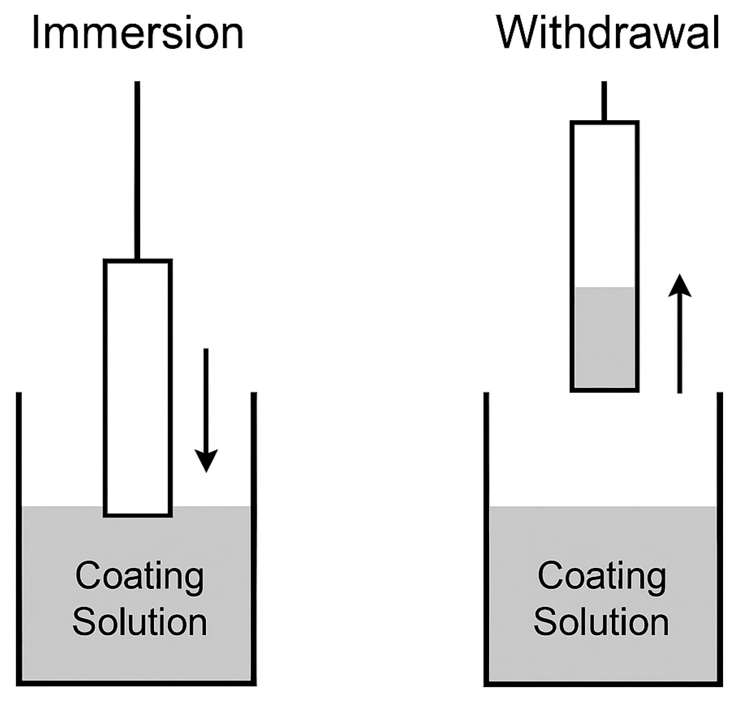
Figure 1. Dip-coating process. The downward arrow indicates the immersion stage, and the upward arrow indicates the withdrawal stage.
Automation 06 00075 g001
Figure 2. System concept.
Automation 06 00075 g002
Figure 3. Dip-Coater System. (a) External view with key dimensions, (b) Longitudinal section highlighting the main components, (c) Photograph of the assembled prototype.
Automation 06 00075 g003
Figure 4. System hardware block diagram.
Automation 06 00075 g004
Figure 5. PIC18F4550–A4988 wiring diagram.
Automation 06 00075 g005
Figure 6. Controller electronics. (a) PCB layout of the dip-coater controller, (b) assembled controller board integrated in the instrument.
Automation 06 00075 g006
Figure 7. Flowchart of the HMI.
Automation 06 00075 g007
Figure 8. GUI concept.
Automation 06 00075 g008
Figure 9. Triangular position profile.
Automation 06 00075 g009
Figure 10. Velocity for the triangular position profile.
Automation 06 00075 g010
Figure 11. Acceleration for the triangular position profile.
Automation 06 00075 g011
Figure 12. Trapezoidal position profile.
Automation 06 00075 g012
Figure 13. Velocity for the trapezoidal position profile.
Automation 06 00075 g013
Figure 14. Acceleration for the trapezoidal position profile.
Automation 06 00075 g014
Figure 15. GUI operation. (a) waiting for USB device, (b) connection confirmation and control enable, (c) homing to 0 mm, (d) manual jog down with live position feedback.
Automation 06 00075 g015
Figure 16. GUI-controlled dip-coating sequence. (a) system homed at 0 mm; (b) descent to the programmed immersion depth; (c) dwell at depth; (d) ascent and return to home.
Automation 06 00075 g016
Figure 17. Experimental position of the dip-coater (measured vs. simulated).
Automation 06 00075 g017
Figure 18. Experimental velocity of the dip-coater (measured vs. simulated).
Automation 06 00075 g018
Figure 19. Experimental acceleration of the dip-coater (measured vs. simulated).
Automation 06 00075 g019
Table 1. Comparison of representative low-cost dip-coater systems reported in the literature.
ReferenceControl ArchitectureKey Features
Dabirian et al. [22]Arduino + DC motorCombined spin/dip coater; programmable cycles
Yepuri & Addala [26]Arduino + linear actuatorHydrophobic TiO2 coatings; flame resistant
Bulut & Günel [27]Arduino + stepper motorHeating control; ZnO coatings
Rahman et al. [28]Microcontroller + calibration algorithmAuto-calibration, low error (<2%)
Bedoya et al. [29]Arduino + PWM controlStainless-steel frame; sol–gel coatings
Rauh et al. [30]3D printer (Ender-3) firmwareMulti-sample automation; high throughput
Adámek [23]PC + stepper driverEducational setup; 3D-printed parts
Dunlap et al. [31]Arduino + touchscreen GUISmartphone control; dust enclosure
Pérez et al. [32]Arduino + PID controlRevolver-type multilayer dip-coater
Ospina-Calderón et al. [33]Arduino Mega + HMISiO2 sol–gel coatings; tunable parameters
Castillo-Vilcatoma et al. [34]Arduino + recycled materialsEco-friendly build; ZnO and oxide films
This workPIC18F4550 + PC-hosted GUI (USB)Hybrid 3D-printed/aluminum design; USB control; modular, programmable automation
Table 2. Cost analysis.
ComponentCost (USD)
PLA10
Stepper motor10
Microcontroller10
PCB10
Electronic components10
Total50
Disclaimer/Publisher’s Note: The statements, opinions and data contained in all publications are solely those of the individual author(s) and contributor(s) and not of MDPI and/or the editor(s). MDPI and/or the editor(s) disclaim responsibility for any injury to people or property resulting from any ideas, methods, instructions or products referred to in the content.