Article

Integrating a Fast and Reliable Robotic Hooking System for Enhanced Stamping Press Processes in Smart Manufacturing

1
Department of Intelligent Commerce, National Kaohsiung University of Science and Technology, Kaohsiung 824005, Taiwan
2
Department of Engineering Science, National Cheng Kung University, Tainan 63300, Taiwan
*
Author to whom correspondence should be addressed.
Automation 2025, 6(4), 55; https://doi.org/10.3390/automation6040055 (registering DOI)
Submission received: 27 August 2025 / Revised: 1 October 2025 / Accepted: 3 October 2025 / Published: 12 October 2025
(This article belongs to the Section Robotics and Autonomous Systems)

Abstract

Facing the diversity of the market, the industry has to move towards Industry 4.0, and smart manufacturing based on cyber-physical systems is the only way to move towards Industry 4.0. However, there are two key concepts in Industry 4.0: cyber-physical systems (CPSs) and digital twins (DTs). In the paper, we propose a smart manufacturing system suitable for stamping press processes based on the CPS concept and use DT to establish a manufacturing-end robot guidance generation model. In the smart manufacturing system of stamping press processes, fog nodes are used to connect three major architectures, including device health diagnosis, manufacturing device, and material traceability. In addition, a special hook end point is designed, and its lightweight visual guidance generation model is established to improve the production efficiency of the manufacturing end in product manufacturing.

1. Introduction

Traditional automated manufacturing methods will not be sufficient to cope with the diverse and changing market demands. In order to solve the current situation, the industry uses new information technology to improve; this new technology includes the Internet of Things [1], artificial intelligence (AI), fifth-generation wireless systems (5G), and big data. In addition, we must consider the computing efficiency of big data transmission and analysis at the same time, so diversified network computing methods such as cloud computing [2] or edge computing [3] are proposed to optimize transmission and computing to make applications more flexible. Further, the advanced application of edge computing is to link physical and cyber elements through fog computing architecture. In fact, we can actually implement the above-mentioned technologies to the manufacturing end, which is the smart manufacturing that many experts currently advocate.
Completing smart manufacturing based on a series of technologies is an essential goal for the industry to move towards Industry 4.0 [4]. In addition to the IoT mentioned above, a more advanced approach is to connect cyber-physical systems of various technologies through smart connections [4]. However, according to the 5C architecture [5] of the entire CPS, it is a complex and cross-domain technology information system. CPSs can also be called a virtual–real integrated system, which is similar to the concept of digital twins (DTs) [6]. Its method mainly uses data from a large number of sensors to establish a connection between the virtual world and the real environment. Among them, the virtual world of the digital twin refers to the simulated environment that is the same as the real environment, while CPS refers to the network environment. Therefore, through the actual manufacturing hardware equipment, the information collected by a large number of sensors is integrated through the network. We apply this system to the industrial field, which can also be called a cyber-physical manufacturing system (CPMS). In addition, in [7], the author discusses the role of CPMSs in Industry 4.0 and the actual application timing at the manufacturing end. In order to make the connection between physical and cyber elements more intelligent and flexible and to reduce resources, a CPS-based IoT hub architecture is proposed in [5]. In summary, a CPMS is a high-level application of a CPS, which improves manufacturing efficiency through an efficient link between physical and cyber elements.
On the other hand, the manufacturing side of the factory must deal with high-mix and low-volume product orders. If product verification or mass production testing can be carried out in the virtual environment and the real environment, the production capacity of the product can be improved. However, according to the 5C [5] architecture of the entire CPS, it is a complex and cross-domain technology information system. Moreover, when it has to take into account the production mode, it will make the become a cyber-physical production system (CPPS) [8]. In [9], the authors propose an object detection method for small objects based on machine learning and create a data training set through a digital twin method to achieve personnel safety prevention in actual factories. In addition, they use the concept of DT and propose the use of dynamic aggregation technology to integrate production and products in [10]. Overall, the integration of CPSs and DTs will be a trend regardless of whether it is applied at the production end or the manufacturing end, and it is also an effective way for the industry to establish a smart factory in the face of a highly changing market.
In this paper, we mainly introduce smart manufacturing technology into the automation architecture designed and applied to metal processing production. According to the current situation, there are multiple manufacturing processes that often require manual transfer in the manufacture of metal products. However, if heavy metal products are encountered, the production capacity will be limited due to artificial physical fitness. Therefore, this paper takes the stamping press in the metal cold forging process as a subject and considers the problems of manufacturing and production to establish a system with the characteristics of both CPMSs and CPPSs. In addition, stamping press equipment is mainly used to manufacture products similar to wheel suspension [11], and the three devices covered by the overall process can be serially connected and communicate through the computing framework of the robot [12] to improve the overall manufacturing efficiency. Based on the whole automation architecture made of metal, in this paper, we propose an approach to solving the problem, the main contributions of which are as follows:
(1)
According to the wheel suspension process, the architecture of smart manufacturing is designed and includes the advantages of both CPMSs and CPPSs. In addition, the concept of the DT is considered, and the database J. Redmon generated by the virtual engine is combined with the database of real scenarios for machine learning training.
(2)
Development of a hook-type gripper based on the geometric structure of wheel suspension parts.
(3)
Design a generative model architecture that can be used universally for a parallel-jaw gripper and hook-type gripper and that can significantly improve performance.
This paper proposes a basic stamping press transfer automation architecture, including network computing architecture and robotic arm grasping method, and plans five chapters based on our proposed architecture. We discuss the relevant literature on network computing architecture and arm gripping in Section 2. Section 3 includes three parts—network computing architecture design, hook gripper, and robot system—and discusses a generative gripping point prediction model. Section 4 compares the experiments related to the grasping method of the robot arm, and the last section, Section 5, mainly summarizes the experimental results.

2. Related Work

In this paper, we use CPS-based smart manufacturing methods to improve the production capacity (diminished by labor shortages) of metal processing plants. In addition, according to the manufacturing characteristics of the factory, a machine learning-based arm gripping method is established on the physical side and a computing architecture corresponding to the cyber side is established.

2.1. Network Computing Architecture in Smart Manufacturing

In addition to focusing on efficiency at the manufacturing end, today’s factories must face high mix and low volumes of products; this is caused by supply and demand issues. The current situation has brought great pressure to the manufacturing side. Therefore, introducing CPSs into the production line to realize smart manufacturing will be an essential issue in the current trend of data transmission and calculation through different cyber architectures in CPSs.
This subsection will discuss network computing architecture on the cyber side. In fact, a network computing architecture like grid computing [13] was proposed when the software and hardware were not fully developed in the early days. Grid computing is an architecture that must integrate software and hardware computing resources through the network to improve computing capabilities. In addition, computing nodes are established through heterogeneous computing devices to form powerful computing devices in a resource-sharing manner in different geographic locations on the architecture. With the rapid development of software and hardware technology, cloud computing [14] architecture based on grid computing has been developed on network computing architecture to enable more flexible data transfer and complex analysis. The difference in computing architecture between grid computing and cloud computing is that the first is distributed and the latter is a service–client model. In addition, the three levels [2] of service proposed by the cloud service are the reasons why it can be widely used by users. Although cloud computing has solved most of the network computing problems in smart manufacturing, there are still some problems such as location awareness, high latency, and low support flexibility. Furthermore, the network computing architecture of fog computing [15] proposes to make up for the deficiencies of cloud computing, and its hierarchical architecture places computing resources as close as possible to terminal devices. The authors discuss how to apply fog computing to realize Industry 4.0 and the industrial Internet of Things in [15]. At present, fog computing has been widely used in systems that require high immediacy.

2.2. Robotic Grasping in Machine Learning

Automation is widely used in labor-intensive industrial manufacturing, and the introduction of robot arms in automation has further improved the efficiency and production capacity of the production line. Robotic arms are often used in picking, transferring, handling, or assembling in industrial manufacturing. However, these applications must confirm the position of the object through a sensor and then control the robot arm to move. In addition, on the physical side of the CPS architecture, the use of visual sensors combined with robotic arms and the integration of machine learning into cyber elements are the focus of this paper. Therefore, this section will discuss the relevant literature on the application of machine learning to solve the problem of robotic arms grasping different objects.
According to different robot grasping tasks, we can divide machine learning methods into model-based and model-free [16], and it is observed that the model-based architecture takes time to obtain a large amount of three-dimensional object information before training and cannot analyze unseen objects. Therefore, methods based on the model-free architecture have been proposed one after another, and the architecture of the method can be divided into discriminative models and generative models. However, the model architecture will be adjusted according to different tasks such as adding the evaluation network structure to improve the operation of objects [17] and determining the best gripping point for object transfer with the parallel-jaw gripper [18]. In addition, the basis of the generative model [18] is to generate the grip points established in the grasping rectangle with the parallel-jaw gripper structure. In the initial architecture [18], seven dimensions are used to represent the best grasping range, but the output of too many dimensions causes the model to be ineffective. Therefore, the new method [19] is simplified to five dimensions to represent and use the backbone network of deep learning to improve the accuracy of grasping. We benefit from the continuously proposed deep learning backbone network whereby the new robot grasping method [20,21] replaces ImageNet with ResNet through the backbone network to improve performance. However, the common problem of the aforementioned methods is high computational complexity, which not only results in longer computing time but also demonstrates accuracy that is not easy to improve. A new sampling method for grasp candidates is proposed, and its method is to calculate the grasp quality by generating pixel-level grasp points [22,23,24,25]. In addition, the front end of the parallel-jaw gripper defines keypoints and predicts the grip position based on the keypoints [26,27].
On the whole, robot grasping is very dependent on requirements, and the objects and situations applied in this paper make us have to consider computing performance and the processing of the unseen.

3. Robot Hooking and Network Computing Architecture for the Stamping Press Process

We will propose a series of robot solutions based on the problems of the actual stamping press process. (The stamping process investigated in this study is primarily based on cold stamping (or cold forging), in which a punch press applies pressure through a die to plastically deform the material for the purposes of forming, shearing, or bending. The core equipment used is the punch press, where the reciprocating motion of the slide transfers pressure to the die, thereby shaping the metal workpiece.) In addition, the method includes the gripper design of the robot, the optimal grasping position model of the robot, and the network computing architecture of the model.

3.1. Motivation

The manufacturing of wheel suspension parts must be carried out by a variety of stamping press equipment because of the complex structure, which uses the stamping machine as the power source and matches the die shape to shape the raw material into the body of the die by extrusion. However, before the wheel suspension parts enter the next process, they must be manually loaded and unloaded and sorted due to the distance between the equipment. In addition, the weight of the semi-finished product of the wheel suspension parts is about seven to eight kilograms, and the labor efficiency is not good. In summary, traditional manufacturing processes commonly encounter several issues, including the long distances between equipment, the heavy reliance on manual operations for feeding and classification, and the need to place materials into bins before transporting them to the inlets and outlets of subsequent processing equipment. To address these challenges, this thesis proposes improvements through automation and intelligent technologies. Specifically, automation is achieved by introducing robots to replace manual handling and operations, while intelligence is incorporated through the integration of smart vision recognition systems, thereby enhancing both the efficiency and accuracy of the overall manufacturing process.

3.2. Hook Structure at the Endpoint of the Robot

In fact, the design of the end of the robot arm used in industry is a very important issue, and the design of the end focuses on the geometric structure, rigidity, and surface roughness of the manipulated object. In the application of this paper, the robot arm is used to reduce the burden on the worker, and its task is to use the robot arm to grasp and move objects. We use a similar gripping rectangle-based robotic grasping method [20]. The robot grasping method based on the gripping rectangle can almost always use the parallel-jaw gripper with the traditional configuration, as shown in Figure 1a, in the selection of grippers. However, problems are easily caused when the jaw structure in Figure 1a is applied to the wheel suspension part of a specially shaped part, such as in Figure 1c. According to Figure 1d, slipping occurs easily in one of the gripping situations due to the weight of the object and the smooth surface at the gripping points on both sides. After analyzing different failure modes, we designed a new hook-type structure, as illustrated in Figure 1b. This design features a protrusion at the end of the hook, allowing it to engage with the circular slot at apex position A of the wheel suspension part in Figure 1b. By selecting point A as the clamping position, the hook-type structure not only secures the object effectively but also addresses issues of entanglement and prevents slipping on smooth surfaces.
It is also important to note that this thesis considers the limitations of the gripper design when applied to different types of objects. For instance, many everyday items such as shoes present irregular geometries rather than simple cylindrical, cubic, or spherical shapes. To accommodate such scenarios, part D of the proposed design incorporates a controllable-axis dynamic hooking mechanism. This enables flexible grasping and releasing, thereby enhancing the adaptability of the gripper to a broader range of objects.

3.3. Robot Hooking Method

This paper establishes a smart manufacturing framework for the stamping press process. Before the heat treatment of the stamping press process, the objects in the basket must be grasped by the robot to the iron frame. In addition, the system to guide robot grasping by vision is a common architecture, and many methods of vision-guided robot grasping have been proposed. At present, there are many methods of robot vision guidance and grasping based on deep learning, but we must consider computing performance and identification of unknown objects when constructing a deep learning architecture in practice. Therefore, this paper proposes a kind of high-performance generative network model and a new hooking structure to resolve the detection of robot grabbing rectangles. The robot grasping rectangle detection system is mainly established based on the grasping space of the parallel-jaw gripper as shown in Figure 1a. In addition, the learning objective is to consider the geometric structure of the object and find out the position that can be successfully grasped according to the gripping space of the parallel-jaw gripper. However, the grip effect of the parallel-jaw gripper on the wheel suspension part is not effective, so in this paper, we designed a hook-type gripper, as shown in Figure 1b, to solve the problems caused by actual use.
Although there is a big difference in appearance and structure, we designed the hooking rectangle for point A in Figure 1b to be similar to that in Figure 1a. Moreover, we considered the system performance and convergence to establish a representation method similar to the [27,28] hook rectangle; and we also considered the high-efficiency generative network model proposed in the paper. As shown in Figure 1e, the generated coordinate description can be expressed as the following formula:
G h = ( P h , Q h , W h , Φ h )
In (1), P h is based on the position of the Cartesian position at point D in Figure 1b. In fact, the position of point D captured by the other half of the virtual hook is the center point, which can be expressed as (x, y, z), and z is the camera depth information. Q h is the score of the successful hook. According to the direction of the z-axis, Φ h is the rotation angle of the object, and W h is the width of the object to be ticked. In addition, according to the object image, I = R n × h × w observed by the depth camera, and the internal parameters through the camera can be defined as:
g ~ h i = ( p ~ h i , q ~ h i , w ~ h i , ϕ ~ h i )
First, p is the center point (u, v) of the gripping position of the object observed through the camera in (2). Secondly, ϕ ~ h i and w ~ h i are the object’s rotation angle and the object’s width from the camera position, respectively. Finally, q ~ h i is the quality score of the hooking. In the actual scenario, the coordinates of the camera and the arm must be calibrated to plan the actual moving path of the arm, so we can define the coordinate conversion process as follows:
G h = T r i ( T c i ( g ~ h i ) )
In (3), T c i is used to convert the 2D image into the coordinates of the depth camera; then, the coordinates of the depth camera to the robot arm are calibrated through the T r i correction method. However, this paper uses an information embedding method, and we mainly embed the correct rectangular coordinates and range of the object’s hook into the image to generate the output image as shown in Figure 2. A new image space is defined according to such an information generation method:
G ~ h i = ( Q ~ h i , W ~ h i , Φ ~ h i ) R 1 × H × W
In (4), Q ~ h i , W ~ h i , a n d Φ ~ h i are three two-dimensional images whose content is embedded in the position coordinates of the hook grasp according to the value of Equation (2), including quality, width, and angle. In addition, the coordinates of the hook grasp center point are covered in the Q ~ h i image to solve the definition as follows:
g ~ h i * = m a x ( f g ( Q ~ h i ) )
In (5), we use the Gaussian function f g to find the coordinate with the highest grip quality of the Q ~ h i hook as the center point. In addition, we define its scope to include Q ~ h i as the quality of the hook grip [0, 1], Φ ~ h i as the rotation angle [ π 2 , π 2 ], and W ~ h i as the opening and closing width of the hook grip as [0, Wmax] in the embedded information. Among them, the part of Φ ~ h i is composed of two items of image information: cos( Φ ~ h i ) and sin( Φ ~ h i ). The definition is as follows:
Φ ~ h i = a r t a n s i n ( Φ ~ h i ) c o s ( Φ ~ h i ) / 2
Based on the hooking rotation angle of the end point, we define a continuous function in the range [ π 2 , π 2 ]. Therefore, in order to ensure that the angle is unique, an angle such as (6) is decomposed into two components. Previously, we defined the learning goal of hook grasping and then designed the learning framework f θ : I r g b d G ~ h i as shown in Figure 2. Through the learning model f θ , G ~ h i can be generated through the image I r g b d . According to the new hook grasp learning architecture proposed in this paper, f θ can be defined as follows:
f θ I r g b d = f u p . ( s i g m o d ( C 1 D k = 3 ( f b o t t l . ( f d o w n . ( I r g b d ) ) ) ) )
In (7), θ represents the weight in the learning model through the convolution operation as shown in Figure 2. The convolution operation includes the following: f u p . is the upsampling function, f b o t t l . is the bottleneck function, attention is carried out through the C1D function, and f u p . is upsampling for weight learning. It is worth mentioning that in part (7), compared with the attention in Figure 2, we use lightweight channel attention technology, and C1D is a one-dimensional convolutional neural network. According to (7), the lightweight convolutional neural network equation f θ must pass through the introduction of the loss function when learning how to generate the correct hook position. In this paper, we introduce the following loss function (8) to improve the stability of learning:
H u b e r δ = 1 = 1 2 G ~ h i G h i t , G ~ h i G h i l a b e l δ δ G ~ h i G h i t 1 2 δ , O . W .
In fact, (8) is a composite loss function called a Huber loss, which includes the advantages of mean square error and absolute mean square error. In this paper, a smaller δ value is selected to ensure learning stability.

3.4. Network Computing Architecture for Robot-Based Manufacturing of Wheel Suspension Parts

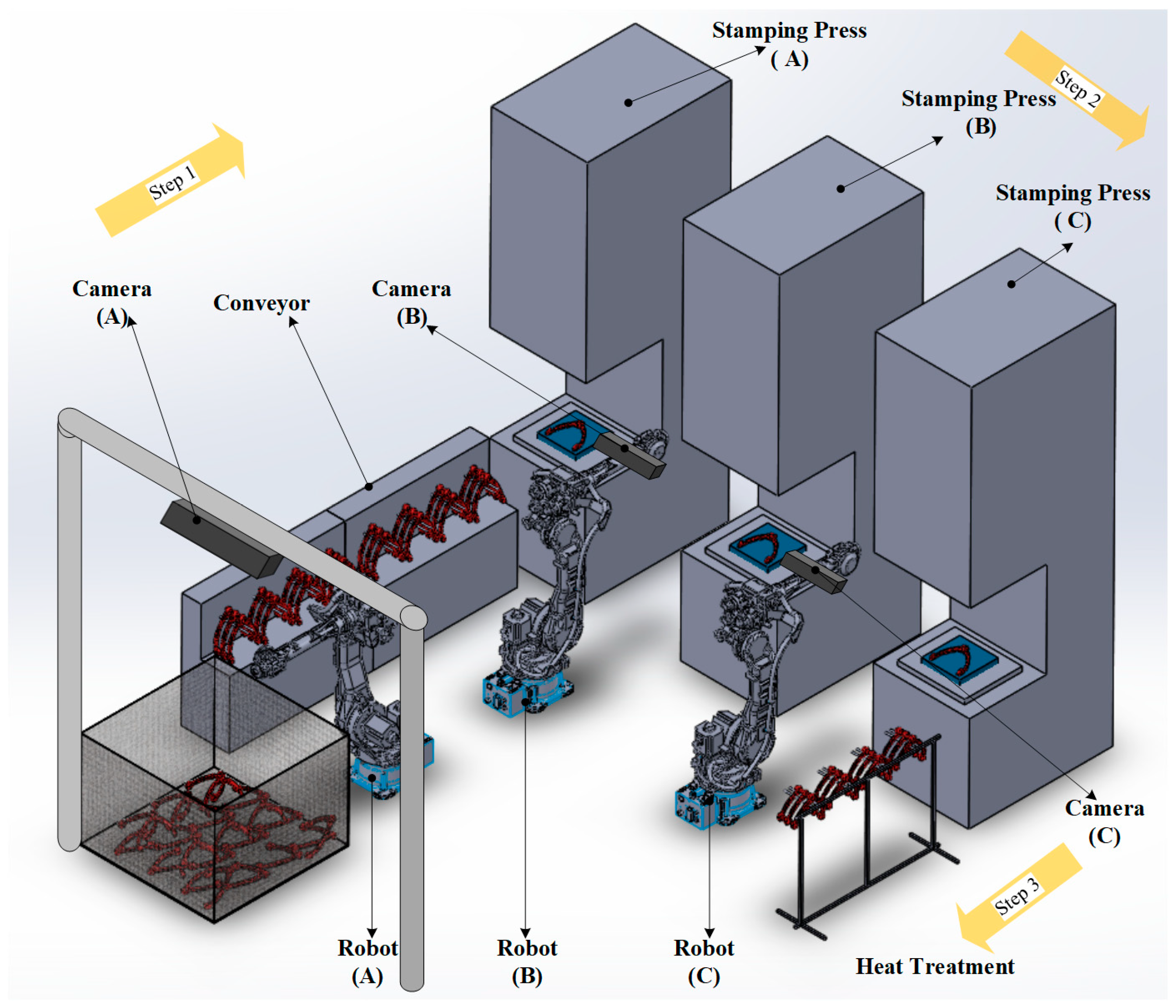
Our method not only utilizes the robot but also uses the camera with depth information to guide the robot, as shown in Figure 3. In Figure 3, we have designed a smart manufacturing method for processes with similar structures and divided it into three steps:
  • Step 1. This system can accurately take the objects out of the iron basket and place them on the conveyor, and the objects can be transferred to the stamping press through the conveyor.
  • Step 2. According to the transfer of the continuous stamping press, we use the eye-in-hand visual guidance method to move the objects to different mold stamping presses.
  • Step 3. Finally, the object is moved to the special bracket through the visual guidance of the robot eye in the hand and then heat-treated.
In Figure 4, we present a smart manufacturing framework, based on the stamping press, which integrates robot path planning, a visual position prediction model, stamping press quality sensing, and conveyor speed control. The framework is designed as a CPS (cyber-physical system) architecture that incorporates both manufacturing and production considerations. First, the manufacturing devices (MDs), device health (DH), and product traceability (PT) are constructed as resources of the physical node. Wireless sensors are primarily deployed in DH to predict product quality and monitor mold health, while the manufacturing core (MD) is controlled by a PLC and a master PC.
Second, to enhance overall manufacturing efficiency, the framework leverages fog computing, enabling data transmission through various communication methods from physical nodes. Data is transferred to small servers where internal software services—such as the robot picking model, quality analysis model, and scheduling optimization—are executed. Based on the computational results of each fog node, data is aggregated through cloud services and integrated with product cycle time. This enables the manufacturing status and production schedule to be communicated to users across different departments of the organization.
Moreover, the framework incorporates feedback mechanisms that span from raw materials to finished products, including device health diagnostics during the production process, thereby supporting optimal scheduling. Notably, the fog computing node functions as a cyber system, with the digital twin (DT) embedded within the machine learning model training framework of small- and medium-sized services in the fog environment. The primary role of the DT is to enhance the generalization capability of the model when deployed in real-world manufacturing scenarios.

4. Experiments

We have established a set of automatic transfer systems for multiple devices of stamping press equipment in our paper. This section will verify the entity and the database for the object transfer system composed of camera A and robot A in the core of the system as shown in Figure 4.

4.1. General Database Validation

4.1.1. Dataset and Evaluation Metric

Among different databases, this paper selects those of Cornell [18] and Jacquard [29], which are verified by many papers that discuss grasping by robots. However, the evaluation index will use the definition of [30] for the end gripper, including the rotation angle of the generated rectangle, the marked rectangle less than 30°, and the overlap ratio of the generated rectangle and the marked rectangle:
J ( r p , r t ) r p r t r p r t > 1 4

4.1.2. Learning Network Architecture Difference Analysis

The novel machine learning structure improves learning rate and the initialization of the adjusted model. Therefore, adding batch normalization [31] between layers is proposed. The principle of batch normalization is mainly to normalize the weight of each batch so that its weight is kept within a certain range and that the slope in this area and the efficiency of model training will be reduced. However, the improvement is still limited by the stability of the low gradient descent, and the gradient is not easy to model during training. If the model does not improve, the gradient will disappear. However, our paper considers hardware that reduces the learning rate because we were concerned about the initialization of the performance by increasing the number of layers; therefore, our method attempts to improve performance and uses smaller batches for training. Currently, the batch normalization effect is not significant, so we consider a new weight normalization method referred to as group normalization [32]. The difference between group normalization and batch normalization is that the former normalizes through channels, and the latter normalizes the number of samples.
Since this architecture uses a batch size of 8, we can see from Table 1 that the performance of group normalization on different databases is relatively good. The correct rate in Table 1 is obtained based on the evaluation indicators of the two items in the evaluation index section, and the calculation method must be determined when all the indicators are established to be successful. In addition, we consider the stable sampling of the results and calculate the ratio of success to failure after sampling k groups of samples.

4.1.3. Validation Based on Different Datasets

Cornell and Jacquard’s datasets are often cited in experiments for analysis and comparison in the issue of robot grasping accuracy based on grasping rectangles. In fact, the content of the two datasets was explained in the first subsection.
First, Table 2 is utilized to verify the effect of the Cornell dataset and uses untrained samples for testing after random sampling of the dataset. In addition, the experimental results in Table 2 demonstrate that the application of the model architecture illustrated in Figure 2 not only achieves high accuracy but also maintains stable performance. It is worth noting that beyond showing better results compared with other methods, this experiment is also designed to evaluate the generalization capability of the model. Specifically, in the image-wise setting, the entire dataset is randomly shuffled and divided into training and testing sets, which evaluates the model’s ability to predict the optimal grasping positions for objects it has already encountered. In contrast, the object-wise setting partitions the dataset by object instances, where the objects in the testing set do not appear in the training set, thereby assessing the model’s performance on entirely unseen objects. Secondly, according to the same model architecture, the accuracy of different methods through the large Jacquard dataset also has better performance, as shown in Table 3. Table 4 primarily investigates the impact of different combinations of color space information on the feature weight of optimal grasping regions. The experimental results indicate that utilizing the RGB-D combination on the Cornell dataset yields superior predictions of optimal grasping positions. Since the Cornell dataset is a real image, and the Jacquard dataset is a virtual image, according to the results, it is known that the difference in color between the real image and the virtual image will affect the model identification Finally, the actual inference results in the Cornell and Jacquard datasets are shown in Figure 5.

4.1.4. Computing Performance of Different Devices

The framework of the hooking model proposed in this paper is mainly applied to the key transfer system of the stamping press in Figure 3, which is mainly composed of camera A and robot A. Since the system applied by the hooking model is the starting point of the entire cold satin process, it is crucial to the efficiency of the entire process. Therefore, this section will discuss the hardware operation of the fog node in Figure 4. First, this paper discusses the essential floating-point operations (FLOPs) capabilities of some similar models as shown in Table 5. After actual verification, it can be found that the computing performance can be greatly improved on the 2080Ti hardware, but the performance of higher-end hardware is limited. Finally, this section considers the experimental results and applies 2080Ti hardware to the fog nodes of the network computing architecture in Figure 2 to accelerate the model’s computing.

4.1.5. Clamping Category Classification Based on Cornell Dataset Regional Features

This section establishes a robot hook category recognition method based on the model architecture illustrated in Figure 2 and a series of subsequent processes. Specifically, it focuses on predicting the graspable pixel regions of different objects using the proposed architecture. By overlapping multiple graspable pixel regions, the largest merged area is obtained, and its centroid is used as the representative point. Among the candidate centroids, the one closest to the object is selected as the actual grasping position of the claw. Accordingly, the key objective of this experiment is to evaluate whether the multiple predicted graspable pixel regions of a single object adequately cover the target object and to assess the accuracy of the predictions. After considering the geometric appearance of the objects in the Cornell dataset, we divide the categories of the dataset into forty categories. In addition to geometric appearance, this section will establish the method through the following process:
  • The category is judged according to the similar geometric appearance and hooking position in the Cornell dataset. The 240 objects in the Cornell dataset can be divided into 40 categories.
  • In Figure 6, we encode the class of the hooking point.
  • We update the model architecture part of Figure 6 to the following output:
    f ( s ) j = e s j j = 1 C e s j j = 0 ~ C
  • By embedding the category into the hook area and obtaining the quality, angle, width, and classes of the hook area at the same time during inference, we are able to sort the number of categories in the hook area according to Equation (11) and find the category with the largest number of occurrences; this category is identified as follows:
    C b = Max C 1 n , C 2 n , C 3 n , C c n ,   c = 1 ~ 40 , n = 0 ~ n 1
In (11), C b is denoted as the possible class, and C 1 n to C c n are denoted as class candidates covered in the hook area. We use the evaluation database of the Cornell dataset for category judgment. Our paper assesses the performance of various methods in object recognition by constructing the confusion matrix presented in Figure 7, with the corresponding recognition rate statistics summarized in Table 6. The comparative results demonstrate that the proposed model achieves superior performance within the regional pixel feature recognition framework.

4.2. Real-Scenario Verification

In Figure 3, we illustrate the planned smart manufacturing process of a punch press in metal cold forging. In this setup, camera A and robot A are responsible for the loading and unloading of wheel suspension parts. The scenario depicted in Figure 3 reflects a real-world environment, where the robot retrieves a wheel suspension part from an iron basket and places it onto a conveyor. Since the positions of the objects in the iron basket are not fixed, the loading and unloading operations must be guided by vision. This paper not only proposes a novel robot grasping point model learning architecture but also introduces a newly designed hook-type gripper.
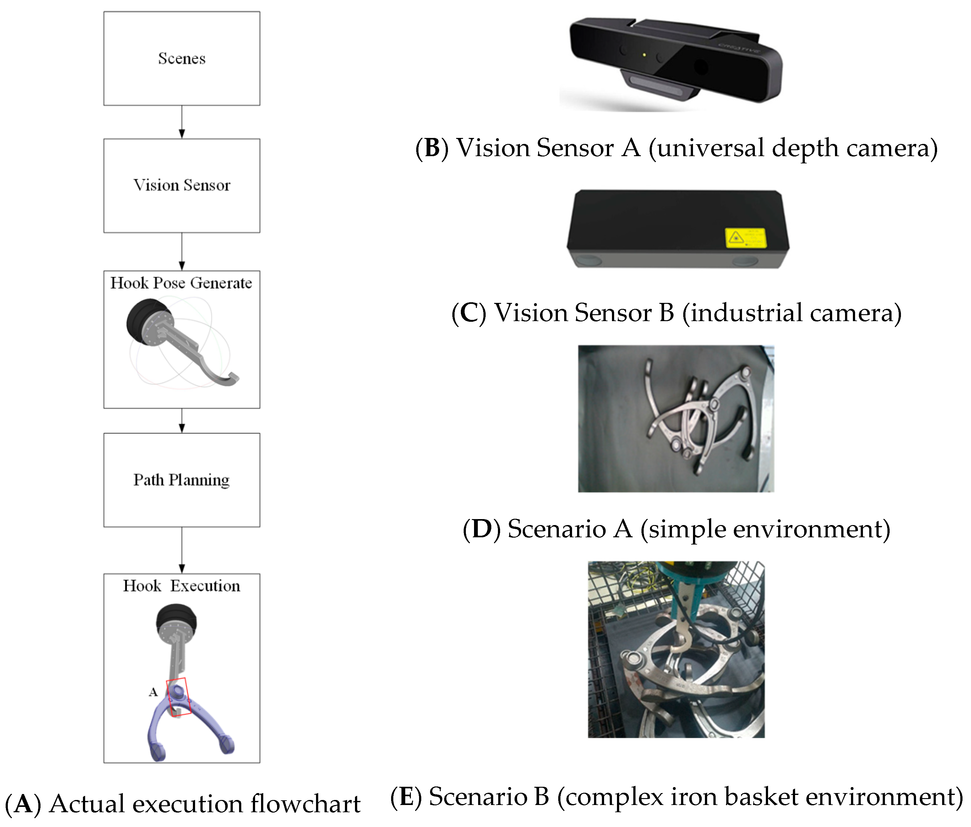
In this section, practical tests are conducted for the newly designed hook-type gripper in combination with the vision-based method. First, experiments are carried out following the system flowchart shown in Figure 8A, using different vision sensors and environments. The choice of test environment is determined by the working range of each vision sensor. Specifically, Vision Sensor A has a working distance of 0.5–1.2 m, allowing objects to be placed freely on the platform, while Vision Sensor B has a working distance of 8–20 m and is thus tested in the iron basket scenario.
As illustrated in Figure 9, the system performs inference using the vision sensor in conjunction with the proposed model architecture. Subsequently, as shown in Figure 10, the robot executes the workflow described in Figure 8. After calibration between the depth camera and the robot’s end-effector, the object is captured by the depth sensor, and the grasping position is predicted and transformed into an actual hooking location. The robot arm is then assigned a start and end point, and through automatic path planning, it successfully reaches hooking point A or B to secure the object. Finally, this study also evaluates the model’s performance across different scenarios and with alternative vision sensors. As shown in Table 7, the proposed model demonstrates robust stability in the hooking task.

5. Conclusions

The stamping press in the metal cold forging process can produce specially shaped metal parts and is widely used in different industrial fields. This paper proposes a smart manufacturing framework for the stamping press process based on the wheel suspension part, which includes the machine learning model of the robot’s visual gripping system and a new type of end gripping structure. In addition, according to the key factors of process and production, the robot system developed and designed in this paper is covered through CPSs.
However, the robot gripping system proposed in this paper must be equipped with a new hook-type gripper which can overcome the entanglement problem of specially shaped structural objects. In the model architecture, we use color information to integrate depth information as input and build a new generative model architecture to deduce the coordinates of the robot’s hook. The new generative model modifies the feature extraction module to make the model lighter and has stable output results, whether in a general dataset or a natural environment. It not only establishes an innovative robot gripper and coordinate deduction model but also constructs a suitable network computing architecture to make it a system with low latency, high security, low resource consumption, and high performance.
Finally, according to the experimental results, we achieved 98.8% and 96.13% performance in the Cornell and Jacquard datasets, respectively. In addition, the FLOPs only have 10.1 parameters, and each frame can be completed in 12 msec in terms of performance.

Author Contributions

Conceptualization, Y.-C.C. and C.-F.L.; methodology, Y.-C.C.; software, Y.-C.C.; validation, F.-Y.C., Y.-C.C. and C.-F.L.; formal analysis, Y.-C.C.; investigation, Y.-C.C. and F.-Y.C.; resources, C.-F.L.; data curation, Y.-C.C.; writing—original draft preparation, Y.-C.C.; writing—review and editing, Y.-C.C. and C.-F.L.; visualization, Y.-C.C. and F.-Y.C.; supervision, C.-F.L.; project administration, Y.-C.C.; funding acquisition, C.-F.L. All authors have read and agreed to the published version of the manuscript.

Funding

This research received no external funding.

Data Availability Statement

The data that support the findings of this study are available from the corresponding author upon reasonable request.

Conflicts of Interest

The authors declare no conflict of interest.

References

  1. Ashton, K. That ‘Internet of Things’ thing. RFID J. 2009, 22, 97–114. [Google Scholar]
  2. Chellappa, R. Intermediaries in cloud-computing: A new computing paradigm. In Proceedings of the INFORMS Annual Meeting, Dallas, TX, USA, 26–29 October 1997. [Google Scholar]
  3. Lopez, P.G.; Montresor, A.; Epema, D.; Datta, A.; Higashino, T.; Iamnitchi, A.; Barcellos, M.; Felber, P.; Riviere, E. Edge-centric Computing: Vision and Challenges. ACM SIGCOMM Comput. Commun. Rev. 2015, 45, 37–42. [Google Scholar] [CrossRef]
  4. Xue, Y.; Pan, J.; Geng, Y.; Yang, Z.; Liu, M.; Deng, R. Real-Time Intrusion Detection Based on Decision Fusion in Industrial Control Systems. IEEE Trans. Ind. Cyber Phys. Syst. 2024, 2, 143–153. [Google Scholar] [CrossRef]
  5. Tao, F.; Cheng, J.; Qi, Q. IIHub: An industrial Internet-of-Things hub toward smart manufacturing based on cyber-physical system. IEEE Trans. Ind. Inform. 2018, 14, 2271–2280. [Google Scholar] [CrossRef]
  6. Liu, W.; Xu, X.; Qi, L.; Zhou, X.; Yan, H.; Xia, X.; Dou, W. Digital Twin-Assisted Edge Service Caching for Consumer Electronics Manufacturing. IEEE Trans. Consum. Electron. 2024, 70, 3141–3151. [Google Scholar] [CrossRef]
  7. Zhang, J.; Tian, J.; Luo, H.; Wu, S.; Yin, S.; Kaynak, O. Prognostics for the Sustainability of Industrial Cyber-Physical Systems: From an Artificial Intelligence Perspective. IEEE Trans. Ind. Cyber Phys. Syst. 2024, 2, 495–507. [Google Scholar] [CrossRef]
  8. Xia, C.; Wang, R.; Jin, X.; Xu, C.; Li, D.; Zeng, P. Deterministic Network–Computation–Manufacturing Interaction Mechanism for AI-Driven Cyber–Physical Production Systems. IEEE Internet Things J. 2024, 11, 18852–18868. [Google Scholar] [CrossRef]
  9. Zhou, X.; Xu, X.; Liang, W.; Zeng, Z.; Shimizu, S.; Yang, L.T.; Jin, Q. Intelligent small object detection for digital twin in smart manufacturing with industrial cyber-physical systems. IEEE Trans. Ind. Inform. 2022, 18, 1377–1386. [Google Scholar] [CrossRef]
  10. Fraccaroli, E.; Vinco, S. Modeling Cyber-Physical Production Systems with System C-AMS. IEEE Trans. Comput. 2023, 72, 2039–2051. [Google Scholar] [CrossRef]
  11. Pochyly, A.; Kubela, T.; Singule, V.; Cihak, P. 3D vision systems for industrial bin-picking applications. In Proceedings of the 15th International Conference MECHATRONIKA, Prague, Czech Republic, 5–7 December 2012. [Google Scholar]
  12. Zhang, K.; Shi, Y.; Karnouskos, S.; Sauter, T.; Fang, H.; Colombo, A.W. Advancements in Industrial Cyber-Physical Systems: An Overview and Perspectives. IEEE Trans. Ind. Inform. 2023, 19, 716–729. [Google Scholar] [CrossRef]
  13. Sharma, S.K.; Chaurasia, A.; Sharma, V.S.; Chowdhary, C.L.; Basheer, S. GEMM, a Genetic Engineering-Based Mutual Model for Resource Allocation of Grid Computing. IEEE Access 2023, 11, 128537–128548. [Google Scholar] [CrossRef]
  14. Gad, A.G.; Houssein, E.H.; Zhou, M.; Suganthan, P.N.; Wazery, Y.M. Damping-Assisted Evolutionary Swarm Intelligence for Industrial IoT Task Scheduling in Cloud Computing. IEEE Internet Things J. 2024, 11, 1698–1710. [Google Scholar] [CrossRef]
  15. Teoh, Y.K.; Gill, S.S.; Parlikad, A.K. IoT and Fog-Computing-Based Predictive Maintenance Model for Effective Asset Management in Industry 4.0 Using Machine Learning. IEEE Internet Things J. 2023, 10, 2087–2094. [Google Scholar] [CrossRef]
  16. Sundermeyer, M.; Mousavian, A.; Triebel, R.; Fox, D. Contact-GraspNet: Efficient 6-DoF Grasp Generation in Cluttered Scenes. In Proceedings of the IEEE International Conference on Robotics and Automation (ICRA), Xian, China, 30 May–5 June 2021. [Google Scholar]
  17. Duffhauss, F.; Koch, S.; Ziesche, H.; Vien, N.A.; Neumann, G. SyMFM6D: Symmetry-Aware Multi-Directional Fusion for Multi-View 6D Object Pose Estimation. IEEE Robot. Autom. Lett. 2023, 8, 5315–5322. [Google Scholar] [CrossRef]
  18. Jiang, Y.; Moseson, S.; Saxena, A. Efficient grasping from rgbd images: Learning using a new rectangle representation. In Proceedings of the International Conference on Robotics and Automation (ICRA), Shanghai, China, 9–13 May 2011. [Google Scholar]
  19. Redmon, J.; Angelova, A. Real-time grasp detection using convolutional neural networks. In Proceedings of the International Conference on Robotics and Automation (ICRA), Seattle, WA, USA, 26–30 May 2015; Available online: https://www.kaggle.com/datasets/oneoneliu/cornell-grasp (accessed on 1 November 2023).
  20. Yu, S.; Zhai, D.H.; Xia, Y.; Wu, H.; Liao, J. SE-ResUNet: A Novel Robotic Grasp Detection Method. IEEE Robot. Autom. Lett. 2022, 7, 5238–5245. [Google Scholar] [CrossRef]
  21. Chen, L.; Niu, M.; Yang, J.; Qian, Y.; Li, Z.; Wang, K. Robotic Grasp Detection Using Structure Prior Attention and Multiscale Features. IEEE Trans. Syst. Man Cybern. Syst. 2024, 54, 7039–7053. [Google Scholar] [CrossRef]
  22. Cao, H.; Chen, G.; Li, Z.; Feng, Q.; Lin, J.; Knoll, A. Efficient Grasp Detection Network with Gaussian-Based Grasp Representation for Robotic Manipulation. IEEE/ASME Trans. Mechatron. 2023, 28, 1384–1394. [Google Scholar] [CrossRef]
  23. Cheng, H.; Wang, Y.; Meng, M.Q.H. Anchor-Based Multi-Scale Deep Grasp Pose Detector with Encoded Angle Regression. IEEE Trans. Autom. Sci. Eng. 2024, 21, 3130–3140. [Google Scholar] [CrossRef]
  24. Tong, L.; Song, K.; Tian, H.; Man, Y.; Yan, Y.; Meng, Q. A Novel RGB-D Cross-Background Robot Grasp Detection Dataset and Background-Adaptive Grasping Network. IEEE Trans. Instrum. Meas. 2024, 73, 9511615. [Google Scholar] [CrossRef]
  25. Zuo, G.; Shen, Z.; Yu, S.; Luo, Y.; Zhao, M. HBGNet: Robotic Grasp Detection Using a Hybrid Network. IEEE Trans. Instrum. Meas. 2025, 74, 2503109. [Google Scholar] [CrossRef]
  26. Xu, R.; Chu, F.J.; Vela, P.A. GKNet: Grasp keypoint network for grasp candidates detection. Int. J. Robot. Res. 2022, 41, 361–389. [Google Scholar] [CrossRef]
  27. Liu, D.; Feng, X. A Real-Time Grasp Detection Network Based on Multi-scale RGB-D Fusion. In Proceedings of the International Joint Conference on Neural Networks (IJCNN), Yokohama, Japan, 30 June–5 July 2024. [Google Scholar]
  28. Kumra, S.; Kanan, C. Robotic grasp detection using deep convolutional neural networks. In Proceedings of the International Conference on Intelligent Robots and Systems (IROS), Vancouver, BC, Canada, 24–28 September 2017. [Google Scholar]
  29. Depierre, A.; Dellandrea, E.; Chen, L. Jacquard: A large scale dataset for robotic grasp detection. In Proceedings of the International Conference on Intelligent Robots and Systems (IROS), Madrid, Spain, 1–5 October 2018. [Google Scholar]
  30. Kumra, S.; Joshi, S.; Sahin, F. Antipodal robotic grasping using generative residual convolutional neural network. In Proceedings of the International Conference on Intelligent Robots and Systems (IROS), Las Vegas, NV, USA, 24 October 2020–24 January 2021. [Google Scholar]
  31. Ioffe, S.; Szegedy, C. Batch normalization: Accelerating deep network training by reducing internal covariate shift. arXiv 2015, arXiv:1502.03167. [Google Scholar] [CrossRef]
  32. Wu, Y.; He, K. Group normalization. In Proceedings of the European Conference on Computer Vision, Munich, Germany, 8–14 September 2018. [Google Scholar]
  33. Lenz, I.; Lee, H.; Saxena, A. Deep learning for detecting robotic grasps. Int. J. Robot. Res. 2015, 34, 705–724. [Google Scholar] [CrossRef]
  34. Chu, F.J.; Xu, R.; Vela, P.A. Real-World Multi-object, Multi-grasp Detection. IEEE Robot. Autom. Lett. 2018, 3, 3355–3362. [Google Scholar] [CrossRef]
  35. Zhou, X.; Lan, X.; Zhang, H.; Tian, Z.; Zhang, Y.; Zheng, N. Fully convolutional grasp detection network with oriented anchor box. In Proceedings of the International Conference on Intelligent Robots and Systems (IROS), Madrid, Spain, 1–5 October 2018. [Google Scholar]
  36. Zhou, Z.; Zhu, X.; Cao, Q. AAGDN: Attention-Augmented Grasp Detection Network Based on Coordinate Attention and Effective Feature Fusion Method. IEEE Robot. Autom. Lett. 2023, 8, 3462–3469. [Google Scholar] [CrossRef]
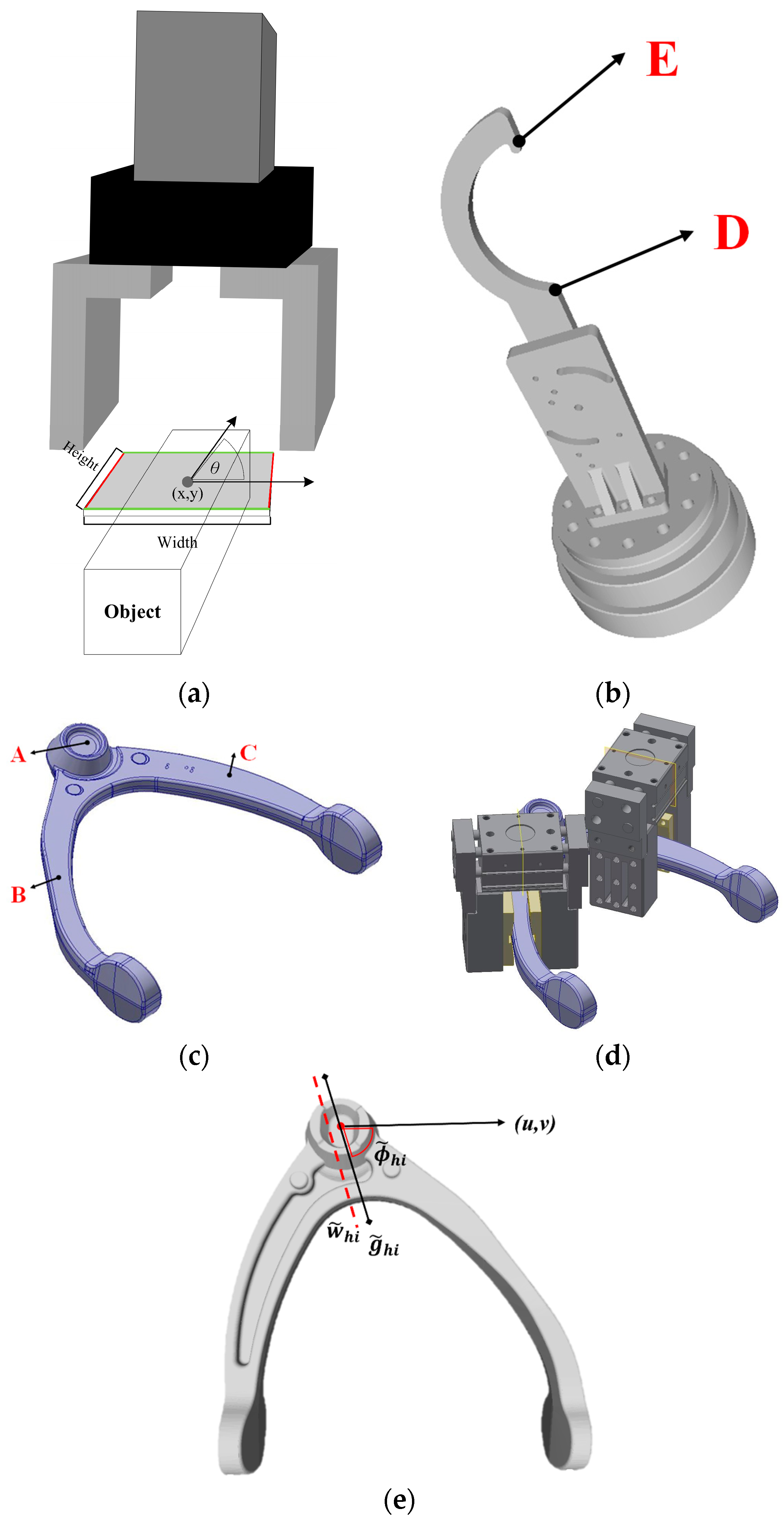
Figure 1. Grasping structure and coordinate definition of robot endpoint. (a) Parallel-jaw gripper at the endpoint of traditional robots, (b) new robot endpoint hook structure, (c) wheel suspension part, (d) the robot grabs the wheel suspension part with a parallel-jaw gripper, (e) coordinate definition of new robot hook structure.
Automation 06 00055 g001
Figure 2. Hook position prediction model architecture.
Automation 06 00055 g002
Figure 3. Stamping press automatic production system based on intelligent manufacturing.
Automation 06 00055 g003
Figure 4. Network Computing Architecture of Fog Computing.
Automation 06 00055 g004
Figure 5. The actual output of the model on different datasets. In the result section of the figure, the orange box indicates the extractable region, and its center point corresponds to the target position D shown in Figure 1b. In addition, the numerical ranges of the color mappings for Quality, Angle, and Width are described in Figure 2.
Automation 06 00055 g005
Figure 6. Hook rectangular category encoding.
Automation 06 00055 g006
Figure 7. For different methods applied to object grasp recognition in the Cornell dataset, confusion matrices have been constructed and compared to illustrate the differences in classification and recognition performance among the approaches. (A) Our method. (B) S. Kumra [28]. (C) S. Yu [20]. (D) R. Xu [26].
Automation 06 00055 g007
Figure 8. Hardware and processes tested in actual scenarios.
Automation 06 00055 g008
Figure 9. The experimental results of different hardware and scenarios.
Automation 06 00055 g009
Figure 10. The results of the actual execution in the factory.
Automation 06 00055 g010
Table 1. Differences in model architecture in different datasets. Efficient channel attention (ECA), accuracy (AAC.), normalization (Nor.).
DatasetNor. MethodAcc. (%)
JacquardBatch nor.95.60
Group nor.96.13
CornellBatch nor.97.75
Group nor.98.8
Table 2. Analysis of different methods based on Cornell dataset.
MethodAcc. (%)Speed
(msec)
Year
Image-WiseObject-Wise
Y. Jiang [18] 60.558.350002011
I. Lenz [33] 73.575.613502015
J. Redmon [19]8887.1762015
S. Kumra [28]89.288.91032017
F. J. Chu [34] 9689.11322018
X. Zhou [35]97.796.61172018
S. Kumra [20]97.796.6202021
R. Xu [26]96.996.847.672021
S. Yu [20] 98.297.1252022
Z. Zhou [36]99.398.8182023
H. Cao [22] 97.8-62023
L. Chen [21]99.298.4282024
L. Tong [24]97.896.7-2024
D. Liu [27]95.294.462024
Our Method98.894.38122025
Table 3. Analysis of different methods based on Jacquard dataset.
MethodAcc. (%)Speed (msec)Year
A. Depierre [29]74.214.562018
X. Zhou [35]91.81172018
F. J. Chu [34]95.081322018
S. Kumra t [28]94.6202021
R. Xu [26]98.3923.262021
S. Yu [20] 95.7252022
Z. Zhou [36]96.2182023
H. Cao [22]95.562023
L. Chen [21]96.1282024
H. Cheng [23]92.3-2024
L. Tong [24]94.6332024
Our Method96.13122025
Table 4. Accounting for differences in color space in different methods.
DatasetColor MapMethodAccuracy (%)
JacquardRGB-DS. Kumra [28]94.6
R. Xu [26]88.78
S. Yu [20]95.7
Our Method92.48
RGDS. Kumra [28]95.48
R. Xu [26]98.39
S. Yu [20]94.5
Our Method96.13
CornellRGB-DS. Kumra [28]97.7
R. Xu [26]96.63
S. Yu [20]98.2
Our Method98.8
RGDS. Kumra [28]93.26
R. Xu [26]96.9
S. Yu [20]94.38
Our Method96.63
Table 5. Model inference time on different hardware times (Msec/Frame).
Method @FLOPs(G)S. Kumra [34]
@22
S. Yu [20]
@18
R. Xu [26]
@11.9
Our Method
@10.1
Devices @CUDA
Intel CPU@0(i7-9700F) from U.S.A17616561375
AverMedia Jetson Xavier NX@384 from T.W47925348
Dell 1050Ti @768 from T.W38703945
Nvida TITANV@5120 from U.S.A9223218
ASUS 2080Ti@4352 from T.W8152212
GIGABYTE 3070Ti@6144 from T.W611189
ZOTAC 4070Ti@7680 from H.K37114
Table 6. Classification results according to regional features of different methods.
MethodOur MethodS. Kumra [34]S. Yu [20]R. Xu [26]
Accuracy (%)83798269
Table 7. Hooking success rate (%) of different methods in actual scenarios.
Success/TotalScenario AScenario B
Method
GR-ConvNet [30]84 (21/25)96(24/25)
SE-ResUNet [20]80 (20/25)96 (24/25)
GKNet [26]92 (23/25)68 (17/25)
Our method100 (25/25)92 (23/25)
Disclaimer/Publisher’s Note: The statements, opinions and data contained in all publications are solely those of the individual author(s) and contributor(s) and not of MDPI and/or the editor(s). MDPI and/or the editor(s) disclaim responsibility for any injury to people or property resulting from any ideas, methods, instructions or products referred to in the content.