1. Introduction
Autonomous vehicle technology is advancing rapidly, driven by efforts from both the automotive industry and academic institutions. These developments aim to enhance safety, efficiency, and driver convenience [
1]. According to the Society of Automotive Engineers (SAE) [
1], automation levels range from Level 0 (no automation) to Level 5 (full automation), where no human intervention is needed. However, most current systems operate below Level 5 and still require human input in complex or failure-prone scenarios [
2,
3]—such as navigating through narrow lanes or reacting to unexpected obstacles. In situations where the driver is incapacitated or the vehicle is uncrewed, a remote operation system becomes essential. Despite their value, remote systems face challenges—primarily related to latency over communication networks. Hence, a reliable control transition framework, supported by an efficient alert system and robust communication infrastructure, is critical for enabling a seamless shift between autonomous and remote-control modes in emergency or failure situations.
The transformation of conventional vehicles into autonomous platforms necessitates integration with core systems like steering, throttle, and braking through electronically controlled actuators. A common method for achieving this is through x-by-wire technology [
4], which replaces mechanical control linkages with electronic signal-based systems. This study focuses on the design, implementation, and evaluation of an autonomous electric vehicle capable of transitioning between autonomous and remote-control modes using 5G communication. Building on earlier research [
5,
6], a 14-seat electric golf cart was modified by integrating actuators in the steering, acceleration, and braking systems—collectively referred to as the vehicle’s low-level control systems [
7]. For steering, electric power steering (EPS) was interfaced with a custom controller to simulate torque signals. The braking system used a brushless DC motor to actuate the pedal via cable and pulley, delivering responsive control for speeds up to approximately 8.33 m/s (approximately 30 km/h). The acceleration system emulated throttle signals to regulate the electric motor directly, completing the core control triad.
Further developments in similar research projects have used varied configurations of control systems and actuators. For example, some studies have implemented external actuators on the steering column, employing sensors and motorized torque feedback systems [
8]. Others have upgraded small electric vehicles, such as the Toyota COMS, to Level 3 automation using satellite-based GNSS for high-level path planning [
9]. In comparison, this study introduces a unique braking system utilizing a hydraulic mechanism driven by a DC motor to directly pressurize brake lines, resulting in smoother braking without pedal displacement—a marked improvement over previous rod-actuated designs. The remote operation concept, as defined by teleoperation [
10], allows a human operator to control a vehicle from a distant location without direct visual contact. A typical teleoperation interface includes visual feeds, sensor data, and input devices like a steering wheel and pedals. Interfaces vary from direct video-based control to multimodal systems with sensor fusion, supervisory systems for semi-autonomous guidance, and experimental methods like neural control using bio-signals.
In remote driving scenarios, effective control depends on a triad: the teleoperator, communication link, and operator interface. Prior studies using vehicles like the Audi Q7 have demonstrated the practicality of teleoperation using multiple cameras and sensor arrays configured to meet regulatory standards [
11]. Cameras provided 180° frontal views and additional angles for side and rear visibility, with real-time video streaming at 25 fps. Communication used 3G and 4G networks, and latency was evaluated using round trip time (RTT) metrics. The control station mirrored a real driving setup with multiple monitors and input devices. Despite latencies up to 500 ms, remote driving remained feasible at moderate speeds. However, high latency has been shown to significantly affect performance, particularly in complex tasks or systems with high degrees of freedom. For example, research on underwater camera platforms demonstrated that delays increase total operation time [
12]. Some systems mitigate this by buffering commands during high latency and executing them when latency drops, although minimal operator input combined with autonomous fallback systems remains the most effective strategy for maintaining safety and performance.
Modern remote driving applications require ultra-low latency and high-bandwidth communication, conditions met by 5G technology [
13]. The fifth-generation cellular network (5G), standardized under IMT-2020, supports various communication needs: mMTC for dense device environments, eMBB for high-throughput applications, and URLLC for ultra-reliable, low-latency tasks—ideal for autonomous vehicles. Current 5G deployments primarily use sub-6 GHz bands, which balance coverage and performance, while mmWave bands offer higher speeds but limited range and penetration [
14,
15]. There are two modes in which 5G architecture can be implemented: non-standalone (NSA), built on existing 4G infrastructure, and standalone (SA), which uses native 5G architecture for superior latency, speed, and data handling [
16,
17]. Complementing the communication layer, Autoware [
18,
19,
20] is an open-source autonomous driving platform running on the Robot Operating System (ROS). It consolidates sensing, computing, planning, and control modules into a cohesive framework. Autoware ingests sensor data—LiDAR, GNSS, radar, and cameras—for localization, object detection, and mission and motion planning. The resulting velocity commands are sent to the vehicle’s low-level controllers to execute safe and intelligent driving maneuvers. This software’s modular design and extensive support tools streamline development, making it a cornerstone in academic and industrial autonomous vehicle projects.
While earlier efforts have retrofitted electric platforms for autonomy [
6,
7], or demonstrated public trials of autonomous golf carts [
9], these systems lack the capability to switch between autonomous and remote operation. Furthermore, they do not account for network latency variations during teleoperation—a crucial factor for ensuring safety in degraded 5G environments. Prior studies on teleoperation interfaces [
11,
12,
13] and empirical 5G performance [
14,
16,
18] highlight the importance of robust fallback strategies, yet no previous work has implemented a latency-aware transition logic coupled with a physical emergency braking response.
Compared to existing solutions that rely on uninterrupted connectivity or only partially support remote fallback, this system uniquely integrates real-time network feedback into control logic and employs hardware-level emergency handling. This addresses a critical gap in current platforms operating over public 5G networks.
This research proposes a real-world dual-mode driving platform that (1) enables seamless transitions between autonomous and 5G-based remote operation, (2) incorporates real-time latency monitoring using ROS tools, and (3) triggers a hardware-based emergency braking mechanism when latency exceeds safety thresholds. Unlike existing studies, our implementation is tested in real-world 5G sub-6 GHz conditions with full hardware integration and live network feedback. These contributions position the system as a practical solution to edge-case safety in next-generation mobility platforms.
2. Literature Review on 5G Teleoperation and Fallback Systems for Autonomous Vehicles
Despite significant progress, most autonomous vehicles (AVs) remain at SAE Levels 2–4 and continue to rely on human oversight in unpredictable or edge-case scenarios [
2,
21]. This dependence has driven the adoption of teleoperation—where trained human operators intervene remotely through high-speed communication networks—as a vital fallback mechanism, especially for Level 4 vehicles. Recent field trials conducted in Ref. [
22] demonstrated that remote drivers were able to resolve complex real-world traffic situations such as construction detours. However, the study also identified practical challenges related to operator readiness, latency compensation, and legal/regulatory frameworks that remain unresolved.
Reliable teleoperation is underpinned by fast and stable network connections. The 5G-Blueprint project [
23] showed that sub-6 GHz 5G deployments can deliver round-trip times (RTTs) between 40 and 60 ms under normal conditions, although handover events caused occasional latency spikes up to 300 ms. In another trial, Ref. [
24] demonstrated average glass-to-glass (G2G) latency of 202 ms and RTT of 47 ms in a Kia Soul EV pilot, revealing that even modest latency can significantly degrade response accuracy. At a speed of approximately 8.33 m/s (equivalent to 30 km/h), for example, the added braking distance from a 200 ms delay can exceed one meter, undermining safe operation [
24,
25].
To mitigate these latency issues, researchers have developed predictive human–machine interface (HMI) technologies. Ref. [
25] proposed a future-image generation method based on GAN–ConvLSTM models which can anticipate driving scenes and reduce operator lag under high-latency conditions. Similarly, Ref. [
26] described the implementation of a Kalman filter-based predictive display system that masked 0.5 s delays, enabling smoother control in curved road scenarios. These systems enhance perceived responsiveness but also introduce new challenges related to system calibration and user trust.
Interface design itself remains a crucial element in effective teleoperation. In a public transport context, the authors of Ref. [
27] developed a multi-camera dashboard UI, enhancing spatial awareness and decision-making during remote operation. Complementing this, the authors of Ref. [
28] compared traditional car-like control layouts to optimized HMI alternatives, concluding that task-specific layouts can reduce cognitive workload, albeit sometimes at the expense of maneuver efficiency.
Nevertheless, teleoperation remains vulnerable to severe network disruptions. Latencies exceeding 500 ms can render remote control impractical or even unsafe [
24,
29,
30,
31,
32]. For this reason, onboard fallback strategies such as minimal risk maneuvers (MRMs) are essential. Ref. [
33] proposed a fallback strategy based on differential braking and linear quadratic regulation (LQR) that can bring a vehicle to a safe stop within its lane even on curved roads. Standards bodies like ISO and NIST reinforce these needs by promoting robust architectural paradigms—particularly the doer/checker/fallback model, which ensures layered redundancy in safety-critical systems [
30].
Recent trends in integration further enhance teleoperation and fallback viability. On the communication front, Ref. [
34] modeled 5G NR radio-layer latency under ultra-reliable low-latency communication (URLLC) conditions, while Ref. [
35] extended this to a cross-layer latency framework tailored for V2X and remote driving. These models are vital for anticipating and bounding delay profiles in real-time applications.
In positioning, urban navigation can benefit from fusing 5G mmWave signals with inertial navigation systems (INSs). Refs. [
36,
37] demonstrated that UKF-based fusion techniques could achieve <30 cm positioning accuracy over 97% of the time in dense environments like downtown Toronto, making them promising for teleoperated vehicles in GPS-degraded areas.
In terms of software architecture, NIST’s framework [
38] outlines modular implementations of the doer/checker/fallback concept with voter-based logic and time-triggered scheduling to ensure consistent behavior under fault conditions. Meanwhile, The Autonomous project [
39] presents industry-ready architecture patterns that leverage control channel redundancy and failover priorities to facilitate safe transitions between automated and fallback modes.
In summary, the current literature presents a rich and evolving foundation encompassing 5G-based communication systems, predictive control interfaces, advanced localization, and resilient safety architectures. While significant progress has been made, especially in experimental validation and cross-layer modeling, further work is required to holistically integrate these components into scalable, real-world-ready teleoperation platforms.
3. Designs and Developments
3.1. Overall Designs
This research presents the design and development of a control transition system that enables seamless switching between autonomous and remote operation modes on a modified electric golf cart. The system allows real-time control transitions based on environmental conditions or system performance. When the control mode experiences either a malfunction or its performance limits, the transition system ensures continued vehicle control by allowing intervention through an alternate mode. This dual-mode functionality is essential for ensuring operational safety, especially in unpredictable or constrained environments.
To support this functionality, a malfunction surveillance system was developed to monitor both the autonomous and remote subsystems. It identifies anomalies and classifies them into various diagnostic categories. Upon detecting an abnormal event, the system alerts the control station, prompting the operator to take corrective action. Two critical scenarios were addressed: one where the vehicle, while in autonomous mode, detects a stationary obstacle and halts; if the obstacle remains beyond a defined threshold, the system alerts the operator to switch to remote control (
Figure 1a). The other occurs during remote operation, where excessive network latency prompts the system to recommend switching back to autonomous mode for safer control (
Figure 1b).
Communication between the prototype vehicle and the control station is achieved through 5G wireless networking dedicated remote-control modules installed on both ends. This high speed allows the operator to respond effectively; a low-latency connection ensures reliable command transmission and real-time video feedback. The control station is equipped with a display monitor, vehicle control interface, latency indicators, and a mode-switch button, providing full situational awareness and control flexibility. The hardware and software integration between the vehicle and the control station supports both manual and automated control transitions.
The operational flow of the control transition system is summarized in
Figure 2. Manual mode switching can be initiated at any time by the operator using the designated button at the control station. However, in critical situations detected by the malfunction surveillance system, the system autonomously overrides the current mode and activates emergency braking to stop the vehicle. This immediate response mechanism ensures safety when neither control mode can operate reliably. Then, the control station alerts the operator, who can assess and resolve the situation by switching to the appropriate mode. This bidirectional transition framework provides a robust, adaptive control strategy for autonomous vehicle operation under real-world constraints.
The diagram in
Figure 2 outlines the interactions between sensing, planning, control, and fallback modules, as well as communication interfaces across the vehicle and control center.
The proposed system integrates both autonomous and teleoperation modes within a unified architecture. On the vehicle side, sensor modules—including LiDAR, GNSS, and cameras—feed data to Autoware’s perception and localization nodes, running on the onboard ROS framework. These data streams support mission planning and trajectory generation. A controller node then issues actuation commands to low-level interfaces: throttle, steering, and braking systems—each modified with electronic control modules. In parallel, a 5G communication module transmits compressed video streams and sensor metadata to the control center while receiving remote driving commands.
On the control center side, a teleoperation interface replicates vehicle controls using a physical steering wheel and pedals, processed through a USB-to-CAN interface. Incoming sensor and camera data are visualized in real time to assist remote operation. ROS tools enable real-time latency monitoring. If the measured delay surpasses safety thresholds, the fallback controller overrides teleoperation inputs and initiates automated braking via a dedicated actuator. All components are synchronized through ROS nodes and topics across the communication channel.
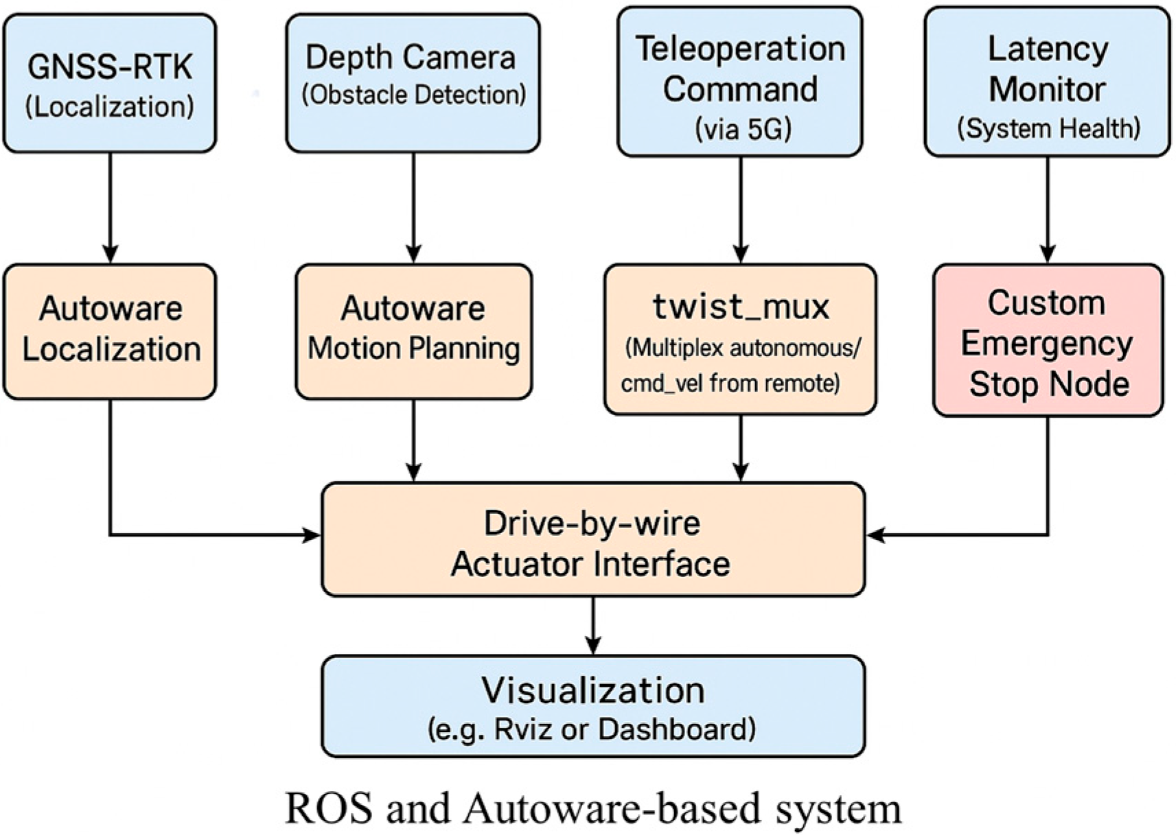
ROS and Autoware System Architecture
This study implements a dual-mode driving platform capable of switching between autonomous and teleoperated control. The system architecture is built on the Robot Operating System (ROS) framework, with core autonomous functionalities handled by Autoware modules, such as localization, perception, planning, and control. In parallel, a 5G-based teleoperation channel enables remote intervention. Real-time network latency is continuously monitored, and when communication delay exceeds predefined thresholds, a fallback mechanism engages autonomous braking to maintain safety.
Figure 3 shows the ROS/Autoware system-level architecture used in the prototype. The architecture integrates sensor data acquisition (e.g., LiDAR, camera), localization, path planning, and control nodes. A custom teleoperation module handles remote command reception, while a fallback controller ensures safe maneuvering under degraded network conditions. Communication across modules is managed via ROS topics and services.
3.2. Vehicles
The prototype vehicle developed for this study is based on the EVT Plus D 6s electric multi-purpose golf cart, modified to incorporate electronic steering control via a steer-by-wire system. Since the base model lacks an electric power steering (EPS) system, a DC motor (24 V, 350 W, 450 rpm) was selected to provide sufficient torque—estimated at 17.6 Nm with a safety factor of two—for stationary steering. The torque was amplified using a belt gear system, tripling the motor output. To monitor the steering position, a 10 kΩ, 10-turn potentiometer was installed via custom gear teeth to avoid over-rotation and damage. The steering system is controlled using an Arduino board, which sends PWM signals to a high-capacity H-bridge DC motor driver capable of supporting up to 200 A and voltages of 12–36 V. A PID controller ensures fast and accurate adjustments through continuous feedback.
Because electric golf carts lack direct speed feedback, two measurement systems were developed. The first uses the internal speed sensor of the CURTIS 1268 controller, which outputs a frequency signal proportional to the vehicle’s speed. This frequency was calibrated using 2D LiDAR to correlate the measured displacement with speed values. The second method involves a wheel-mounted incremental rotary encoder with a resolution of 60 pulses per revolution, connected via a 6 mm flexible cable. This dual-sensor setup provides reliable and redundant speed tracking under various conditions. For throttle control, voltage readings from the potentiometer ranged from 0 to 4.4 V, correlating directly with speed. A 12-bit MCP4922 DAC was used to regulate this voltage via SPI, with effective values ranging from 0 to 3600 out of a maximum of 4095.
For braking, to avoid direct control of hydraulic pressure, a 400 W servo motor provides torque, which is converted into linear force using a five-lead ball screw to actuate a custom hydraulic pump. The motor operates in torque control mode, responding to inputs between −10 V and +10 V. Since the control board provides only 0–5 V, an op-amp circuit was designed to convert this signal appropriately. The integrated control unit, including comprising steering, speed, and braking systems, is compactly housed beneath the vehicle’s second-row seat. To support onboard electronics, a compact lightweight LiFePO4 battery with an active balancing battery management system (BMS) was selected. This setup improves efficiency and safety while reducing weight, as detailed in
Figure 4.
The electrical system shown in
Figure 4 powers all vehicle control modules and sensors. It distributes regulated voltage from the main battery to subsystems such as the steering motor, brake actuator, and throttle emulator, which are central to both autonomous and teleoperated control. Additionally, power is supplied to the on-board computing units running ROS and Autoware, the 5G modem for real-time communication, and peripherals such as LiDAR and GNSS receivers. This system ensures stable operation of all components involved in low- and high-level control logic.
For safety, the vehicle includes two emergency stop modes. The first, accessible from either the vehicle or a control station, halts automation and fully engages the brake until a complete stop is reached. The second mode, operable only via a button on the vehicle, cuts off power to all accessories except the computer and communication modules. To facilitate environmental sensing, a Velodyne VLP-16 3D LiDAR scanner is mounted on the vehicle’s roof. Emitting 16 laser beams in a ±15° vertical range while rotating 360° horizontally, the LiDAR calculates object distance using time of flight (TOF). Positioned 2.5 m high, it ensures full forward visibility and avoids roof interference. A three-axis adjustable mount enables tuning for varied tasks. For geolocation, the U-blox C099-F9P GNSS module captures real-time satellite signals to generate precise latitude and longitude data, enhancing localization and 3D mapping accuracy.
3.3. Remote Cockpit and 5G Communication System
Four 720p video cameras were strategically installed around the prototype vehicle to capture the surrounding environment and transmit real-time footage to a control station. The video feeds are displayed across three monitors, providing the remote driver with a wide-angle and immersive visual field. This setup enhances situational awareness and creates a driving experience closely resembling that of operating a conventional vehicle. The control interface at the station includes a Logitech G29 Driving Force system, which replicates standard car controls such as the steering wheel, horn, headlights, turn signals, accelerator, brake pedal, and gear shift. Additional equipment, including a remote emergency stop button, mode selection switches (for toggling between autonomous and remote control), a mode status indicator, and a real-time signal latency LED, are arranged ergonomically around the driver’s seat to mirror a typical vehicle interior and ensure operational familiarity as shown in
Figure 5.
The 5G communication module used in this study operated in sub-6GHz NSA mode on a commercial network. During field trials, the system achieved an average round-trip latency of approximately 110 ms, with worst-case spikes up to ~317 ms under network load. These values were measured using ROS-based timestamping tools and are within the tolerable range for low-speed remote driving scenarios.
Communication between the control station and the prototype vehicle is facilitated by a 5G sub-6GHz non-standalone (NSA) cellular network. Signal transmission begins with a computer sending data via a twisted pair cable to a customer premises equipment (CPE) unit, which relays it to an active antenna unit (AAU) at the base station. From there, data travel via fiberoptic cable to the core network, which routes it to the destination system using the same sequence, as illustrated in
Figure 6. Commands transmitted from the control station to the vehicle include inputs for steering, acceleration, and braking and require high reliability and accuracy. To ensure this, the system utilizes the transmission control protocol (TCP), known for its error-checking and data integrity mechanisms. Conversely, video signals sent from the vehicle to the control station are larger in size and more time-sensitive. Therefore, the user datagram protocol (UDP) is employed to prioritize speed, despite its reduced reliability and potential for occasional data loss. This dual-protocol strategy ensures efficient and dependable communication tailored to the specific needs of control and feedback functions.
The control system designed in this research enables seamless switching between autonomous and remote-control modes by the operator at the control station during real-time operation. To clearly indicate the current mode, a status light is used: green denotes remote-control mode, yellow indicates autonomous mode, and red signals an emergency. A red light is triggered autonomously when the system detects conditions such as excessive communication delay during remote control or prolonged obstacle presence during autonomous driving. When this occurs, the system prompts the controller to take immediate action by confirming a mode change. An additional LED indicator, located near the steering wheel, displays real-time latency information. Each LED color corresponds to a specific delay range, allowing the controller to quickly assess communication performance. This indicator is integrated into the same control unit that houses the mode switch, emergency stop button, and system status light.
The data exchange architecture between the prototype vehicle and control station is modular and organized using the Robot Operating System (ROS), which serves as the central middleware. All data from sensors, microcontrollers, and external software are received, processed, and routed through ROS topics that enable communication across system components. The communication between the prototype vehicle and control station is conducted over a 5G wireless network, ensuring rapid and reliable transmission. Modules like Logitech signal transmission, mode switching, and latency monitoring manage their respective data streams and interface with ROS for seamless integration. These components ensure that the system remains adaptable, responsive, and safe across various operational conditions.
To enhance safety and control flexibility, the system includes five operating modes: (1) vehicle emergency mode, activated by the onboard surveillance system in response to high latency, obstacle detection, or manual emergency activation; (2) vehicle manual mode, which disengages all electric actuators to allow onboard human control; (3) cockpit emergency mode, triggered only by the remote operator; (4) autonomous mode, where the vehicle operates independently; and (5) remote control mode, enabling teleoperation via the control station. The transition between these modes is managed by the control mode switcher module, which makes decisions based on real-time diagnostics. For example, if the system detects high latency during autonomous operation, it prevents switching to remote-control mode until latency levels fall within safe limits. This constraint ensures that control is not transferred under unsafe conditions, reinforcing operational safety. The system’s design prioritizes responsiveness and robustness, providing both manual and automated fail-safes to handle abnormal events efficiently.
4. Experimental Setup
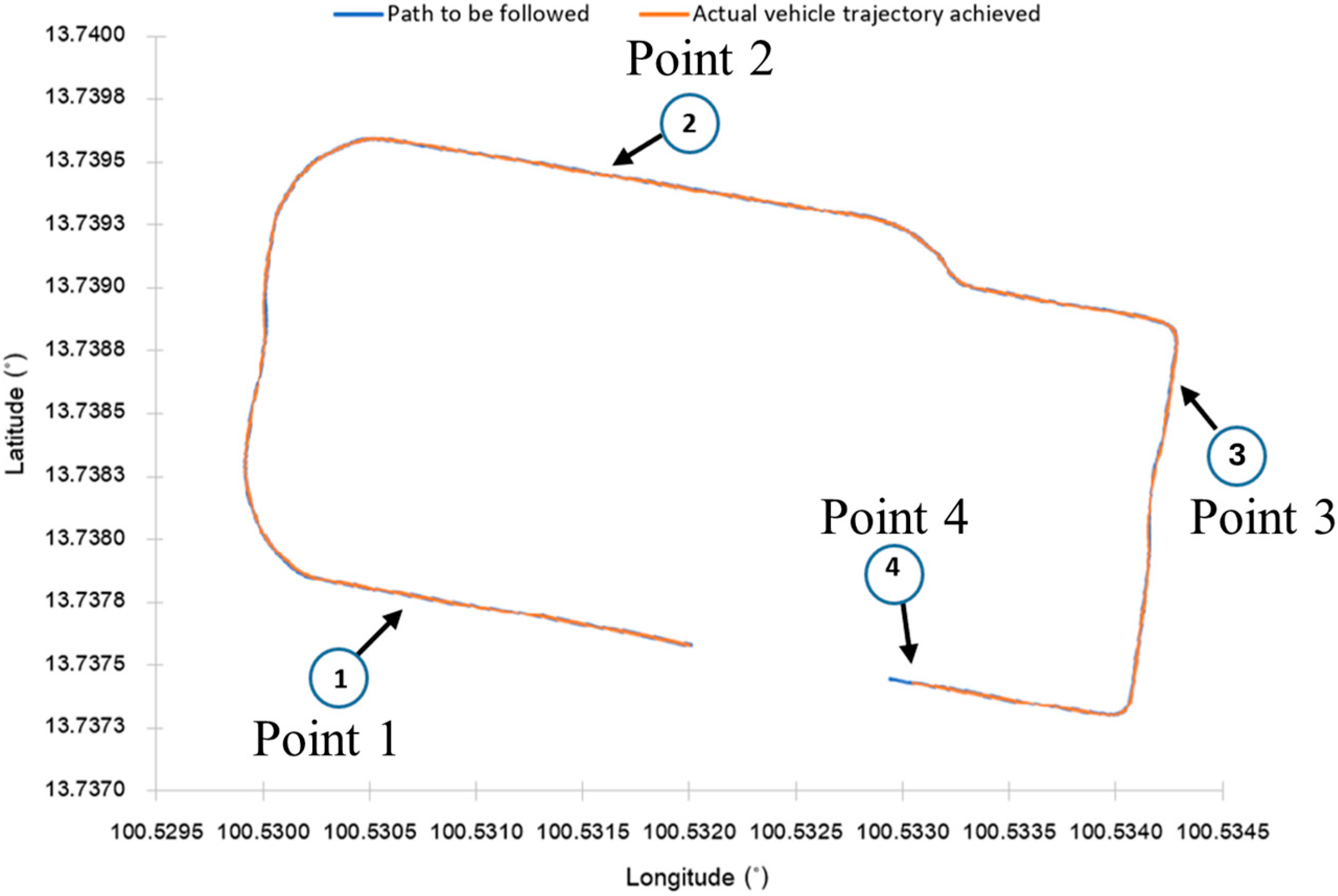
Once the prototype vehicle was developed, testing of the control transition system between autonomous driving and remote operation was conducted on the Chulalongkorn University campus. The test route followed a one-way, clockwise loop (
Figure 7a), with the vehicle’s speed limited to approximately 4.17 m/s (approximately 15 km/h). During autonomous operation, the vehicle followed a pre-recorded path, maintaining proximity to the left lane to provide a visual reference for the remote controller. This consistency helped the operator align the vehicle using lane markings visible on the control station’s monitor. The system was tested under two main scenarios (
Figure 7b). In the first, the vehicle encountered a stationary obstacle while in autonomous mode, prompting it to brake to a full stop. If the obstacle remained beyond a predefined duration, the system triggered a red warning light at the control station, prompting the operator to take control via remote-control mode. In the second scenario, if high latency was detected during remote operation, the red light signaled the need to switch back to autonomous mode for safety.
The test involved four designated control transition points along the route. Throughout the test, the latency indicator light enabled the remote operator to monitor real-time communication delays and switch modes or activate the emergency stop as needed. To evaluate system responsiveness, the research compared the linear deviation between the actual path and the recorded reference path. It also measured the response of the steering and speed systems relative to control inputs from the Logitech G29 controller and the Autoware autonomous driving platform. These responses were mapped with corresponding GPS coordinates and latency values using a U-blox FED-F9P GNSS module. Round trip time (RTT) latency between the vehicle and the control station was measured using a custom Python 3.7 script. Time synchronization between the two systems was maintained via the Chronyd method, which leverages the Network Time Protocol (NTP) to ensure both computers operate with precise and consistent timing. This setup ensured accurate latency measurement and reliable performance evaluation of the transition control system.
The test procedure begins with the vehicle operating under remote control from the starting point to point 1. During this segment, a simulated signal delay of 500 milliseconds is introduced by the controller at the control station. Although the actual measured latency remains within acceptable limits, the system is designed to enter emergency mode if the delay exceeds the threshold. Upon detecting this hypothetical delay, the vehicle autonomously brakes to a stop, triggering the red status lights on both the vehicle and control station to notify the operator. The latency indicator LED, located to the left of the steering wheel, also turns red, confirming the simulated delay exceeds 500 milliseconds. The controller then presses the mode switch button to transition the system from remote to autonomous control. Once the mode is switched, the status light changes to orange, and the vehicle resumes movement in autonomous mode.
The vehicle continues autonomously to point 2, where an obstacle simulated as a human is in front of the vehicle. Upon detecting the obstruction, the vehicle brakes to a stop and starts a 20 s countdown. If the obstacle remains beyond this time, the system autonomously enters emergency mode. Red status lights are activated on both the vehicle and control station. The controller observes the LED latency indicator, which is green (indicating a delay of less than 100 milliseconds), confirming safe communication for remote operation. Next, the controller switches the system to remote-control mode, and the status light changes to green. The remote operator resumes driving to the next point.
From point 2 to point 3, the vehicle remains in remote-control mode. At point 3, the same 500-millisecond delay simulation is introduced again. As with point 1, the system enters emergency mode once the delay threshold is detected. The vehicle autonomously brakes to a full stop, and the red status lights activate on both the test vehicle and the control station. The latency indicator LED shows red again, confirming the high simulated delay. The controller switches from remote to autonomous mode, changing the status light to orange, and the vehicle continues autonomously.
The vehicle proceeds in autonomous mode to point 4, where another obstacle simulated as a human is positioned in the vehicle’s path. Once detected, the vehicle brakes and initiates the 20 s countdown. If the obstacle is not cleared in time, the system again enters emergency mode, activating the red status lights. The controller verifies that the latency indicator shows green (delay below the safety threshold), and switches to remote control. After the status light turns green, the controller resumes manual operation of the vehicle.
Throughout this test sequence, the system’s transition logic, latency-based emergency detection, and manual override functionalities are validated under both simulated and real-world conditions
5. Results and Discussions
The delay values recorded during testing, correlated with the vehicle’s latitude and longitude, are illustrated in
Figure 8. LED color coding was used to represent different delay levels at the control station. The average and maximum actual delay values were 109.7 ms and 316.65 ms, respectively. A simulated delay exceeding 500 ms, marked in red, was intentionally introduced to trigger the emergency stop mechanism at designated safe locations (points 1 and 3) for system testing. This simulated delay was excluded from the analysis of real latency values. The autonomous vehicle followed a predefined waypoint reference path, created by logging the actual on-road positions.
Figure 9 compares the real path of the autonomous and remote-control systems to the reference path, showing successful path adherence. Linear deviation from the reference path was analyzed across four segments. In the initial remote-control segment (start to point 1), shown in
Figure 10a, average and maximum deviations were 0.25 m and 0.41 m. The straight nature of this section aided control accuracy. From points 1 to 2, under autonomous control, the route featured curves and intersections, leading to a higher maximum deviation of 0.88 m, as displayed in
Figure 10b. The segment from points 2 to 3 (
Figure 10c), also remote-controlled, showed the lowest average deviation at 0.19 m. Lastly, from points 3 to 4, autonomous control produced an average and maximum deviation of 0.34 m and 0.83 m, as shown in
Figure 10d. Overall, remote control yielded slightly lower average deviations, but autonomous mode exhibited larger peak deviations—up to twice as high.
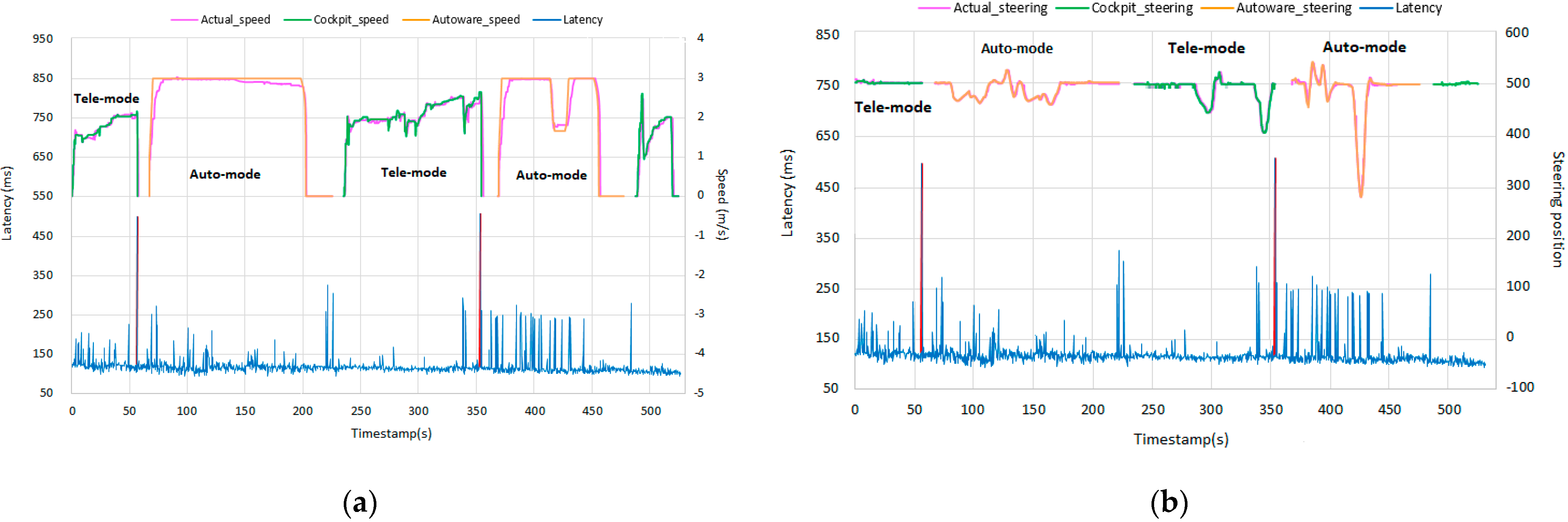
Speed and steering data from the test vehicle’s sensors were compared to commands issued by Autoware and a Logitech G29 controller, along with latency measurements for each phase of the control transition test, as shown in
Figure 11a,b. During the first phase (start to point 1) under remote control, minimum and average latencies were 89.24 ms and 115.69 ms, respectively, with a maximum of 217.11 ms. Despite intermittent spikes above 200 ms, control performance remained stable. Upon detecting the simulated 500 ms delay at point 1, the emergency monitoring system activated the braking mechanism, stopping the vehicle and entering emergency mode. When switched to autonomous control, the vehicle continued from points 1 to 2, experiencing average and minimum latencies of 110.18 ms and 83.68 ms and a peak of 316.65 ms. However, this delay did not affect vehicle control. At point 2, an obstacle prompted Autoware to command a stop. After 20 s on standby, the system entered emergency mode. Remote control resumed for points 2 to 3 with an average latency of 106.49 ms and a maximum of 284.8 ms. A simulated high delay was detected at point 3, and triggered emergency mode like at point 1. Autonomous mode resumed from points 3 to 4, with an average, minimum, and maximum latency of 110.39, 89.01, and 266.29 ms, respectively. Upon detecting an obstacle at point 4, the vehicle decelerated and stopped before entering emergency mode. In the final phase (point 4 to the end), the vehicle returned to remote control, showing a stable latency profile with maximum latency at 120.56 ms—lower than previous remote-control phases.
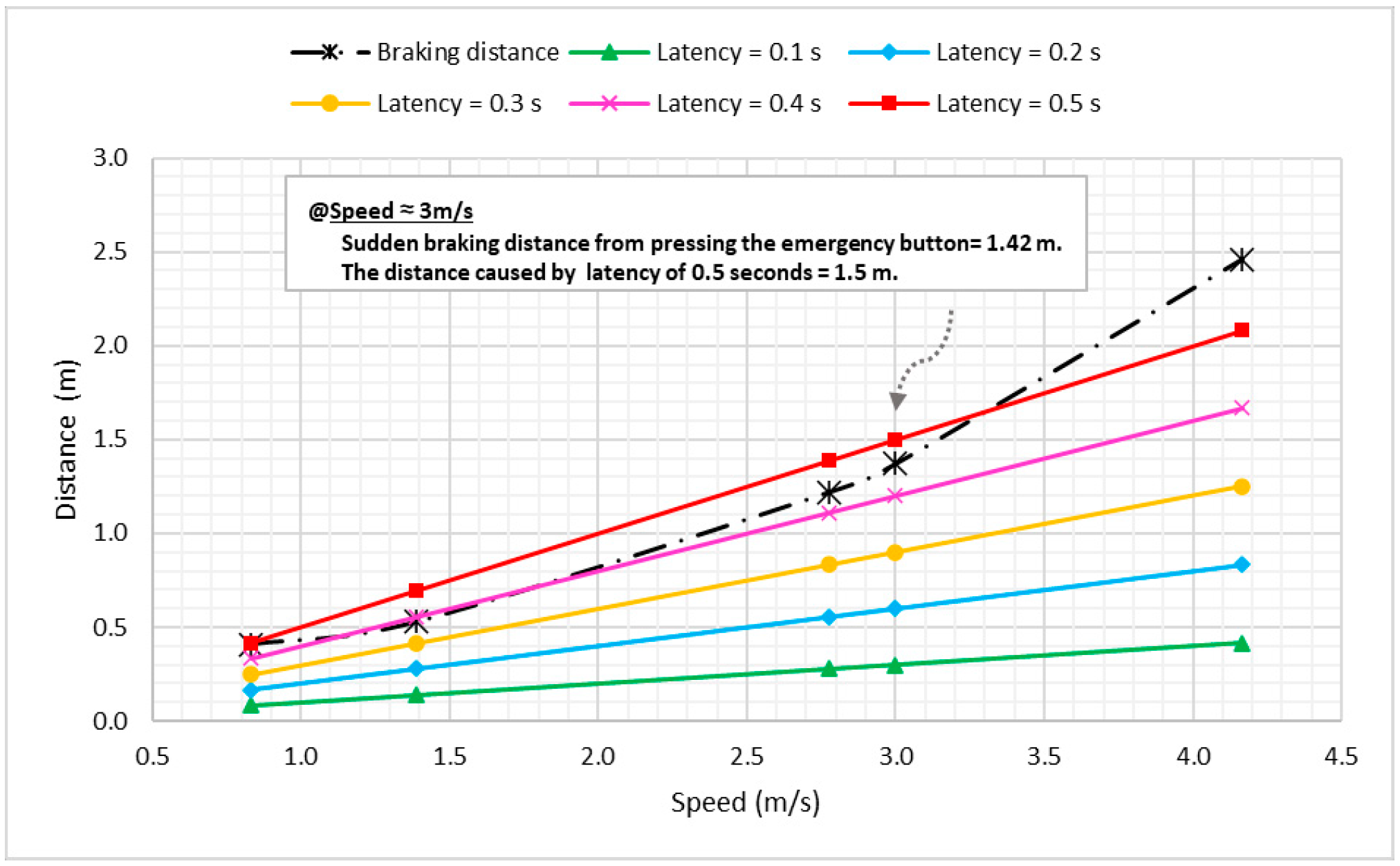
Emergency braking tests were conducted with the vehicle traveling at approximately 0.83, 1.39, 2.78, and 4.17 m/s (approximately 3, 5, 10, and 15 km/h, respectively; e.g., 10.8 km/h ≈ 3 m/s), activated via the emergency button. When the controller remotely issued brake commands, the delay resulted in increased stopping distance, as the vehicle continued to travel at its last speed before responding to the command.
Figure 12 demonstrates how braking distance under delay conditions correlates with speed and latency (400–500 ms), especially in the 0–3 m/s range. At this latency, the braking distance is nearly equal to the total distance required to stop, meaning sudden obstacles within that range could result in collisions before the operator visually registers the hazard. For latencies below 400 ms, operators may perceive obstacles in time but may still struggle to brake within the short available distance, requiring evasive steering. In some cases, the controller may be switched temporarily to autonomous mode to reduce reaction time. Based on transition tests, the highest latency recorded was 316.65 ms, and the average was 109.70 ms. With a vehicle speed of 3 m/s, braking distances at these latency values were 2.37 m and 1.75 m, respectively, as shown in
Figure 13a,b. If an obstacle appears within Zone B (before the braking distance), a collision is likely to happen unless evasive action is taken. Conversely, obstacles in Zone A (after the braking point) can be safely avoided by braking alone.
6. Comparison with Existing Systems
To contextualize the above results,
Table 1 summarizes key performance metrics of the proposed 5G teleoperation system alongside representative state-of-the-art systems from the literature. These include latency measures, path-following accuracy, braking (stopping) distances, and fallback response characteristics. All metrics are reported under experimental conditions comparable to our field trials (low to moderate speeds on closed-road circuits or testbeds).
Despite variations in experimental setup, latency performance remains comparable to recent 5G teleoperation trials. The measured average end-to-end delay (~110 ms) is well below the 170 ms threshold typically associated with minimal driving impact and is lower than the 202 ms G2G latency reported in Ref. [
24]. The worst-case delay (~317 ms) falls within the range where remote control begins to degrade, reinforcing the need for fallback mechanisms.
Lateral control accuracy (~0.2–0.3 m deviation) closely matches autonomous mode performance and aligns with sub-0.3 m benchmarks achieved using 5G mmWave and INS fusion [
36,
37]. This precision indicates that remote operation via 5G can maintain near-autonomous path-following accuracy under low-speed conditions.
Emergency braking distance increased from 1.42 m (no delay) to 2.37 m under peak latency (~316 ms), aligning with prior studies suggesting an increase of ~0.5–1 m per 200 ms delay [
24]. Automated latency-aware emergency stopping avoids added delay from human reaction time (typically 0.5–1.5 s), which remains a limitation in manual-only systems.
Compared to existing implementations, the system integrates real-time latency monitoring and autonomous braking, reducing risk without relying solely on operator intervention. Although tested at low speeds (~2.78 m/s), performance remains robust across control stability, latency management, and fallback activation.
Several limitations remain: operation under higher speeds or poor network conditions (>500 ms latency) may exceed system capabilities. Advanced predictive HMIs (e.g., GAN-based video prediction [
25], EKF-driven overlays [
26]) and curve-aware fallback maneuvers (e.g., LQR-based [
33])) represent potential areas for future enhancement. Additionally, handoff to onboard autonomy—as recommended in Level 4 guidance [
31]—could support service continuity during link loss.
In addition to latency considerations discussed above, other network impairments must also be acknowledged. Beyond latency spikes, real-world teleoperation is affected by additional network impairments such as jitter, packet loss, and bandwidth degradation. While these factors were not explicitly tested in the current study, their anticipated effects have been considered based on system architecture and the prior literature. Moderate jitter is expected to have limited impact due to buffering and frame interpolation within the video transmission pipeline. For packet loss, the control link includes a watchdog mechanism that triggers a fail-safe stop if critical commands or acknowledgments are not received within a specified timeout. This ensures that intermittent losses do not result in unsafe behavior. In cases of bandwidth degradation—such as during 5G handovers or congestion—the system adapts by reducing video resolution and frame rate to maintain responsiveness, as similarly implemented in previous 5G teleoperation prototypes [
23,
24]. If degradation persists, the fallback controller will assume command and bring the vehicle to a controlled halt. These design provisions, though not empirically validated in this study, align with best practices in resilient teleoperation and underscore the system’s ability to maintain safety even under non-ideal network conditions.
In summary, the implementation demonstrates performance and safety on par with state-of-the-art 5G teleoperation systems, particularly in moderate-speed, stable network conditions. It offers reliable control, precise trajectory tracking, and immediate fallback, with opportunities for future expansion in more demanding scenarios.
Although the current system demonstrates robust performance in small-scale field trials, its scalability to large environments (e.g., urban or highway scenarios) has not been empirically tested. Challenges such as higher speeds, longer communication distances, and multi-agent interactions remain open for future investigation. Ongoing efforts will explore these aspects in extended deployments to assess the system’s broader applicability.
7. Conclusions
This study presents the successful implementation of a real-world dual-mode driving platform that integrates low-level and high-level control systems with a 5G-based remote-control interface built on ROS and Autoware. The system allows seamless switching between autonomous and teleoperation modes, guided by real-time latency monitoring and a fallback mechanism that engages emergency braking when network conditions degrade.
The modified electric golf cart was evaluated over four structured test phases, demonstrating stable operation under various latency conditions. An abnormality detection unit actively monitored communication status and environmental input, enabling the system to transition automatically into emergency mode in response to anomalies such as latency spikes or obstacle detection. Average, minimum, and maximum latencies were 109.7 ms, 83.7 ms, and 316.6 ms, respectively, measured using ROS timestamp tools on a 5G sub-6GHz NSA network.
Trajectory tracking performance was consistent across both control modes. Remote control yielded slightly lower peak deviations, with values ranging from 0.19 to 0.25 m (average) and up to 0.41 m (maximum). Autonomous mode showed slightly higher maximum deviations, reaching 0.88 m. Emergency braking tests further revealed that latency impacts stopping distance significantly—at 3 m/s, braking distance increased from 1.42 m to 2.37 m depending on delay severity. In extreme-latency scenarios (≥500 ms), operator steering was required in addition to braking to avoid collision.
Overall, the system validates the feasibility of real-time, latency-aware dual-mode operation over public 5G networks with full hardware integration. The architecture offers a reliable and practical approach for next-generation mobility applications, with potential for future expansion into urban-scale or higher-speed environments.
Author Contributions
Conceptualization, N.N., S.C., and G.P.; data curation, K.T.; formal analysis, K.T. and S.C.; funding acquisition, N.N.; investigation, K.T. and S.C.; methodology, K.T.; project administration, N.N.; resources, N.N.; software, K.T.; supervision, N.N., S.C., and G.P.; validation, K.T. and S.C.; visualization, K.T., S.C., and G.P.; writing—original draft, N.N., S.C., and G.P.; writing—review and editing, N.N., S.C., and G.P. All authors have read and agreed to the published version of the manuscript.
Funding
This research project is supported by the Thailand Science Research and Innovation Fund Chulalongkorn University: IND_FF_68_007_2100_001.
Data Availability Statement
Any inquiry can be directly sent to the corresponding author.
Acknowledgments
This study was partially supported financially from the Special Task Force for Activating Research (STAR), Ratchadaphiseksomphot Endowment Fund, Chulalongkorn University. The tested vehicle was supported by Electric Vehicles Thailand PCL (EVT). The tested equipment and partial funding was supported by Smart Mobility Research Center, Chulalongkorn University through a research grant from Broadcasting and Telecommunications Research and Development Fund for Public Interest. Also, We would also like to thank the Immersive Technology Laboratory (IMT Lab), Faculty of Engineering, Chulalongkorn University, for their support.
Conflicts of Interest
The authors declare no conflicts of interest.
References
- Happian-Smith, J. An Introduction to Modern Vehicle Design; Butterworth-Heinemann: Oxford, UK, 2001. [Google Scholar]
- SAE Standard J3016_202104; Taxonomy and Definitions for Terms Related to Driving Automation Systems for On-Road Motor Vehicles. SAE International: Warrendale, PA, USA, 2021. Available online: https://www.sae.org/standards/content/j3016_202104/ (accessed on 15 November 2024).
- Kocsis, M.; Orban, I.; Odry, P.; Duhoky, S. A Method for Transforming Electric Vehicles to Become Autonomous Vehicles. In CONAT 2016 International Congress of Automotive and Transport Engineering; Springer International Publishing: Cham, Switzerland, 2016; pp. 752–761. [Google Scholar]
- Bertoluzzo, M.; Buja, G.; Lazzari, M. Drive-by-wire systems for ground vehicles. In Proceedings of the 2004 IEEE International Symposium on Industrial Electronics, Ajaccio, France, 4–7 May 2004; Volume 1, pp. 711–716. [Google Scholar]
- Najamuz, Z. Automotive Electronics Design Fundamentals, 1st ed.; Springer: Cham, Switzerland, 2015. [Google Scholar]
- Hafez, H.; Maged, S.A.; Abdelaziz, M. Platform Modifications Towards an Autonomous Multi-Passenger Golf Cart. In Proceedings of the 2020 2nd Novel Intelligent and Leading Emerging Sciences Conference (NILES), Cairo, Egypt, 24–26 October 2020; pp. 525–531. [Google Scholar]
- Hafez, H.; Maged, S.A.; Abdelaziz, M. Modular Design of X-by-wire Systems to Facilitate Autonomous Platform Development. In Proceedings of the 2020 8th International Conference on Control, Mechatronics and Automation (ICCMA), Moscow, Russia, 6–8 November 2020. [Google Scholar]
- Hubbard, G.A.; Youcef-Toumi, K. System level control of a hybrid-electric vehicle drivetrain. In Proceedings of the 1997 American Control Conference (Cat. No.97CH36041), Albuquerque, NM, USA, 4–6 June 1997. [Google Scholar]
- Pendleton, S.; Andersen, H.; Du, X.; Shen, X.; Meghjani, M.; Eng, Y.H.; Rus, D.; Ang, M.H. Autonomous Golf Cars for Public Trial of Mobility-on-Demand Service. IEEE Intell. Transp. Syst. Mag. 2015. [Google Scholar]
- Kanin, K.; Nuksit, N. Path following and obstacle avoidance for autonomous vehicle based on GNSS localization. In Proceedings of the 2019 International Conference on Robotics, Automation and Sciences (ICORAS), Montreal, QC, Canada, 20–24 May 2019. [Google Scholar]
- Fong, T.; Thorpe, C. Vehicle Teleoperation Interfaces. Auton. Robot. 2001, 11, 9–18. [Google Scholar] [CrossRef]
- Gnatzig, S.; Siebert, L.; Kühnlenz, K. A System Design for Teleoperated Road Vehicles. IFAC Proc. Vol. 2013, 46, 231–238. [Google Scholar]
- Lane, J.; Hamilton, B.; Thomas, J.; Vance, J.M. Effects of Time Delay on Telerobotic Control of Neutral Buoyancy Vehicles. In Proceedings of the OCEANS 2002 MTS/IEEE, Biloxi, MS, USA, 29–31 October 2002; Volume 3, pp. 2874–2879. [Google Scholar]
- Narayanan, A.; Liang, C.; Wong, L.; Xie, Y. A First Look at Commercial 5G Performance on Smartphones. In Proceedings of the 2020 Internet Measurement Conference (IMC’20), Online, 27–29 October 2020; pp. 894–905. [Google Scholar]
- Office of The National Broadcasting and Telecommunications Commission (NBTC), Thailand. 5G: คลื่นและเทคโนโลยี; Office of The National Broadcasting and Telecommunications Commission (NBTC): Bangkok, Thailand, 2018; p. 21. [Google Scholar]
- Xu, D.; Ren, J.; Xu, C.; Zhang, J.; Shen, C.; Zhang, Y. Understanding Operational 5G: A First Measurement Study on Its Coverage, Performance and Energy Consumption. In Proceedings of the 2020 IEEE INFOCOM, Online, 6–9 July 2020; pp. 479–494. [Google Scholar]
- El Rhayour, A.; Mazri, T. 5G Architecture: Deployment Scenarios and Options. In Proceedings of the 2019 International Symposium on Advanced Electrical and Communication Technologies (ISAECT), Rome, Italy, 27–29 November 2019. [Google Scholar]
- Senk, S.; Itting, S.A.; Gabriel, J.; Lehmann, C.; Hoeschele, T.; Fitzek, F.H.; Reisslein, M. 5G NSA and SA Campus Network Testbeds for Evaluating Industrial Automation. In Proceedings of the European Wireless 2021; 26th European Wireless Conference, Verona, Italy, 10–12 October 2021. [Google Scholar]
- Kato, S.; Tokunaga, S.; Maruyama, Y.; Maeda, S.; Hirabayashi, M.; Kitsukawa, Y.; Monrroy, A.; Ando, T.; Fujii, Y.; Azumi, T. Autoware on Board: Enabling Autonomous Vehicles with Embedded Systems. In Proceedings of the 2018 ACM/IEEE 9th International Conference on Cyber-Physical Systems (ICCPS), Porto, Portugal, 11–13 April 2018; pp. 287–296. [Google Scholar]
- Kato, S.; Takeuchi, E.; Ishiguro, Y.; Ninomiya, Y.; Takeda, K.; Hamada, T. An Open Approach to Autonomous Vehicles. IEEE Micro 2015, 35, 48–60. [Google Scholar] [CrossRef]
- Badue, C.; Guidolini, R.; Carneiro, R.V.; Azevedo, P.; Cardoso, V.B.; Forechi, A.; Jesus, L.; Berriel, R.; Paixao, T.M.; Mutz, F.; et al. Self-driving cars: A survey. Expert Syst. Appl. 2021, 165, 113816. [Google Scholar] [CrossRef]
- Li, S.; Zhang, Y.; Edwards, S.; Blythe, P. Quantifying the Remote Driver’s Interaction with 5G-Enabled Level 4 Automated Vehicles: A Real-World Study. Electronics 2024, 13, 4366. [Google Scholar] [CrossRef]
- 5G-Blueprint. Teleoperation in Transport and Logistics—Final Showcase Event; 5G-Blueprint Project. 2023. Available online: https://www.5gblueprint.eu/news-events/final-showcase-event (accessed on 18 June 2025).
- Testouri, M.; Elghazaly, G.; Hawlader, F.; Frank, R. 5G-Enabled Teleoperated Driving: An Experimental Evaluation. arXiv 2025, arXiv:2503.14186. [Google Scholar]
- Lee, K.W.; Ko, D.K.; Kim, Y.J.; Ryu, J.H.; Lim, S.C. Latency-free driving scene prediction for on-road teledriving with future-image-generation. IEEE Trans. Intell. Transp. Syst. 2024, 25, 16676–16686. [Google Scholar] [CrossRef]
- Sharma, G.; Rajamani, R. Teleoperation enhancement for autonomous vehicles using estimation based predictive display. IEEE Trans. Intell. Veh. 2024, 9, 4456–4469. [Google Scholar] [CrossRef]
- Kettwich, C.; Schrank, A.; Oehl, M. Teleoperation of highly automated vehicles in public transport: User-centered design of a human-machine interface for remote-operation and its expert usability evaluation. Multimodal Technol. Interact. 2021, 5, 26. [Google Scholar] [CrossRef]
- Wolf, M.M.; Taupitz, R.; Diermeyer, F. Should teleoperation be like driving in a car? Comparison of teleoperation hmis. In Proceedings of the 2024 IEEE Intelligent Vehicles Symposium (IV), Jeju Island, Republic of Korea, 2–5 June 2024; IEEE: Piscaraway, NJ, USA, 2024; pp. 3304–3311. [Google Scholar]
- Svensson, L.; Masson, L.; Mohan, N.; Ward, E.; Brenden, A.P.; Feng, L.; Törngren, M. Safe stop trajectory planning for highly automated vehicles: An optimal control problem formulation. In Proceedings of the 2018 IEEE Intelligent Vehicles Symposium (IV), Suzhou, China, 26–30 June 2018; IEEE: Piscaraway, NJ, USA, 2018; pp. 517–522. [Google Scholar]
- Kamtam, S.B.; Lu, Q.; Bouali, F.; Haas, O.C.L.; Birrell, S. Network Latency in Teleoperation of Connected and Autonomous Vehicles: A Review of Trends, Challenges, and Mitigation Strategies. Sensors 2024, 24, 3957. [Google Scholar] [CrossRef] [PubMed]
- Ding, N.; Eskandarian, A. Real-Time Teleoperation Control System For Autonomous Vehicle. IFAC-PapersOnLine 2024, 58, 168–175. [Google Scholar] [CrossRef]
- Karaböcek, İ.; Kavak, B.; Özdemir, E. Remote Control of ADAS Features: A Teleoperation Approach to Mitigate Autonomous Driving Challenges. Eng. Proc. 2024, 82, 36. [Google Scholar] [CrossRef]
- Sung, J.; Choi, S.; Huh, K. A Fallback Approach for In-Lane Stop on Curved Roads Using Differential Braking. In 16th International Symposium on Advanced Vehicle Control; Springer Nature: Cham, Switzerland, 2024; pp. 611–617. [Google Scholar]
- Lucas-Estañ, M.C.; Gozalvez, J. Sensing-based grant-free scheduling for ultra reliable low latency and deterministic beyond 5G networks. IEEE Trans. Veh. Technol. 2022, 71, 4171–4183. [Google Scholar] [CrossRef]
- Horta, J.; Siller, M.; Villarreal-Reyes, S. Cross-layer latency analysis for 5G NR in V2X communications. PLoS ONE 2025, 20, e0313772. [Google Scholar] [CrossRef] [PubMed]
- Bader, Q.; Saleh, S.; Elhabiby, M.; Noureldin, A. Enabling high-precision 5G mmWave-based positioning for autonomous vehicles in dense urban environments. arXiv 2023, arXiv:2305.02822. [Google Scholar]
- Bader, Q.; Saleh, S.; Elhabiby, M.; Noureldin, A. A step closer towards 5G mmWave-based multipath positioning in dense urban environments. arXiv 2023, arXiv:2303.01324. [Google Scholar]
- Schlenoff, C.I.; Kootbally, Z.; Rachakonda, P.K.; Lightman, S.; Vassilev, A.T.; Wollman, D.A.; Griffor, E.R. Standards and Performance Metrics for On-Road Automated Vehicles; National Institute of Standards and Technology: Gaithersburg, MD, USA, 2024. [Google Scholar]
- Escuela, G.; Stroud, N.; Takenaka, K.; Tiele, J.K.; Dannebaum, U.; Rosenbusch, J.; Törngren, M.; Niedrist, G.; Antlanger, M.; Mangold, C.; et al. Safe Automated Driving: Requirements and Architectures; The Autonomous Safety & Architecture: Vienna, Austria, 2023. [Google Scholar] [CrossRef]
| Disclaimer/Publisher’s Note: The statements, opinions and data contained in all publications are solely those of the individual author(s) and contributor(s) and not of MDPI and/or the editor(s). MDPI and/or the editor(s) disclaim responsibility for any injury to people or property resulting from any ideas, methods, instructions or products referred to in the content. |
© 2025 by the authors. Licensee MDPI, Basel, Switzerland. This article is an open access article distributed under the terms and conditions of the Creative Commons Attribution (CC BY) license (https://creativecommons.org/licenses/by/4.0/).


