Article

Design, Implementation, and Experimental Evaluation of Cross-Yagi Antennas for VHF/UHF Satellite Ground Station Applications

by
Miriam Litz Xesspe
1,
Carlos Pedrito Ccorahua
1,
Jose E. Velazco
2 and
Pablo Raul Yanyachi
1,2,*
1
Escuela Profesional de Ingeniería en Telecomunicaciones, Universidad Nacional de San Agustín de Arequipa, Arequipa 04000, Peru
2
Instituto de Investigación Astronómico y Aeroespacial Pedro Paulet, Universidad Nacional de San Agustín de Arequipa, Arequipa 04000, Peru
*
Author to whom correspondence should be addressed.
Telecom 2026, 7(3), 68; https://doi.org/10.3390/telecom7030068
Submission received: 31 December 2025 / Revised: 27 April 2026 / Accepted: 7 May 2026 / Published: 3 June 2026

Abstract

This work presents the design, simulation, fabrication, and practical evaluation of low-cost Cross-Yagi antennas for VHF/UHF satellite ground-station applications. The main contribution lies in the integrated development of a low-cost VHF/UHF antenna solution for a functional amateur satellite ground station, combining electromagnetic design, physical fabrication, and operational validation through real satellite signal reception. Two antennas operating at 145 MHz and 434 MHz were designed using Ansys HFSS, fabricated, and experimentally characterized by means of S11 and Smith chart measurements. Simulated results were used to evaluate gain, radiation characteristics, and circular-polarization behavior through axial-ratio analysis. The fabricated prototypes showed acceptable impedance performance close to the intended operating bands and a substantially lower material cost than representative commercial alternatives. Finally, the antennas were integrated into an amateur satellite ground station for real beacon reception and telemetry decoding, confirming the practical feasibility of the proposed approach for low-cost VHF/UHF satellite communication systems.

1. Introduction

Satellite communications play a fundamental role in modern telecommunication systems, particularly in emergency scenarios, remote regions, and educational or experimental environments where conventional terrestrial infrastructure may be limited [1]. In this context, satellite ground stations operating in the amateur VHF and UHF bands have attracted increasing interest because of their accessibility, operational flexibility, and relatively low implementation cost [2]. The growing use of low Earth orbit (LEO) satellites, especially CubeSats, has further increased the demand for affordable and adaptable ground station solutions [3].
Recent studies have demonstrated the feasibility of low-cost satellite ground stations based on accessible hardware and simplified architectures [4,5]. Additional efforts have explored compact telemetry reception systems in the 433 MHz band, highlighting the practical value of cost-effective solutions for small-satellite applications [6,7]. Likewise, collaborative and distributed ground station networks have shown that low-cost infrastructures can broaden satellite reception capabilities [8].
Despite these advances, most previous works have focused primarily on system-level implementations rather than on the design and experimental validation of low-cost antenna systems capable of providing both directional gain and circular polarization [9]. For satellite links, circular polarization is particularly advantageous because it mitigates polarization mismatch and improves link robustness under varying spacecraft orientation and propagation conditions [10]. In this regard, Cross-Yagi antennas represent an attractive alternative for VHF/UHF ground stations, since they combine the directional characteristics of Yagi-Uda arrays with the practical benefits of phased orthogonal arrangements for circular polarization [11].
In this context, this work presents the design, simulation, fabrication, and experimental evaluation of low-cost Cross-Yagi antennas for satellite ground station applications at 145 MHz and 434 MHz. The main contribution of this work lies in the integrated development of a low-cost Cross-Yagi antenna system for VHF/UHF satellite applications, incorporating a simplified coaxial quadrature feeding network to achieve circular polarization. In addition, the study includes the evaluation and optimization of the axial ratio in simulation, considering phase adjustments to compensate structural and coupling effects. Finally, the proposed antennas are validated at the system level through their integration into a functional amateur satellite ground station, enabling real signal reception and telemetry decoding, and demonstrating a cost-effective alternative to commercial solutions.

2. Materials and Methods

2.1. Antenna and Electromagnetic Simulation

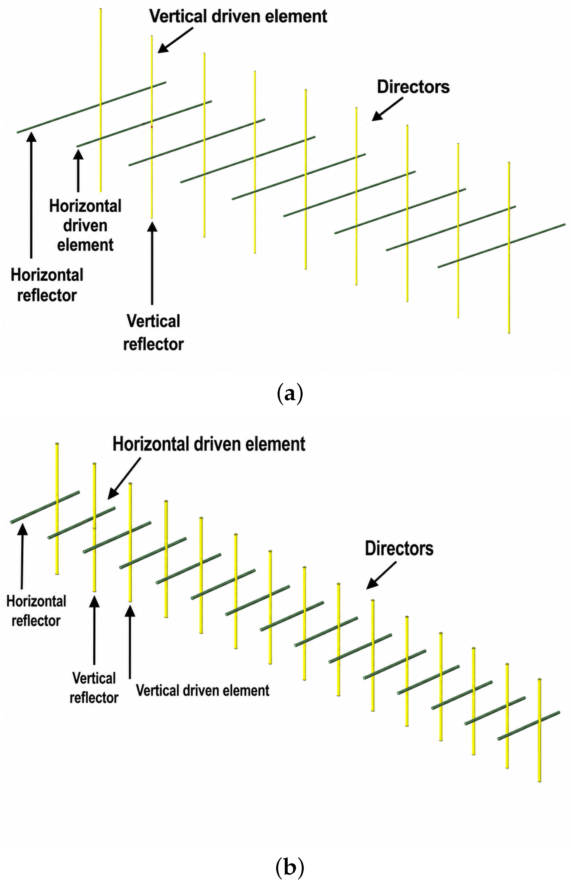
The proposed Cross-Yagi antennas for the VHF and UHF bands were modeled and optimized in Ansys HFSS 2024 R1 to evaluate their impedance matching and radiation performance. The VHF Cross-Yagi prototype consists of two orthogonal 9-element Yagi branches, each formed by one reflector, one driven element, and seven directors, resulting in 18 elements in total. Its driven element length is 92 cm (46 cm per arm if implemented as a split dipole), the maximum element length is 102 cm, and the overall boom length is approximately 2.87 m. The UHF prototype consists of two orthogonal 16-element branches, each formed by one reflector, one driven element, and fourteen directors, resulting in 32 elements in total. Its driven element length is 30 cm (15 cm per arm if implemented as a split dipole), the maximum element length is 32 cm, and the overall boom length is approximately 2.45 m. Therefore, the approximate overall antenna sizes are about 2.87 m × 1.02 m for the VHF prototype and 2.45 m × 0.32 m for the UHF prototype. Figure 1 illustrates the three-dimensional HFSS models of the proposed Cross-Yagi antennas for the VHF and UHF bands.
Antenna geometries were modeled and optimized using Ansys HFSS 2024 R1, a full-wave electromagnetic simulation software based on the finite element method widely used in RF antenna design and analysis. Each Cross-Yagi configuration consists of two orthogonally arranged Yagi–Uda antennas sharing the same boom, enabling dual linear polarization and circular polarization when an appropriate phase shift is applied, a technique commonly employed in satellite communication systems to mitigate polarization mismatch losses [10]. The design process included the definition of element lengths, inter-element spacing, boom configuration, and feed position, following established methodologies for Yagi–Uda antenna design reported in the literature [12]. Parametric sweeps were conducted to optimize impedance matching and operational bandwidth at the target frequencies. The performance of the simulated antenna was evaluated in terms of reflection coefficient ( S 11 ), voltage standing wave ratio (VSWR), input impedance, and radiation patterns, which are standard metrics for antenna characterization. Radiation boundaries were defined as open (free-space) boundaries to accurately represent operational conditions in satellite ground station environments.

2.2. Antenna Fabrication

Based on the optimized simulation results, the proposed Cross-Yagi antennas were fabricated using aluminum rods for the reflector, driven element, and directors. Printed circuit board (PCB) insulators were used to provide mechanical support and electrical isolation from the low-cost boom.
With the aim of developing an accessible solution for satellite ground stations, the prototype was constructed using low-cost, readily available materials, significantly reducing implementation costs compared to commercial antennas used in similar applications. This approach enhances system replicability in educational, experimental, and amateur radio environments.
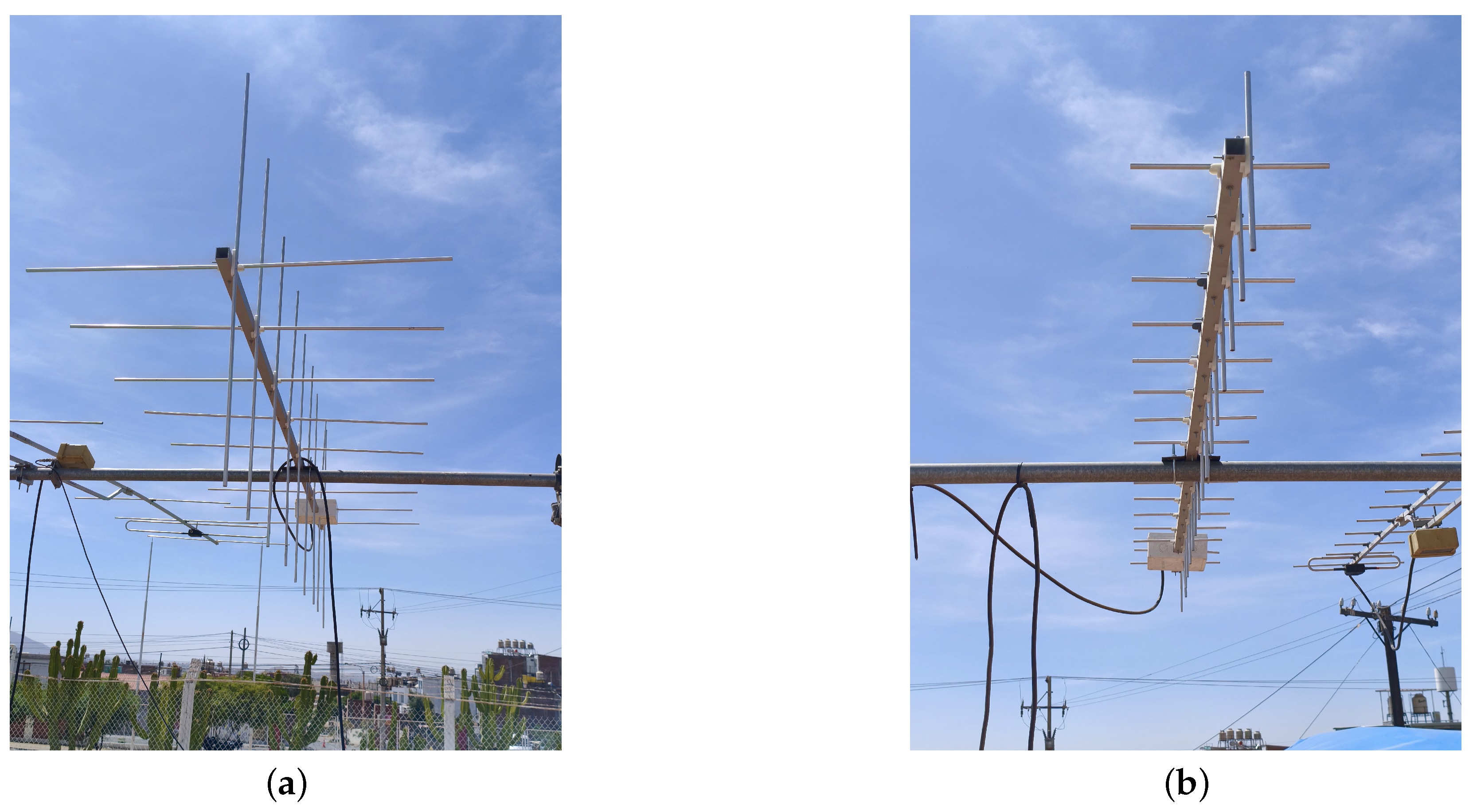
Figure 2 presents the fabricated Cross-Yagi antennas for the VHF (145 MHz) and UHF (434 MHz) bands. The orthogonal arrangement of the radiating elements along a common boom is clearly observed, a configuration that enables circular polarization when combined with an appropriate feeding network.
All element lengths and inter-element spacings were implemented according to the optimized dimensions obtained through simulation. Mechanical measurements were manually verified using precision measuring tools to minimize fabrication tolerances and deviations from the numerical model. Special care was taken to preserve the alignment and orthogonality of the crossed elements, as these factors directly affect the polarization performance of the antenna.

2.3. Feeding Network and Circular Polarization Strategy

To generate circular polarization in the proposed Cross-Yagi antenna, a coaxial feeding network was implemented to excite the two orthogonal Yagi–Uda branches with equal amplitude and a 90° phase difference. This approach is commonly used in crossed-antenna configurations for satellite applications, since it enables the generation of orthogonal electric-field components in phase quadrature, which are required to obtain circular polarization [10,13].
The feeding network was realized using a coaxial power divider that distributes the 50 Ω input signal to both antenna branches. To introduce the required phase shift, one of the branches includes a quarter-wavelength ( λ / 4 ) coaxial transmission-line section, which provides a 90° phase delay relative to the other branch. In addition, 75 Ω coaxial cable sections were used as impedance-matching elements to transform the resulting impedance of the divider to 50 Ω , thereby facilitating its connection to standard radio-frequency equipment used in satellite ground stations. This transmission-line-based matching procedure is widely employed in microwave circuits and antenna feeding structures to improve power transfer efficiency [14].
The free-space wavelength was calculated as
λ = c f ,
where c is the speed of light in free space and f is the operating frequency. The electrical length of the quarter-wavelength section is then given by
L λ / 4 = λ 4 .
Since a coaxial transmission line was used, the physical length of the phase-delay section was corrected by the velocity factor ( V F ) of the cable:
L stub = λ 4 · V F .
In this work, RG-59 coaxial cable ( 75 Ω , V F 0.66 ) was selected as a practical element of the feeding network because of its low cost, commercial availability, and adequate performance for the intended reception application. For the VHF prototype operating at 144 MHz , the free-space wavelength is
λ = 300 144 = 2.083 m ,
which yields a quarter-wavelength section of
λ 4 = 0.5208 m .
After correcting by the cable velocity factor, the physical length of the phase-delay stub becomes
L stub = 0.5208 × 0.66 = 0.3437 m 34.4 cm .
The same design procedure was applied to the UHF prototype operating at 434 MHz . In this case, the free-space wavelength is
λ = 300 434 = 0.6912 m ,
and the corresponding quarter-wavelength section is
λ 4 = 0.1728 m .
Therefore, the physical length of the phase-delay stub was calculated as
L stub = 0.1728 × 0.66 = 0.1140 m 11.4 cm .
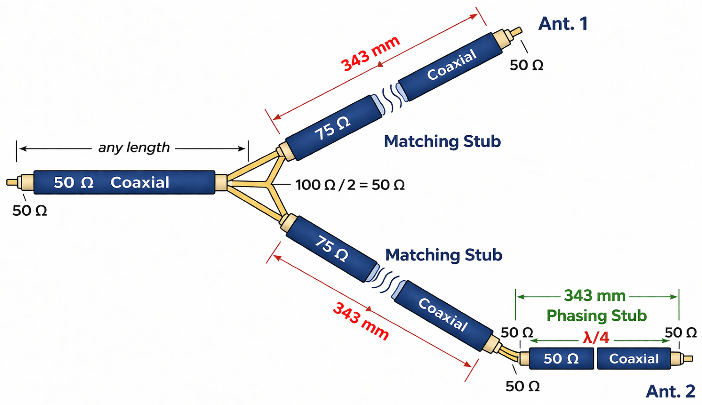
Based on this analytical procedure, quarter-wavelength coaxial sections were implemented as part of the feeding network of the proposed Cross-Yagi antennas. The circularly polarized feeding structure consisted of a quarter-wavelength phase-shift line combined with impedance-matching stubs, as illustrated in Figure 3. This configuration provides the required quadrature phase relationship between the orthogonal dipoles while preserving a simple and practical implementation [11].
No balun or dedicated common-mode choke was incorporated into the final prototype. During the experimental stage, a coaxial cable coil was tested as a rudimentary choke to mitigate possible common-mode currents and improve the impedance response. However, this element introduced a shift in the resonance frequency and altered the intended tuning; therefore, it was not included in the final implementation. Although acceptable matching performance was achieved for the intended reception application, some residual feed-line radiation or current imbalance may still remain as a limitation of the present design.

2.4. Measurement Setup

The experimental characterization of the fabricated antennas was carried out using a Rohde & Schwarz ZNB20 two-port vector network analyzer (VNA), operating from 100 kHz to 20 GHz. The main measured parameters were the reflection coefficient ( S 11 ), the voltage standing wave ratio (VSWR), and the input impedance represented through the corresponding Smith chart.
Prior to the measurements, the VNA was calibrated using a standard one-port open–short–load (OSL) procedure with a Rohde & Schwarz 3.5 mm mechanical calibration kit. During the measurement process, the coaxial cable length, connector type, SMA interconnections, instrument configuration, and test conditions were kept constant to ensure repeatability and consistency.
The same measurement protocol was applied to both the proposed Cross-Yagi antennas and the commercial Yagi antennas used for comparison. This ensured that all measurements were performed under the same electrical and experimental conditions, allowing a fair comparison between the proposed and commercial designs.

2.5. Ground Station Integration and Reception Setup

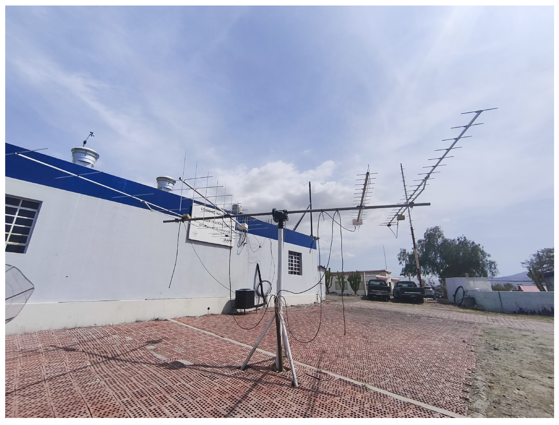
The fabricated Cross-Yagi antennas were integrated into an amateur satellite ground station composed of an azimuth–elevation rotor system, a rotor controller, a VHF/UHF transceiver, SDR-based reception tools, and satellite tracking software. Figure 4 illustrates the complete integration of the proposed antennas within the operational satellite ground station.
The azimuth–elevation rotor system enabled automatic antenna pointing based on orbital predictions, which is essential to maintain proper alignment with low Earth orbit (LEO) satellites during short visibility windows [1]. This capability is particularly important for telemetry reception, where signal levels are typically low and can vary rapidly during satellite passes.
In addition to the transceiver-based reception chain, SDR tools were used for signal monitoring and reception support during the satellite tests. In particular, SDR# was employed to visualize the received spectrum and assist in the detection and monitoring of signals in the VHF/UHF bands. This allowed the proposed antennas to be evaluated as part of a complete reception setup under realistic satellite tracking and operating conditions.

3. Results

The performance of the proposed Cross-Yagi antennas was evaluated through electromagnetic simulations and experimental measurements. The main analyzed parameters were the reflection coefficient ( S 11 ), input impedance, radiation pattern, realized gain, axial ratio, and circular polarization components (RHCP and LHCP). In addition, the practical operation of the antennas was assessed through satellite signal reception and telemetry decoding tests in the VHF/UHF bands.

3.1. Reflection Coefficient, Resonance Shift, and Input Impedance

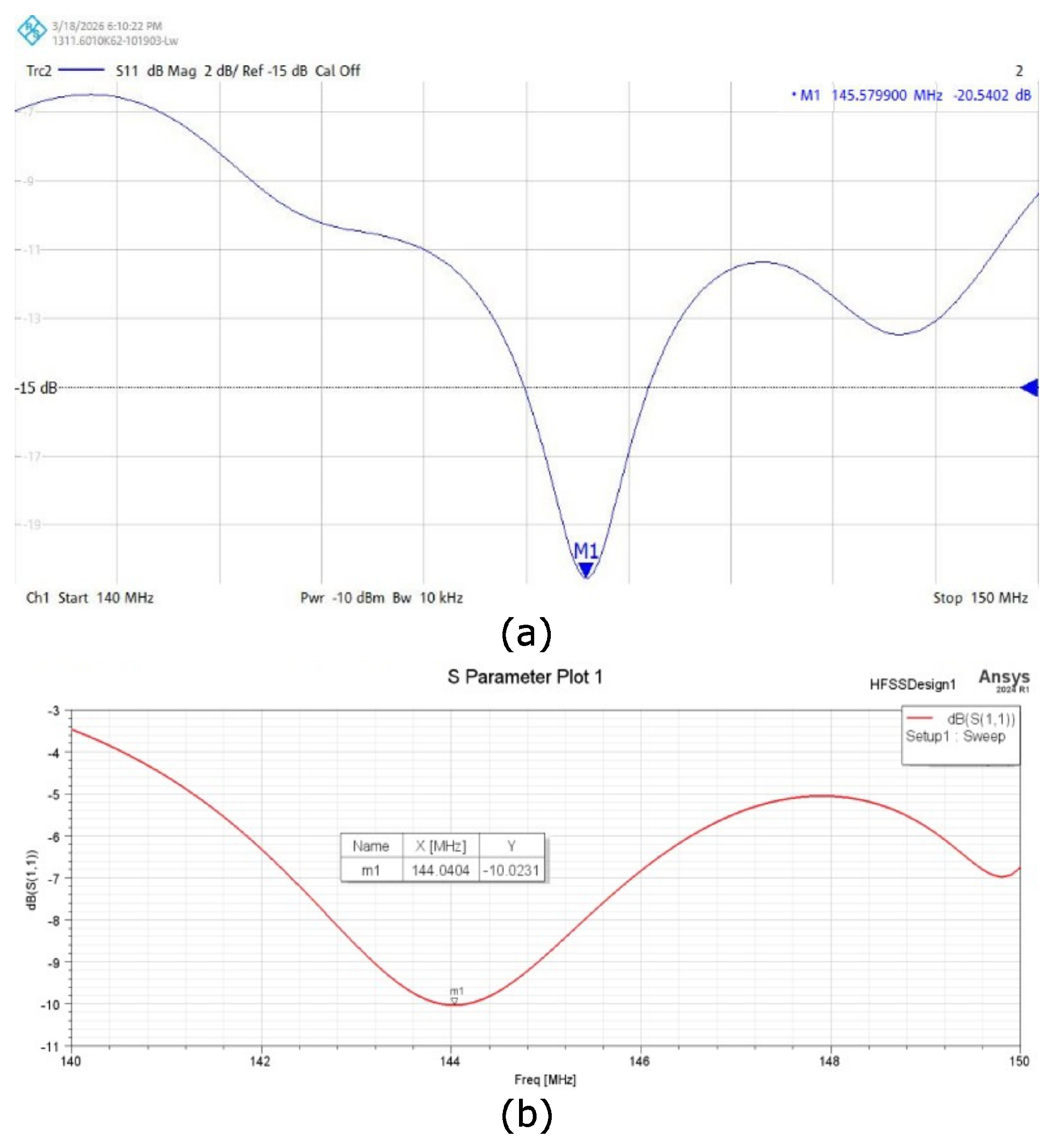
The reflection coefficient ( S 11 ) of the proposed Cross-Yagi antennas was evaluated through both HFSS simulations and VNA measurements in the VHF and UHF bands. This comparison allows the impedance-matching performance of the antennas to be assessed over the analyzed frequency range. Figure 5 presents the simulated and measured S 11 responses of the VHF prototype.
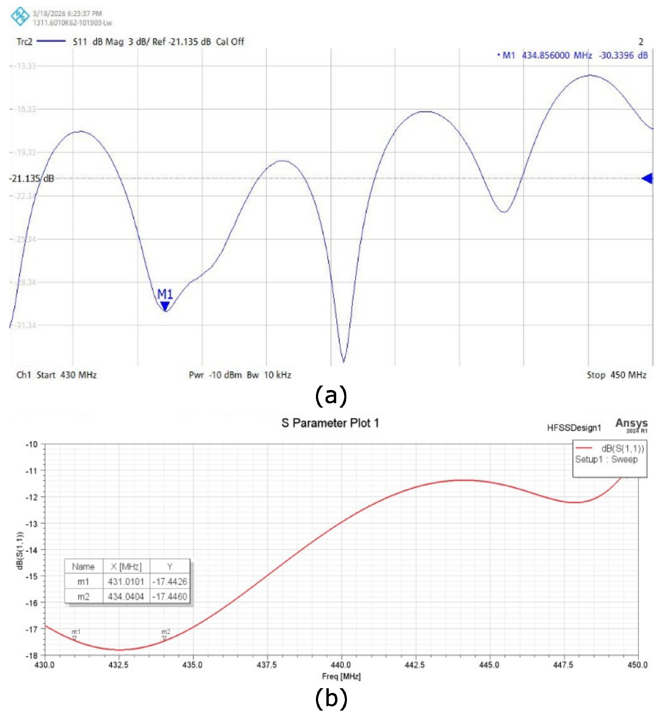
Figure 6 compares the simulated and measured S 11 responses of the UHF prototype over the analyzed frequency range.
When comparing the simulation results with the experimental measurements, a slight shift in the resonance frequency is observed. For the VHF antenna, the simulated response shows a resonance near 144 MHz, whereas the minimum measured reflection coefficient occurs around 145 MHz. Similarly, for the UHF antenna, the simulated resonance is obtained near 432 MHz, while the experimental minimum occurs around 434 MHz.
This frequency shift can be attributed to practical factors such as fabrication tolerances, small variations in the physical dimensions of the radiating elements, the influence of connectors and coaxial cables during the measurements, and simplifications introduced in the electromagnetic simulation model. Nevertheless, in both cases, the minimum measured S 11 remained close to the intended operating frequency, indicating suitable impedance matching for reception in the target bands.
The complex input impedance obtained from the VNA measurements was analyzed using the Smith chart. The antenna input impedance can be expressed as
Z = R + j X
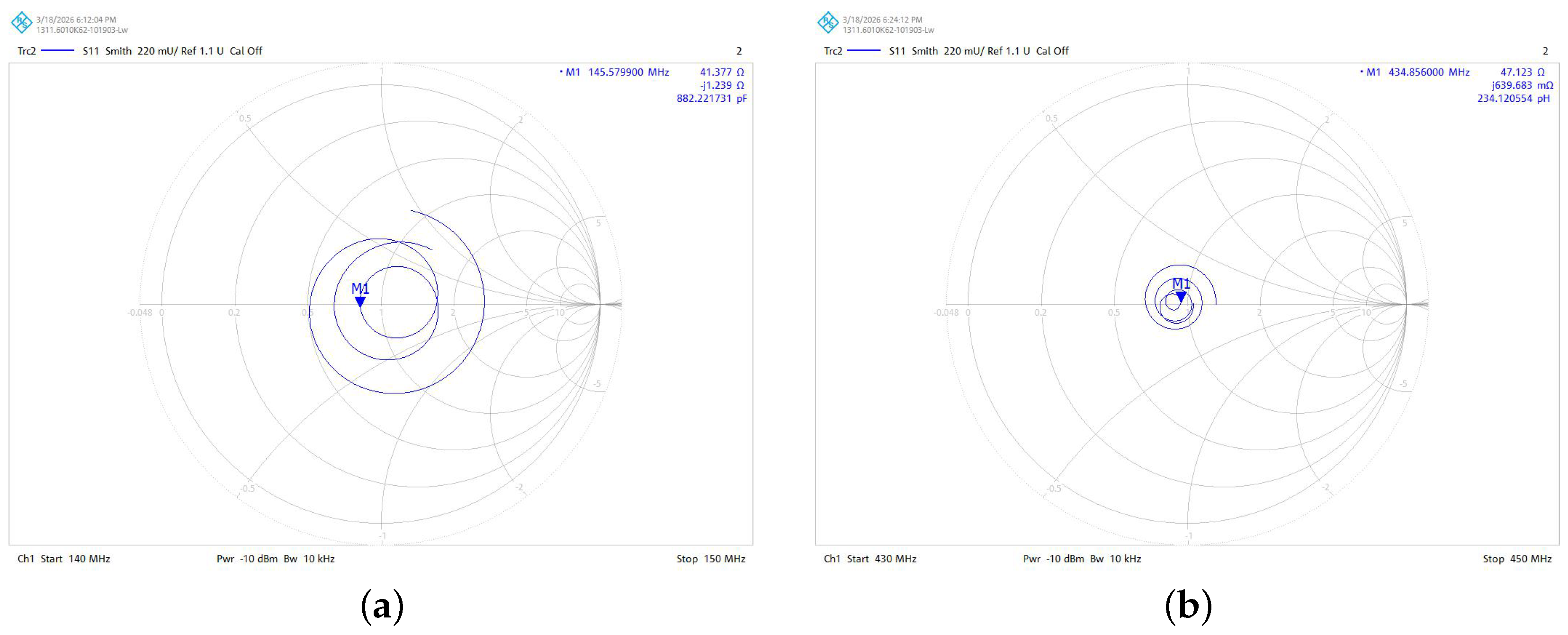
where R is the real (resistive) component and X is the imaginary (reactive) component. Around the resonance frequency, identified by the minimum of the S 11 response, the reactive component becomes smaller, indicating improved impedance matching. The corresponding measured impedance distributions for the VHF and UHF Cross-Yagi antennas are presented in Figure 7.

3.2. Bandwidth Evaluation

The antenna bandwidth was evaluated based on the reflection coefficient ( S 11 ) obtained from HFSS simulations. In antenna design, the operational bandwidth is commonly associated with the frequency range over which the antenna maintains acceptable impedance matching.
The simulation and experimental results indicate that the proposed antennas provide adequate frequency coverage around the intended operating frequencies in both the VHF and UHF bands. This behavior confirms that the proposed design achieves proper impedance matching near the central operating frequency and supports its applicability for satellite reception in the target bands.

3.3. Radiation Pattern and Gain

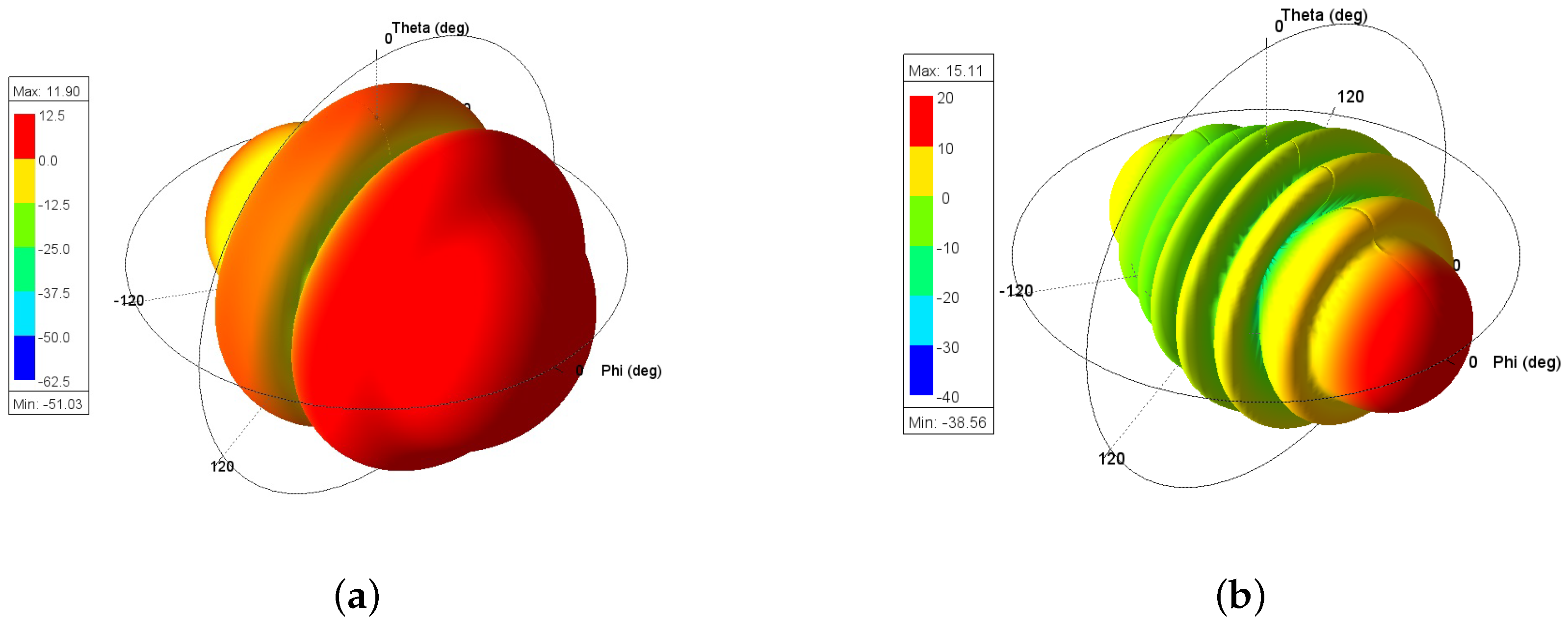
Figure 8 shows the three-dimensional gain patterns obtained from the HFSS simulations for the proposed Cross-Yagi antennas in the VHF and UHF bands. In both cases, the main lobe is oriented along the + X axis, confirming the expected directional behavior of the proposed designs.
The simulated results indicate that the proposed Cross-Yagi architecture provides suitable directional performance for satellite ground station applications in both frequency bands. For the VHF prototype, the gain pattern exhibits a well-defined main beam with a maximum gain of approximately 11.90 dB. For the UHF prototype, the antenna achieved a maximum gain of approximately 15.11 dB, indicating stronger directional performance in the UHF band.
Overall, the obtained gain patterns confirm that the proposed antennas provide the directivity required for VHF/UHF satellite reception. In particular, the higher gain achieved by the UHF design is advantageous for improving reception capability during low Earth orbit satellite passes.
It should be noted that the radiation patterns and gain values reported in this section were obtained only from HFSS simulations and were not experimentally validated through far-field antenna measurements. Therefore, these results should be interpreted as simulated performance indicators rather than as experimentally confirmed radiation characteristics.

3.4. Circular Polarization Performance (RHCP/LHCP and Axial Ratio)

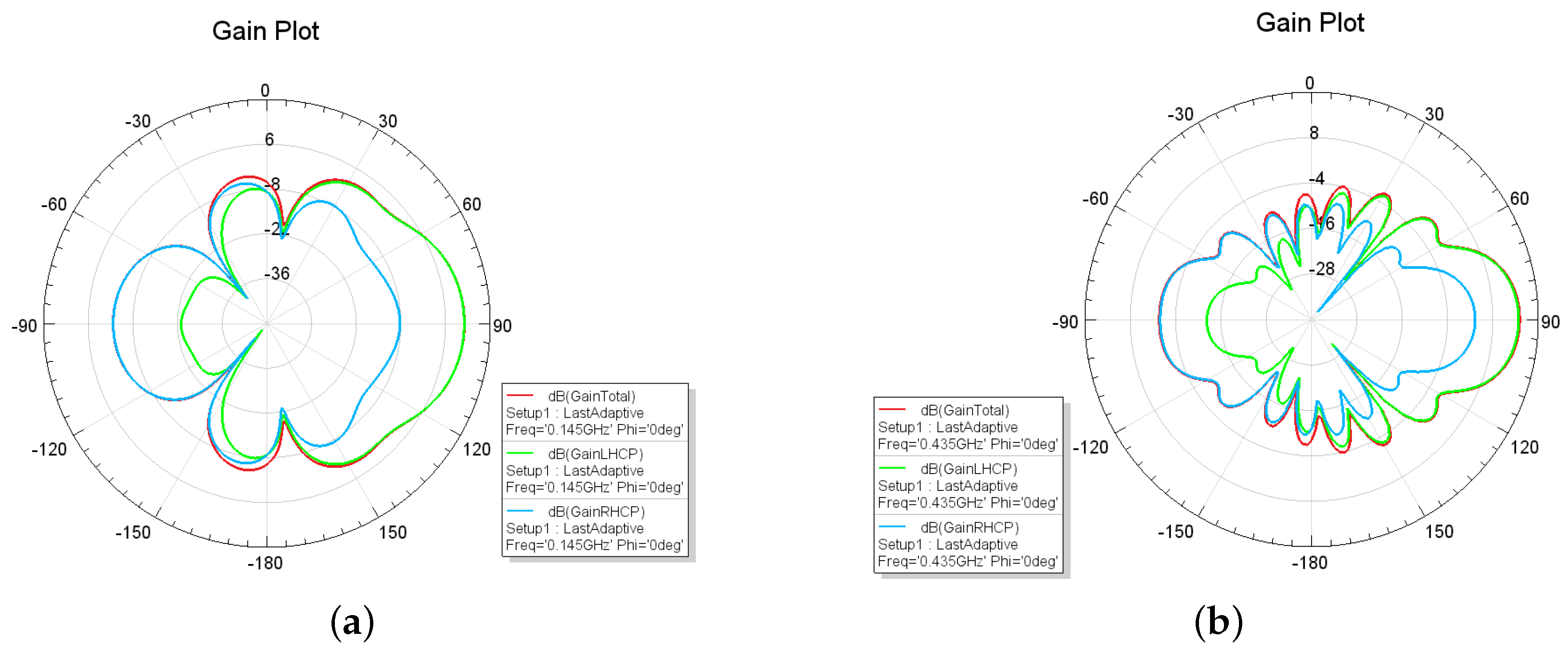
Circular polarization is a desirable feature in satellite communication systems because it helps reduce polarization mismatch losses caused by changes in satellite orientation during operation [9]. Figure 9 shows the simulated polar radiation patterns of the proposed Cross-Yagi antennas in the VHF and UHF bands, including the total gain and the right-hand circular polarization (RHCP) and left-hand circular polarization (LHCP) components.
The simulated RHCP and LHCP components confirm the polarization behavior produced by the crossed arrangement of two orthogonal Yagi arrays excited with a 90° phase difference. This configuration is intended to reduce polarization mismatch losses during satellite reception and to improve signal stability under varying satellite orientation conditions.
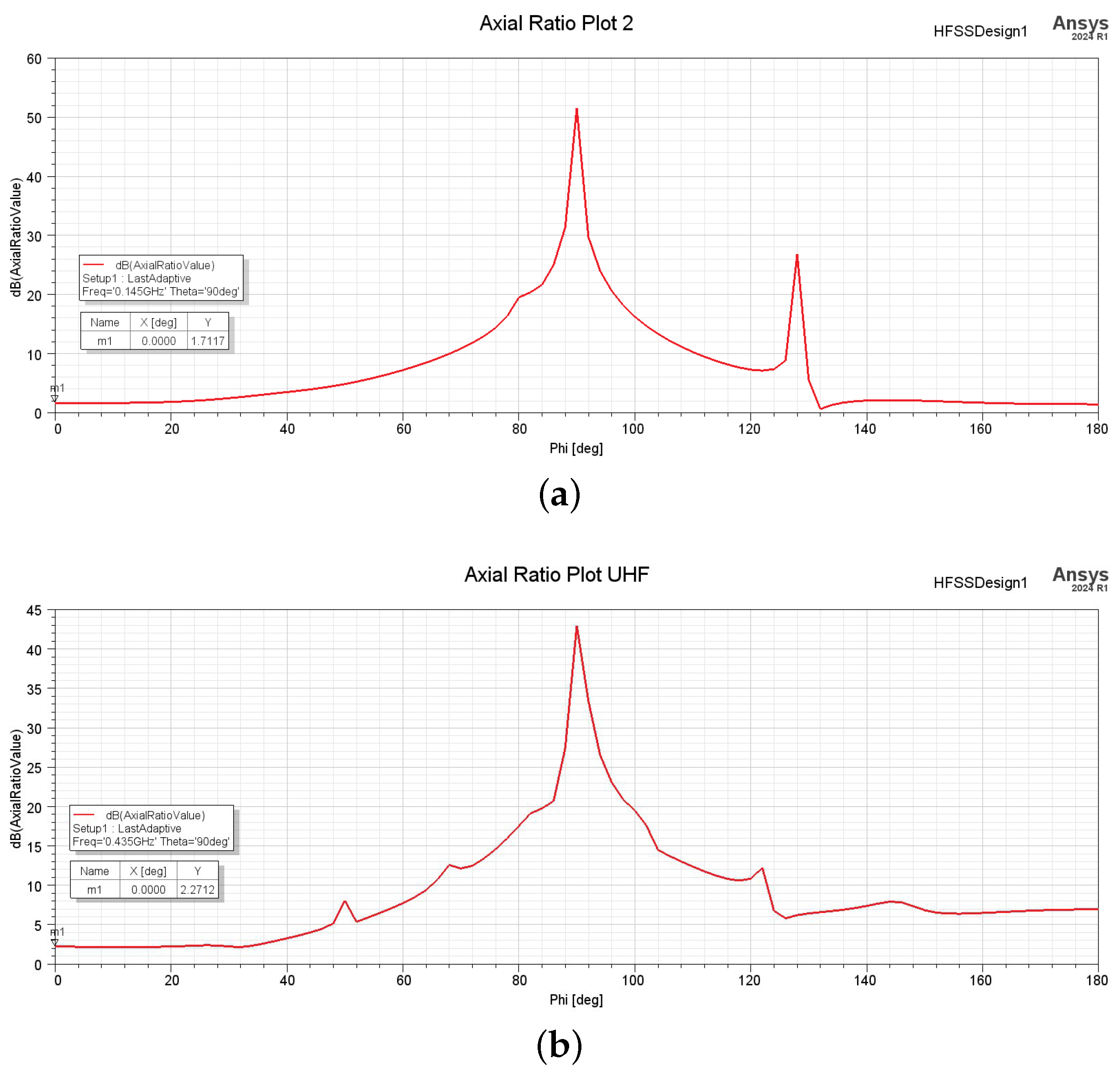
The quality of the obtained polarization was further evaluated through the axial ratio calculated in HFSS. Figure 10 presents the simulated axial ratio of the proposed antennas for the VHF and UHF prototypes.
For the VHF prototype, the simulated axial ratio reached approximately 1.72 dB at the evaluated direction, indicating good circular polarization performance. The UHF prototype, on the other hand, achieved an axial ratio of approximately 2.27 dB under the same observation conditions, the axial ratio of the UHF prototype was improved through optimization of the feeding network and antenna geometry. The updated simulation results show an axial ratio of approximately 2.27 dB in the evaluated direction, which satisfies the conventional 3 dB criterion for circular polarization. Compared to the initial design, the optimized configuration shows a noticeable reduction in axial ratio, indicating improved polarization purity in the UHF band.
This represents a significant improvement compared to the previous design iteration, where higher axial ratio values were obtained. The improvement is attributed to better phase balance and amplitude distribution between the orthogonal antenna branches.
It is important to highlight that the axial ratio and circular polarization characteristics have not been experimentally validated. The results presented are derived from electromagnetic simulations under ideal conditions. Experimental verification, including axial ratio measurements and polarization characterization, will be addressed in future work to assess the impact of fabrication tolerances and feeding network imperfections.

3.5. Comparison with Commercial Antennas

To evaluate the practical relevance of the proposed design, a comparison was carried out with representative commercial antennas commonly used in amateur satellite ground stations, based on the manufacturer specifications and listed prices reported by WiMo [15]. Table 1 summarizes the main operating characteristics of selected commercial models and the proposed Cross-Yagi antennas.
It should be noted that this comparison is intended as a practical benchmark rather than as a strict equivalence between identical antenna architectures. In particular, the commercial crossed-Yagi models employ circular polarization, whereas the conventional single-boom Yagi–Uda models are linearly polarized. Therefore, the comparison is mainly focused on frequency band, number of elements, polarization type, gain, and approximate cost.
The comparison shows that the proposed antennas operate in the same target frequency bands as the selected commercial solutions while maintaining comparable directional performance at a substantially lower prototype material cost. In particular, the proposed VHF and UHF Cross-Yagi prototypes achieved maximum simulated gains of approximately 11.90 dB and 15.11 dB, respectively, which are close to the values reported for commercial crossed-Yagi antennas intended for similar applications.
An important advantage of the proposed design is its low prototype material cost. The antennas were fabricated using accessible materials, including aluminum elements, connectors, and standard coaxial transmission lines, which significantly reduced the implementation cost. Based on the values listed in Table 1, the combined estimated material cost of both proposed antennas was approximately 75 €. However, this estimate includes only the prototype materials and excludes design, simulation, optimization, labor, assembly, and other engineering or commercial overhead costs. Therefore, the comparison with commercial antennas should be interpreted as a practical benchmark of accessibility and material cost rather than as a direct equivalence between finished commercial products and custom-built prototypes.

3.6. Experimental Satellite Reception and Telemetry Decoding

To validate the practical operation of the proposed Cross-Yagi antennas, experimental reception tests were carried out using the implemented ground station. These tests included the reception of a CW identification beacon from an amateur satellite and the decoding of telemetry signals in the VHF band using SDR-based tools and dedicated decoder software.
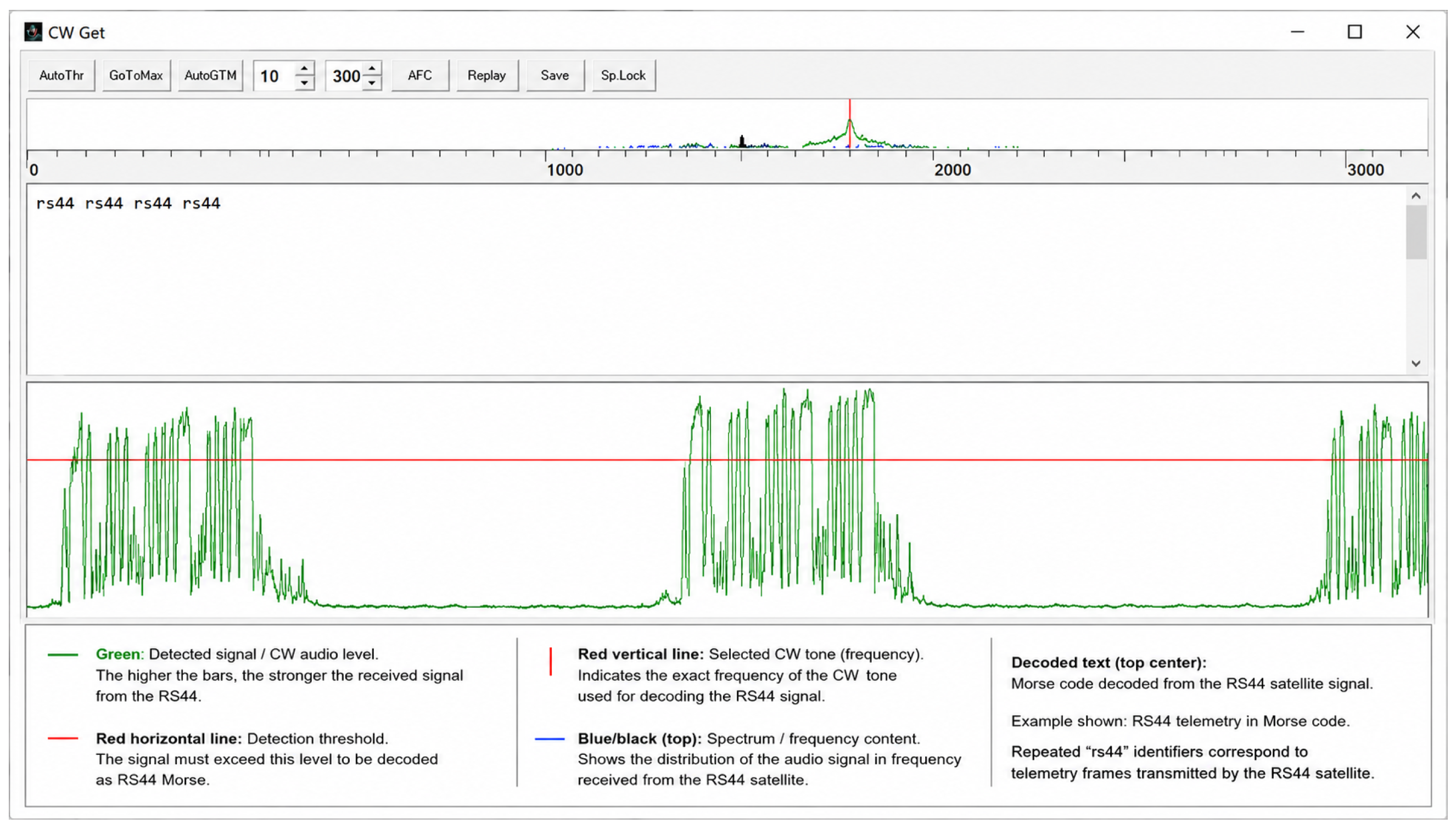
As part of the satellite reception tests, the proposed antenna system was used to receive the CW identification beacon of the RS-44 amateur satellite. According to AMSAT, the RS-44 beacon is transmitted at 435.605 MHz in CW and sends the identification “RS44” every 10 s [16]. Figure 11 shows the corresponding reception and decoding result obtained with CWget. Although simple, this result confirms the practical capability of the proposed antenna system to receive and identify real satellite signals under operating conditions.
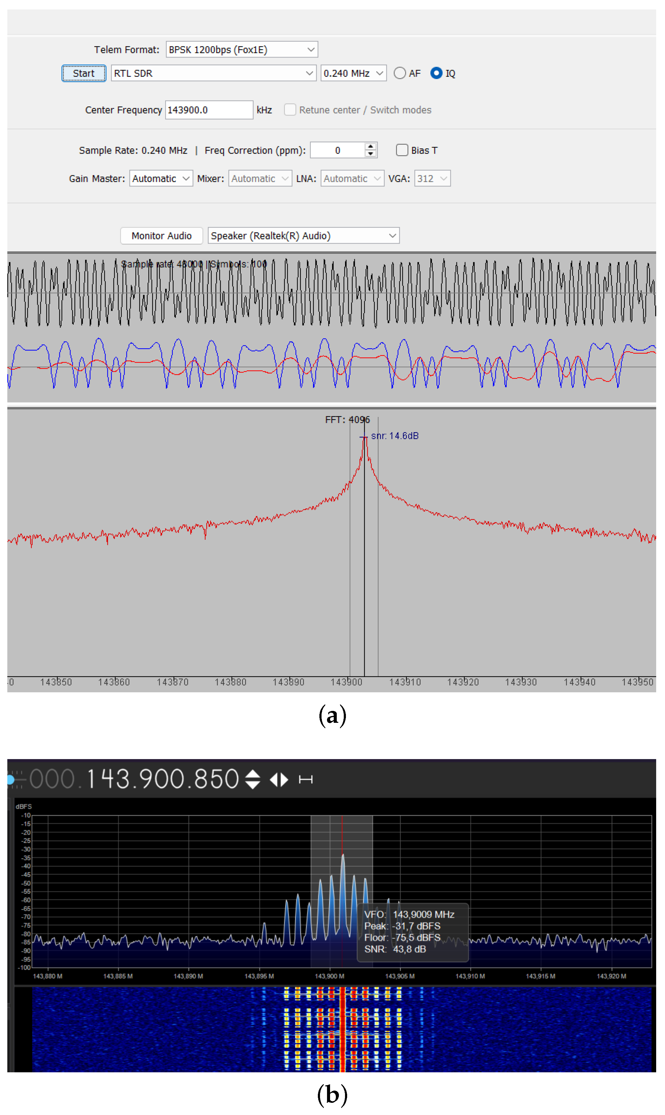
Additional reception tests were performed for telemetry monitoring in the VHF band. Figure 12 shows representative reception results obtained using FoxTelem and SDR#. In Figure 12a, the FoxTelem interface shows the reception of a BPSK telemetry signal at a bit rate of 1200 bps, with a center frequency near 143.900 MHz and a decoder-reported SNR of approximately 14.6 dB. In Figure 12b, the SDR# spectrum display shows the detected signal around 143.9009 MHz, together with software-reported indicators including a peak level of approximately 31.7 dBFS, a noise floor near 75.6 dBFS, and an on-screen SNR estimate of about 43.8 dB. These values provide quantitative visual evidence of the received signal quality during the experimental test.
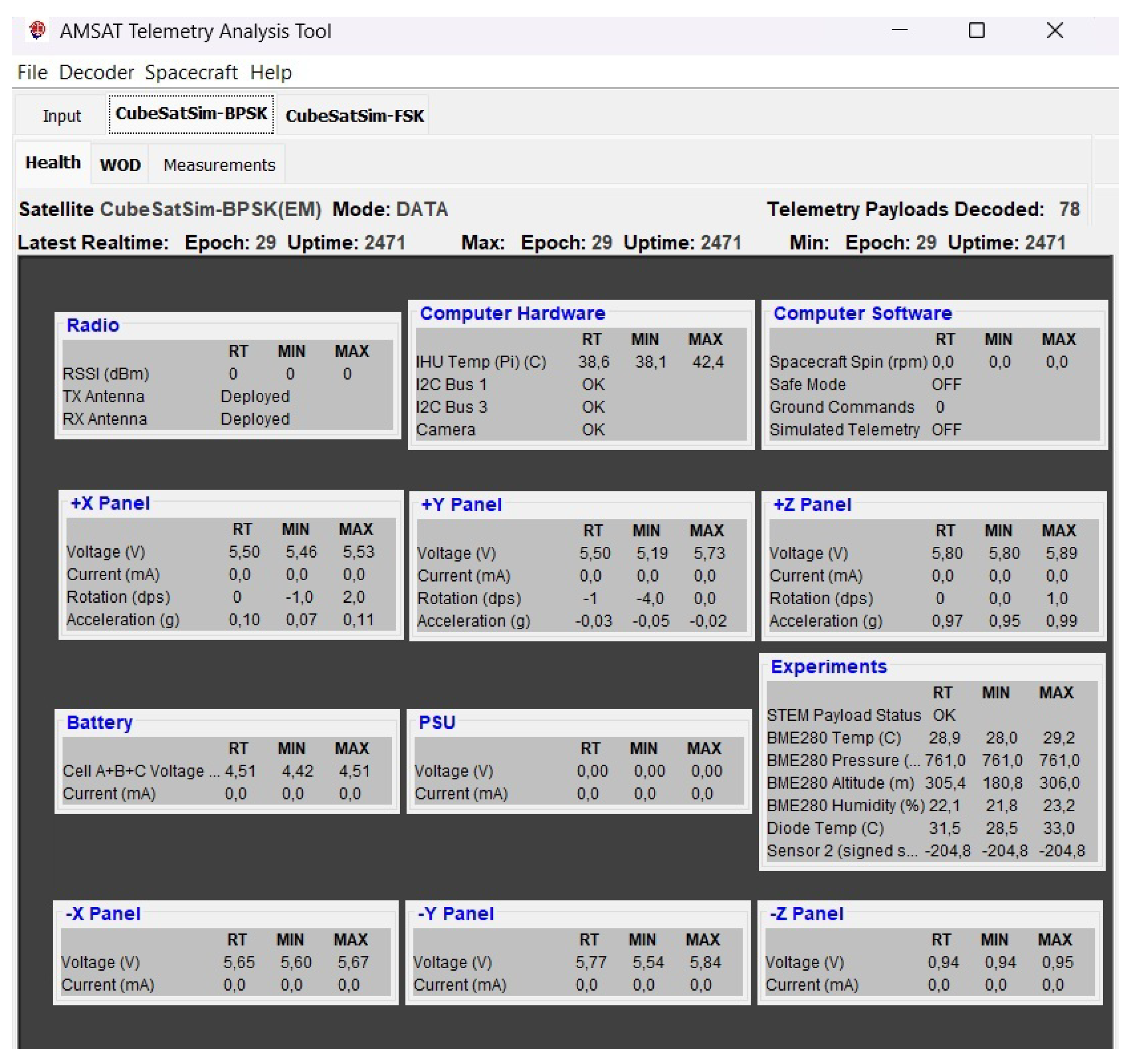
The decoded telemetry interface obtained during the reception test is shown in Figure 13. The recovered housekeeping data confirm that the received signal quality was sufficient for successful demodulation and telemetry decoding under real operating conditions. In particular, the decoding interface shows that the received transmission was properly processed by the telemetry software, providing additional evidence of the practical applicability of the proposed antenna system for experimental satellite reception.
Overall, these results confirm that the proposed Cross-Yagi antenna system provides adequate reception capability for practical satellite experiments, including real beacon reception in the UHF band and telemetry decoding in the VHF band.

4. Discussion

The obtained results indicate that the proposed Cross-Yagi antennas constitute a practical solution for satellite ground station applications in the VHF and UHF bands. The measured reflection coefficient responses showed resonance minima close to the intended design frequencies, confirming acceptable impedance matching for reception purposes.
The radiation patterns and gain values reported in this work were obtained exclusively through HFSS simulations. Therefore, these results should be interpreted as indicative of the expected antenna performance rather than as experimentally validated characteristics. Experimental far-field measurements would be required to fully confirm the radiation behavior of the proposed designs.
Circular polarization was achieved through the crossed-antenna configuration and a quadrature feeding network. Simulation results indicate that the VHF prototype achieved an axial ratio of approximately 1.72 dB, while the UHF prototype reached approximately 2.27 dB in the evaluated direction. These values satisfy the conventional 3 dB criterion for circular polarization under simulated conditions.
However, it is important to emphasize that the axial ratio and polarization characteristics were not experimentally validated. The reported results are based solely on numerical simulations and may be affected in practice by fabrication tolerances, feeding network imbalances, and measurement limitations. This represents a relevant limitation of the present work.
Compared with other antenna configurations commonly considered for satellite ground stations, such as helical, quadrifilar helix, or phased-array systems, the proposed Cross-Yagi design offers a favorable balance between material cost, mechanical simplicity, and directional performance. While more advanced solutions may provide improved polarization control or beam-steering capabilities, they generally involve significantly higher complexity and cost.
A practical comparison was established with representative commercial antennas reported by WiMo [15]. The proposed prototypes operate in the same target frequency bands and achieved gain values close to those reported for commercial crossed-Yagi antennas. However, this comparison should be interpreted as a benchmark rather than as a direct equivalence, since commercial products include manufacturing and assembly costs not considered in the prototype material estimation.
The experimental reception tests support the practical applicability of the proposed system. The successful reception of the RS-44 CW beacon in the UHF band, together with telemetry reception and decoding in the VHF band using FoxTelem and SDR#, confirms that the antennas can be effectively integrated into a functional satellite ground station.
Although signal-to-noise ratio (SNR) values were reported, a direct experimental comparison with commercial antennas under identical operating conditions was not performed. Such a comparison would provide a more rigorous evaluation of the relative performance of the proposed design.
Overall, the proposed Cross-Yagi antennas provide a useful compromise between cost, simplicity, and performance. Nevertheless, further work is required to experimentally validate radiation and polarization characteristics and to refine the antenna design for improved performance.

5. Conclusions

This work presented the design, simulation, fabrication, and experimental evaluation of low-cost Cross-Yagi antennas for amateur satellite ground station applications in the VHF and UHF bands. The proposed antennas demonstrated suitable impedance matching and operational performance for signal reception at 145 MHz and 434 MHz.
Simulation results indicate that the antennas provide directional radiation characteristics and axial ratio values consistent with circular polarization, with approximately 1.72 dB in VHF and 2.27 dB in UHF. However, these results were obtained exclusively through electromagnetic simulations and were not experimentally validated. Therefore, they should be considered as indicative of the expected performance under ideal conditions.
The experimental validation focused on practical satellite reception, where the proposed antennas successfully enabled beacon detection and telemetry decoding. These results confirm the applicability of the system in real operating conditions for amateur and educational purposes.
Although signal-to-noise ratio (SNR) values were reported, a direct experimental comparison with commercial antennas under identical conditions was not carried out. Consequently, the results should be interpreted as evidence of practical functionality rather than as a controlled comparative performance assessment.
The comparison with representative commercial antennas suggests that the proposed design offers a favorable balance between directional performance and material cost. However, this comparison is limited to indicative metrics and does not represent a direct equivalence with commercial products.
Future work will focus on the experimental validation of radiation patterns and polarization characteristics, including axial ratio measurements. Additional efforts will address improvements in the feeding network to enhance polarization purity, optimization of the antenna geometry for higher gain, and long-term outdoor evaluation. Furthermore, controlled comparative measurements with commercial antennas and detailed link-budget analysis will be conducted to provide a more comprehensive system-level assessment.

Author Contributions

Conceptualization, J.E.V. and P.R.Y.; methodology, M.L.X., C.P.C., J.E.V. and P.R.Y.; software, M.L.X. and C.P.C.; validation, P.R.Y.; formal analysis, M.L.X., C.P.C., J.E.V. and P.R.Y.; investigation, M.L.X. and C.P.C.; resources, P.R.Y.; data curation, P.R.Y.; writing—original draft preparation, M.L.X. and C.P.C.; writing—review and editing, M.L.X., C.P.C., J.E.V. and P.R.Y.; visualization, M.L.X. and C.P.C.; supervision, J.E.V. and P.R.Y.; project administration, P.R.Y.; funding acquisition, P.R.Y. All authors have read and agreed to the published version of the manuscript.

Funding

This work was supported by Universidad Nacional de San Agustín de Arequipa with contract number N°PI-16-2024-UNSA, competition “Desarrollo de un Sistema de Comunicación: Cubesat - Estación Terrena”.

Data Availability Statement

The data supporting the findings of this study, including simulation models, antenna design parameters, and experimental measurement data, are available from the corresponding author upon reasonable request.

Acknowledgments

The authors gratefully acknowledge the financial assistance provided by the Universidad Nacional de San Agustín de Arequipa—Perú to carry out this research [contract numbers: PI-16-2024-UNSA]. The authors also express their sincere gratitude to the Instituto de Investigación Astronómico y Aeroespacial Pedro Paulet (IAAPP-UNSA) for providing access to the facilities, equipment, and technical support necessary to conduct the experimental tests and measurements carried out during this research.

Conflicts of Interest

The remaining authors declare that the research was conducted in the absence of any commercial or financial relationships that could be construed as a potential conflict of interest.

Abbreviations

The following abbreviations are used in this manuscript:
VHFVery High Frequency
UHFUltra High Frequency
LEOLow Earth Orbit
HFSSHigh Frequency Structure Simulator
S11Reflection Coefficient
VNAVector Network Analyzer
VSWRVoltage Standing Wave Ratio
OSLOpen–Short–Load
SDRSoftware-Defined Radio
BPSKBinary Phase Shift Keying
CWContinuous Wave
CPCircular Polarization
LPLinear Polarization
RHCPRight-Hand Circular Polarization
LHCPLeft-Hand Circular Polarization
ARAxial Ratio
RPRadiation Pattern
SNRSignal-to-Noise Ratio
VFVelocity Factor

Appendix A. VHF Antenna Dimensions

Table A1. Geometrical dimensions of the proposed VHF Cross-Yagi antenna.
ElementLength (cm)Position (cm)
Reflector H102.000.00
Reflector V102.006.00
Dipole H92.0035.00
Dipole V92.0041.00
Director 1 H93.0072.00
Director 1 V93.0077.00
Director 2 H92.00107.00
Director 2 V92.00112.00
Director 3 H91.00142.00
Director 3 V91.00147.00
Director 4 H90.00177.00
Director 4 V90.00182.00
Director 5 H89.00212.00
Director 5 V89.00217.00
Director 6 H88.00247.00
Director 6 V88.00252.00
Director 7 H87.00282.00
Director 7 V87.00287.00

Appendix B. UHF Antenna Dimensions

Table A2. Geometrical dimensions of the proposed UHF Cross-Yagi antenna.
ElementLength (cm)Position (cm)
Reflector H32.000.00
Reflector V32.006.00
Dipole H30.0018.00
Dipole V30.0024.00
Director 1 H28.9833.00
Director 1 V28.9839.00
Director 2 H28.7049.00
Director 2 V28.7055.00
Director 3 H28.4465.00
Director 3 V28.4471.00
Director 4 H28.1681.00
Director 4 V28.1687.00
Director 5 H27.8997.00
Director 5 V27.89103.00
Director 6 H27.61113.00
Director 6 V27.61119.00
Director 7 H27.34129.00
Director 7 V27.34135.00
Director 8 H27.17145.00
Director 8 V27.17151.00
Director 9 H26.89161.00
Director 9 V26.89167.00
Director 10 H26.62177.00
Director 10 V26.62183.00
Director 11 H26.51193.00
Director 11 V26.51199.00
Director 12 H26.27209.00
Director 12 V26.27215.00
Director 13 H26.16225.00
Director 13 V26.16231.00
Director 14 H26.06240.00
Director 14 V26.06245.00

References

  1. Sharma, S.K.; Wang, X. Satellite Communication Systems for Small Satellites. IEEE Aerosp. Electron. Syst. Mag. 2017, 32, 4–17. [Google Scholar]
  2. Quiroz Olivares, A.E.; Vargas Cuentas, N.I. Low-Cost and Portable Ground Station for the Reception of NOAA Satellite Images. J. Aerosp. Technol. Manag. 2019, 11, e4519. [Google Scholar] [CrossRef]
  3. Llanga-Vargas, A.; Cabedo-Fabres, M. Design of VHF/UHF Antennas for CubeSat Using Characteristic Modes. IEEE Access 2022, 10, 78945–78956. [Google Scholar]
  4. Flores Cadena, G.F.; Lupera Morillo, P.A. Design, Construction and Testing of a Low-Cost Ground Station for CubeSat with IoT-LoRa Technology. Innov. Softw. 2024, 5, 6–19. [Google Scholar] [CrossRef]
  5. Villanueva-Maldonado, J.; Alvarez-Flores, J.L. An IoT Ground Station: Mechanics, Control, Antenna, and Reception from a LoRa Satellite Network. IEEE Lat. Am. Trans. 2023, 21, 1337–1347. [Google Scholar] [CrossRef]
  6. Simon, J.; Cardenas-Juarez, M. A Miniature IoT-Based Ground Station at 433 MHz for Reception of Telemetry Packets from LoRa Satellites. 2023. Available online: http://difu100cia.uaz.edu.mx/index.php/difuciencia/article/view/360 (accessed on 6 March 2026).
  7. Orduy Rodríguez, J.E.; Rodríguez Barón, I.F. Design of an SDR Ground Station for Low-Orbit Satellites. IEEE Aerosp. Electron. Syst. Mag. 2020, 35, 18–27. [Google Scholar]
  8. Sá Gomes, J.; Ferreira da Silva, A. TinyGS vs. SatNOGS: A Comparative Analysis of Open-Source Satellite Ground Station Networks. Telecom 2024, 5, 228–254. [Google Scholar] [CrossRef]
  9. Chen, C. Dual-Band Circularly Polarized Shared-Aperture Antenna for 1U CubeSat Applications. IEEE Trans. Antennas Propag. 2022, 70, 3818–3823. [Google Scholar] [CrossRef]
  10. Balanis, C.A. Antenna Theory: Analysis and Design, 4th ed.; Wiley: Hoboken, NJ, USA, 2016. [Google Scholar]
  11. SV1BSX. Cross-Yagi Antenna Phasing and Matching Network. Technical Diagram and Design Notes. 2020. Available online: https://www.qsl.net/sv1bsx/antenna-pol/polarization.html (accessed on 30 December 2025).
  12. Cheng, Y.; Guo, Y.J.; Wang, Y. A Novel Printed Yagi–Uda Antenna with Improved Performance for Wireless Applications. IEEE Trans. Antennas Propag. 2011, 59, 137–143. [Google Scholar]
  13. Jahanbakhshi, M.; Vertat, I. Design Investigation of Dual-Band Dual-Circularly Polarized Antenna Array. Int. J. Electron. Commun. 2022, 157, 154437. [Google Scholar]
  14. Pozar, D.M. Microwave Engineering, 4th ed.; Wiley: Hoboken, NJ, USA, 2012. [Google Scholar]
  15. WiMo Antennen und Elektronik. WiMo Online Catalog: Yagi and Cross-Yagi Antennas for VHF/UHF Bands. Available online: https://www.wimo.com/en/antennas/vhf-uhf-shf-antennas/stationary-directional-antennas-yagi-x-quad/wimo-yagi (accessed on 6 March 2026).
  16. AMSAT. RS-44. Available online: https://www.amsat.org/two-way-satellites/rs-44/ (accessed on 6 March 2026).
Figure 1. Three-dimensional HFSS models of the proposed Cross-Yagi antennas: (a) VHF configuration at 144 MHz and (b) UHF configuration at 432 MHz (dimensions are provided in the Appendix A and Appendix B).
Telecom 07 00068 g001
Figure 2. Fabricated Cross-Yagi antennas: (a) VHF antenna at 145 MHz and (b) UHF antenna at 434 MHz.
Telecom 07 00068 g002
Figure 3. Quarter-wavelength coaxial feeding network used in the proposed Cross-Yagi antenna, including impedance-matching stubs and a phase-shift stub to achieve circular polarization at 144 MHz.
Telecom 07 00068 g003
Figure 4. Integrated amateur satellite ground station employing the proposed Cross-Yagi antennas for VHF and UHF bands, mounted on an azimuth–elevation rotor system for automatic satellite tracking and telemetry reception.
Telecom 07 00068 g004
Figure 5. S 11 of the proposed VHF Cross-Yagi antenna. (a) Measured result obtained using the VNA, showing a resonance near 145.57 MHz. (b) Simulated result obtained in HFSS, showing a resonance near 144.04 MHz.
Telecom 07 00068 g005
Figure 6. S 11 responses of the proposed UHF Cross-Yagi antenna. The upper plot (a) shows the VNA measurement, with a resonance near 434.85 MHz, while the lower plot (b) shows the HFSS simulation, with a resonance near 432.5 MHz.
Telecom 07 00068 g006
Figure 7. Smith chart representation of the experimentally obtained input impedances of the proposed Cross-Yagi antennas: (a) VHF prototype; (b) UHF prototype.
Telecom 07 00068 g007
Figure 8. Three-dimensional gain patterns of the proposed antennas: (a) VHF Cross-Yagi and (b) UHF Cross-Yagi, showing the main lobe oriented along the + X propagation axis.
Telecom 07 00068 g008
Figure 9. Simulated polar radiation patterns of the proposed Cross-Yagi antennas, showing the total gain and the circular polarization components RHCP (right-hand circular polarization) and LHCP (left-hand circular polarization): (a) VHF antenna and (b) UHF antenna.
Telecom 07 00068 g009
Figure 10. Simulated axial ratio of the proposed Cross-Yagi antennas: (a) VHF prototype and (b) UHF prototype.
Telecom 07 00068 g010
Figure 11. Reception and decoding of the CW identification beacon transmitted by the RS-44 amateur satellite using the proposed Cross-Yagi antenna system.
Telecom 07 00068 g011
Figure 12. Experimental reception results obtained with the proposed Cross-Yagi antennas: (a) telemetry reception and decoding interface in FoxTelem; (b) SDR# spectrum display of the received VHF signal.
Telecom 07 00068 g012
Figure 13. Decoded telemetry interface obtained during the reception test, showing recovered housekeeping data.
Telecom 07 00068 g013
Table 1. Characteristics and approximate listed prices of representative WiMo commercial antennas and estimated material costs of the proposed antennas.
Antenna ModelCentral
Frequency
(MHz)
Number of
Elements
PolarizationGain (dBi)Approx.
Cost (€)
WiMo Yagi VHF1447Linear12.70149.00
WiMo Yagi UHF43223Linear17.15241.90
WiMo Crossed Yagis VHF14414Circular12.00299.00
WiMo Crossed Yagis UHF43236Circular16.10368.90
Proposed Cross-Yagi VHF14518Circular11.9035.00
Proposed Cross-Yagi UHF43432Circular15.1140.00
Note: The values reported for the proposed antennas correspond only to estimated prototype material costs, including connectors and construction materials. They do not include design, simulation, optimization, labor, assembly, or other engineering and commercial overhead costs. In contrast, the WiMo values correspond to listed catalog prices of finished commercial products.
Disclaimer/Publisher’s Note: The statements, opinions and data contained in all publications are solely those of the individual author(s) and contributor(s) and not of MDPI and/or the editor(s). MDPI and/or the editor(s) disclaim responsibility for any injury to people or property resulting from any ideas, methods, instructions or products referred to in the content.