
Article

Modeling the Presence of Humanoid Robots in Indoor Propagation Channels
Department of Computer Science and Engineering, University of Quebec in Outaouais (UQO), Gatineau, QC J8X 3X7, Canada
*
Author to whom correspondence should be addressed.
Telecom 2026, 7(1), 17; https://doi.org/10.3390/telecom7010017
Submission received: 12 December 2025 / Revised: 23 January 2026 / Accepted: 27 January 2026 / Published: 2 February 2026

Abstract

The increasing deployment of humanoid robots in indoor environments such as smart factories, laboratories, offices, and hospitals poses new challenges to millimeter-wave wireless communication systems. Existing human body obstruction models, while effective at characterizing pedestrian-induced signal attenuation, are not designed to directly capture the structural geometry, material composition, and controlled mobility of humanoid robotic platforms. In this work, we first reproduce a well-established human-body-based propagation model under comparable indoor conditions and subsequently extend this hybrid framework to controlled humanoid-based scenarios by combining double knife-edge diffraction (DKED) with a modified street-canyon reflection model operating at 28 GHz. Compared to existing human-based studies, the proposed approach explicitly incorporates the material properties of the humanoid robot’s envelope through a calibrated correction factor and accounts for its controlled lateral movements. An indoor measurement campaign using three programmable humanoid robots was conducted to evaluate the model. Experimental results show that humanoid robots can reproduce attenuation trends and obstruction dynamics consistent with those reported in prior human-body blockage studies, while offering improved repeatability and greater experimental control. The proposed framework provides a practical and reproducible tool for modeling indoor millimeter-wave channels under controlled humanoid-based experimental conditions, in environments involving mobile robotic agents.

1. Introduction

The increasingly widespread implementation of the Internet of Things and smart environments, including robotic platforms such as humanoids [1], is fostering their integration into indoor spaces for navigation, interaction, and service tasks. These systems often operate near humans and share the same physical space within connected homes, offices, factories, or public infrastructure [2,3]. In such contexts, wireless communication systems enabling ubiquitous connectivity increasingly face new challenges, particularly due to the dynamic nature of obstacles whose mobility is not considered in traditional modeling frameworks [4,5]. Existing indoor propagation models primarily account for static obstacles such as office furniture, factory machinery, or conference rooms, as well as human-body blockages despite their physical complexity [6,7,8]. Human-based models have proven effective in capturing shadowing and diffraction effects caused by body movements with irregular contours and heterogeneous geometry. These characteristics make human bodies inherently more difficult to model than most robots. By contrast, humanoid robots generally exhibit rigid and regular geometries with predictable surface features, and they use materials whose reflective or absorptive properties are intentionally selected and well characterized. These structural and electromagnetic differences raise the question of whether existing human-based models remain applicable when robotic agents are present in dynamic indoor scenes.
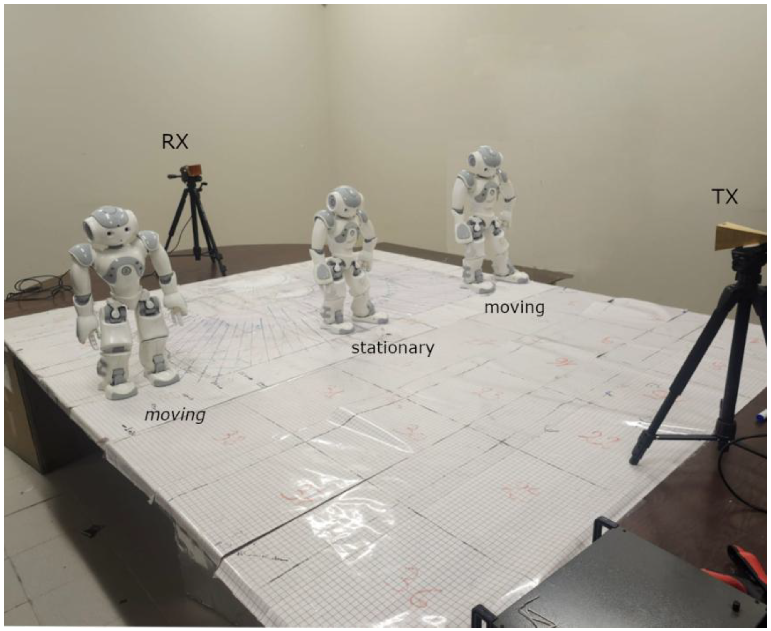
This work aims to address this gap by evaluating whether humanoid robots can serve as controlled and repeatable blockers exhibiting attenuation trends comparable to those reported for human subjects in the characterization of indoor wireless channels. A previously developed hybrid propagation model, combining DKED with a Street-Canyon approach originally designed for multiple human blockers [9,10,11], is adapted here to a 28-GHz indoor scenario involving humanoid agents. This frequency band is consistent with current millimeter-wave deployment strategies in emerging 5G and 6G systems, where accurate characterization of blockage effects is critical for link reliability [11]. To better visualize the measurement environment used in this study, Figure 1 illustrates the experimental scenario involving humanoid robots.
An important contribution of this work is to demonstrate that humanoid robots can reproduce human-like attenuation trends reported in prior human-body blockage studies under controlled conditions, while providing improved repeatability and geometric stability compared to human subjects. The methodology relies on the hybrid propagation model introduced in [11], originally designed for human-induced blockage, and extends it to scenarios involving humanoid robots as obstacles. The approach combines DKED to characterize the effect of a static central humanoid blocking the line-of-sight (LOS) and a street-canyon-inspired reflection model to capture multipath reflections generated by laterally moving humanoids. An extensive campaign of controlled measurements was conducted in an indoor environment at 28 GHz using three programmable humanoid robots positioned along the Tx–Rx link. The measured data were compared with MATLAB (R2024b, The MathWorks, Inc., Natick, MA, USA) simulations to validate the proposed model.
While the proposed approach builds upon an existing human-based hybrid propagation framework, its contribution goes beyond a simple parameter retuning for robotic platforms. This work introduces a controlled and reproducible experimental framework using programmable humanoid robots, enabling systematic isolation of geometric diffraction effects from material-dependent interactions. By explicitly incorporating the humanoid shell material properties through a calibrated correction factor and validating the model in a multi-obstacle NLoS configuration [9,10,11], the study establishes a physically grounded extension of human-body blockage models toward repeatable robotic channel characterization. The rest of this paper is organized as follows. Section 2 develops the hybrid propagation framework, combining DKED for the static central humanoid with a Street-Canyon-inspired specular component for lateral moving obstacles, and presents the unified formulation. Section 3 describes the 28-GHz indoor testbed, robot and equipment configurations, and the controlled measurement campaign. Section 4 reports the results, comparing simulated predictions to normalized measurements and analyzing discrepancies, particularly the impact of secondary reflections. Finally, Section 5 presents conclusions and outlines directions for extending the model to richer dynamics and material effects.

2. Materials and Methods

2.1. Measurement Setup

The measurements were conducted at 28 GHz, a representative millimeter-wave frequency widely used for indoor short-range communication scenarios in emerging wireless systems [7]. This choice allows direct comparison with existing human-body blockage studies reported in the literature at similar frequencies, where diffraction- and reflection-based attenuation mechanisms have been extensively investigated [10,11]. The selected measurement bandwidth provides a trade-off between frequency resolution and measurement stability, ensuring reliable received-power estimation under controlled experimental conditions. Indoor channel measurements were performed using a Keysight N9952A (Keysight Technologies, Santa Rosa, CA, USA) vector network analyzer (VNA) connected to two standard-gain horn antennas (Millitech SGH-28-SP000 (Northampton, MA, USA), 24 dBi nominal gain, ≈18° HPBW in both H and V planes). The antennas were co-polarized in TE mode, with their rectangular apertures oriented so that the electric field remained perpendicular to the plane of incidence defined by the Tx–robot–Rx geometry. The transmitting antenna continuously illuminated the receiving antenna using a CW signal at 28 GHz. Gore-type low-loss coaxial cables (W. L. Gore & Associates, Newark, DE, USA) and precision 2.92 mm connectors (Rosenberger, Fridolfing, Germany) were used to minimize attenuation between the VNA and the antennas.
The measurement environment consisted of a 2 m indoor link with antennas positioned at a height of 1.30 m. Three programmable humanoid robots (SoftBank Robotics, Paris, France) (≈56 cm height) were placed on an 80 cm table along the Tx–Rx line. The structural composition of the humanoid chassis includes an ABS–PC polymer shell and PA-66/XCF-30-reinforced internal components, according to the official construction specifications for the NAO platform [12], providing stable and repeatable EM surface interactions. This further supports their suitability as controllable electromagnetic test subjects. One humanoid acted as a stationary central blocker, while the two lateral humanoids reproduced basic human-like movements at a constant speed. A personal computer was used to program, synchronize, and control robot motion. The mobile humanoids moved laterally from 1.0 m to 0.6 m from the line-of-sight (LOS) in successive 10 cm increments, while the central robot remained fixed. At each position, the received complex field was recorded using the VNA in zero-span mode. At each humanoid position, the received complex field was recorded using the VNA in zero-span mode. The received power was then evaluated using the channel power function with temporal averaging enabled. Specifically, 15 consecutive sweeps were recorded and averaged at each lateral offset. Under these conditions, short-term fluctuations of the received power remained limited, indicating good measurement stability within the indoor environment. All measurements were normalized to the received power at the 0.6 m reference position. Figure 1 illustrates the complete experimental setup, including antenna placement, robot positioning, and measurement geometry. Similar humanoid LOS blockage configurations have been reported in previous indoor propagation studies [9], and the antenna configuration and measurement procedure are consistent with established indoor channel characterization standards such as ITU-R P.1238-13 [13]. In addition, the dielectric characteristics of the humanoid shell materials are within the permittivity ranges reported for indoor polymeric and composite structures [14].

2.2. Hybrid Propagation Model

2.2.1. Notation and Conventions

Throughout this paper, boldface symbols (e.g., E) denote vector quantities, while scalar quantities are written in italic typeface. For simplicity of presentation, vector arrows may be omitted in tables and figure captions when no ambiguity arises, while the vector nature of the electromagnetic fields is preserved in mathematical formulations. The visibility indicator is consistently denoted by V i , where V i = 1 indicates that a specular path is visible from both transmitter and receiver, and V i = 0 otherwise. This notation is used uniformly across all sections.
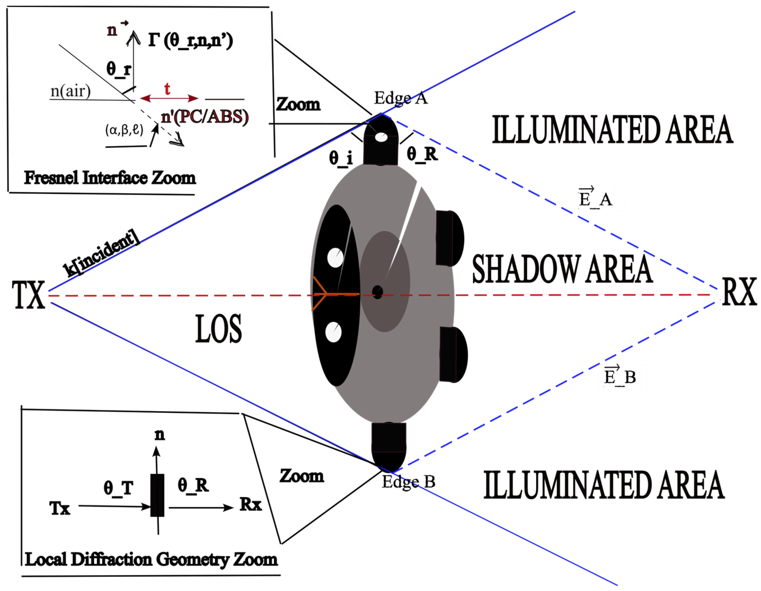
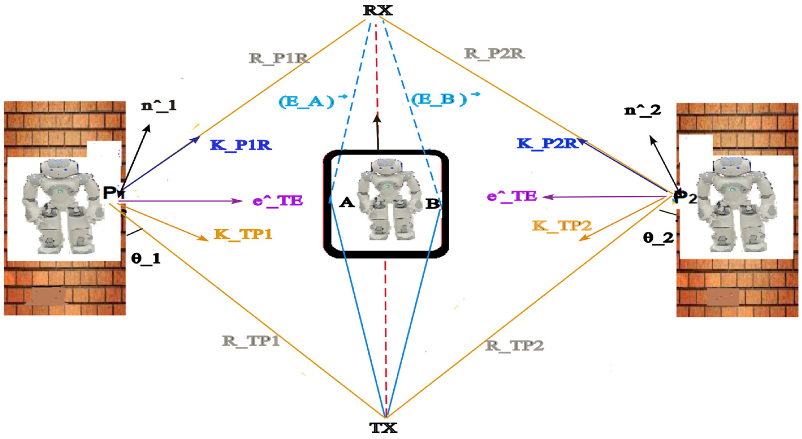
The Humanoid-Adapted Hybrid Model, developed as an extension of the Human-Based Hybrid Model proposed in [9,10,11], accounts for humanoid-induced diffraction and reflection near the line of sight, reproducing the characteristic attenuation and multipath effects observed in short-range 28 GHz indoor scenarios. Thus, we classify humanoid obstacles into two types. The central humanoid mainly introduces a double-edge diffraction effect at its two vertical edges (as detailed in Figure 2), whereas the lateral robots primarily contribute to specular and secondary reflections occurring on their side-facing shell surfaces, as illustrated by the propagation paths in Figure 3. Each category is modeled using propagation mechanisms adapted to their respective positions and electromagnetic interactions. In the following subsections, we present in detail the geometry, the theoretical basis, and resulting and referenced equations of the DKED-based and Street-Canyon-inspired models, followed by a unified formulation used in our simulations and comparisons. The formulation and calibration presented in this work are based on a standing neutral humanoid posture with fixed limb configurations and controlled lateral motion, which serves as a reference scenario for repeatable indoor measurements. For clarity, Table 1 summarizes the main parameters involved in the proposed hybrid DKED–Street-Canyon formulation, along with their physical interpretation and sensitivity to humanoid posture.

2.2.2. DKED Component for the Central Humanoid

The humanoid is considered as a vertical opaque screen with two diffracting edges as shown in Figure 2, which provides a top-view representation of the double knife-edge diffraction (DKED) geometry induced by a static humanoid blocking the line of sight. The central humanoid acts as a double knife-edge obstacle, where edges A and B generate diffracted fields that illuminate the receiver region while creating a shadow zone along the direct LOS. The illuminated and shadowed regions illustrate the dominant diffraction mechanisms captured by the DKED model. The zoomed insets highlight the local diffraction geometry at the edges and the Fresnel interface used to account for material-dependent reflection and transmission effects. DKED-based field strength is expressed as follows:
E DKED = E A + E B
where E A   and   E B represent the diffracted contributions from edges A and B. To account for the PC/ABS (Polycarbonate/Acrylonitrile Butadiene Styrene) and metallic structure of the humanoids, which differ from biological absorption characteristics [10,11,15], we apply a correction factor calibrated from measurements as in [9] (Section V, Figure 8). The geometric rationale follows the near-field obliquity framework discussed in [16] (Section 2).
E DKED corr = ( E A + E B ) F adj
Here F adj is the product of F geom and F mat that implements the geometric obliquity weighting of the diffracted fields, consistent with scalar diffraction theory (modified Huygens–Fresnel) [16,17] (Section 2; Section 3.4.3 and 3.5.2). F mat captures the material contrast between humanoids (PC/ABS plastic shell) and the human body; The humanoid parameters are calibrated from measurements, as in [9] (Section V, Figure 8). The factor F adj is applied only to the diffracted term ( E A + E B ) to correct the pre- and post-shadow discrepancies observed with DKED. Specular paths are not re-weighted, since Fresnel-based reflection is already incorporated in the specular components of the propagation model, consistent with ITU-R indoor channel recommendations [13], while the explicit reflection coefficient Γ is computed according to standard Fresnel formulations [18,19].
The dielectric properties of the humanoid shell material (PC/ABS) were not directly measured in this work. Nominal values of the relative permittivity were initially selected from representative ranges reported in the literature for common polymeric materials at millimeter-wave frequencies, such as plexiglass, polypropylene, and polystyrene, whose dielectric behavior is comparable to that of PC/ABS blends at 28 GHz [14]. These values are used as indicative ranges rather than exact material constants, motivating the introduction of the calibrated material correction factor F mat , which was calibrated using the measured received power levels in the unobstructed and blocked configurations. As a result, F mat should be interpreted as an effective correction factor that captures the combined influence of the humanoid shell material, its finite thickness, and near-field interaction effects under the specific experimental configuration considered. The calibration was performed for a fixed humanoid posture and surface condition, and the same F mat was consistently applied across all measurement positions in this study. It is worth noting that changes in humanoid pose, the addition of clothing or surface coverings, or the use of alternative shell materials would alter the effective electromagnetic interaction and would therefore require re-calibration of F mat . The present formulation is thus intended to provide a controlled and repeatable reference scenario rather than a universal material parameter, enabling fair comparison between simulations and measurements in a well-defined indoor setup. A summary of the parameters involved in F geom and F mat is provided below for clarity.
F geom = cos θ T cos θ R
F mat = exp ( α )   exp ( j β ) .
E c = E ( j   σ ω E 0 ) .
n = E c = n jk .
α = K 0 k .
β = K 0 n .
= t cos θ t .
k 0 = 2 π λ .
F adj = cos θ T cos θ R   ( exp ( α ) exp ( j β ) )
  • α attenuation coefficient in the material
  • β phase coefficient in the material
  • effective path length in the material
  • k 0 free space wavenumber
  • t material thickness (along the surface normal)
  • k wavenumber in the material
  • n real part of the refractive index
  • n complex refractive index
  • θ t transmission angle inside the material (Snell’s Law)
  • θ R RX obliquity angle used in   F geom
  • θ T TX obliquity angle used in   F geom
  • θ r reflection angle (equal to the incidence angle)
  • E absolute permittivity   ( E = E E 0 )
  • E real part of the relative permittivity
  • E c complex relative permittivity
  • ω angular frequency   ( ω = 2 π f )

2.2.3. Street-Canyon Component for Lateral Moving Humanoids

The two lateral humanoids are placed symmetrically with respect to the LOS and are modeled as specular reflectors (as shown in Figure 3). For reflector i ∈ {1, 2}, let P i be the reflection point, θ i the incidence angle at P i , and:
r i r TP i + r P i R .
The total geometric length of the specular path. The LOS Tx–Rx distance is r TR . specular component (normalized by the LOS reference). With co-polarized vertical horns, Fresnel terms are evaluated in TE polarization. The specular field from reflector i is:
E SC , i = V i α i Γ i TE θ i ; E c E LOS .
where V i ∈ {0, 1} is a visibility indicator (the term is included only if P i is visible from both Tx and Rx), and Γ i TE ( θ i ; E c ) is the TE Fresnel reflection coefficient at incidence θ i for the air humanoid–shell interface with complex relative permittivity [20].
n = E c .
following the standard formulation of the complex refractive index for lossy dielectrics in mmWave indoor propagation modelling [18,19,21].
The factor α i captures only free space spreading and the extra phase due to the longer path (no material or polarization dependence):
α i = r TR r i   exp   [ j   k 0 ( r i r TR ) ] ,
Equation (13) states that the lateral humanoid returns a scaled and phase–shifted copy of the LOS field: Γ i TE encapsulates material/polarization effects at the interface, while α i accounts for geometry only ( 1 r spreading and differential phase). Visibility V i enforces that only feasible specular paths contribute.
  • This formulation follows the classical street-canyon reflection approach used in millimeter-wave propagation studies, where lateral structures act as specular reflectors (see, e.g., Rappaport et al. [10]). While this model is traditionally applied to large-scale urban environments, we extend the same principles to the humanoid lateral reflectors, which behave as mobile specular surfaces under TE polarization, modifying Fresnel reflection conditions and visibility factors as their positions evolve relative to LOS. The final received field combines the corrected DKED contribution of the central humanoid with the dual specular street-canyon terms from the lateral humanoids.
In this framework, the street-canyon component is limited to first-order specular reflections from the dominant lateral humanoid surfaces. Higher-order reflections are not explicitly included, as their contribution rapidly decreases due to increased propagation distance, additional reflection losses, and reduced visibility conditions. Preliminary numerical evaluations indicated that the inclusion of higher reflection orders provides only marginal accuracy improvement compared to the resulting increase in model complexity. As a representative numerical example, for a lateral offset of 0.9 m, the inclusion of an additional reflection order modifies the predicted received power by less than 0.2 dB compared to the first-order street canyon formulation. This variation remains significantly smaller than the overall attenuation levels observed in the measurements, confirming that higher-order reflections provide only marginal benefit in the considered configuration. Furthermore, considering those higher-order reflections interactions would considerably increase model complexity and computational burden, without providing a commensurate improvement in accuracy for the short-range indoor configuration considered here. The resulting total field expression is presented in Section 2.2.4.

2.2.4. Unified Field Formulation

The received field is modeled as the coherent superposition of three components: the LOS contribution, the corrected DKED induced by the central humanoid, and the two lateral reflections (Section 2.2). Visibility masks are introduced so that only physically feasible propagation paths contribute to the total field. The LOS component is included only if the direct path is not blocked by the central humanoid, through the binary visibility factor V LOS { 0,1 } . Similarly, each specular Street-Canyon component is included only if its corresponding reflection point is visible from both the transmitter and the receiver, through individual binary visibility indicators V i { 0,1 } .
E total = V LOS E LOS + E DKED corr + i = 1 2 E SC , i ,
E DKED corr = ( E A + E B ) F adj
For comparison with measurements, we also use a normalized form obtained by dividing by the unobstructed LOS reference E LOS , ref (same geometry and frequency without blockers):
E total , norm E total | | E LOS , ref | | = V LOS + E A + E B | | E LOS , ref | | F adj + i = 1 2 V i α i Γ i TE θ i ; E c .
This expression separates material/polarization effects (only in Γ i TE ) from geometric/phase effects. Secondary bounces can be added on top of this baseline model.

3. Results

This section presents the normalized measurement results obtained with humanoid robots, compares them with the predictions of the hybrid propagation model, and evaluates the impact of secondary reflections and multipath components on the accuracy of the model.

3.1. Normalized Measurement Results

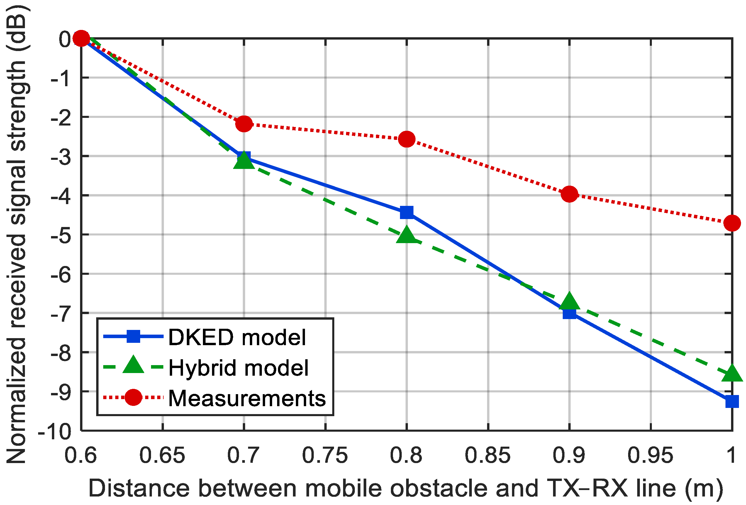
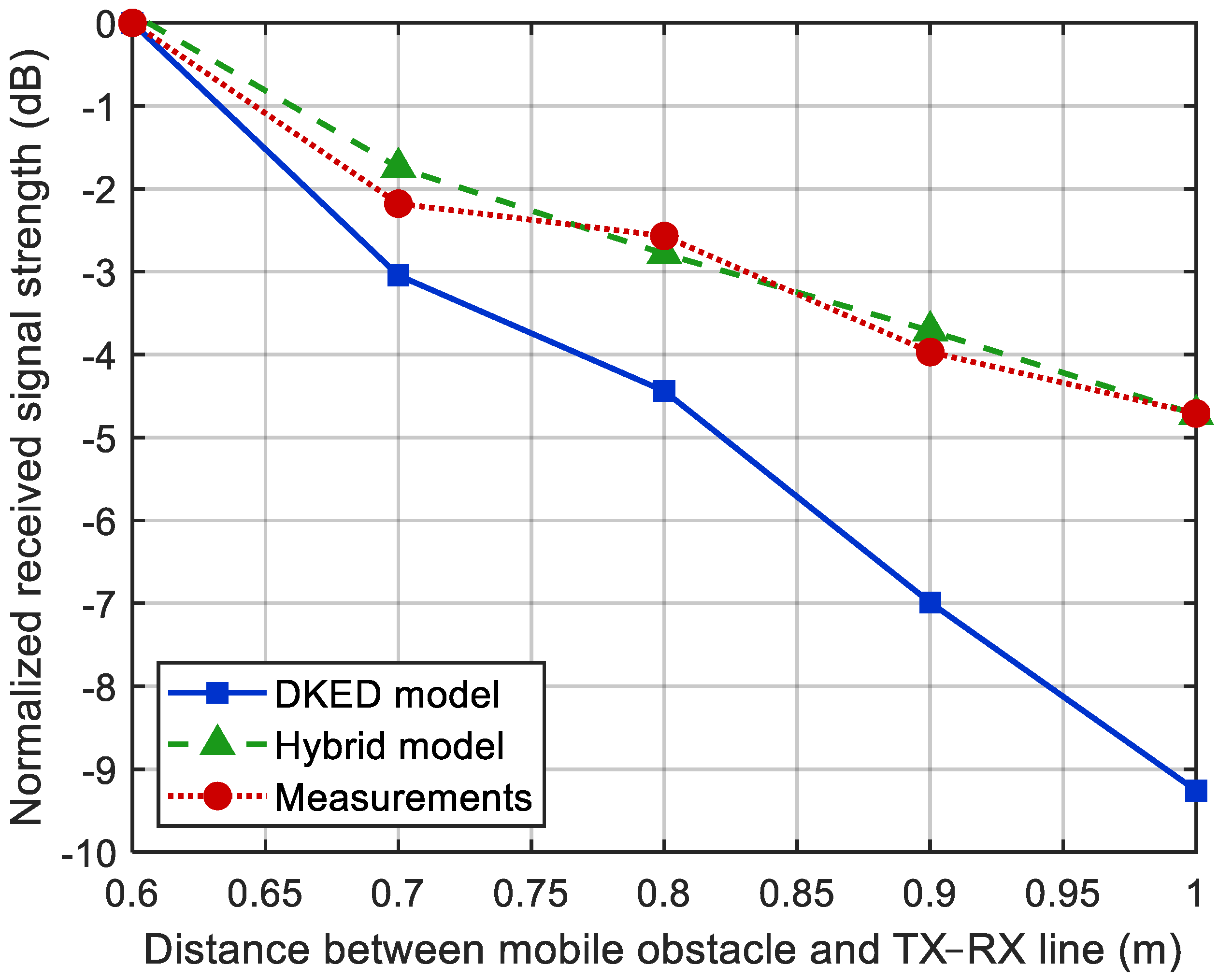
The received signal strength was normalized using the value at 0.6 m as a reference. The attenuation increases with lateral distance, reaching approximately −4.7 dB at 1 m. These trends closely reflect those observed with real human subjects in [11] and are further consistent with empirical measurements of body-blockage attenuation at comparable frequencies reported in [22], supporting the electromagnetic representativeness of humanoids under realistic indoor conditions.

Comparison with the Hybrid Model

Figure 4 compares the simulation output of the hybrid model (green, dashed) with the normalized measurements obtained using humanoid-shaped obstacles (red, dotted). The comparison is performed at five lateral offsets (0.6–1.0 m). Overall, the absolute difference between model predictions and measurements remains below 3 dB for offsets up to 0.7 m from the LOS, demonstrating that the hybrid model captures the dominant propagation behavior near the Tx–Rx line. For offsets beyond 0.8 m, the model slightly overestimates attenuation, with deviations reaching approximately 5 dB at 1.0 m.
These discrepancies can be attributed to several unmodeled factors, including second order reflections, finite-aperture and off-axis effects, and surface roughness. Variations in specular-point visibility on finite humanoid surfaces and polarization effects may also contribute, as documented by Rappaport et al. [10]. These variations fall within uncertainty margins typically observed in indoor propagation models (e.g., ITU-R P.1238-9 [13], 3GPP TR 38.901 [23]).

3.2. Impact of Secondary Reflections

Figure 5 illustrates an enhanced version of the hybrid model which incorporates secondary reflections (i, j), TE Fresnel dependence, and antenna-pattern weighting. The inclusion of these additional phenomena significantly improves the agreement between simulation and measurement, especially at larger lateral offsets where multipath becomes more dominant.
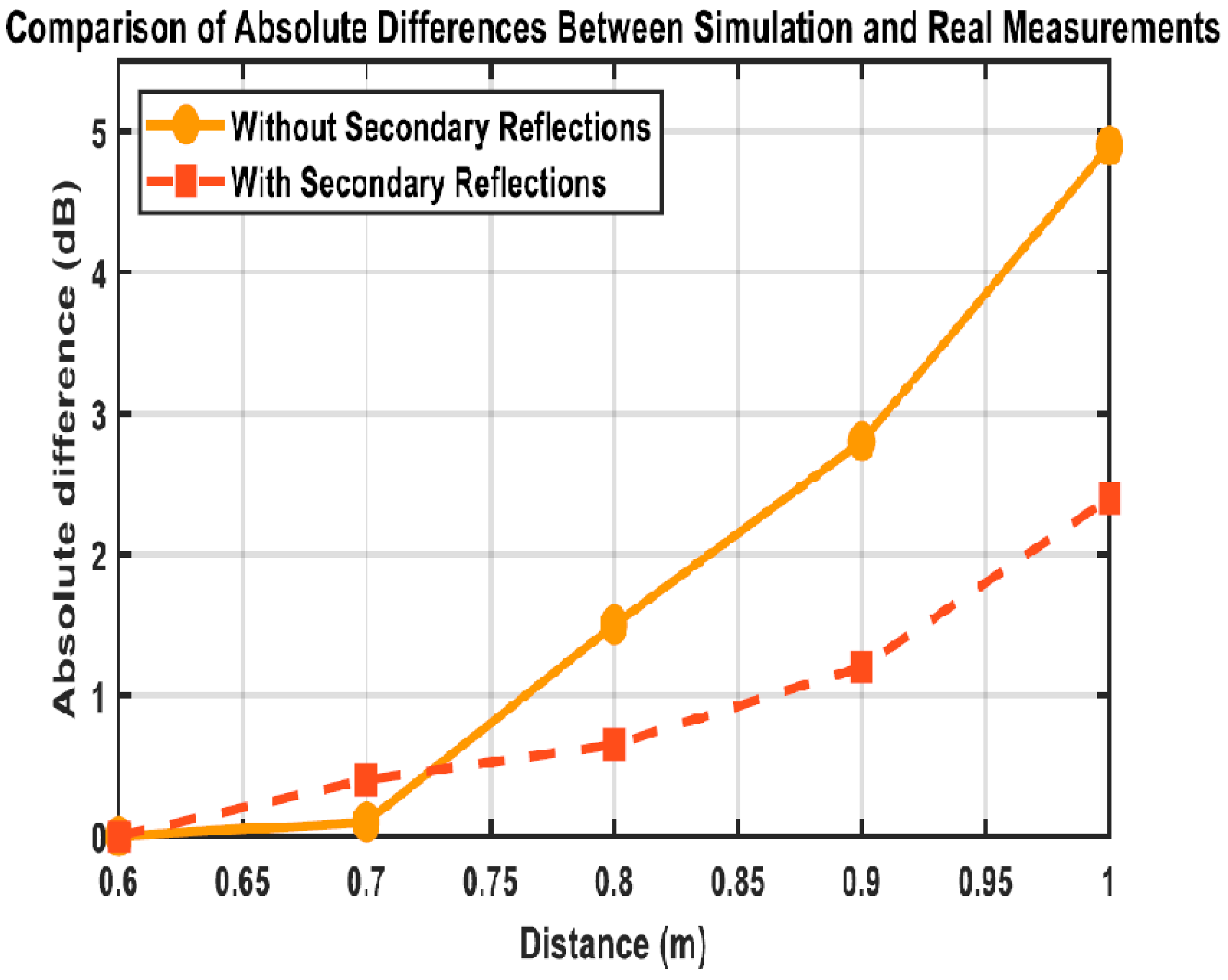
The analysis shows that at 0.7 m, both simulations—with or without secondary reflections (single interaction on each lateral humanoid)—yield small errors (below 0.2 dB), indicating a LOS-dominated regime where diffraction and direct paths suffice. However, beyond 0.8 m, the situation changes significantly as the version of the hybrid model including secondary reflections shows a clear advantage in accuracy. In addition to the qualitative comparison shown in Figure 5, quantitative error metrics were computed between the proposed hybrid model and the measured data overall lateral offsets. The mean absolute error (MAE), root mean square error (RMSE), and maximum absolute error summarized in Table 2, were computed over all lateral offsets using the averaged received-power values, following standard practices for model–measurement comparison in indoor millimeter-wave propagation studies [10].
These error values remain well below typical shadowing and large-scale fading variations reported for indoor millimeter-wave channels, which commonly reach several decibels [7,23]. This confirms that the observed deviations are acceptable for system-level simulations and indoor propagation modeling.
Table 3 provides a quantitative comparison between the relative contribution of reflected paths as a function of reflection order and the deviations observed in the experimental results. While second order reflected paths may exist, their expected contribution is approximately 8 dB lower than the first-order term under the considered geometry and material properties, due to the combined effect of longer propagation paths and additional reflection losses. This places their contribution within the range of residual discrepancies observed in the measurements and typical indoor shadowing variations at 28 GHz, rendering higher-order reflections non-dominant and not reliably isolable within the present experimental setup.

3.3. Absolute Error Evaluation

To quantify this improvement, the absolute error is evaluated as:
abs = P sim   P meas
The error curves in Figure 6 show that at 0.7 m, both model exhibit very small differences (less than 0.2 dB), consistent with scenarios dominated by LOS and first-order paths. Beyond 0.8 m, the enhanced model clearly outperforms the baseline one, highlighting the impact of secondary reflections on accuracy.
Although the improved model substantially reduces error, small residual differences remain, reflecting physical effects not yet modeled, such as higher-order multipath, surface roughness, and dynamic variations. These aspects represent potential directions for further refinement.

4. Discussion

Based on the results obtained from measurements using humanoids as obstacles, these results demonstrate good agreement with the theoretical assumptions underlying the hybrid propagation model. A strong attenuation trend is observed with increasing lateral offset, reflecting the expected transition between direct and dominant first-order paths, as well as scenarios where multipath interactions and edge diffraction become significant. The physical structure of humanoids implies an interaction mechanism that depends on the material used, making it objectively different from that of biological tissues. Thus, structural layers made of the PC/ABS plastic shell and metal exhibit lower absorption and higher reflectivity compared to the human body, which could explain a slight reduction in attenuation for offsets between 0.6 and 0.8 m compared to human data reported in the literature. Nevertheless, it can be observed that the differences remain within the expected margin of uncertainty for existing indoor channel models, indicating that humanoids can be a viable substitute for human-body blocking experiments in a controlled laboratory environment. These observations are consistent with recent analyses of human-body blockage at millimeter-wave frequencies, which highlight significant variability due to body geometry, posture, and angular orientation [24]. Compared to recent works based on stochastic or data-driven approaches, including machine learning techniques combined with random positioning of human structures, machinery, or environment mapping using remote sensing tools, the present study adopts a fundamentally deterministic modeling strategy grounded in ray theory and geometrical theory of diffraction. Although such data-driven approaches have demonstrated strong prediction capabilities in complex environments, they often rely on extensive sensing infrastructure and large-scale datasets, which may limit their applicability in controlled experimental scenarios.
In contrast, while recent sensing-assisted channel modeling approaches exploit images or LiDAR point clouds to infer propagation characteristics from environmental perception [25,26], the proposed framework follows a complementary strategy based on controlled humanoid-induced blockage. This approach enables a physically interpretable and repeatable analysis of diffraction and reflection mechanisms governing indoor millimeter-wave propagation, without requiring external sensing hardware or environment reconstruction. By focusing on dominant propagation paths linking the transmitter and receiver, the proposed model provides a robust baseline for analyzing blockage effects under reproducible laboratory conditions.
In order to further enhance propagation prediction capabilities, future work will consider extending the proposed framework by integrating environment mapping techniques based on remote sensing tools and machine learning approaches. Such extensions would enable more realistic modeling of complex indoor layouts, including the spatial distribution of robots, machinery, and human activity patterns, while preserving the physically grounded nature of the proposed deterministic modeling approach.
In the NLoS configuration involving three humanoid robots, the received signal is primarily governed by diffraction around the central blocker and first-order reflections introduced by the lateral humanoids acting as moving reflective surfaces. This observation explains the increased role of multipath components observed in the following analysis. The inclusion of secondary reflections in the proposed hybrid model is motivated by the need to capture dominant multipath mechanisms that arise in indoor environments when the line-of-sight component is partially or fully obstructed. In the considered NLoS configuration involving multiple humanoid obstacles, first-order reflections from the floor and lateral structures can contribute significantly to the received field, particularly at larger lateral offsets. The adopted modeling approach intentionally limits the reflection order to maintain a balance between physical accuracy and computational simplicity, ensuring that the model remains analytically tractable and suitable for practical indoor channel characterization. The idea of including secondary reflections in the improved formulation leads to a significant improvement in model-measurement agreement, particularly for offsets greater than 0.8 m. At this level, multipath reflections due to the floor and lateral structures can exert a more pronounced influence on the received field. This suggests that complex indoor environments cannot objectively be accurately modeled by diffraction-based approaches alone, and that it would be advantageous to integrate localized Fresnel reflection phenomena and path exclusion based on visibility.
As mentioned in a previous section regarding the methodology, it is important to note that the adopted implementation is limited to 2D lateral movements and assumes a uniform humanoid orientation and posture in the event of obstruction. Effects such as body tilt, limb spacing, surface roughness, polarization-dependent scattering, and temporal motion profiles are not fully modeled. These limitations may open possibilities for extending the model, including the complete 3D modeling of the field’s interaction with the humanoid, the integration of dynamic angular movements, and even the analysis of attenuation statistics, such as the threshold crossing rate and the average attenuation duration. It should be noted that the experimental validation presented in this study is intentionally limited to a single indoor environment, a specific humanoid platform, a fixed link distance, and a carrier frequency of 28 GHz using directional horn antennas. As such, the reported results are not claimed to be universally representative of all humanoid robots or indoor millimeter-wave scenarios. Rather, the proposed framework is intended to demonstrate the physical relevance and reproducibility of humanoid-based blockage modeling under controlled conditions. Variations in humanoid size, shell materials, antenna patterns, operating frequency, and propagation distance are expected to quantitatively affect the attenuation levels, while the underlying diffraction and reflection-driven mechanisms captured by the model are expected to remain qualitatively valid. Future work will focus on extending the proposed framework to account for more complex humanoid dynamics and three-dimensional propagation effects. This includes the investigation of varying humanoid postures, limb configurations, and dynamic motion patterns, as well as the integration of higher-order reflections in more complex indoor environments. Additional measurement campaigns involving different humanoid sizes, surface materials, and antenna configurations will also be considered to further assess the generality of the proposed model.

5. Conclusions

Indoor environments today have become significantly more dynamic, connected, and populated by moving agents. In this context, understanding how humanoid robots interact with millimeter-wave signals becomes not only relevant, but necessary. In this work, we examined a propagation model originally developed for humans and evaluated its applicability to humanoids. Beyond the human-based model, we extended the formulation to include angular effects and secondary reflections This extension was implemented and evaluated within a controlled humanoid-based scenario, demonstrating that the underlying physical mechanisms remain valid when human blockers are replaced by programmable robotic agents. These additions proved useful, especially when humanoids introduce additional dynamism in the environment. Overall, the simulation results match our real-world measurements reasonably well. Although no direct side-by-side measurements with human subjects were conducted in this study, the observed attenuation trends obtained with humanoid robots are consistent with previously reported human-body blockage results, supporting the use of humanoids as controlled and repeatable experimental blockers. The hybrid model showed acceptable agreement with the measured data, although deviations of up to 5 dB were observed at a lateral distance of 1.0 m. These discrepancies indicate that, in its current form, the model does not capture all underlying physical mechanisms, such as secondary reflections, multiple bounces, or mobility-induced effects. Despite these limitations, the model proposed in this work remains a reliable analytical tool for interpreting signal behavior in the presence of moving humanoid obstacles. From an application perspective, the proposed humanoid-based modeling framework is particularly relevant for indoor scenarios such as smart factories, laboratories, and office environments, where robotic agents operate in close proximity to wireless access points and human users. The ability to reproduce blockage dynamics in a controlled and repeatable manner makes the model suitable for link-budget analysis, blockage-aware system evaluation, and robust studies of millimeter-wave indoor links under realistic operating conditions. Extending the model to include higher-order reflections, motion, and more detailed surface descriptions would be a natural continuation toward improving accuracy in future studies.

Author Contributions

Conceptualization, A.D.J.N. and L.T.; methodology, A.D.J.N.; software, A.D.J.N.; validation, A.D.J.N. and V.A.F.; formal analysis, A.D.J.N.; investigation, A.D.J.N.; data curation, A.D.J.N.; writing—original draft preparation, A.D.J.N.; writing—review and editing, L.T. and V.A.F.; supervision, L.T. All authors have read and agreed to the published version of the manuscript.

Funding

This research received no external funding.

Data Availability Statement

The original contributions presented in this study are included in the article. Further inquiries can be directed to the corresponding author.

Acknowledgments

The authors would like to thank the University of Quebec in Outaouais (UQO) for supporting this research. The authors also gratefully acknowledge the technical and engineering staff of the laboratory for their assistance during the experimental setup and measurement campaigns. Language polishing tools were used exclusively for grammar refinement, while all experimental procedures, data acquisition, analysis, and interpretation were fully conducted by the authors.

Conflicts of Interest

The authors declare no conflicts of interest.

Abbreviations

The following abbreviations are used in this manuscript:
DKEDDouble Knife-Edge Diffraction
SCStreet Canyon Model
UTDUniform Theory of Diffraction
LOSLine of Sight
mmWaveMillimeter-Wave
TxTransmitter
RxReceiver
HPBWHalf Power Beamwidth
PC/ABSPolycarbonate/Acrylonitrile Butadiene Styrene
FgeomGeometric Correction Factor
FmatMaterial Correction Factor
FadjAdjustment Factor
VLOSLine-of-sight Visibility Factor
Vii-th Reflector Visibility Factor

References

  1. Tong, Y.; Liu, H.; Zhang, Z. Advancements in Humanoid Robots: A Comprehensive Review and Future Prospects. IEEE/CAA J. Autom. Sin. 2024, 11, 301–328. [Google Scholar] [CrossRef]
  2. Cai, X.; Zhang, G.; Zhang, C.; Fan, W.; Li, J.; Pedersen, G.F. Dynamic Channel Modeling for Indoor Millimeter-Wave Propagation Channels Based on Measurements. IEEE Trans. Commun. 2020, 68, 5878–5891. [Google Scholar] [CrossRef]
  3. Tang, M.; Zhou, B.; Zhong, X.; Liu, X.; Li, Q. Enhanced indoor positioning through human–robot collaboration. Urban Inform. 2024, 3, 7. [Google Scholar] [CrossRef]
  4. Alyosef, A.; Rizou, S.; Zaharis, Z.D.; Lazaridis, P.I.; Nor, A.M.; Fratu, O. A survey on the effects of human blockage on the performance of mmWave communication systems. In Proceedings of the IEEE International Black Sea Conference on Communications and Networking (BlackSeaCom), Sofia, Bulgaria, 6–9 June 2022. [Google Scholar] [CrossRef]
  5. Collonge, S.; Zaharia, G.; El Zein, G. Influence of the human activity on wide-band characteristics of the 60 GHz indoor radio channel. IEEE Trans. Wirel. Commun. 2004, 3, 2396–2406. [Google Scholar] [CrossRef]
  6. Ghaddar, M.; Talbi, L.; Denidni, T. A Conducting Cylinder for Modeling Human Body Presence in Indoor Propagation Channel. IEEE Trans. Antennas Propag. 2007, 55, 3099–3103. [Google Scholar] [CrossRef]
  7. Rappaport, T.S.; MacCartney, G.R.; Samimi, M.K.; Sun, S. Wideband Millimeter-Wave Propagation Measurements and Channel Models for Future Wireless Communication System Design. IEEE Trans. Commun. 2015, 63, 3029–3056. [Google Scholar] [CrossRef]
  8. Fono, V.A.; Talbi, L.; El-Hazari, M. Comparative Study of Three Deterministic Radio Propagation Models in a Complex Media. In Proceedings of the IEEE International Symposium on Antennas and Propagation, USNC/URSI National Radio Science Meeting, Boston, MA, USA, 8–13 July 2018; pp. 1333–1334. [Google Scholar]
  9. Mukherjee, S.; Skidmore, G.; Chawla, T.; Bhardwaj, A.; Gentile, C.; Senic, J. Scalable Modeling of Human Blockage at Millimeter-Wave: A Comparative Analysis of Knife-Edge Diffraction, the Uniform Theory of Diffraction, and Physical Optics Against 60 GHz Channel Measurements. IEEE Access 2022, 10, 121456–121470. [Google Scholar] [CrossRef]
  10. MacCartney, G.R.; Rappaport, T.S.; Sun, S.; Deng, S. Millimeter-Wave Human Blockage at 73 GHz with a Simple DKED Model and Extension for Directional Antennas. In Proceedings of the IEEE Vehicular Technology Conference (VTC-Fall), Montreal, QC, Canada, 18–21 September 2016. [Google Scholar]
  11. Dalveren, Y.; Karatas, G.; Derawi, M.; Kara, A. A Simple Propagation Model to Characterize the Effects of Multiple Human Bodies Blocking Indoor Short-Range Links at 28 GHz. Electronics 2021, 10, 305. [Google Scholar] [CrossRef]
  12. SoftBank Robotics (Formerly Aldebaran). NAO V5 Construction and Material Specifications. Included in the NAO Documentation Package of the Choregraphe 2.x Suite, Internal Technical Manual, 2020. (Manufacturer Documentation). Available online: https://www.scribd.com/document/372884342/NAO-SPECS (accessed on 1 December 2025).
  13. International Telecommunication Union Radiocommunication Sector (ITU-R). Propagation Data and Prediction Methods for the Planning of Indoor Radiocommunication Systems and Radio Local Area Networks in the Frequency Range from 300 MHz to 450 GHz; Recommendation ITU-R P.1238-13; International Telecommunication Union (ITU): Geneva, Switzerland , 2025; Available online: https://www.itu.int/dms_pubrec/itu-r/rec/p/R-REC-P.1238-13-202509-I!!PDF-E.pdf (accessed on 28 November 2025).
  14. Stefanov, S.; Zhekov, G.; Franek, O.; Pedersen, G. Dielectric Properties of Common Building Materials for Ultrawideband Propagation Studies. IEEE Trans. Antennas Propag. 2020, 62, 72–81. [Google Scholar] [CrossRef]
  15. Prado-Álvarez, D.; Inca, S.; Sacristán, D.M.; Monserrat, J.F. Millimeter-Wave Human Blockage Model Enhancements for Directional Antennas and Multiple Blockers. IEEE Commun. Lett. 2021, 25, 2262–2266. [Google Scholar] [CrossRef]
  16. Makris, K.G.; Psaltis, D. Huygens–Fresnel diffraction and evanescent waves. Opt. Commun. 2011, 284, 1686–1689. [Google Scholar] [CrossRef]
  17. Goodman, J.W. Introduction to Fourier Optics, 4th ed.; W. H. Freeman: New York, NY, USA, 2017. [Google Scholar]
  18. Saunders, S.R.; Aragón-Zavala, A. Antennas and Propagation for Wireless Communication Systems, 2nd ed.; Wiley: Chichester, UK, 2007. [Google Scholar]
  19. Orfanidis, S.J. Electromagnetic Waves and Antennas; Rutgers University: New Brunswick, NJ, USA, 2004. [Google Scholar]
  20. Rodriguez-Cano, R.; Perini, S.; Lanagan, M.T. Dielectric Characterization of Materials at 5G mm-Wave Frequencies. In Proceedings of the 18th European Conference on Antennas and Propagation (EuCAP), Glasgow, UK, 17–22 March 2024. [Google Scholar] [CrossRef]
  21. Correll, N.; Dutta, P.; Han, R.; Pister, K. Wireless Robotic Materials. In Proceedings of the 15th ACM Conference on Embedded Networked Sensor Systems (SenSys ’17), Delft, The Netherlands, 6–8 November 2017; Association for Computing Machinery: New York, NY, USA, 2017; pp. 1–6. [Google Scholar] [CrossRef]
  22. Zhao, X.; Wang, Q.; Li, S.; Geng, S.; Wang, M.; Sun, S.; Wen, Z. Attenuation by Human Bodies at 26 and 39.5 GHz. IEEE Antennas Wirel. Propag. Lett. 2016, 16, 1229–1232. [Google Scholar] [CrossRef]
  23. 3rd Generation Partnership Project (3GPP). Study on Channel Model for Frequencies from 0.5 to 100 GHz; 3GPP Technical Report TR 38.901 V17.0.0; European Telecommunications Standards Institute: Valbonne–Sophia Antipolis, France, 2023. [Google Scholar]
  24. Virk, U.T.; Haneda, K. Modeling Human Blockage at 5G Millimeter-Wave Frequencies. IEEE Trans. Antennas Propag. 2020, 68, 2256–2266. [Google Scholar] [CrossRef]
  25. Wang, C.; Ai, B.; He, R.; Yang, M.; Zhou, S.; Yu, L.; Zhang, Y.; Qiu, Z.; Zhong, Z.; Fan, J. Channel Path Loss Prediction Using Satellite Images: A Deep Learning Approach. IEEE Trans. Mach. Learn. Commun. Netw. 2024, 2, 1357–1368. [Google Scholar] [CrossRef]
  26. Huang, Z.; Bai, L.; Sun, M.; Cheng, X. A LiDAR-Aided Channel Model for Vehicular Intelligent Sensing–Communication Integration. IEEE Trans. Intell. Transp. Syst. 2024, 25, 20105–20119. [Google Scholar] [CrossRef]
Figure 1. Indoor measurement scenario involving three humanoids positioned on a calibrated grid. The central humanoid represents the main line-of-sight (LOS) blocker, while the two lateral humanoids emulate moving obstacles following predefined lateral trajectories toward the LOS in discrete position increments at different distances.
Telecom 07 00017 g001
Figure 2. Top view of the double knife-edge diffraction (DKED) model, illustrating a static humanoid blocking the line-of-sight (LOS). Solid lines indicate the incident and diffracted propagation paths, dashed lines represent shadow region boundaries, and different colors are used to distinguish illuminated and shadowed areas. The vectors E A and E B denote the diffracted electric field contributions associated with the upper and lower knife edges, respectively.
Telecom 07 00017 g002
Figure 3. Top-view representation of the hybrid propagation model, combining DKED from the central opaque humanoid with Street-Canyon specular reflections from the lateral humanoids. Solid lines represent diffraction paths associated with the central humanoid (DKED component), while colored oblique paths indicate specular reflections from the lateral humanoids following the Street Canyon model. Different colors are used to distinguish the main propagation mechanisms and interaction points.
Telecom 07 00017 g003
Figure 4. Normalized received signal strength as a function of lateral distance for humanoid obstacles: measured values (red, dotted), DKED-based model (blue, solid), and hybrid model including specular reflections (green, dashed).
Telecom 07 00017 g004
Figure 5. Comparison between measured data and hybrid model simulations with and without inclusion of secondary reflections (street-canyon components).
Telecom 07 00017 g005
Figure 6. Absolute error between simulation models and experimental measurements, with and without inclusion of secondary reflections.
Telecom 07 00017 g006
Table 1. Summary of parameters used in the hybrid DKED–Street-Canyon propagation model.
SymbolDescriptionPhysical MeaningPose Dependency
E LOS Line-of-sight fieldDirect Tx–Rx contributionNo
E A , E B Diffracted fieldsKnife-edge diffraction from central humanoid edgesWeak
F geom Geometric obliquity factorAccounts for Tx/Rx incidence anglesYes
F mat Material correction factorAccounts for humanoid shell material (PC/ABS)Weak
F adj DKED adjustment factorCombined geometric and material correctionWeak
E c Complex relative permittivityElectromagnetic property of humanoid shellNo
αAttenuation coefficientLoss inside the humanoid shell materialNo
βPhase coefficientPhase delay inside the materialNo
Effective material path lengthThickness-dependent propagation pathYes
V i Visibility indicatorDetermines existence of specular pathYes
Γ i TE Fresnel reflection coefficientSpecular reflection from lateral humanoidYes
r i Specular path lengthTotal reflected propagation distanceYes
Note: The formulation and calibration are based on a standing neutral humanoid posture with fixed limb configuration. Variations in pose primarily affect geometric and visibility-related parameters. Also, for readability, vector notation is omitted in Table 1; the corresponding quantities are treated as vector electric fields in the analytical formulation.
Table 2. Quantitative error metrics between measurements and hybrid model predictions.
MetricValue (dB)
Mean Absolute Error (MAE)0.16
Root Mean Square Error (RMSE)0.22
Maximum Absolute Error0.30
Table 3. Quantitative comparison of reflected-path contributions and experimental deviations.
Reflection OrderF_Mat
(Material Factor)
F_Geom
(Geometric Factor)
Relative
Contribution (dB)
Observed
Deviation in Results
1|Γ|2(L1/L1)2 = 10 dB (reference)MAE ≈ 0.16 dB, RMSE ≈ 0.22 dB
2|Γ|4 ≤ 0.25(2.0/2.5)2 ≈ 0.64≈−8 dBResidual deviation up to ≈5 dB at 1.0 m
3|Γ|6 ≤ 0.0625<(2.0/2.8)2<−14 dBBelow dominant contribution
Disclaimer/Publisher’s Note: The statements, opinions and data contained in all publications are solely those of the individual author(s) and contributor(s) and not of MDPI and/or the editor(s). MDPI and/or the editor(s) disclaim responsibility for any injury to people or property resulting from any ideas, methods, instructions or products referred to in the content.