Article

Initial Synchronization Procedure and Doppler Pre-Compensation for LEO-SATCOM Terminals

HTWK Leipzig, University of Applied Science, Faculty of Engineering, 04277 Leipzig, Germany
Telecom 2025, 6(4), 81; https://doi.org/10.3390/telecom6040081
Submission received: 4 September 2025 / Revised: 3 October 2025 / Accepted: 10 October 2025 / Published: 21 October 2025

Abstract

Wireless low earth orbit (LEO) satellite communication ground terminals need to perform an initial time and frequency synchronization to access to the LEO system. Initial synchronization consists of three steps: detecting the presence of the LEO satellite downlink signal, synchronizing the terminal receiver to the current Doppler frequency shift and performing Doppler pre-compensation before uplink signal transmission, and ensuring low probability of false alarm at low SNR in the LEO uplink receiver. This article explains this three step synchronization procedure in detail. The major advantage is that the synchronization procedure can be carried out even without a priori knowledge of the satellite orbit ephemeris or any sort of GNSS navigation data. Initial synchronization is of particular importance for typical LEO uplink signals which are formed of short radio bursts. The packet detection in burst traffic radio systems is a crucial task to accomplish start of frame detection. It triggers the start of the digital receiver algorithms to demodulate the incoming uplink burst. The packet detection is accomplished by cross-correlation and threshold detection which show significant probability of false alarm in low signal to noise (SNR) regions. Hence, before running a stable uplink connection, the terminal must accomplish the proposed initial synchronization procedure, as outlined in this article.

1. Introduction

Recent low earth orbit (LEO) satellite systems often use multi-frequency time division multiple access (MF-TDMA) or orthogonal frequency division multiple access (OFDMA) 4G LTE-like wave forms in the uplink. This requires accurate time and frequency synchronization on the ground terminal side as explained in [1,2]. Even in the context of satellite internet of things (IoT) systems such as those presented in [3], precise time and frequency synchronization must be established for coherent signal demodulation. This paper explains a three step approach for initial LEO ground terminal time and frequency synchronization in the following LEO satellite scenario:
  • It is assumed that only one LEO satellite is in range. Even in a multi-satellite (constellation) scenario, we assume that one ground terminal is transmitting to only one dedicated LEO satellite at a time. This appears to be an unrealistic assumption. However, it can be easily achieved through directional ground terminal antennas. Here spatial orthogonality is applied. Alternatively, all uplink and downlink signals associated with multiple satellites are assumed to be frequency orthogonal, which avoids inter-satellite interference.
  • The LEO uses a regenerative payload. The frequency bands of interest are Ku and Ka bands.
  • The LEO transmits a continuous downlink (DL) carrier, which is M-QAM (M-ary quadrature modulation) or M-PSK (M-ary phase shift keying) modulated.
  • The LEO antenna beam used for uplink (UL) reception and downlink signal transmission is assumed to be circular shaped and nadir-pointed. We are assuming that the swath diameter on the earth is large, i.e., in the order of 500–1000 km, depending on orbit height.
  • Due to the wide antenna swath, no a priori Doppler frequency compensation is applied in the LEO satellite. Hence, each ground terminal needs to perform its own Doppler compensation.
  • The ground terminal implements a broadband wireless access scenario in the uplink, having signal bandwidth in the order of 5 up to 30 MHz. The terminals initial network log-on, however, is realized by means of a narrow band random access channel (RACH), which uses ALOHA-like [4] log-on radio bursts. It is assumed that the RACH uses a dedicated frequency band, which is not used by regular uplink payload data transmission. The initial log-on bursts only have a maximum signal bandwidth of up to 100 kHz. Hence, the RACH reception is rather sensitive to Doppler frequency shifts which motivates us to pre-compensate Doppler effects in the ground terminals.
  • Since the LEO overflight time is limited, the ground terminal tries to maximize the useful transmission time. Hence, the terminals will start the initial Doppler frequency synchronization and pre-compensation at an early stage of the LEO overflight, where even the DL signal is still not decodable. This motivates us to use blind DL carrier detection and Doppler pre-compensation algorithms, which do not rely on the decodability of the DL carrier.

1.1. Preliminary Work and Contribution

Numerous work has been carried out for blind and data-aided Doppler frequency offset estimation and synchronization such as in [5,6,7,8]. The proposed algorithms work well at signal to noise ratios (SNR) which allow DL carrier demodulation and decoding. However, our scope is to provide Doppler frequency synchronization and pre-compensation even earlier where DL signal demodulation is still not possible.
Authors in [9] refer to critical local oscillator drift compensation without mentioning the operating SNR. Reference [10] describes Doppler frequency shift estimation at low SNR (<−3 dB) using multiple receive antennas at the ground terminal side. In this paper, however, we do not assume multiple receive antennas at the ground terminal side. Our approaches even work with a single ground terminal antenna. In [11,12], the authors describe Doppler tracking algorithms for satellite applications at moderate or even high signal to noise ratios. However, despite the large amount of research in the literature on Doppler estimation and pre-compensation, we like to provide a coherent description of the entire initial synchronization procedure for LEO ground terminals. We explicitly avoid any a priori knowledge of GNSS-based time/location data, which could simplify the synchronization process. Our aim is to address such scenarios, where GNSS data is unavailable—either due to device failure or due to GNSS jamming/spoofing.
Finally, we like to mention the fact that the proposed blind carrier detection and Doppler estimation schemes will add extra complexity to the receiver. This complexity increase needs to be handled with care in the final receiver design.

1.2. Introduction into the Three Step Approach

At an early stage of the LEO overflight where the link budget is still too weak to perform downlink and uplink data communication, the ground terminal must perform a number of initial synchronization steps. This involves the following three steps, which are ordered according to the uplink and downlink SNR γ :
  • −10 dB γ −3 dB: detect the presence of the LEO satellite downlink signal.
  • −3 dB γ 0 dB: synchronize the terminal receiver to the current Doppler frequency shift, perform Doppler pre-compensation before uplink signal transmission.
  • 0 dB γ 3 dB: ensure a low probability of false alarm at LEO uplink packet detection.
The selection of the SNR regions may appear quite arbitrary. However, it is justified by the MODCOD (modulation and coding) schemes as used in DVB-S2x (Digital Video Broadcasting-Satellite 2x) and DVB-RCS2 (Digital Video Broadcasting-Return Channel Satellite 2) systems. Here, an SNR of 0 dB is used as a threshold, where stable signal transmission is possible.

1.2.1. Step 1: Downlink Carrier Detection

MF-TDMA frequency-slot and time-slot assignment are centrally coordinated by the LEO system and are propagated continuously in the LEO downlink signal as defined in the DVB-RCS2 standard [13]. Similar techniques are applied in the OFDMA-based non-terrestrial networks. The LEO transmits a continuous downlink carrier, which is M-QAM or M-PSK modulated. DVB-S2x is a well-known example of such a continuous DL signal type. The ground terminals a priori know the modulation format (BPSK, QPSK, 8-PSK etc.) of the DL carrier. The LEO DL signal is decodable at all ground terminals and serves as a beacon signal for the initial synchronization procedure. This procedure is required before the terminal enters the MF-TDMA/OFDMA uplink system in order not to harm other uplink users. The initial terminal synchronization procedure starts if the LEO satellite overflight is in an early phase, where even the DL is still not decodable. The aim of the first step is to detect the presence of the LEO downlink signal, which triggers the wake up of the digital ground terminal TRx (transmitter-receiver). In addition, our aim is to estimate the downlink SNR γ D L at this early phase of the LEO overflight without using a priori knowledge of orbit ephemeris data or the GNSS information. If the downlink SNR γ D L approaches a certain level, the second step of the initial synchronization procedure is triggered.

1.2.2. Step 2: Doppler Pre-Compensation

To establish an uplink connection between the ground terminal and the LEO satellite, the Doppler shift between the terminal and LEO must be pre-compensated. This is because MF-TDMA or OFDMA preserves signal orthogonality by means of dedicated sub-channel or sub-band allocation. Strong Doppler shift can potentially harm signal orthogonality especially in narrow band carriers. Moreover, Doppler-pre-compensation is required because a strong Doppler shift harms the uplink packet detection. Any Doppler shift reduces the uplink signal preamble cross-correlation metric and, hence, needs to be pre-compensated at the ground terminal. Moreover, the cross-correlator of the LEO uplink packet detector uses a given threshold to declare packet reception. We are proposing a set of blind signal detection and blind carrier frequency offset estimation algorithms, which shall be used to pre-compensate the uplink Doppler shift. Moreover, our proposal allows triggering the actual start of the uplink data transmission, which is based on blind estimation of γ D L . In addition, this second step of the initial synchronization procedure triggers the beam acquisition of phased array ground terminal antenna as described in [14], which is, however, out of scope in this article.

1.2.3. Step 3: Reduction of False Alarms in UL LEO Receiver

The bursty nature of MF-TDMA radio signals requires the implementation of packet detection. Moreover, burst traffic radio systems are of high relevance for LEO satellite communications and satellite IoT systems [15]. In particular, the ICARUS (international cooperation for animal research using space) animal observation system [3] uses short uplink bursts for IoT sensor data transmission. The uplink signal is modulated in the form of fixed size symbol sequences, so called radio frames (bursts). The packet detection is used to estimate the start time instant of a received radio frame, which is often realized by means of cross-correlation techniques. The digital receiver performs a cross-correlation of the incoming symbol stream with the copy of the preamble sequence. In low SNR at the beginning of the LEO overflight, there is a high probability of false alarm (FA), which generates strong blocking of the receiver with noise instead of valid incoming uplink packets. Hence, our motivation is to develop a FA prevention scheme entitled Preamble Sub-Sequence Coding as part of the entire initial synchronization procedure. The aim of the preamble sub-sequence coding is to detect the false alarm event and to stop the running receiver immediately to avoid receiver blocking. Instead of falsely processing noise, this will turn the receiver back into idle mode, where it is again ready to detect incoming uplink packets.

1.3. Article Structure

This article is structured as follows: In Section 2, we define the baseband signal model used to describe the downlink and uplink signals. In Section 2, we also describe the blind DL signal detection. Section 3 explains the algorithms used for blind Doppler shift estimation and uplink signal Doppler pre-compensation. In Section 4, we explain the new concept of Preamble Sub-Sequence Coding. We provide conclusions of this study in Section 5.

2. Doppler Effect and Baseband Signal Model and Downlink Carrier Detection

2.1. Baseband Signal Model and Doppler Effect

The Doppler effect induces two sorts of distortion effects on the baseband signal: time-varying phase rotation and sample/symbol clock error due to signal compression/dilation. The Doppler frequency shift causes a frequency offset (CFO) between the transmitter and the receiver. This time-varying CFO is defined as ν ( t ) when using the non-relativistic Doppler equation:
ν ( t ) = f c v o r b i t c cos ( α ( t ) ) ,
where f c , c and v o r b i t define the transmitter carrier frequency, speed of light, and LEO orbit velocity, respectively. The angle α ( t ) denotes the time-varying angular difference between the terminal and LEO velocity vectors. The first derivative of ν ( t ) is called the Doppler rate r d :
r d ( t ) = d ν ( t ) d t .
We consider a sampled baseband receiving signal y [ k ] , where the sample index k represents the time instant k T s . Here, T s denotes the signal sampling time, and f s = 1 / T s represents the sample rate. We assume that the receiver applies an integer oversampling ratio N o s as follows:
T s y m = N o s T s and f s = N o s f s y m ,
where T s y m and f s y m = 1 / T s y m denotes the symbol time duration and the symbol rate of the transmitted complex M-QAM data symbols x. The Doppler shift generates a time compression/dilation of the received signal. This compression/dilation effect causes a sample clock error Δ T s of the received signal according to the following rule:
Δ T s = ν f c T s .
In this article, we will ignore the sample clock error Δ T s because it is not relevant for the proposed initial synchronization procedure. This is because Δ T s is independent from the carrier frequency, where Δ T s / T s 2.5 × 10 5 for 400 km orbit height, which is fairly low. The time-varying phase rotation of the received signal y [ k ] , however, must be considered. Therefore, we further assume ν to be normalized to the sample rate:
y [ k ] = x [ k ] h e j 2 π ( ν + 0.5 r d k ) k + n [ k ] .
Here, x [ k ] denotes the complex transmit signal, h is the slowly fading complex-valued channel coefficient, and n [ k ] represents the additive complex Gaussian noise. The SNR γ is defined as follows
γ = h 2 σ x 2 σ n 2
where σ x 2 and σ n 2 represent signal and noise power, respectively.
The Doppler pre-compensation works only if the carrier frequency offset in the uplink and downlink is dominated by a Doppler shift where oscillator inaccuracies play a minor role. This is often the case in the Ku-Band and Ka-Band systems, as outlined in Table 1.

2.2. Blind Downlink Carrier Detection

The LEO satellite ground terminal requires a simple mechanism to detect the presence of the DL carrier in order to trigger the initial synchronization procedure. The LEO DL signal detection shall work blindly, i.e., it only shall use simple a priori knowledge of the DL carrier signal properties such as the symbol rate and the downlink carrier frequency. It shall also work at low SNR at which the DL carrier is often not decodable.
Our proposal is to exploit the properties of root-raised cosine (RRC) pulse shaped M-QAM carriers according to [16]. The squared magnitude of x [ k ] is transformed in the frequency domain by means of discrete time Fourier transform (DTFT), which yields X c ( f ) :
X c ( f ) = k = 0 K 1 x [ k ] 2 e j 2 π k T s f .
Note that no a priori knowledge of the modulation format (e.g., BPSK, QPSK, 64-QAM etc.) is required as outlined in [16]. If N o s > 1 the spectrum X c ( f ) shows a spectral line at exactly the same rate as the symbol rate f s y m . Figure 1 shows X c ( f ) 2 for a RRC pulse shaped QPSK signal with N o s = 5 . One can easily see the spectral lines at the symbol rate. We propose to realize the DTFT operation by means of discrete Fourier transform (DFT) and only calculate two bins: one at exactly f 1 = f s y m and one neighboring DFT bin at f 2 = f s y m + Δ f . Here, Δ f denotes the frequency difference between bins f 1 and f 2 , which is used to realize a peak detection of the symbol rate spectral line depicted in Figure 1. In practice, we recommend Δ f 0.02 f s y m . This two-bin DFT architecture is depicted in Figure 2. Please note that the two-bin approach is a heuristic which reduces the entire spectrum X c ( f ) to only two complex numbers. This saves computational resources at the receiver side. In practical systems, this heuristic shows robust results even at low SNR as depicted in Figure 3.
The proposed circuit generates a receiver signal strength indicator (RSSI) metric, which is proportional to γ D L , as depicted in Figure 3. More precisely, the RSSI metric can be considered as a bijective function in the γ D L domain and hence can be used for DL SNR estimation through a simple look-up table mapping approach.

3. Blind Doppler Shift Estimation and Doppler Pre-Compensation

3.1. Blind Doppler Shift Estimation

After the presence of the DL carrier is detected, the second step of the initial terminal synchronization procedure is triggered. This second step is blind Doppler shift estimation, which uses the following receive signal transformation which is based on the M-power algorithm reported in [17]:
y M [ k ] = y [ k ] M
where M denotes the size of the symbol alphabet of the M-QAM modulation format used in x [ k ] . For QPSK M = 4, whereas for 8-PSK M = 8, and so forth. Note that the method also works for higher-order modulation (e.g., 64-QAM etc.), which then requires higher SNR values. There are two possible modes of operation as follows:
  • In the early phase of the LEO satellite overflight only BPSK or QPSK are used and M value can be fixed.
  • Downlink adaptive coding and modulation (ACM) is used where M might change over time. In such a case, parallel blind estimators are applied, each having a given M value. An additional logic then combines the individual CFO estimation results.
Ignoring noise n [ k ] and r d for now, the power of M operation will yield the following:
y M [ k ] x [ k ] M e j 2 π ( M ν ) k ,
where x [ k ] M = 1 at the symbol time instants for BPSK, QPSK, and 8-PSK. Using this property, we can approximate y M [ k ] as a complex harmonic of frequency M ν . Using a fast Fourier transformation (FFT) operation will yield the discrete spectrum Y M [ m ] of y M [ k ] as follows:
Y M [ m ] = k = 0 K 1 y M [ k ] e j 2 π m k K ,
where the m-th FFT bin represents the discrete frequency f = m f s K , where the index m is defined in the interval [ K / 2 : K / 2 1 ] . The Doppler frequency shift ν can now be estimated by the following equation:
ν ^ = f m a x M with f m a x = m m a x f s K ,
where
m m a x = arg max m Y M [ m ] 2 .
Figure 4 shows the principal FFT based blind Doppler estimation scheme. Satisfying results can be reached if multiple single FFT spectra Y M [ m ] 2 are averaged before a maximum search according to Equation (12). Figure 5 shows that the blind Doppler estimation yields reliable results at γ D L 3 dB . Using FFT-based estimation generates a maximum Doppler estimation error Δ ν m a x , which is determined by the FFT size K as follows:
Δ ν m a x = N o s f s y m 2 K = f s 2 K .
Please note that Equation (11) estimates the downlink Doppler shift ν ^ = ν ^ D L . Doppler pre-compensation, however, must be carried out at uplink (UL) center frequency f c , U L . Hence, based on Equation (1), we need to scale the downlink Doppler estimation to the uplink center frequency as follows:
ν ^ U L = f c , U L f c , D L ν ^ D L .
In this research, we inherently assumed that the UL-DL scaling were used according to Equation (14). Hence, for sake of simplicity, we write ν ^ to denote the uplink Doppler shift estimation.

3.2. Doppler Pre-Compensation

In LEO satellite systems, the Doppler shift must be pre-compensated at the ground terminal before transmitting the uplink signal. It ensures that even narrow-band uplink frames are received correctly. Let’s consider an uplink signal with symbol rate f s y m = 0.5 MHz. According to Table 1, this uplink signal is received by the satellite with a Doppler shift of ν 200 kHz, when transmitted in the Ku-Band (between 10–12 GHz). This would result in a normalized Doppler shift of ν 40 % , which often cannot be captured or corrected by the LEO receiver. Hence, Doppler pre-compensation must be carried out symbol-wise at the ground terminal as follows:
x [ k ] = x [ k ] e j 2 π ( ν ^ [ k ] ) k ,
where ν ^ [ k ] denotes the estimated time-varying Doppler shift at symbol time instant k. The drawback of the proposed blind Doppler estimation is, however, that it provides estimates ν ^ block-wise, i.e., with a given latency of K samples. Hence, we need to interpolate ν ^ [ k ] at symbol clock from block-wise estimates ν ^ . For interpolation, we propose a simple Doppler tracking loop according to Figure 6.
Here, the Doppler shift ν ^ [ k ] is tracked recursively, using the estimate r ^ d of the Doppler rate:
ν ^ [ k ] = ν ^ [ k 1 ] + r ^ d [ k 1 ] T s y m .
Whenever a new Doppler shift estimation ν ^ is provided by the blind estimator, the loop variables are updated as follows:
ϵ = ν ^ [ k 1 ] ν ^ ,
where the two loop parameters k p and k i are used as the following:
ν ^ [ k ] = ν ^ [ k 1 ] k p ϵ + r ^ d [ k 1 ] T s y m ,
r ^ d [ k ] = r ^ d [ k 1 ] k i ϵ .

3.3. Example Scenario

We illustrate the tracking-loop based Doppler pre-compensation with example parameters summarized in Table 2. The blind Doppler estimation is simulated by generating
ν ^ = ν + Δ ν ,
where the Doppler estimation error Δ ν is an equally distributed random variable in the interval [ Δ ν m a x : Δ ν m a x ] .
Figure 7 and Figure 8 illustrate example trajectories of the Doppler rate loop register r ^ d and the Doppler shift tracking error Δ ν normalized to the symbol rate. These results are referring to the simulation parameters given in Table 2. It is evident that the Doppler tracking converges after 8–10 s. This implies that the terminal is able to start payload or RACH signal transmission after this amount of time. This time duration (8–10 s) can be regarded as a typical value for LEO overflight scenarios in which the downlink SNR is still not high enough for regular downlink signal decoding. It strongly depends on the LEO orbit height and the LEO antenna patterns.

4. False Alarm Prevention in Uplink Packet Detection

This section explains the false alarm prevention algorithm, which shall be used in the early phase of the LEO satellite overflight, where the SNR is still low.

4.1. The Receiver Operating Characteristics

The bursty nature of various MF-TDMA uplink signals requires the implementation of packet detection. The packet detection is widely used in terrestrial wireless communications, such as Wifi IEEE 802.11a/n [18] or Long Range Wide Area Network (LoRaWAN) [19]. The packet detection is used to estimate the start time instant of a received radio frame, which is often realized by means of cross-correlation techniques. The digital receiver performs a cross-correlation of the incoming symbol stream with the copy of the frame preamble sequence of length L. Figure 9 shows a typical tapped delay line architecture used for cross-correlation [20].
The cross-correlator implements the following equation to obtain the correlation metric m [ k ] :
m [ k ] = 1 L l = 0 L 1 y [ k l ] x p * [ L l 1 ] .
Let’s define the burst start time instant k 0 at which the preamble sequence x p is fully received. The aim of the packet detector is to detect the cross-correlation metric m [ k 0 ] at the threshold detector as follows:
m [ k 0 ] 2 T ,
where T represents the given threshold. Notably, | m [ k 0 ] | 2 depends on the CFO and the sequence length, as follows reducing correlation peaks at certain CFO values. For bi-polar PN-sequences (pseudo-noise sequences), the following degradation holds:
| m [ k 0 ] | 2 1 L l = 0 L 1 e j 2 π ν l 2 .
The cross-correlator output is power-normalized, as described in [20] and then, fed to a threshold detector. A start of frame is declared, if the correlation metric exceeds the given threshold T, which impacts two important probabilities: the miss detection probability P m i s s and The probability of false alarm P F A .
The threshold detector declares a valid burst start if the cross-correlation metric exceeds a given threshold T. In this respect, the threshold must be optimized according to the following targets:
  • The threshold shall be high enough to avoid random noise to trigger a burst detection event. This would result in a so-called false alarm, where P F A denotes the probability of false alarm accordingly.
  • The threshold shall be low enough to ensure that even weak cross-correlation peaks of the incoming preamble sequence are still being detected. If the threshold detector misses a valid packet start, this results in a miss-detection event. The miss detection probability represents variable P m i s s .
Hence, the system designer needs to define the threshold T such that it achieves a viable compromise between the probability of false alarm and the probability of miss-detection. In receiver operating characteristics (ROC), both probabilities are displayed in one diagram as shown in Figure 10.
The probability of miss detection P m i s s depends on the probability density function (PDF) of | m [ k 0 ] | 2 , i.e., at the ideal burst start time instant k 0 . Hence, we define f M , k 0 ( m ) as the PDF of the random variable | m [ k 0 ] | 2 accordingly from which we can calculate P m i s s by
P m i s s = T T f M , k 0 ( m ) d m .
The probability of false alarm P F A in turn depends on the PDF of | m [ k ] | 2 in the case where only noise n [ k ] is received. In this case we define the PDF of | m [ k ] | 2 by f M , n ( m ) from which we can calculate P F A as follows:
P F A = 1 T T f M , n ( m ) d m .
Many authors such as [21] model the random variable | m [ k 0 ] | as Ricean distributed, which allows closed form solutions of Equation (24) and Equation (25). The literature shows that both P m i s s and P F A are becoming lower with increasing preamble length as long as CFO is not the limiting factor.
If T is set low, P m i s s is low because even small correlation metric values will lead to a frame start detection. However, if T is set low, P F A becomes high because frame start events are falsely detected even when only noise is sampled. For more fundamental details on cross-correlator based packet detection, we recommend reading [22]. In practice, the high-false-alarm probability P F A congests the receiver chain with falsely received frames. This blocks the payload frame reception if not properly handled. The trade-off between T, P m i s s and P F A is illustrated as ROC [23] in Figure 10. In this example, a L = 63 BPSK PN-sequence is used as preamble. The ROC is measured at an SNR of 0 dB.
The ROC in Figure 10 shows that a threshold T = 0.15 must be used to achieve P m i s s = 3 × 10 7 at the cost of a fairly high false alarm probability of P F A = 7 × 10 5 . Obviously, any further reduction of P m i s s will prohibitively increase P F A even further. If SNR is higher, the situation becomes better. At moderate SNR values > 3 dB, the threshold is often set higher, reducing P F A .
Let’s assume a symbol rate of f s y m = 1 MHz and a burst length of 10 4 symbols, which are typical values for LEO satellite and satellite IoT applications. When evaluating Figure 10, the blocking probability can be derived as listed in Table 3.
Especially in low SNR regions (<3 dB), the false alarm rate leads to significant receiver blocking where almost 10% of the time, the receiver is blocked by false alarm events. When being blocked, all incoming radio frames are not processed, which leads to high packet loss rates due to FA events. Receiver blocking due to false alarm events could be mitigated by means of extra backup receiver capabilities in the LEO satellite. Since these extra processing capabilities are not always present in the LEO receiver, we consider receiver blocking to be a critical system impairment, which needs to be avoided.
An increase of the preamble length L might reduce P F A to an acceptable level. This option, however, is not of practical relevance because the frame format and preamble length are given parameters, defined in the signal specification of the corresponding radio standard. Hence, our motivation is to develop a novel FA prevention scheme that only relies on the existing frame structure.

4.2. FA Prevention

FA Prevention (FAP) can be accomplished by a PHY header field cyclic redundancy check (CRC) as carried out in DVB-S2 [24]. In most practical cases, however, such a PHY header CRC protection is simply not part of the radio standard, which necessitates an alternative FAP scheme. Hence, we, firstly, introduce a typical frame structure of burst traffic radio frames. Then, we explain the simple but yet impractical concept of using a separate FA prevention field that could be used to detect FA events. Using a separate data field only for false alarm detection is impractical because it scarifies the spectral efficiency of the UL data burst. However, we explicitly explain the usage of such a separate FA detection data field because it provides the fundamental idea behind the proposed preamble sub-sequence coding scheme. Finally, we explain how to perform FA detection without using a separate data field by using the proposed preamble sub-sequence coding. Preamble sub-sequence coding uses the yet existing preamble sequence, which is used for false alarm detection. Hence, the proposed preamble sub-sequence coding does not impose additional signaling overhead while embedding FA detection. Moreover, preamble sub-sequence coding allows implementing the FA detection even in cases where the signal structure, consisting of pre-determined preamble and signaling fields, cannot be changed any more (as the case of radio receivers, which implement a given radio standard).

4.2.1. Burst Traffic Frame Structure

A typical radio burst consists of a preamble and a short PHY (physical layer) header. The preamble is used for packet detection, whereas the PHY base band (BB) header encodes the MODCOD used inside the frame. Figure 11 shows such a typical structure.
Without loss of generality, we are assuming a binary phase shift keying (BPSK) modulation used for the preamble sequence as follows:
x [ k ] = 1 , 1 k = 0 L 1 .

4.2.2. FA Prevention Field Insertion

In its simplest form, FAP could be accomplished on receiver side, using a dedicated FAP data field, introduced in the regular frame structure. We are using this very simple concept to introduce/explain the FAP concept. In practice, however, we will not use such a separate FAP data field due to its unnecessary overhead. Instead, we explain in the next sections how the FAP data field can be embedded into the already existing preamble sequence, which will not generate extra overhead. The idea of FAP is to use a known binary sequence, which is forward error correction (FEC) encoded to form a pre-defined FA prevention bit pattern. This FAP encoded bit pattern is mapped to M-QAM symbols subsequently. If the FAP sequence is not decoded successfully at the Rx side, the receiver declares false alarm and stops current packet reception. Figure 12 shows the FAP field insertion right after the preamble.
As the FAP field, we propose using a BPSK sequence, which encodes a given number of k F A info bits to a code word of length n F A . Hence, the FAP code rate is given by
r F A = k F A n F A .
In case of a false alarm, the probability of not detecting the false alarm event is, hence, given by 2 k F A . This means that the FA field is accidentally decoded correctly although only noise was received. This yields a residual false alarm probability according to the following rule, given a certain threshold T:
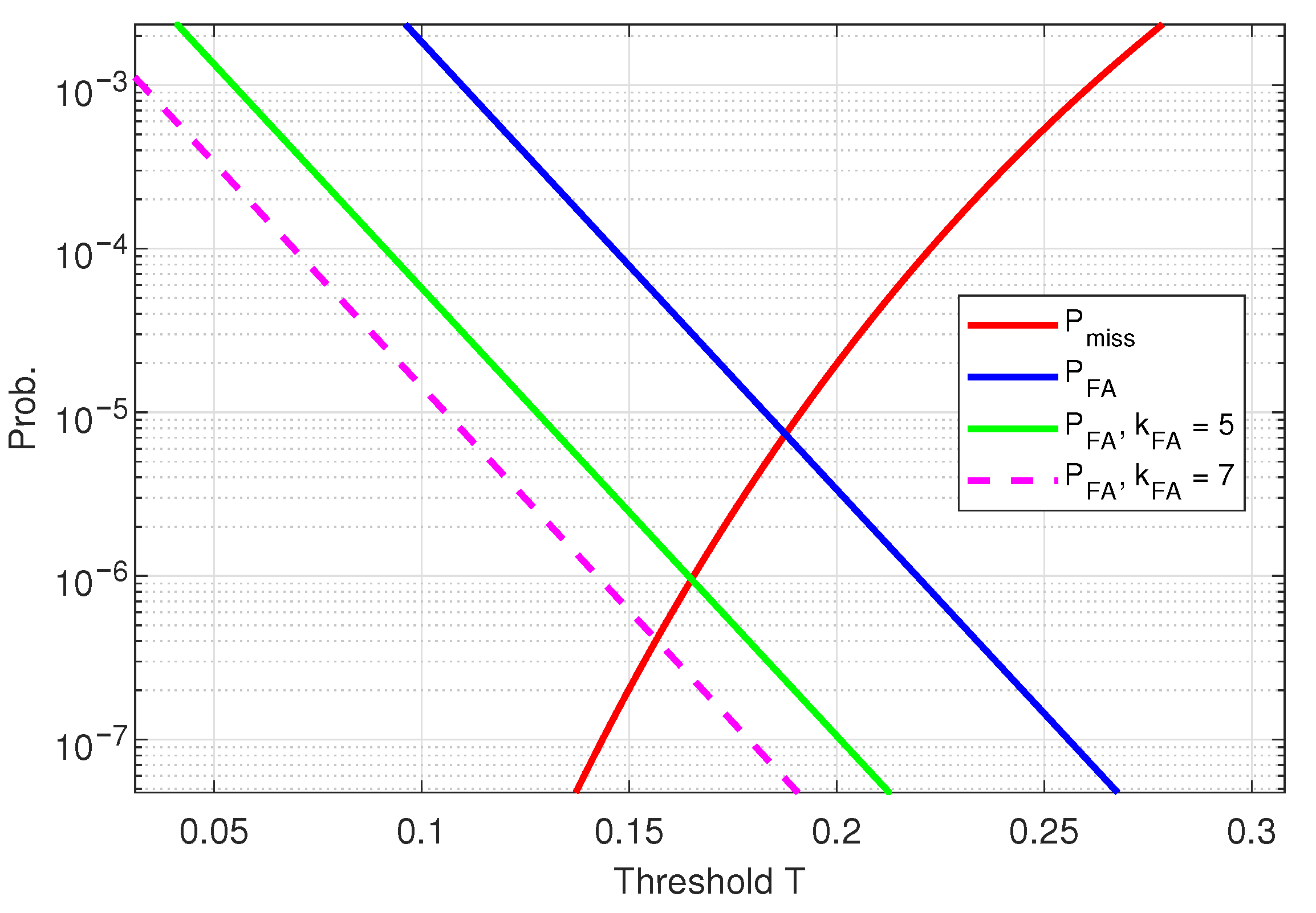
P F A , F A P ( T ) = P F A ( T ) 2 k F A .
Figure 13 shows how P F A will be reduced for different values of k F A , recalling P F A curve of Figure 10. Both curves for k F A = 5 (green) and k F A = 7 (magenta) are derived from Equation (28). Note that Equation (28) does not depend on the actual length of the FA field, which gives the system designer an additional degree of freedom to choose n F A accordingly.
In case of a false alarm event, the residual blocking time depends only on the duration of the FAP field n F A and the processing delay n d e c o d i n g to decode the received FAP code word. Table 4 summarizes the Rx blocking duration savings, when we assume that n F A + n d e c o d i n g = 100 T s y m , i.e., in case of a residual false alarm event, the Rx is blocked for 100 symbols only. Table 4 recalls the initial example given in Table 3.
A critical design constraint of the FAP sequence is that it provides a low frame error rate (FER) even at low SNR. Ideally, the FER of the FAP field shall be much lower than the FER of the regular payload FEC, which is used inside the radio frame. Hence, the generation of FAP sequences becomes crucial, as explained in the next sub-section.

4.2.3. FAP Code Generation

The easiest way to generate a FAP FEC with short frame length (e.g., n F A < 64 , k F A < 9 ) and arbitrary code rate is to use the maximum Hamming distance computer search (MHDCS) method. The variable k F A denotes the number of info bits, which are encoded. The MHDCS method iteratively generates 2 k F A random binary sequences (code words) of length n F A . This set of 2 k F A code words forms one code book B, which is an ordered set of code words with index q. Let the q-th code word out of B be denoted as vector B [ q ] . Subsequently, the Hamming distance among all code words is calculated on that code book B as the following:
D m i n = min q , p B [ q ] B [ p ] 2 q , p 0 , , 2 k F A 1 , p q .
Hence, the Hamming distance of B is the minimum Hamming distance of two code words out of B. During brute-force computer search, N I t code books are generated where B l denotes the l-th randomly generated Code Book. The code book B F E C is finally selected, which provides the maximum Hamming distance:
B F E C = max l = 1 : N I t D m i n ( B l ) .
As stated in [25], the Hamming distance directly affects the FER performance of a given block code. Hence, the target of the brute force MHDCS is to maximize D m i n . For sake of brevity, we assume that all code words B[p] of B F E C contain binary data symbols { 1 , 1 } . We are aware of the fact that FEC and Hamming distances are often defined on unipolar binary data (bits) { 0 , 1 } . In order to shorten the notation in this paper, we inherently assume that all code words exhibit bi-polar BPSK-type data symbols { 1 , 1 } , which can be mapped to or from unipolar bits.

4.2.4. FAP Coherent Demodulation and ML-Decoding

Coherent FAP field demodulation and decoding require a channel estimation, which yields the complex channel coefficient h ^ = h ^ e j ϕ h ^ . The channel coefficient h ^ is used to equalize the FAP symbols by
x ^ F A P [ k ] = y F A P [ k ] h ^ .
The following Figure 14 illustrates channel estimation and FAP equalization.
Let x ^ F A P be the equalized BPSK symbol vector of length n F A and B [ p ] be the p-th code word of code book B F E C . Then, the ML decoding can be performed as follows, assuming prior amplitude and phase equalization:
p M L = arg min p x ^ F A P B [ p ] 2 with p [ 0 , , 2 k F A 1 ] .
It is evident that coherent demodulation and FEC decoding are computationally complex. Hence, we need to introduce a modification of the coherent FAP demodulator and ML decoder, which avoid channel estimation and equalization. This alternative demodulator/decoder uses cross-correlation and is shown in the next sub-section.

4.2.5. FAP Cross-Correlation Reception and Decoding

Let y F A P [ k ] be the received FAP BPSK symbols, and B [ p ] be the p-th code word of code book B F E C . The received symbols are assumed to be neither amplitude nor phase equalized. The FEC decoding is carried out by cross-correlation as follows:
p M L = arg max p k = 0 n F A 1 y F A P [ k ] B * [ p , k ] 2
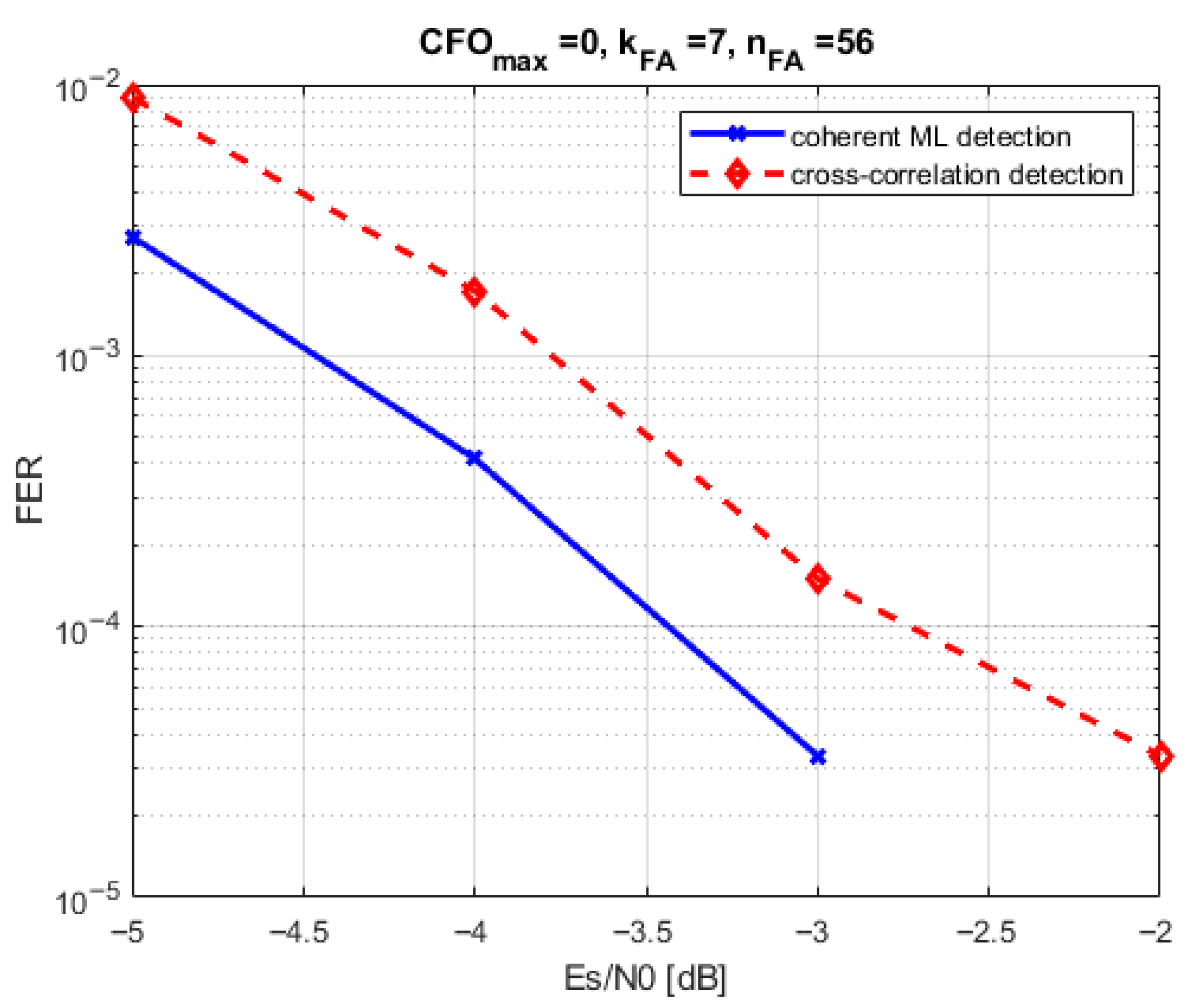
where B * [ p , k ] denotes the conjugate complex of the k-th element of code word B [ p ] . The cross-correlation demodulation technique avoids complex channel estimation and symbol equalization. The drawback is a slight performance loss compared to coherent ML decoding in plain AWGN environments with low residual CFO.

4.2.6. FAP Decoding Performance

In order to illustrate the FAP decoding performance, we are using Monte-Carlo FER simulations. A preamble of 127 BPSK symbols is used for channel estimation in case the coherent ML demodulator/decoder is used. The code rate r F A = 1/8 with k F A = 7 and n F A = 56 . The FAP sequence is BPSK encoded, and the MHDCS used N I t = 10 6 iterations for brute force code book search. Figure 15 shows FER vs. Es/N0 performance for the plain AWGN case, where no CFO is present. If the CFO becomes stronger, the coherent ML demodulator/decoder loses performance as shown in Figure 16. Here, the CFO was randomly selected from an interval [ Δ ν m a x : Δ ν m a x ] in each simulation run.
If the Doppler pre-compensation works properly, the residual maximum CFO, which is still present in the signal shall be in the order of Δ ν m a x 10 4 . However, we recommend using higher Δ ν m a x in performance simulation to account for fault situations and unknown receiver oscillator frequency offsets, which cannot be compensated by ground terminal Doppler pre-compensation. Hence, we choose Δ ν m a x = 10 2 (relative to symbol rate) in system simulations to account for the worst case situations. Such high CFO of Δ ν m a x = 10 2 leads to situations where the coherent ML decoder does not work at all, as illustrated in Figure 17. The cross-correlation approach shows substantial performance loss too.
However, the cross-correlation approach can be extended toward hypothetical CFO compensation as follows:
p M L = arg max p , l k = 0 n F A 1 y F A P [ k ] B * [ p , k ] e j 2 π ν l k 2 .
Figure 17 shows the effect of cross-correlation demodulation using 3 CFO hypotheses: 5 × 10 3 , 0 , 5 × 10 3 . The three CFO hypotheses are heuristically derived from the simulation results given in Figure 16 and Figure 17 since a CFO granularity of 5 × 10 3 still allows for reasonably low FER. Obviously, the FAP decoding can be used in low SNR even under strong residual CFO values thanks to the cross-correlation approach and a limited number of CFO hypotheses. However, there is a substantial drawback of the separate FAP field, which is inserted into the regular frame structure. The drawback is simply that yet existing radio signal standards do not foresee such a separate FAP field in the regular burst structure. Moreover, when designing new radio signal specs from scratch, one tries to avoid extra FAP overhead to maximize spectral efficiency. Hence, we propose using preamble sub-sequence FAP coding to realize FA prevention with existing known sequences. Such known sequences are the already described preamble sequences, as they are available in most of the currently used radio signal standards.

5. Preamble Sub-Sequence FAP Coding

Using a separate FA prevention field reduces spectral efficiency and is therefore not efficient with respect to short UL PHY signaling fields. We now show that preamble sub-sequence FAP coding allows for false alarm detection using given preamble sequences without adding any overhead to the uplink packet. Hence, the proposed preamble sub-sequence FAP coding allows for low receiver blocking without enlarging the preamble sequence length nor altering the preamble sequence. This is of major importance: the proposed sub-sequence FAP coding is explicitly compatible with existing LEO communication standards such as DVB-RCS2 and 3rd Generation Partnership Project New Radio Non-Terrestrial Networks (3GPP NR NTN).
The solution is to use a n F A length sub-sequence of either the preamble or some other form of already existing known signal structure. The idea is to perform the maximum Hamming distance computer search method on that given sub-sequence. The only difference to MHDCS as explained in Section 4.2.3 is that the existing preamble sub-sequence will be set as the first code word of the code book B F E C :
B [ p ] = preamble sub seq . p = 0 obtained by MHDCS p = 1 , , 2 k F A 1 .
In other words, the selected preamble sub-sequence is regarded as regular part of the code book (entry p = 0). The rest of the code book which provides maximum Hamming distance must be found by a computer search. A separate FAP field is no longer necessary (see Figure 18). By this method, any known preamble or pilot sequence can be used for the FA prevention while being regarded as regular part of a code book.
Figure 19 shows that there is no performance difference between the preamble sub-sequence FAP coding and a separate FAP field. The same simulation parameters are set as conducted in Section 4.2.6. As explained in Section 4.2.6, the robustness against phase and CFO distortions can be obtained using the cross-correlation approach with a limited number of CFO hypotheses.
It is evident that preamble sub-sequence FAP coding allows for false alarm detection using given preamble sequences without adding any overhead to the uplink packet. Hence, the proposed preamble sub-sequence FAP coding allows for low receiver blocking without enlarging the preamble sequence length, which would decrease the spectral efficiency of the uplink signal.

6. Conclusions

In this article, we derived the initial uplink synchronization procedure of an LEO SATCOM ground terminal, which exploits the properties of the LEO downlink carrier. We showed that simple blind estimation algorithms can be used to detect the presence of the downlink carrier and estimate its SNR. The results show that the blind Doppler estimation works even at low SNR (−4 dB), where the LEO downlink carrier is often even not decodable. We illustrate how to use a simple tracking loop to constantly correct Doppler shift and Doppler rate in the uplink signal transmitter. We, hence, believe that the simplicity of this initial procedure allows its usage in even small and low-cost terminals, which are not able to perform GNSS-based satellite tracking. The uplink burst reception is heavily impacted by packet detection false alarm events in the early phase of the LEO overflight. We show that the false alarm prevention is possible by using preamble sub-sequence coding and cross-correlation based decoding. Robustness against residual CFO, which originate from an imperfect coarse frequency offset compensation, can be achieved by using a limited set of CFO hypotheses. The proposed method of preamble sub-sequence coding and maximum Hamming distance code book search provides the possibility to achieve FAP without using a separate FAP sequence in the regular frame structure.

Funding

The work was funded under the research grant “FH-Kooperativ, FUBE”, grant number 13FH527KX0.

Data Availability Statement

The original contributions presented in this study are included in the article. Further inquiries can be directed to the corresponding author.

Conflicts of Interest

The author declares no conflicts of interest.

Abbreviations

The following abbreviations are used in this manuscript:
BBBase band
BPSKBinary phase shift keying
DFTDiscrete Fourier transformation
DLDown link
DVB-S2Digital video broadcast, satellite
CFOCarrier frequency offset
CRCcyclic redundancy check
FAFalse alarm
FAPFalse alarm prevention
FECForward error correction
FERFrame error rate
FFTFast Fourier transformation
GNSSGlobal navigation satellite system
ICARUSInternational cooperation for animal research using space
LEOLow earth orbit
LTELong-term evolution mobile communications
MF-TDMAMulti-frequency time division multiple access
MHDCSMaximum hamming distance code search
MLMaximum likelihood
MODCODModulation and coding scheme
OFDMAOrthogonal frequency division multiple access
PDFProbability density function
PHYPhysical layer
PNPseudo-noise
QPSKQuadrature phase shift keying
RACHRandom access channel
ROCReceiver operating characteristics
RRCRoot raised cosine
RVRandom variable
SNRSignal to noise ratio
ULUplink

References

  1. Humphreys, T.E.; Iannucci, P.A.; Komodromos, Z.M.; Graff, A.M. Signal Structure of the Starlink Ku-Band Downlink. IEEE Trans. Aerosp. Electron. Syst. 2023, 59, 6016–6030. [Google Scholar] [CrossRef]
  2. Krondorf, M.; Goblirsch, M.; Gaudenzi, R.; Cocco, G.; Toptsidis, N.; Acar, G. Towards the implementation of advanced random access schemes for satellite IoT. Int. J. Satell. Commun. Netw. 2020, 38, 177–199. [Google Scholar] [CrossRef]
  3. Krondorf, M.; Bittner, S.; Plettemeyer, D.; Knopp, A.; Wikelski, M. ICARUS—Very Low Power Satellite-Based IoT. Sensors 2022, 17, 6329. [Google Scholar] [CrossRef] [PubMed]
  4. Abramson, N. The ALOHA System—Another Alternative for Computer Communications. AFIDS Conf. Proc. 1970, 37, 281–285. [Google Scholar]
  5. Pan, M.; Hu, J.; Yuan, J.; Liu, J.; Su, Y. An Efficient Blind Doppler Shift Estimation and Compensation Method for LEO Satellite Communications. In Proceedings of the IEEE 20th International Conference on Communication Technology (ICCT), Nanning, China, 28–31 October 2020; pp. 643–648. [Google Scholar] [CrossRef]
  6. Liu, Y.; Su, Y.; Zhou, Y.; Cao, H.; Shi, J. Frequency Offset Estimation for High Dynamic LEO Satellite Communication Systems. In Proceedings of the 2019 11th International Conference on Wireless Communications and Signal Processing (WCSP), Xi’an, China, 23–25 October 2019; pp. 1–6. [Google Scholar] [CrossRef]
  7. Lin, X.; Lin, Z.; Lowenmark, S.E.; Rune, J.; Ericsson, R.K. Doppler Shift Estimation in 5G New Radio Non-Terrestrial Networks. In Proceedings of the 2021 IEEE Global Communications Conference (GLOBECOM), Madrid, Spain, 7–11 December 2021. [Google Scholar]
  8. Peters, E.G.W.; Day, K.; Benson, C.R. A real-time Doppler compensating physical/data link layer protocol for satellite communications. In Proceedings of the 2020 IEEE Aerospace Conference, Big Sky, MT, USA, 7–14 March 2020; pp. 1–11. [Google Scholar] [CrossRef]
  9. Cao, Y.; Zhang, T. Two stage frequency offset pre-compensation scheme for satellite mobile terminals. In Proceedings of the 2018 13th IEEE Conference on Industrial Electronics and Applications (ICIEA), Wuhan, China, 31 May–2 June 2018; pp. 117–122. [Google Scholar] [CrossRef]
  10. Sultan, Q.; Ha, S.; Choi, S.; Cho, Y.S. Downlink Synchronization in New Radio (NR) Non-Terrestrial Networks (NTN). In Proceedings of the 2022 13th International Conference on Information and Communication Technology Convergence (ICTC), Jeju Island, Republic of Korea, 19–21 October 2022; pp. 1351–1353. [Google Scholar] [CrossRef]
  11. Riedl, T.J.; Singer, A.C. Broadband Doppler compensation: Principles and new results. In Proceedings of the 2011 Conference Record of the Forty Fifth Asilomar Conference on Signals, Systems and Computers (ASILOMAR), Pacific Grove, CA, USA, 6–9 November 2011; pp. 944–946. [Google Scholar] [CrossRef]
  12. Zhou, Z.; Accettura, N.; Prévost, R.; Berthou, P. Lightweight synchronization to NBIoT enabled LEO Satellites through Doppler prediction. In Proceedings of the 2023 19th International Conference on Wireless and Mobile Computing, Networking and Communications (WiMob), Montreal, QC, Canada, 21–23 June 2023. [Google Scholar]
  13. EN 301 545-2 V1.3.1; DVB-RCS2 (Second Generation Return Channel Satellite)—Lower Layer. European Telecommunications Standards Institute (ETSI): Sophia Antipolis, France, 2020.
  14. Wünsche, R.; Krondorf, M. Memory Based Compensation of Phased Array Beamforming Antenna Gain Loss in LEO Satellite Systems Using Fourier Series. In Proceedings of the 64th International Symposium ELMAR-2022, Zadar, Croatia, 12–14 September 2022. [Google Scholar]
  15. 3GPP TR38.811; Study on New Radio (NR) to Support Non-terrestrial Networks, Release 16. 3GPP: Sophia Antipolis, France, 2018.
  16. Oerder, M.; Meyr, H. Digital filter and square timing recovery. IEEE Trans. Commun. 1988, 36, 605–612. [Google Scholar] [CrossRef]
  17. Morelli, M.; Mengali, U. Feedforward frequency estimation for PSK: A tutorial review. Eur. Trans. Telecommun. 1998, 9, 103–116. [Google Scholar] [CrossRef]
  18. IEEE. WiFi Standard Technical Documentation for IEEE 802.11n-2009. Available online: https://standards.ieee.org/ieee/802.11n/3952/ (accessed on 15 September 2025).
  19. LoRa-Alliance. LoRaWAN Technical Specification: TS001-1.0.4 LoRaWAN L2 1.0.4 Specification. Available online: https://lora-alliance.org/ (accessed on 15 September 2025).
  20. Heiskala, J.; Terry, J. Ofdm Wireless LANs: A Theoretical and Practical Guide; SAMS Publishing: Indianapolis, IN, USA, 2001. [Google Scholar]
  21. Martinez, A.B.; Kumar, A.; Chafii, M.; Fettweis, G. A New Approach for Accurate Time Synchronization Using Chirp Signals. In Proceedings of the IEEE Vehicular Technology Conference (VTC Spring 2020), Antwerp, Belgium, 25–28 May 2020. [Google Scholar] [CrossRef]
  22. Bizon Franco de Almeida, I.; Chafii, M.; Nimr, A.; Fettweis, G. Alternative Chirp Spread Spectrum Techniques for LPWANs. IEEE Trans. Green Commun. Netw. 2021, 5, 1846–1855. [Google Scholar] [CrossRef]
  23. Kelly, H.Z.; O’Malley, A.J.; Mauri, L. Receiver-Operating Characteristic Analysis for Evaluating Diagnostic Tests and Predictive Models. Circulation 2007, 115, 654–657. [Google Scholar] [CrossRef] [PubMed]
  24. European Telecommunications Standards Institute (ETSI). DVB-S2x Standard Document: ETSI EN 302 307-2 V1.1.1 (2014-10). 2014. Available online: https://www.etsi.org/ (accessed on 15 September 2025).
  25. Costello, L. Error Control Coding: Fundamentals and Applications; Pearson: London, UK, 2004; ISBN 013042672. [Google Scholar]
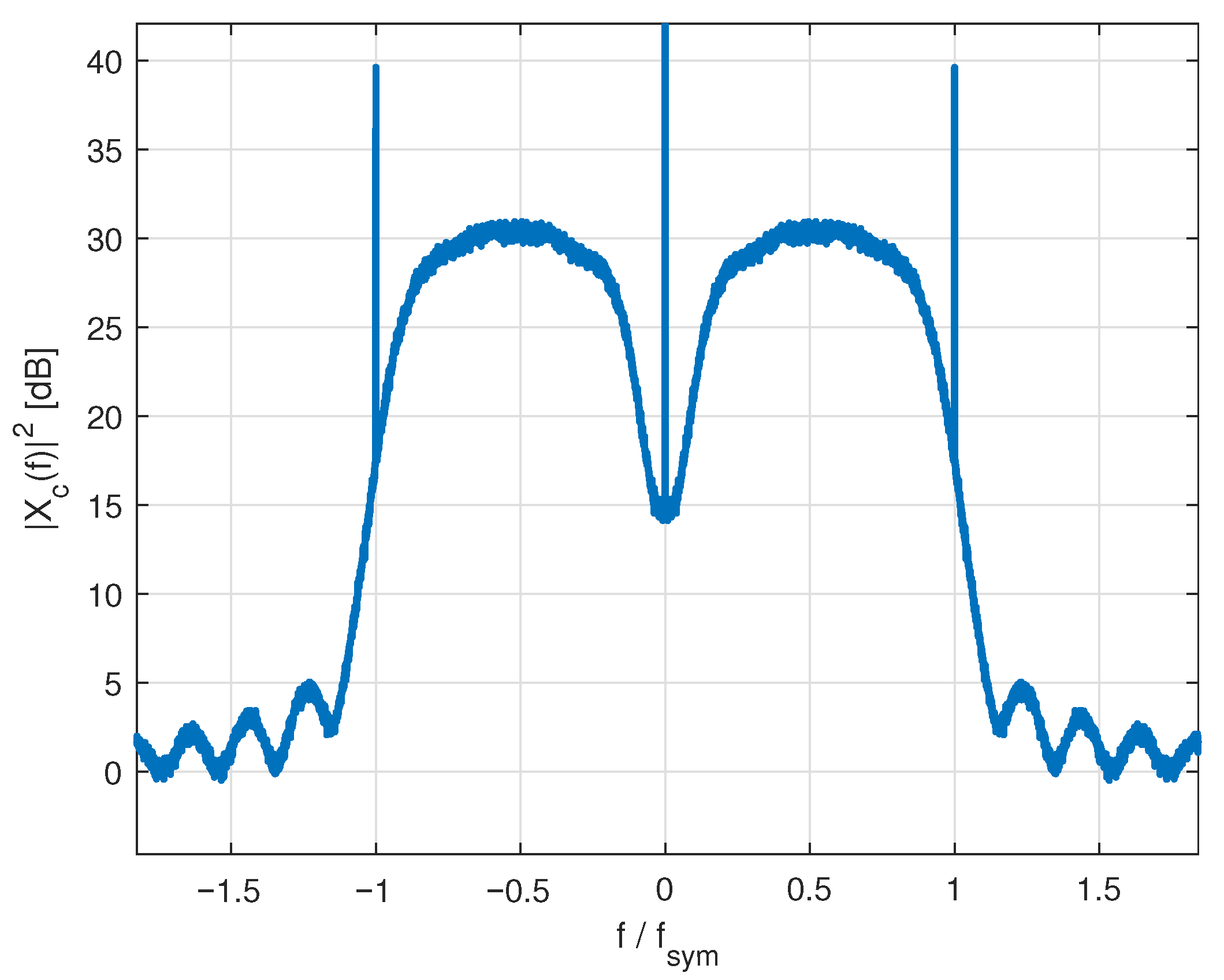
Figure 1. Spectrum X c ( f ) 2 , roll-Off 10%.
Telecom 06 00081 g001
Figure 2. Two-bin RSSI estimator schematic.
Telecom 06 00081 g002
Figure 3. RSSI metric vs. γ D L , averaged over 500 × 10 3 symbols.
Telecom 06 00081 g003
Figure 4. Principal schematic of the blind Doppler shift estimation.
Telecom 06 00081 g004
Figure 5. RMS Δ ν was normalized to baud rate vs. γ D L , FFT size 16k, averaged over 256 FFT frames.
Telecom 06 00081 g005
Figure 6. Doppler frequency tracking loop.
Telecom 06 00081 g006
Figure 7. Doppler shift tracking error vs. time.
Telecom 06 00081 g007
Figure 8. Doppler rate tracking vs. time.
Telecom 06 00081 g008
Figure 9. Cross-correlator used in packet detection.
Telecom 06 00081 g009
Figure 10. ROC example, BPSK PN-sequence, L = 63 , SNR = 0 dB, CFO ν = 0 .
Telecom 06 00081 g010
Figure 11. Typical LEO uplink signal structure at frame start.
Telecom 06 00081 g011
Figure 12. FAP field insertion after preamble.
Telecom 06 00081 g012
Figure 13. ROC example, BPSK PN-sequence, L = 63 , SNR = 0 dB, CFO ν = 0 .
Telecom 06 00081 g013
Figure 14. Coherent FAP field demodulation and ML decoding.
Telecom 06 00081 g014
Figure 15. FAP decoding performance, r F A = 1 / 8 , no CFO.
Telecom 06 00081 g015
Figure 16. FAP decoding performance, r F A = 1 / 8 , Δ ν m a x = 10 3 .
Telecom 06 00081 g016
Figure 17. FAP decoding performance, r F A = 1 / 8 , Δ ν m a x = 10 2 .
Telecom 06 00081 g017
Figure 18. Preamble sub-sequence FAP coding.
Telecom 06 00081 g018
Figure 19. Preamble sub-sequence FAP coding, r F A = 1 / 8 , Δ ν m a x = 10 2 .
Telecom 06 00081 g019
Table 1. Average and worst case Doppler parameters.
Orbit [km] f c [GHz]av. ν [kHz]wc ν [kHz]av. r d [Hz/s]
4000.456965
4000.851116123
4001.51929217
4003.54467505
4005.570105794
40010.01271911444
40012.01532291733
40020.02543812888
40027.03435153890
Table 2. Simulation parameters.
f s y m 40 MHz
N o s 5
FFT Size K16k
FFT Averaging512
Number of channel estimations ν ^ per second23
Δ ν m a x 6.1 kHz
r d at start−3.3 kHz/s
Doppler acceleration−80 Hz/ s 2
k p , k i 0.03, 0.01
Downlink SNR−4 dB
Table 3. False alarm events and Rx blocking.
SNRThresholdFA Events per SecondRx Blocking Time Duration
<3 dB0.171010%
3 dB–5 dB0.2033%
>5 dB0.250.20.2%
Table 4. False alarm events and Rx blocking with FAP.
SNRTFA Events per SecondRx Blocking TimeRx Blocking with FAP k FA = 6
<3 dB0.171010%0.15%
3 dB–5 dB0.2033%0.05%
>5 dB0.250.20.2%0.003%
Disclaimer/Publisher’s Note: The statements, opinions and data contained in all publications are solely those of the individual author(s) and contributor(s) and not of MDPI and/or the editor(s). MDPI and/or the editor(s) disclaim responsibility for any injury to people or property resulting from any ideas, methods, instructions or products referred to in the content.