Abstract
A compact fork-shaped four-element multiple-input multiple-output (MIMO) antenna system with wide bandwidth for 5G millimeter-wave (mmWave) applications is presented. The antenna elements are arranged orthogonally to achieve a compact footprint of . To enhance the gain, a frequency selective surface (FSS) is placed above the MIMO system, providing an average gain improvement of 1.5 dB across the entire operating band and achieving a peak gain of 7.5 dB at 41 GHz. The proposed design operates in the Ka-band (22–46 GHz), making it well suited for 5G communications. The antenna exhibits an isolation greater than 20 dB and radiation efficiency exceeding 80% across the band. Moreover, key MIMO performance metrics, including diversity gain (DG ≈ 10) and envelope correlation coefficient (ECC < 0.05), meet the required standards. A prototype of the proposed system was fabricated and measured, with the experimental results showing good agreement with simulations.
1. Introduction
Fifth generation (5G) wireless technology is expected to increase the data rate, while accommodating more connected devices, with reduced latency, energy consumption, cost, and spectrum utilization. The International Telecommunication Union (ITU) has divided the 5G communication spectrum into sub-6 GHz [1,2,3,4,5] and millimeter-wave (mmWave) frequency bands [6,7]. The mmWave frequency band offers numerous advantages, such as high resolution, fast data transfer, compact antenna dimensions, low interference (enhancing immunity to congestion), low cost, and high security [8,9]. Due to these benefits, mmWave antenna arrays have been extensively investigated and shown to meet the high throughput demands of users, while enabling compact designs with closely spaced antenna elements [10]. One approach involves integrating electromagnetic band gap (EBG) structures into the ground plane, although such designs can be complex. However, a major challenge at mmWave frequencies is the inevitable mutual coupling between antenna elements, which can degrade gain and efficiency [11]. Moreover, isolation can be improved by increasing inter-element spacing or by introducing decoupling structures and other isolation techniques. For instance, the authors in [12] proposed a miniaturized multiple-input multiple-output (MIMO) antenna based on metamaterials for 5.8 GHz WLAN applications, achieving up to 50 dB isolation using integrated metamaterial absorber unit cells [13,14,15]. Similarly, in [13], several EBG surfaces were employed to achieve an isolation enhancement of approximately 50 dB within a 5.8–6.4 GHz impedance bandwidth. By incorporating three double F-shaped etchings into the array ground plane, the isolation bandwidth was increased from 4.0 to 6.5 GHz (48%), with an isolation improvement from 10 dB to 40 dB across the operating band. These structures effectively suppress surface waves propagating through the substrate. Metallic vias have also been investigated as a simple decoupling technique for dielectric resonator antenna (DRA) arrays at mmWave frequencies. At 26 GHz, isolation was improved from 15.1 to 34.2 dB for an H-plane-connected MIMO DRA array and from 13.1 to 43 dB for an E-plane array [14]. The authors in [15] proposed a slot-array patch antenna with a defected ground structure (DGS) and achieved 50 dB isolation between 1.2 and 1.35 GHz for a circular polarized (CP) antenna with 0.057 inter-element spacing. To mitigate backward radiation from the slot-array DGS, a wheel-shaped absorber was introduced, achieving more than 95% absorptivity in the 1.2–1.35 GHz range and reducing backward radiation by over 12.5 dB () and 16.1 dB (). In [16], a dielectric block (DB) decoupling method was proposed for MIMO patch antennas, reducing the coupling between closely spaced elements in both the E and H planes by more than 20 dB over 4.32–5.48 GHz. The FSS has allocated the 28 GHz band (27.5–28.35 GHz) for 5G applications. In [17], a MIMO DRA with metal strips improved isolation by up to 12 dB in this band. Similarly, modifying the patch antenna layout in a slot operating at 56.5–64 GHz increased isolation by up to 38.6 dB [18]. A U-shaped coupling slot with microstrip feed, symmetrically placed along the x- and y-axes, provided balanced radiation performance for polarization diversity. This self-isolated 5G mmWave MIMO antenna (King Fahd University of Petroleum and Minerals, Dhahran, Saudi Arabia) achieved a maximum isolation improvement of 35 dB across 28–37.5 GHz, without requiring external decoupling structures [19].
In recent years, metasurface loading techniques have gained attention for improving antenna gain by manipulating the phase and amplitude of incident EM waves [20,21]. For instance, a dual-band metasurface operating at 7 and 17 GHz utilized C-shaped meta-particles to control the properties of the reflected and transmitted waves, achieving a gain improvement of 73% at 28 GHz. Similarly, a metasurface loading was used in [22] to reduce phase errors in Vivaldi apertures, resulting in a high-gain (12 dB) Vivaldi MIMO antenna (Central Research Facility, CARE, IIT Delhi, New Delhi, India) with pattern diversity for 5G mmWave applications. Other notable mmWave MIMO designs include a tree-shaped patch antenna covering 23–40 GHz with a peak gain of dB [23], and a 24.55–26.5 GHz MIMO antenna with a metasurface layer that achieved isolation of 25 dB and a gain of dB [24]. A dual-band MIMO antenna was presented in [25] that achieved >20 dB isolation in 23, 33, and 37.75–41 GHz bands. Finally, the authors of [26] presented a 4-port MIMO antenna operating in the 25–50 GHz band with orthogonal oriented elements and a truncated ground plane, achieving exceptional performance, having DG = 9.999 dB, ECC < 0.005, and mutual coupling < −10 dB. Recent studies have also explored compact mmWave antennas for body-centric and wearable applications, particularly in the n261 band (26–28 GHz) for 5G- and IoT-based health monitoring. For example, the authors of [27] presented a compact wideband antenna with a T-shaped radiator patch and ring-shaped ground plane, extended into an eight-element MIMO system. Although this design achieved isolation above 20 dB and low SAR for safe wearable use, it was limited to a narrow band and moderate gain (2–4 dB), while relying on complex slotting in the ground plane.
In this article, a high-performance four-element MIMO antenna is presented which is specifically tailored for 5G mmWave applications. The proposed antenna offers a wide impedance bandwidth and robust MIMO characteristics, essential for high-speed, high-capacity data transmission in next-generation 5G networks. The design incorporates a four-step configuration with a DGS, which plays a crucial role in achieving its wide band performance. An innovative arrangement transforms a single antenna into two perpendicular MIMO structures, which are subsequently expanded to four orthogonally positioned elements. This geometry effectively minimizes mutual coupling between the radiating elements. Furthermore, a frequency selective surface (FSS) is placed above the MIMO array at an optimized height H, leading to a notable enhancement in gain across the operating frequency band. This integrated design approach addresses critical challenges in 5G mmWave communication, delivering improved bandwidth, reduced interference, and enhanced overall system efficiency.
2. Optimization Strategies for a Single Antenna
The proposed antenna was developed through a systematic four-step optimization process, as illustrated in Figure 1. In the first step, we started with a T-shaped radiating patch and a half-ground plane that served as a baseline configuration. In the second step, the T-shaped patch was strategically modified into an L-shaped structure, while retaining the same ground plane. This modification marked a key stage in the iterative design process, enabling better performance. In the third step, the radiating patch was further transformed into a U-shaped configuration, now paired with a full ground plane, to enhance radiation characteristics and overall efficiency. Finally, in the fourth step, the U-shaped patch was maintained, but the bottom plane was deliberately modified to yield the final optimized design. This step-by-step evolution, guided by gradual geometry changes, reflected a purposeful and effective optimization approach to achieve the target antenna performance. The proposed antenna design demonstrated a clear performance progression in its four optimization steps, as illustrated in Figure 2a. In the first step, the reflection coefficient remained consistently below −10 dB within the 30–40 GHz range, indicating excellent impedance matching. In the second step, the performance improved further, achieving a wide impedance bandwidth from 27.2 to 42 GHz, with the reflection coefficient still below −10 dB. However, in the third step, the reflection coefficient rose above −10 dB, indicating a complete mismatch, likely due to the introduction of a full ground plane. This issue was resolved in the fourth step, which yielded the final proposed antenna configuration. In this optimized form, the antenna achieves an impressive wideband operation from 22 to 46 GHz, with consistently low reflection coefficients, making it highly suitable for 5G mmWave communication applications. The geometry of the proposed antenna is shown in Figure 3. The design features a U-shaped radiating patch with a partial bottom-ground plane. It is designed on a low-loss Rogers RT-Duroid 5880 (Rogers Corporation, Chandler, Arizona, USA) substrate with a thickness of 0.8 mm, a loss tangent of 0.0009, and a dielectric constant of 2.2. The general dimensions of the substrate are . A simple microstrip feed is employed to efficiently deliver maximum power to the radiator. The antenna was designed and simulated using CST Microwave Studio (CST MWS) Suite 2021, with radiation characteristics optimized through careful adjustment of key design parameters. Table 1 summarizes the final design values of the proposed antenna. The reflection coefficient of the proposed antenna is strongly influenced by the presence and dimensions of the defected ground plane, as illustrated in Figure 2b. Parametric analysis revealed that variations in ground plane length have a direct and measurable impact on the antenna impedance characteristics. As shown in Figure 2b, adjustment of the ground plane length leads to corresponding changes in the reflection coefficient. At an optimal length of 5 mm, the antenna achieved a wide impedance bandwidth of 22–46 GHz within the target frequency range. Deviations from this optimal length caused fluctuations in the reflection coefficient, which may reduce bandwidth and degrade overall performance. These findings highlight the critical role of ground-plane optimization in ensuring that the antenna meets the desired bandwidth requirements and maintains reliable performance throughout the intended operating spectrum.
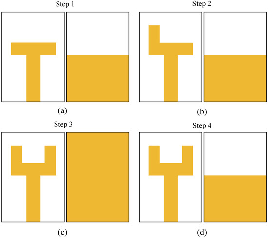
Figure 1.
Optimization (a) T-Shape with half ground (b) L-shape with half ground (c) U-shape with full ground and (d) U-shape with half ground are the steps of the proposed antenna design.

Figure 2.
Reflection coefficient responses of the proposed antenna: (a) optimization steps and (b) influence of the ground plane.
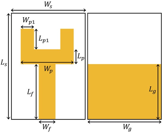
Figure 3.
Layout of the proposed antenna.

Table 1.
Design parameters of the fork-shaped antenna and MIMO system.
3. Two-Element Array System
Transformation of a single antenna into a two-element MIMO structure, as depicted in Figure 4, results in overall dimensions of . This transition to a MIMO configuration is aimed at enhancing overall system performance. The MIMO elements are positioned on the top side of the substrate, precisely arranged in a perpendicular orientation to each other. This arrangement optimizes spatial diversity, a critical characteristic of MIMO systems, enabling the antenna to exploit multipath propagation and mitigate the adverse effects of fading and signal interference. The compact dimensions of reflect careful consideration of size constraints, ensuring that the MIMO structure remains compact, while providing improved communication capabilities. The perpendicular alignment of the MIMO elements contributes to increased channel capacity, higher data rates, and enhanced system reliability, demonstrating a thoughtful integration of MIMO design principles for superior wireless communication performance. The MIMO S-parameters illustrated in Figure 5a proved to be highly promising, with a wide bandwidth (22–46 GHz) and impressive isolation (>20 dB) among radiation elements. This configuration ensures efficient signal management, making it ideal for diverse applications that require reliable communication across a broad frequency spectrum.

Figure 4.
Front and back view of two elements of the MIMO system.
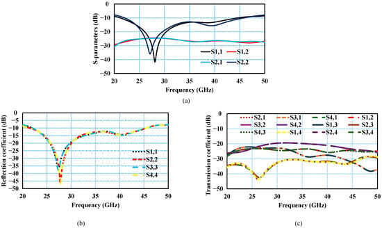
Figure 5.
S-parameters of proposed MIMO configurations: (a) two-element MIMO system, (b) four-element MIMO reflection coefficient, (c) four-element MIMO transmission coefficient.
4. Four-Element MIMO Configuration
The proposed antenna system represents a significant advancement in the realm of 5G mmWave communication, specifically designed to improve channel capacity and support high data traffic for reliable performance. In Figure 6a, the geometry of the MIMO system is presented, which highlights its four-port configuration. The deliberate orthogonal arrangement of MIMO elements on the substrate, perpendicular to each other, is a key feature aimed at achieving greater isolation, exceeding 20 dB, all without the need for a decoupling structure. This spatial arrangement ensures that the individual elements work cohesively, while minimizing interference. Furthermore, the back view illustrated in Figure 6b reveals an independent partial ground plane for each radiating element, arranged orthogonally. This design contributes to the overall isolation and effectiveness of the system. The compact dimensions of the MIMO configuration, measuring 20.8 mm3, underscore the suitability of the antenna for integration into compact 5G devices, focusing on efficiency and without compromising performance. The proposed MIMO system S-parameters, depicted in Figure 5a,b, exhibit significant potential, due to their wide impedance bandwidth, ranging from 22 to 46 GHz. Furthermore, these parameters demonstrate good isolation, exceeding 20 dB, between radiation elements. This characteristic is crucial for minimizing interference and improving signal integrity in high-frequency communication systems. The wide bandwidth and good isolation underscore the effectiveness of MIMO technology in facilitating robust and reliable wireless communication across a wide range of frequencies, promising enhanced performance and efficiency in various applications.
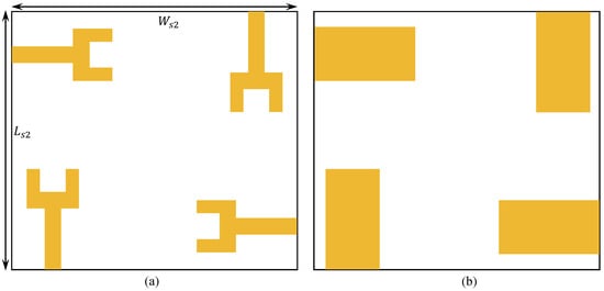
Figure 6.
(a) Front view and (b) back view of the proposed four-element MIMO system.
5. Unit Cell Optimization
The FSS unit cell presented in this paper is designed for mmWave applications operating in the range of 24–44 GHz. The proposed unit cell is implemented on a Rogers RT-Duroid 5880 (Rogers Corporation, Chandler, Arizona, USA) substrate with a thickness of 0.8 mm. The optimized unit cell consists of two rectangular split-ring resonators integrated into a combined H-shaped layout in the center, as illustrated in Figure 7b. Figure 7a depicts the stepwise development process of the unit cell. The reflection coefficient plot in Figure 7c confirms that the unit cell operates within the 24–44 GHz mmWave spectrum. Furthermore, the transmission coefficient curve shows that the unit cell exhibits nearly zero loss within the operating band, indicating full transmission throughout the desired frequency range.
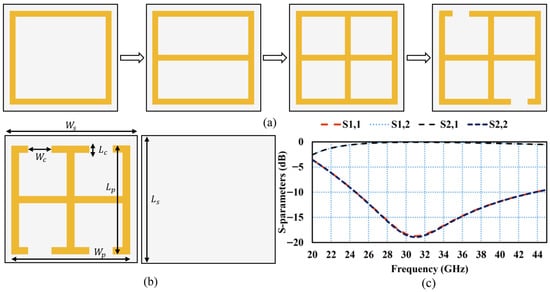
Figure 7.
(a) Unit cell steps, (b) unit cell geometry, (c) S-parameters of unit cell.
Subsequently, an FSS is achieved by periodic replication of unit cells with a small gap g, as shown in Figure 8a. The total size of the FSS is . The FSS structure exhibits a bandpass behavior and is positioned above the MIMO configuration, as illustrated in Figure 8b, at a height H that enhances the performance of the MIMO system. Following the integration of the FSS, the MIMO system demonstrated improved performance, as depicted in Figure 8c. The reflection coefficient curves of the MIMO system, before and after the addition of the FSS, show the same impedance bandwidth of 22–46 GHz. However, the transmission coefficient improved from 19 dB to 21 dB, indicating a slight improvement in isolation throughout the wide bandwidth, as shown in Figure 8c. To calculate the optimal height between the MIMO system and the FSS, the following equation is used [28]:
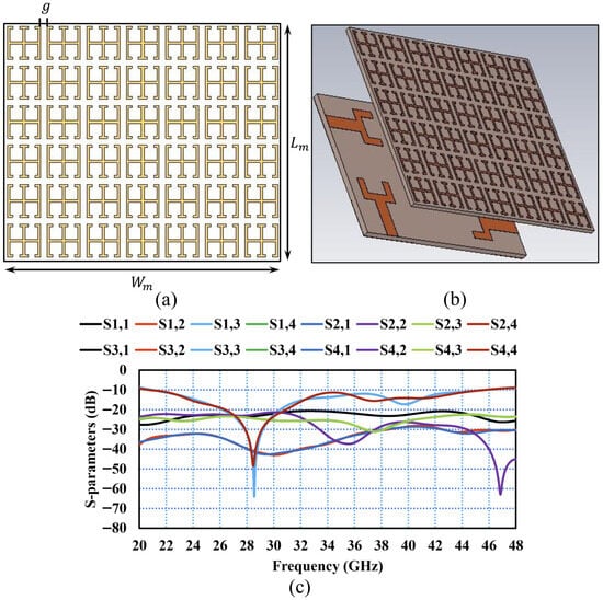
Figure 8.
(a) array FSS, (b) FSS-based MIMO system, (c) S-parameters of FSS-based MIMO.
FSS to Antenna Separation Justification
The separation H was chosen to satisfy the constructive interference condition:
where is the reflection phase of the FSS and . Hence,
At frequency f = 34 GHz, the free-space wavelength is , giving , and . For :
The round-trip phase is
and
Thus, the chosen height H = 7.5 mm satisfies the phase condition near 34 GHz, ensuring constructive reinforcement and yielding a measured gain of 7.5 dB at 41 GHz, with broadband performance across 22–46 GHz. Here, H is the height between the MIMO system and the FSS layer, is the phase of the reflected wave from the FSS, and is the propagation constant of the free space. The height between the MIMO system and the FSS layer must be an integer multiple of the wavelength corresponding to the central operating frequency. However, due to the wide bandwidth of the FSS layer, H was adjusted to achieve the maximum gain. A parametric study was conducted for the height between the MIMO system and the proposed FSS layer with a unit cell array. For mm, the MIMO system achieved a peak gain of 6.7 dB, as shown in Figure 9. Increasing the height to 7.5 mm improved the peak gain to 7.5 dB, while a further increase to 10 mm reduced the gain to 7.0 dB. Therefore, the optimal performance was achieved at mm, where the MIMO system with a FSS layer demonstrated the maximum gain.
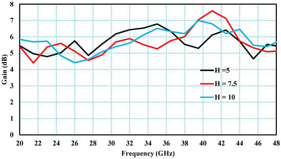
Figure 9.
Simulated gain with different height values between FSS and MIMO system.
Simulated patterns were calculated at several additional frequencies, as depicted in Figure 10, including 24 and 45 GHz, alongside the results measured at 28 and 37 GHz. The findings indicate that both the E-plane and H-plane responses remained stable across the band.
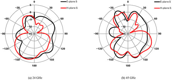
Figure 10.
Simulated E-plane and H-plane at (a) 24 and (b) 45 GHz for FSS-based MIMO system.
6. Experimental Analysis of Proposed MIMO Antenna
The presented MIMO system with an FSS surface was fabricated, as shown in Figure 11, for experimental verification. To employ the FSS above the MIMO system, a specific foam was used as a spacer. During the measurement process, the antenna was connected using high-quality 2.4 mm connectors and low-loss coaxial cables to minimize signal degradation. A TRL (Thru-Reflect-Line) calibration was performed on the vector network analyzer to eliminate systematic errors and improve accuracy. To further enhance reliability, cable and connector losses were accounted for through calibration and de-embedding procedures, as depicted in Figure 11. A relative comparison of the simulated and measured results is discussed in the following sections. The S-parameters from both simulation and measurement are compared in Figure 12. The simulated and measured reflection coefficients of antenna 1 and antenna 4, operating in the 22–46 GHz range with an impedance bandwidth of 24 GHz, are shown in Figure 12a. Similarly, the transmission coefficients of antenna 1 and antenna 4 were analyzed with respect to antenna 2 and antenna 3. It was observed that a minimum isolation of 20 dB and a maximum isolation of 39 dB were achieved within the operating band, as depicted in Figure 12b. Minor discrepancies between the simulated and measured results were attributed to fabrication tolerances, calibration errors, and cable losses during measurement. In the proposed MIMO system, the radiation patterns were measured in an anechoic chamber, ensuring a controlled environment free from external reflections. Figure 13a,b present the measured and simulated radiation patterns for both the H-plane and the E-plane at two distinct frequencies, specifically 28 GHz and 37 GHz. For the H-plane, a main lobe was observed within the angular range of 90° to 150° for both frequencies. This indicates that most of the radiated energy in the H-plane is concentrated within this angular sector, reflecting the focused and directive nature of the antenna array. In contrast, the E-plane exhibited maximum radiation within the angular range of −150° to 150° at both frequencies, signifying a broader energy distribution in the vertical direction. This wider coverage in the E plane can be advantageous in scenarios where a larger elevation angle is required. Although radiation patterns at 28 and 37 GHz are illustrated to demonstrate the antenna’s capability for 5G applications, the analysis was also extended to cover the full operating band of 22–46 GHz. In general, the measured and simulated radiation patterns provide valuable insights into the directional characteristics of the proposed MIMO system, which are crucial for optimizing performance in various communication scenarios, particularly at 28 GHz and 37 GHz. Minor discrepancies between the measured and simulated results are attributed to fabrication tolerances and cable losses during measurement. It was observed that increasing the operating frequency resulted in more directive radiation patterns and improved gain of the radiating patch. A maximum gain of 7.5 dB was achieved at 41 GHz, as shown in Figure 14a [29]. Furthermore, with increasing gain, the efficiency of the radiating element also improved, achieving a maximum total efficiency of 93% at 30 GHz and maintaining more than 80% efficiency throughout the operating bandwidth, as depicted in Figure 14b. From the plots, it is evident that the measured results are in close agreement with the simulated results, as illustrated in Figure 14a,b. The measured −10 dB impedance bandwidth (22–46 GHz) shows a variation of about 4.5% compared to the simulations, which can be attributed to fabrication tolerances in substrate thickness ±0.05 mm and etching accuracy ±0.1 mm. Similarly, the measured isolation between antenna elements remained better than 20 dB across the band, with only 1–1.5 dB difference from simulated values, mainly due to connector and cable losses not fully captured in the simulations. In terms of efficiency, the measured peak value was 2–3% lower than simulated results, which is reasonable given the conductor losses, connector transitions, and alignment uncertainties in the measurement setup.
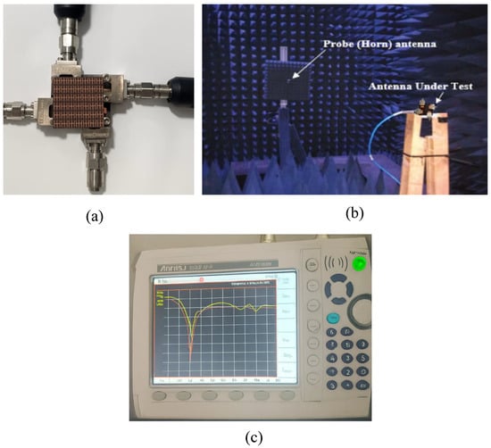
Figure 11.
Measurement setup and results: (a) TRL calibration of the vector network analyzer, (b) measurement setup inside the anechoic chamber, and (c) measured reflection coefficient (S11).

Figure 12.
FSS-based MIMO system: (a) simulated and measured reflection coefficients of Ant 1 and Ant 4, (b) simulated and measured transmission coefficients of Ant 1 and Ant 4.
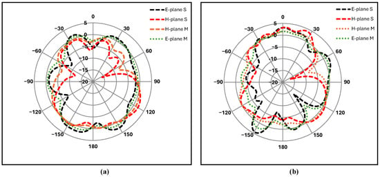
Figure 13.
Simulated and measured E and H planes of FSS-based MIMO system: (a) 28 GHz, (b) 37 GHz.
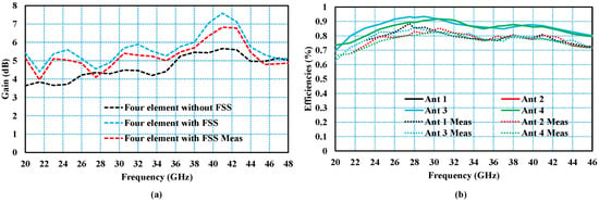
Figure 14.
Simulated and measured (a) gain, (b) total efficiency of FSS-based MIMO system.
The surface current distribution at 28 GHz across the four-element MIMO system based on FSS is shown in Figure 15. One port was excited and the other was terminated with a matched load. When Ant 1 was excited, this had little effect on Ant 3 and Ant 4 due to the orthogonal arrangement of the radiating elements, as shown in Figure 15a. The same behavior was observed for the other radiating elements, as shown in Figure 15. In addition, the FSS was stacked above MIMO elements; the current from the radiating elements was also distributed over the unit cells of the FSS surface, due to which coupling among the radiating elements was reduced. It is also important that the proposed design is applied in practical 5G use cases. The wide operating range (22–46 GHz) and stable radiation patterns make the antenna well suited for beamforming, where combining multiple elements can improve gain and directionality. This is a key requirement for mmWave 5G systems, which require focused beams to mitigate high path losses. The compact and planar structure of the antenna also makes it easier to integrate into mobile devices, although challenges such as mutual coupling between nearby elements and user-hand effects remain areas for future investigation. At the system level, the achieved gain and efficiency strengthen the link budget, ensuring reliable communication at the important 28 and 37 GHz bands, as well as across the full wideband. In general, these features confirm the practical value and potential use of the proposed antenna in wideband and multi-band 5G applications.
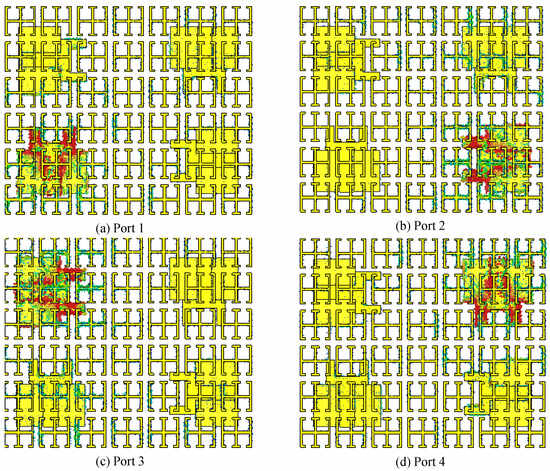
Figure 15.
Surface current distribution across each port (a) Port 1 (b) Port 2 (c) Port 3 and (d) Port 4 at 28 GHz of FSS-based MIMO system.
7. MIMO Performance Parameters
Some of the key performance parameters used to evaluate the MIMO antenna performance are discussed in the following section.
7.1. Envelope Correlation Coefficient
The envelope correlation coefficient (ECC) is a widely used MIMO performance metric, providing information on the correlation between the radiating elements in a MIMO system. A low correlation level is typically observed for independent antenna elements. The proposed MIMO structure exhibited a low ECC value (<0.005), which is well below the standard threshold of <0.5. For wideband antennas, the ECC is estimated from the radiation patterns [30,31] as
where and denote the radiation patterns when ports i and j are excited, respectively, and represents the solid angle. The proposed four-element FSS-based MIMO structure demonstrated a very low ECC, as shown in Figure 16, indicating excellent isolation among the radiating elements.
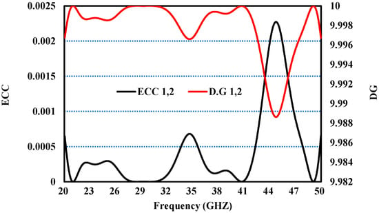
Figure 16.
ECC and DG of the FSS-based MIMO system.
7.2. Diversity Gain
The diversity gain (DG) of MIMO antennas represents the loss in transmission power for the MIMO configuration. It can be calculated as [32]
Figure 16 illustrates the DG curves of the proposed MIMO antenna, showing that the DG remained approximately 10 dB over the entire operating band, thus ensuring excellent diversity performance. The proposed MIMO configuration features a compact size, a wide bandwidth of 22–46 GHz, and remarkable isolation, greater than 20 dB, along with an efficiency of up to 93%, representing notable progress over previous studies. These attributes highlight its improved efficacy and practicality in high-frequency communication systems. The compact form factor enables easy integration into space-constrained environments, while the wide bandwidth ensures adaptability across multiple frequency bands. Furthermore, the high level of isolation effectively minimizes interference, ensuring reliable signal transmission. Achieving 93% efficiency demonstrates significant advancements in resource utilization, indicating superior performance and versatility for various applications. Although the earlier studies discussed in Table 2 and Table 3 presented MIMO antennas with and without metasurfaces or FSS layers, our work offers several new features that make it different. First, we designed a compact fork-shaped antenna using a step-by-step process and then arranged four elements in an orthogonal orientation. This design achieves more than 20 dB isolation, without using extra decoupling structures, which makes the antenna simpler and smaller than many existing designs. Second, instead of only using metasurfaces or defected ground structures for isolation, we carefully placed a frequency selective surface (FSS) at an optimized height (7.5 mm). This improves the antenna gain by about 1.5 dB across the band and gives a maximum gain of 7.5 dB. Third, the proposed antenna works over a very wide frequency range of 22–46 GHz, which is broader than many reported designs, and it also maintains a high efficiency of up to 93%. Finally, the design was not only tested in simulations, but also fabricated and measured, and the results closely match the simulations. Together, these points compact geometry, simple structure with good isolation, optimized FSS for gain improvement, wide bandwidth with high efficiency, and experimental verification show that our antenna makes a clear improvement over earlier MIMO + FSS or metasurface-based antennas.

Table 2.
Performance comparison of MIMO antennas with and without FSS enhancement.

Table 3.
Performance comparison of reported antennas with the proposed work.
8. Conclusions
This paper presents a four-element FSS-based MIMO antenna system designed for 5G mmWave communication within a wide frequency range of 22–46 GHz. The MIMO elements are arranged in an orthogonal orientation on a substrate measuring , achieving an impressive isolation of greater than 20 dB across the entire frequency spectrum. The MIMO architecture evolved from a single-element to a four-element configuration, a progression aimed at enhancing channel capacity and increasing data rates. In particular, the incorporation of an FSS stacked above the MIMO system results in a significant gain improvement, achieving a maximum of 7.5 dB and an outstanding total efficiency of 93%. Analysis of MIMO performance parameters, including the ECC and DG, further underscored the effectiveness of the proposed system. In addition, the proposed antenna was optimized on a Rogers RT-Duroid 5880, due to its low dielectric loss, stable performance, and availability in research labs. For practical 5G applications, thinner or low-cost substrates (e.g., FR4, flexible polymers) and multilayer PCB integration are often required, which may introduce higher losses, fabrication tolerances, and resonance shifts at mmWave frequencies. Integration with RF front-ends and packaging also requires careful co-design to minimize parasitics and interconnect issues. Future work will focus on low-cost substrate adaptations, multilayer stack-ups, and tolerance-aware design to maintain wideband operation and high efficiency, while also exploring reconfigurability, tunability, real-world testing, and integration with beamforming systems, to enhance scalability and practical deployment in compact 5G and IoT platforms.
Author Contributions
Conceptualization, I.U.D., D.K., A.U., M.A.O. and B.R.; Methodology, I.U.D., D.K., A.U. and M.A.O.; Software, I.U.D., D.K. and A.U.; Validation, I.U.D., D.K., A.U., M.A.O. and B.R.; Formal analysis, I.U.D., D.K., A.U., M.A.O. and B.R.; Investigation, I.U.D., D.K., A.U., M.A.O. and B.R.; Resources, I.U.D., M.A.O. and B.R.; Data curation, I.U.D., D.K., A.U., M.A.O. and B.R.; Writing original draft preparation, I.U.D., D.K. and A.U.; Writing review and editing, I.U.D., D.K., A.U., M.A.O. and B.R.; Visualization, I.U.D., D.K., A.U. and M.A.O.; Supervision, M.A.O. and B.R.; Project administration, M.A.O. and B.R.; Funding acquisition, M.A.O. and B.R. All authors have read and agreed to the published version of the manuscript.
Funding
This work is supported in part by MITACS acceleration program IT40639 with BCi Tech collaboration.
Data Availability Statement
The original contributions presented in this study are included in the article. Further inquiries can be directed to the corresponding author.
Acknowledgments
This work was supported in part by the MITACS acceleration program IT40639 on ‘AI-aided joint RF circuit and antenna design for holographic MIMO and reconfigurable intelligent surfaces’ in collaboration with BCi Tech Canada.
Conflicts of Interest
There are no competing interests to report.
References
- Rafique, U.; Khan, S.; Ahmed, M.M.; Kiani, S.H.; Abbas, S.M.; Saeed, S.I.; Alibakhshikenari, M.; Dalarsson, M. Uni-planar MIMO antenna for sub-6 GHz 5G mobile phone applications. Appl. Sci. 2022, 12, 3746. [Google Scholar] [CrossRef]
- Cheng, X.; Hu, Y.; Varga, L. 5G network deployment and the associated energy consumption in the UK: A complex systems’ exploration. Technol. Forecast. Soc. Chang. 2022, 180, 121672. [Google Scholar] [CrossRef]
- Kamal, M.A.; Raza, H.W.; Alam, M.M.; Su’ud, M.M.; Sajak, A.b.A.B. Resource allocation schemes for 5G network: A systematic review. Sensors 2021, 21, 6588. [Google Scholar] [CrossRef] [PubMed]
- Jain, A.K.; Acharya, R.; Jakhar, S.; Mishra, T. Fifth generation (5G) wireless technology “Revolution in telecommunication”. In Proceedings of the 2018 Second International Conference on Inventive Communication and Computational Technologies (ICICCT), Coimbatore, India, 20–21 April 2018; IEEE: New York, NY, USA, 2018; pp. 1867–1872. [Google Scholar]
- Sufyan, A.; Shah, S.A.A.; Khan, K.B.; Shah, I.A.; Ullah, A.; Siddiquu, T.A.; Yoo, H. Self-Decoupled 8-Element Dual Polarized MIMO Antenna for B5G Handsets With Sub-6 GHz and mmWave Integration. IEEE Access 2024, 12, 167324–167332. [Google Scholar] [CrossRef]
- Kiani, S.H.; Alharbi, A.G.; Khan, S.; Marey, M.; Mostafa, H.; Khan, M.A. Wideband three loop element antenna array for future 5G mmWave devices. IEEE Access 2022, 10, 22472–22479. [Google Scholar] [CrossRef]
- Luo, Y.; Shen, Y.; Cai, X.; Qian, F.; Xu, S.; Cui, H.; Yang, G. Substrate integrated coaxial line design for mmWave antenna with multilayer configuration. Int. J. RF Microw. Comput.-Aided Eng. 2022, 32, e23090. [Google Scholar] [CrossRef]
- Hong, W. Solving the 5G mobile antenna puzzle: Assessing future directions for the 5G mobile antenna paradigm shift. IEEE Microw. Mag. 2017, 18, 86–102. [Google Scholar] [CrossRef]
- Desai, A.; Upadhyaya, T.; Patel, R. Compact wideband transparent antenna for 5G communication systems. Microw. Opt. Technol. Lett. 2019, 61, 781–786. [Google Scholar] [CrossRef]
- Shen, X.; Liu, Y.; Zhao, L.; Huang, G.L.; Shi, X.; Huang, Q. A miniaturized microstrip antenna array at 5G millimeter-wave band. IEEE Antennas Wirel. Propag. Lett. 2019, 18, 1671–1675. [Google Scholar] [CrossRef]
- Jilani, S.F.; Alomainy, A. Millimetre-wave T-shaped MIMO antenna with defected ground structures for 5G cellular networks. IET Microw. Antennas Propag. 2018, 12, 672–677. [Google Scholar] [CrossRef]
- Madni, A.; Bilal, R.M.H.; Khan, W.T. A compact metamaterial based high isolation MIMO antenna for 5.8 GHz WLAN applications. In Proceedings of the 2022 IEEE International Symposium on Antennas and Propagation and USNC-URSI Radio Science Meeting (AP-S/URSI), Denver, CO, USA, 10–15 July 2022; IEEE: New York, NY, USA, 2022; pp. 245–246. [Google Scholar]
- Sokunbi, O.; Attia, H. Highly reduced mutual coupling between wideband patch antenna array using multiresonance EBG structure and defective ground surface. Microw. Opt. Technol. Lett. 2020, 62, 1628–1637. [Google Scholar] [CrossRef]
- Sikandar; Sharma, A.; Rai, J.K.; Katiyar, H. Design of a High Gain MIMO Dielectric Resonator Antenna for 5G mm-Wave Applications. In Proceedings of the 2023 International Conference on IoT, Communication and Automation Technology (ICICAT), Gorakhpur, India, 23–24 June 2023; IEEE: New York, NY, USA, 2023; pp. 1–5. [Google Scholar]
- Pan, Y.M.; Qin, X.; Sun, Y.X.; Zheng, S.Y. A simple decoupling method for 5G millimeter-wave MIMO dielectric resonator antennas. IEEE Trans. Antennas Propag. 2019, 67, 2224–2234. [Google Scholar] [CrossRef]
- Gao, D.; Cao, Z.X.; Fu, S.D.; Quan, X.; Chen, P. A novel slot-array defected ground structure for decoupling microstrip antenna array. IEEE Trans. Antennas Propag. 2020, 68, 7027–7038. [Google Scholar] [CrossRef]
- Zhang, Y.; Deng, J.Y.; Li, M.J.; Sun, D.; Guo, L.X. A MIMO dielectric resonator antenna with improved isolation for 5G mm-wave applications. IEEE Antennas Wirel. Propag. Lett. 2019, 18, 747–751. [Google Scholar] [CrossRef]
- Jang, T.H.; Kim, H.Y.; Kang, D.M.; Kim, S.H.; Park, C.S. 60 GHz low-profile, wideband dual-polarized U-slot coupled patch antenna with high isolation. IEEE Trans. Antennas Propag. 2019, 67, 4453–4462. [Google Scholar] [CrossRef]
- Sokunbi, O.; Attia, H.; Hamza, A.; Shamim, A.; Yu, Y.; Kishk, A.A. New self-isolated wideband MIMO antenna system for 5G mm-wave applications using slot characteristics. IEEE Open J. Antennas Propag. 2023, 4, 81–90. [Google Scholar] [CrossRef]
- Tian, H.W.; Zhang, X.G.; Jiang, W.X.; Li, X.; Liu, Y.K.; Qiu, C.W.; Cui, T.J. Programmable controlling of multiple spatial harmonics via a nonlinearly phased grating metasurface. Adv. Funct. Mater. 2022, 32, 2203120. [Google Scholar] [CrossRef]
- Bao, L.; Fu, X.; Wu, R.Y.; Ma, Q.; Cui, T.J. Full-space manipulations of electromagnetic wavefronts at two frequencies by encoding both amplitude and phase of metasurface. Adv. Mater. Technol. 2021, 6, 2001032. [Google Scholar] [CrossRef]
- Singh, M.; Parihar, M.S. Gain improvement of Vivaldi MIMO antenna with pattern diversity using bi-axial anisotropic metasurface for millimeter-wave band application. IEEE Antennas Wirel. Propag. Lett. 2022, 22, 621–625. [Google Scholar] [CrossRef]
- Sehrai, D.A.; Abdullah, M.; Altaf, A.; Kiani, S.H.; Muhammad, F.; Tufail, M.; Irfan, M.; Glowacz, A.; Rahman, S. A novel high gain wideband MIMO antenna for 5G millimeter wave applications. Electronics 2020, 9, 1031. [Google Scholar] [CrossRef]
- Tariq, S.; Naqvi, S.I.; Hussain, N.; Amin, Y. A metasurface-based MIMO antenna for 5G millimeter-wave applications. IEEE Access 2021, 9, 51805–51817. [Google Scholar] [CrossRef]
- Munir, M.E.; Kiani, S.H.; Savci, H.S.; Marey, M.; Khan, J.; Mostafa, H.; Parchin, N.O. A four element mm-wave MIMO antenna system with wide-band and high isolation characteristics for 5G applications. Micromachines 2023, 14, 776. [Google Scholar] [CrossRef] [PubMed]
- Abbas, M.A.; Allam, A.; Gaafar, A.; Elhennawy, H.M.; Sree, M.F.A. Compact UWB MIMO antenna for 5G millimeter-wave applications. Sensors 2023, 23, 2702. [Google Scholar] [CrossRef]
- Gupta, A.; Kumari, M.; Sharma, M.; Alsharif, M.H.; Uthansakul, P.; Uthansakul, M.; Bansal, S. 8-port MIMO antenna at 27 GHz for n261 band and exploring for body centric communication. PLoS ONE 2024, 19, e0305524. [Google Scholar] [CrossRef]
- Al-Gburi, A.J.A.; Ibrahim, I.B.M.; Zeain, M.Y.; Zakaria, Z. Compact size and high gain of CPW-fed UWB strawberry artistic shaped printed monopole antennas using FSS single layer reflector. IEEE Access 2020, 8, 92697–92707. [Google Scholar] [CrossRef]
- Din, I.U.; Ullah, W.; Abbasi, N.A.; Ullah, S.; Shihzad, W.; Khan, B.; Jayakody, D.N.K. A novel compact ultra-wideband frequency-selective surface-based antenna for gain enhancement applications. J. Electromagn. Eng. Sci. 2023, 23, 188–201. [Google Scholar] [CrossRef]
- Sharma, D.; Tiwari, R.N.; Singh, D.K.; Matekovits, L. A pocket-integrated miniature, dual-band, and high gain textile MIMO antenna for 5G and WiFi wearable applications. Sci. Rep. 2025, 15, 5061. [Google Scholar] [CrossRef]
- Salim, N.; Singh, M.J.; Dibs, H.; Abed, A.T.; Islam, M.T.; Islam, M.S. Comparative performance analysis of two novel design MIMO antennas for 5G and Wi-Fi 6 applications. Results Eng. 2025, 25, 103808. [Google Scholar] [CrossRef]
- Xia, H.; Fan, H.; Liu, Z.; Miao, H.; Song, Z. Design of a 5G MIMO mobile intelligent terminal antenna with metasurface loading. Sensors 2025, 25, 2927. [Google Scholar] [CrossRef] [PubMed]
Disclaimer/Publisher’s Note: The statements, opinions and data contained in all publications are solely those of the individual author(s) and contributor(s) and not of MDPI and/or the editor(s). MDPI and/or the editor(s) disclaim responsibility for any injury to people or property resulting from any ideas, methods, instructions or products referred to in the content. |
© 2025 by the authors. Licensee MDPI, Basel, Switzerland. This article is an open access article distributed under the terms and conditions of the Creative Commons Attribution (CC BY) license (https://creativecommons.org/licenses/by/4.0/).