
OTFS: A Potential Waveform for Space–Air–Ground Integrated Networks in 6G and Beyond


Abstract
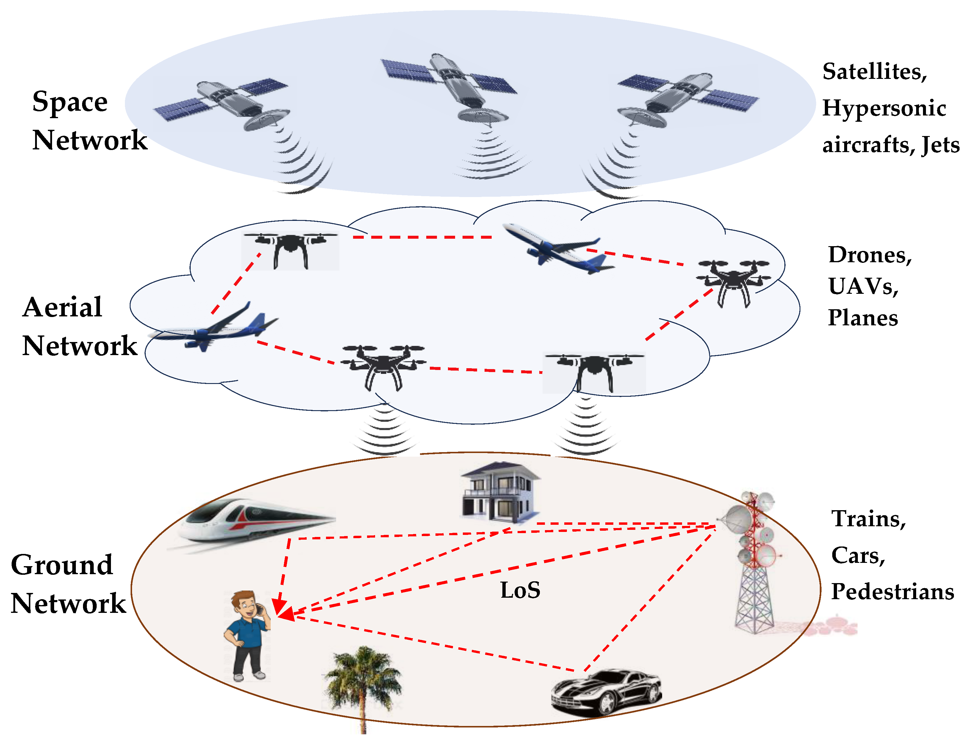
1. Introduction
1.1. Orthogonal Frequency Division Multiplexing (OFDM)
1.2. Orthogonal Time Frequency Space (OTFS)
1.3. Contribution
2. Related Work
3. System Model
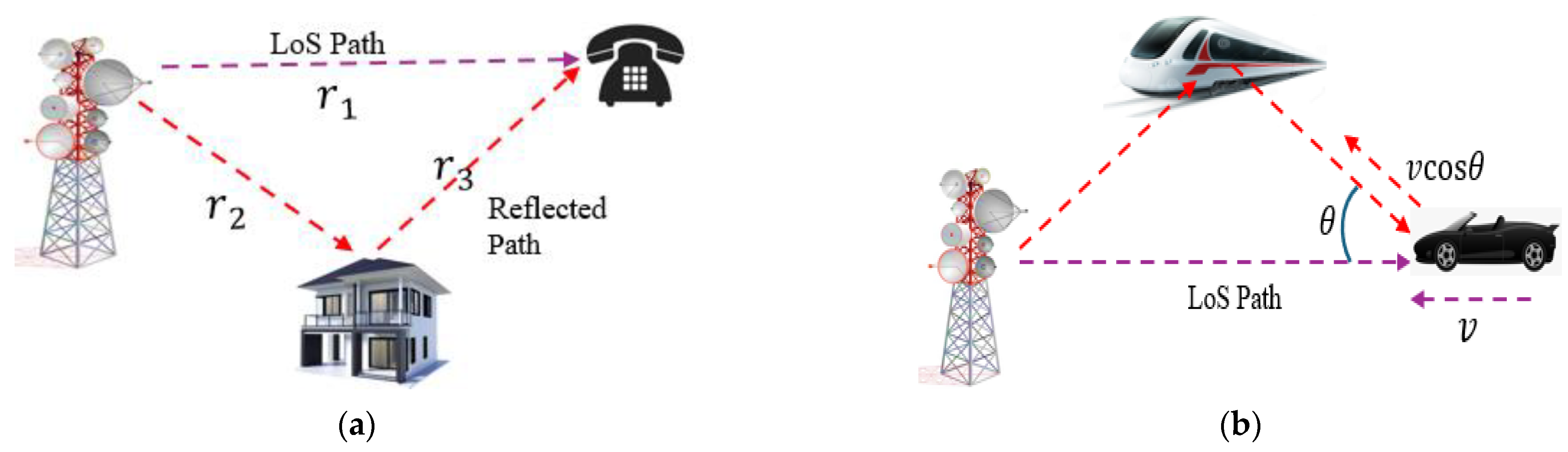
3.1. Received Signal and Channel Model
3.2. OTFS Modulation and Demodulation
4. Results and Discussion
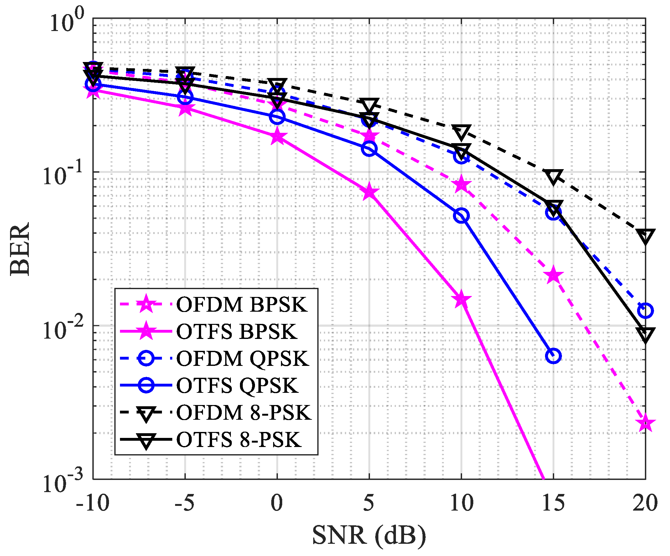
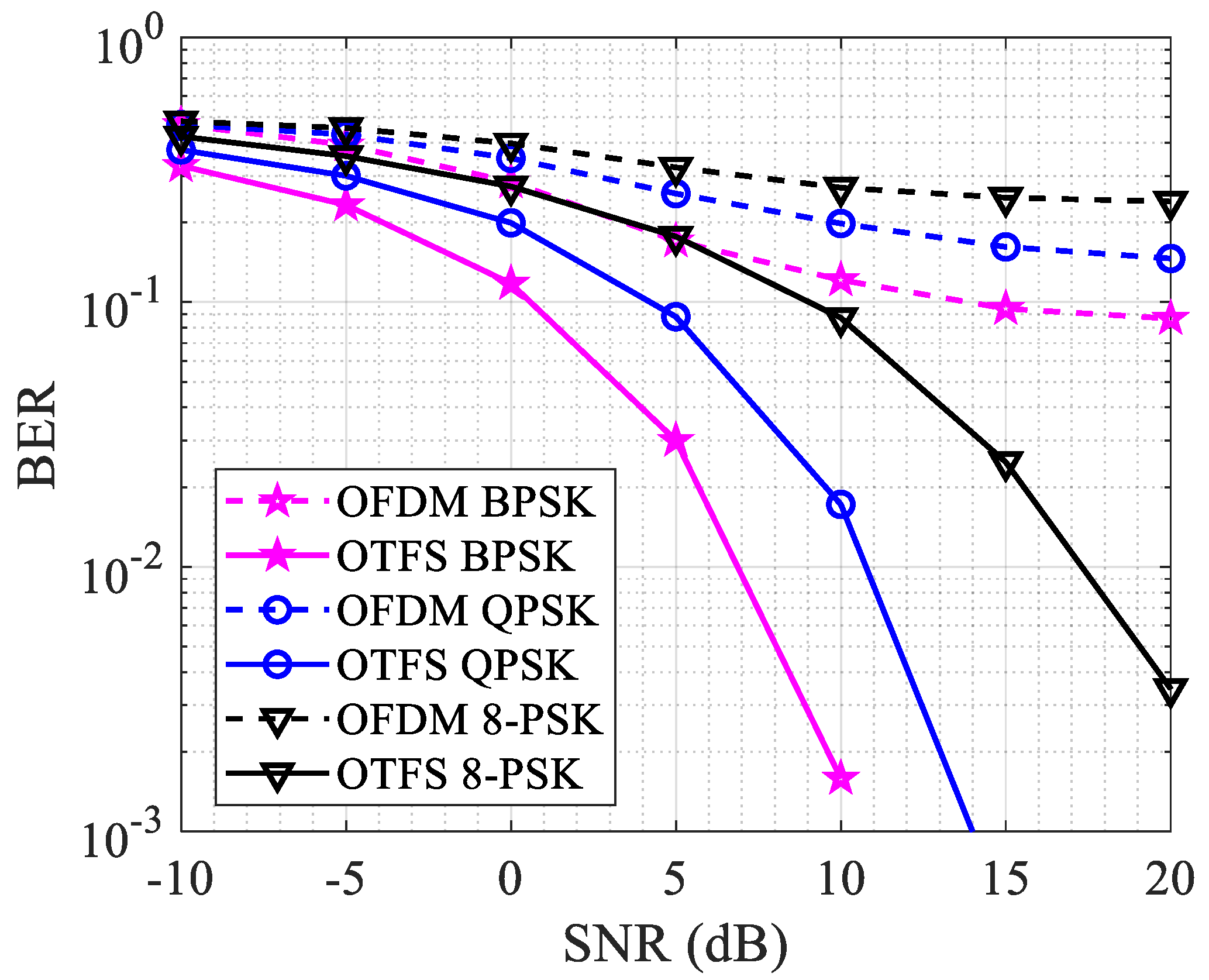
4.1. Channels with No Doppler Effects
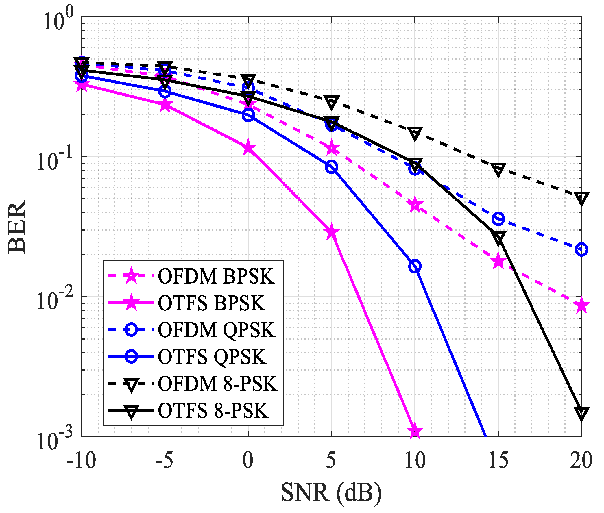
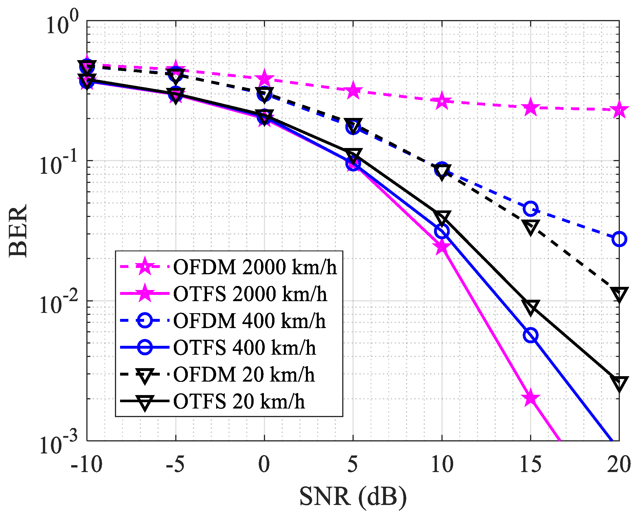
4.2. Channels with Doppler Effects
5. Conclusions
Author Contributions
Funding
Data Availability Statement
Conflicts of Interest
References
- Liu, J.; Shi, Y.; Kato, N. Space-Air-Ground Integrated Network: A Survey. IEEE Commun. Surv. Tutor. 2018, 20, 2714–2741. [Google Scholar] [CrossRef]
- Geraci, G.; Garcia-Rodriguez, A.; Azari, M.M.; Lozano, A.; Mezzavilla, M.; Chatzinotas, S.; Chen, Y.; Rangan, S.; Di Renzo, M. What Will the Future of UAV Cellular Communications Be? A Flight From 5G to 6G. IEEE Commun. Surv. Tutor. 2022, 24, 1304–1335. [Google Scholar] [CrossRef]
- Wang, T.; Proakis, J.G.; Masry, E.; Zeidler, J.R. Performance degradation of OFDM systems due to doppler spreading. IEEE Trans. Wirel. Commun. 2006, 5, 1422–1432. [Google Scholar] [CrossRef]
- Li, Y.; Wen, M.; Cheng, X.; Yang, L.Q. Index modulated OFDM with ICI self-cancellation. In Proceedings of the 2016 International Conference on Computing, Networking and Communications (ICNC), Kauai, HI, USA, 15–18 February 2016. [Google Scholar] [CrossRef]
- Geetha, C.; Vanitha, M.; Parimala, A.; Kalaiarasi, D. A Novel Channel Estimation Scheme for MIMO-OFDM Systems based on CDD. In Proceedings of the 5th International Conference on Inventive Computation Technologies, ICICT 2022—Proceedings, Lalitpur, Nepal, 20–22 July 2022; pp. 747–753. [Google Scholar] [CrossRef]
- Hong, Y.; Thaj, T.; Viterbo, E. Delay-Doppler Communications; Elsevier: Amsterdam, The Netherlands, 2022. [Google Scholar] [CrossRef]
- Lee, K.F.; Williams, D.B. A space-frequency transmitter diversity technique for OFDM systems. In Proceedings of the Globecom’00—IEEE. Global Telecommunications Conference—Conference Record (Cat. No. 00CH37137), San Francisco, CA, USA, 27 November–1 December 2000; pp. 1473–1477. [Google Scholar] [CrossRef]
- Lu, J.; Chen, X.; Liu, S.; Fan, P. Location-Aware Low Complexity ICI Reduction in OFDM Downlinks for High-Speed Railway Communication Systems with Distributed Antennas. In Proceedings of the 2016 IEEE 83rd Vehicular Technology Conference (VTC Spring), Nanjing, China, 15–18 May 2016; pp. 1–5. [Google Scholar] [CrossRef]
- Kaur, N.; Kumar, N. Comparative Analysis of ICI Self Cancellation Techniques for Wavelet OFDM Under Different Channels in Simulink. Wirel. Pers. Commun. 2019, 105, 1513–1525. [Google Scholar] [CrossRef]
- Idris, A.; Sabry, M.; Razak, N.I.A.; Yusof, A.L.; Mara Shah Alam, U. Fast Time-Varying Channels in MIMO-OFDM System Using Different Diversity Technique. In Proceedings of the 2013 IEEE Symposium on Wireless Technology and Applications (ISWTA), Kuching, Malaysia, 22–25 September 2013. [Google Scholar] [CrossRef]
- Okoyeigbo, O.; Okokpujie, K.; Noma-Osaghae, E.; Ndujiuba, C.U.; Shobayo, O.; Jeremiah, A. Comparative Study of MIMO-OFDM Channel Estimation in Wireless Systems. Int. Rev. Model. Simul. (IREMOS) 2018, 11, 158. [Google Scholar] [CrossRef]
- Pham, T.; Le-Ngoc, T.; Woodward, G.; Martin, P.A.; Phan, K.T. Equalization for MIMO-OFDM systems with insufficient cyclic prefix. In Proceedings of the IEEE Vehicular Technology Conference, Nanjing, China, 15–18 May 2016. [Google Scholar] [CrossRef]
- Hadani, R.; Rakib, S.; Tsatsanis, M.; Monk, A.; Goldsmith, A.J.; Molisch, A.F.; Calderbank, R. Orthogonal Time Frequency Space Modulation. In Proceedings of the 2017 IEEE Wireless Communications and Networking Conference (WCNC), San Francisco, CA, USA, 19–22 March 2017; pp. 1–6. [Google Scholar] [CrossRef]
- Raviteja, P.; Member, S.; Phan, K.T.; Hong, Y.; Member, S.; Viterbo, E. Interference Cancellation and Iterative Detection for Orthogonal Time Frequency Space Modulation. IEEE Trans. Wirel. Commun. 2018, 17, 6501. [Google Scholar] [CrossRef]
- Buzzi, S.; Caire, G.; Colavolpe, G.; D’Andrea, C.; Foggi, T.; Piemontese, A.; Ugolini, A. LEO Satellite Diversity in 6G Non-Terrestrial Networks: OFDM vs. OTFS. IEEE Commun. Lett. 2023, 27, 3013–3017. [Google Scholar] [CrossRef]
- Raviteja, P.; Phan, K.T.; Hong, Y.; Viterbo, E. Orthogonal time frequency space (OTFS) modulation based radar system. In Proceedings of the 2019 IEEE Radar Conference (RadarConf), Boston, MA, USA, 16 September 2019. [Google Scholar] [CrossRef]
- Hadani, R.; Rakib, S.; Molisch, A.F.; Ibars, C.; Monk, A.; Tsatsanis, M.; Delfeld, J.; Goldsmith, A.; Calderbank, R. Orthogonal Time Frequency Space (OTFS) modulation for millimeter-wave communications systems. In Proceedings of the 2017 IEEE MTT-S International Microwave Symposium (IMS), Honolulu, HI, USA, 4–9 June 2017; pp. 681–683. [Google Scholar] [CrossRef]
- Ramachandran, M.K.; Chockalingam, A. MIMO-OTFS in High-Doppler Fading Channels: Signal Detection and Channel Estimation. In Proceedings of the 2018 IEEE Global Communications Conference (GLOBECOM), Abu Dhabi, United Arab Emirates, 9–13 December 2018; pp. 206–212. [Google Scholar] [CrossRef]
- Shen, W.; Dai, L.; An, J.; Fan, P.; Heath, R.W. Channel Estimation for Orthogonal Time Frequency Space (OTFS) Massive MIMO. IEEE Trans. Signal Process. 2019, 67, 4204–4217. [Google Scholar] [CrossRef]
- Raviteja, P.; Phan, K.T.; Jin, Q.; Hong, Y.; Viterbo, E. Low-complexity iterative detection for orthogonal time frequency space modulation. In Proceedings of the IEEE Wireless Communications and Networking Conference, WCNC, Barcelona, Spain, 15–18 April 2018; pp. 1–6. [Google Scholar] [CrossRef]
- Yuan, W.; Li, S.; Wei, Z.; Cui, Y.; Jiang, J.; Zhang, H.; Fan, P. New delay Doppler communication paradigm in 6G era: A survey of orthogonal time frequency space (OTFS). China Commun. 2023, 20, 1–25. [Google Scholar] [CrossRef]
- Aldababsa, M.; Özyurt, S.; Kurt, G.K.; Kucur, O. A Survey on Orthogonal Time Frequency Space Modulation. IEEE Open J. Commun. Soc. 2024, 5, 4483–4518. [Google Scholar] [CrossRef]
- Xu, C.; Xiang, L.; An, J.; Dong, C.; Sugiura, S.; Maunder, R.G.; Yang, L.-L.; Hanzo, L. OTFS-Aided RIS-Assisted SAGIN Systems Outperform Their OFDM Counterparts in Doubly Selective High-Doppler Scenarios. IEEE Internet Things J. 2023, 10, 682–703. [Google Scholar] [CrossRef]
- Wei, Z.; Li, S.; Yuan, W.; Schober, R.; Caire, G. Orthogonal Time Frequency Space Modulation—Part I: Fundamentals and Challenges Ahead. IEEE Commun. Lett. 2023, 27, 4–8. [Google Scholar] [CrossRef]
- Lampel, F.; Member, S.; Alvarado, A.; Member, S.; Willems, F.M. Orthogonal Time Frequency Space Modulation: A Discrete Zak Transform Approach. Entropy 2021, 24, 1704. [Google Scholar] [CrossRef]
- Mathworks. OTFS Modulation. Available online: https://uk.mathworks.com/help/comm/ug/otfs-modulation.html (accessed on 17 December 2024).


| Parameter | Value |
|---|---|
| Number of Subcarriers (M) | 128 |
| Number of Sub-symbols per Frame (N) | 64 |
| Subcarrier Spacing | 480 kHz |
| Carrier Frequency | 100 GHz |
| Padding Length | 10 samples |
| Signal-to-Noise Ratio (SNR dB) | 30 dB |
| Mobility Scenarios and Application | 20–120 km/h (Cars, V2X, trains) 300–500 km/h (High Speed Trains and UAVs) 1000–2000 km/h (Jets) |
| Modulation Order | BPSK, QPSK, 8-PSK |
| Channel Estimation Method | Linear MMSE |
Disclaimer/Publisher’s Note: The statements, opinions and data contained in all publications are solely those of the individual author(s) and contributor(s) and not of MDPI and/or the editor(s). MDPI and/or the editor(s) disclaim responsibility for any injury to people or property resulting from any ideas, methods, instructions or products referred to in the content. |
© 2025 by the authors. Licensee MDPI, Basel, Switzerland. This article is an open access article distributed under the terms and conditions of the Creative Commons Attribution (CC BY) license (https://creativecommons.org/licenses/by/4.0/).
Share and Cite
Okoyeigbo, O.; Deng, X.; Imoize, A.L.; Shobayo, O. OTFS: A Potential Waveform for Space–Air–Ground Integrated Networks in 6G and Beyond. Telecom 2025, 6, 19. https://doi.org/10.3390/telecom6010019
Okoyeigbo O, Deng X, Imoize AL, Shobayo O. OTFS: A Potential Waveform for Space–Air–Ground Integrated Networks in 6G and Beyond. Telecom. 2025; 6(1):19. https://doi.org/10.3390/telecom6010019
Chicago/Turabian StyleOkoyeigbo, Obinna, Xutao Deng, Agbotiname Lucky Imoize, and Olamilekan Shobayo. 2025. "OTFS: A Potential Waveform for Space–Air–Ground Integrated Networks in 6G and Beyond" Telecom 6, no. 1: 19. https://doi.org/10.3390/telecom6010019
APA StyleOkoyeigbo, O., Deng, X., Imoize, A. L., & Shobayo, O. (2025). OTFS: A Potential Waveform for Space–Air–Ground Integrated Networks in 6G and Beyond. Telecom, 6(1), 19. https://doi.org/10.3390/telecom6010019