Abstract
Building Information Modeling (BIM) is a critical element for the “digitalization” of the construction industry and can be exploited for energy-driven renovation procedures of existing residences. Advancing beyond a BIM with data-capturing capabilities that are limited to building static information only requires sensor data streams related to indoor/outdoor ambient conditions, as well as to energy-consumption parameters of the residences. The data streams require the deployment of robust Wireless Sensor Networks (WSNs) that are able to capture and transmit real-time data to appropriate cloud-based renovation toolkits. The technology and topology of such networks are addressed herein. The paper sets the lines for similar installations that are required by the construction industry for collecting dynamic data, since it is based on the outcome of real-world WSN installations in pilot sites in three European countries, carried out in the context of a major collaborative BIM research project. An application example of the WSN data is also provided in the context of training occupant behavior models in order to demonstrate the use of the measured data.
1. Introduction
BIMERR (BIM-based holistic tools for Energy-driven Renovation of existing Residences) is a research and innovation program which started in 2018, supported by a consortium of 16 members, including EU companies and Universities, and co-funded by the European Union Horizon 2020 [1]. The target of the BIMERR project is to design and develop a renovation toolkit which will comprise tools to support renovation stakeholders, throughout the renovation process of existing buildings, from project conception to delivery. It comprises tools for the automated creation of enhanced Building Information Modeling (BIM), a renovation decision support system to aid the designer in exploring available renovation options, as well as a process management tool that will optimize the design and on-site construction process toward optimal coordination and minimization of renovation time and cost. At the heart of the BIMERR toolkit lies an Interoperability Framework which enforces semantic interoperability among BIMERR tools, as well as with third-party legacy Information Communication Technologies (ICTs) tools to enable seamless BIM creation and information exchange among Architecture, Engineering and Construction (AEC) stakeholders in an effort to enhance the rapid adoption of BIM in renovation of the existing EU building stock [2,3]. In this study, the BIMERR toolkit was validated and demonstrated in four buildings in three European Member States. Two buildings were used for pre-validation and implementation refinement, and the refined BIMERR toolkit supported the actual renovation design and works in the other two pilot buildings. The assessment and evaluation of the BIMERR toolkit after these real-life activities fed material into two supporting horizontal project activities: (i) dissemination and exploitation of project outcomes through the creation of best practice examples of BIMERR use that will guide further replication effort, and (ii) promotion of BIMERR outcome to the most relevant standardization bodies.
The availability and use of large volumes of BIM-generated data to gain knowledge that can be further exploited in various applications [4] in a BIM-based project by using machine learning (ML) and deep learning (DL) is a new research area of particular interest for the AEC industry [5,6]. BIM models for each stage can be developed from different data sources (e.g., designer inputs, CAD as-build, etc.), and then relevant data can be extracted from the BIM model in order make adaptive/smart decisions.
Early ML-based BIM research dealing with how the BIM process enhances the project-progress tracking was proposed in Reference [7]. Work in References [8,9,10] integrated cloud BIM, IoT and Data Mining (DM) into the digital twin framework, establishing a high degree of automation. Combining BIM and expert systems in order to provide a way to conduct autonomous safety risk identification is examined in Reference [11]. Predictive maintenance based on BIM, IoT and ML techniques to improve the facility management of existing building assets is examined in Reference [12].
The usability of dynamic monitoring and control for Building Energy Management Systems is presented in Reference [13] by integrating facilities, sensors and ML combined with simulation models, historical data and an intelligent controller. In Reference [14] is presented a BIM-based DM method that analyzes thermal performance of buildings with the help of BIM data; Heating, Ventilating and Air-Conditioning (HVAC); environmental conditions; and occupant behavior.
An extensive literature review on machine-learning applications to BIM is out of the scope of this paper; hence, the interested reader is referred to the excellent work presented in Reference [15].
The accuracy of the BIMERR energy Key Performance Indicator (KPI) values is highly affected by the level of detail of the input data, and recent studies have shown that the occupant-behavior data constitute the major cause of uncertainty [16]. Hence, a deeper understanding and proper modeling of the occupant behavior are of paramount importance. For capturing information that goes beyond static data of BIM, the BIMERR toolkit requires specific dynamic sensor data in order to generate occupant behavior (OB) models/profiles, provided in a standardized format (occupant behavior standardized XML-obXML) [17]. To this direction, the sensor data streams must be sourced from appropriate sensors and able to provide measurements for various parameters of interest, such as room air temperature and humidity, room occupancy, air conditioner’s status (on/off), air conditioner’s thermostat set-point temperature and operation mode (heating, cooling, fan, etc.), status of doors and windows (open/closed), weather conditions (including outdoor temperature and relative humidity, and wind speed and direction) and energy consumption.
The Wireless Sensor Network (WSN) is a suitable solution that is able to integrate the sensing and controlling of the environment in the context of the BIM and smart buildings. Some of the recent studies present different solutions as to how to design WSNs with regard to sensing coverage, measurements significance, network connectivity and spatial positioning of sensors. In Reference [18], the authors used genetic algorithms to improve WSNs’ location accuracy; in Reference [19], the authors proposed an evolutionary algorithm to calculate the maximum sensor coverage; in Reference [20], the authors proposed an information service and live sensing in order to supervise the building energy performance; and in Reference [21], the authors investigated how BIM could support smart buildings from the architecture plan to the building management and [22] demonstrated sensor data visualization in BIM for supporting complex decisions.
Applying machine-learning algorithms on the sensor-data streams provided by the WSNs that are designed for and installed in the pilot sites generates occupant-behavior profiles that mimic the inhabitants’ actions and contribute to the accuracy of energy performance estimation, using ML-enabled occupant behavior methods [23,24,25,26]. These profiles are subsequently used to project the building system (e.g., heating/cooling) utilization boundaries to maintain the comfort zone of the residents.
This paper addresses the deployment, technology, topology and cost of robust WSNs that are able to collect and transmit real-time data required from BIM renovation toolkits. It is based on real WSN installations, rather than simulated results, as in most cases reported in the open literature. As a consequence, it considers different field requirements, constraints and options at the BIMERR pilot sites, and, hence, it sets the lines for similar installations required by the construction industry for collecting dynamic data required for BIM and smart buildings.
The paper is organized as follows: Section 2 describes the principles of the Wireless Sensor Network (WSN) deployed in the pilot sites of the BIMERR project. Section 3 presents the topology of the BIMERR WSN. Section 4 provides details about the equipment, sensors and budget. Section 5 presents measured sensor data from the BIMERR pilots, and Section 6 describes the application of WSN data in the context of BIM for training occupant behavior models.
2. BIMERR Wireless Sensor Network Description
In the context of the BIMERR project, pilot Wireless Sensor Networks (WSNs) were deployed in apartments of pilot buildings located in Poland, Spain and Greece. The WSN of each apartment is an autonomous wireless network, based on the Z-Wave Radio Access Technology (RAT), and consists of several Z-Wave enabled sensors. The sensors exchange data over the Internet with the BIMERR Middleware via a local Gateway (one Gateway per apartment), as depicted in Figure 1.
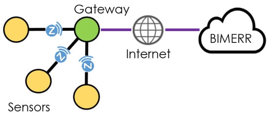
Figure 1.
BIMERR WSN concept.
The International Telecommunication Union (ITU) included the Z-Wave PHY and MAC layers as an option in the ITU-T G.9959 standard for wireless devices under 1 GHz [27]. The Z-Wave transceivers were supplied exclusively by Silicon Labs. Z-Wave operates in the unlicensed Industrial, Scientific and Medical (ISM) band, and the frequency used in Europe is 868.42 MHz. This band competes with some cordless telephones and other consumer electronics devices, but avoids interference with Wi-Fi, Bluetooth and other systems that operate in the “crowded” 2.4 GHz band. Z-Wave uses a source-routed mesh network architecture. In such networks, the source device (the “initiator”) uses the Z-Wave wireless interface to transmit messages which are relayed to the destination device of the network via neighboring Z-Wave devices in a “wave-like” fashion. In the indoor environments of the BIMERR project, the Z-Wave sensors can communicate with the Gateway by using intermediate sensors to actively route around and circumvent household obstacles or radio “dead spots” that might occur in the multipath environment. In this mesh network, a message from sensor A can be successfully delivered to Gateway G, even if the two devices are not within range, provided that a Sensor B can communicate both with A and G, as depicted in Figure 2. Therefore, a Z-Wave network can have a longer range than the radio of a single device.
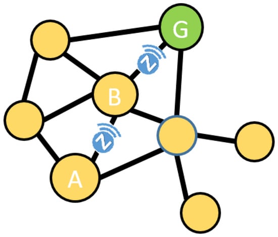
Figure 2.
Z-Wave mesh network concept.
When it comes to how many devices can be connected at once on the same mesh network or to the achievable data rates, Z-Wave can support up to 232 nodes (not considering the case of bridging networks), while ZigBee can support up to 65,000 nodes. Moreover, the max data transfer that can be achieved by Z-Wave is 100 Kbps, which is much lower compared to the 250 Kbps of ZigBee. However, since the number of nodes and data rates required by the project were rather low, and considering that ZigBee operates in the “crowded” 2.4 GHz band, Z-Wave was chosen as the most appropriate technical solution to be employed at the pilot sites.
In the BIMERR project, the Gateway of each apartment is the Primary Controller of the Z-Wave network. The network is identified by a unique Network ID. A Z-Wave device must first be “included” in the network in order to be able to exchange data over it (commissioning). Commissioning of a Z-Wave device needs to be performed only once during network setup. After successful commissioning, the device acquires the Network ID (4 bytes) and a Node ID (1 byte) by the Primary Controller.
3. BIMERR Wireless Sensor Network Topology
As described in the previous sections, the Gateway of each apartment makes the sensor-data streams available to the BIMERR Middleware via the Internet. Regarding the connection of the Gateways to the Internet, the following two technical solutions were employed:
- (1)
- WSN Architecture 1: In this pilot case, all Gateways were connected via Ethernet Cat 6 cables to a common Switch, and the Switch was connected to the Internet via a wireless 4G LTE Gateway. For the needs of local data processing of the sensor-data streams, a mini PC (Raspberry Pi 4 Model B with 4 GB RAM) was connected to the Switch. This PC was configured and remotely controlled for the needs of the project.
- (2)
- WSN Architecture 2: In these pilot cases, each Gateway had an autonomous internet connection either via a 4G LTE Gateway or via the apartment’s Internet Router (depending on the consent of the apartment’s tenants). Again, for local data processing of the sensor-data streams, a remotely controlled mini PC (Raspberry Pi 4 Model B with 2 GB RAM) was connected either to a local Switch or the Internet Router of the apartment.
The two aforementioned WSN architectures, regarding Internet connectivity, are depicted in Figure 3 and Figure 4, respectively.
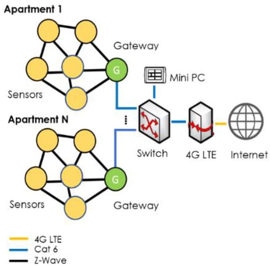
Figure 3.
WSN Architecture 1.
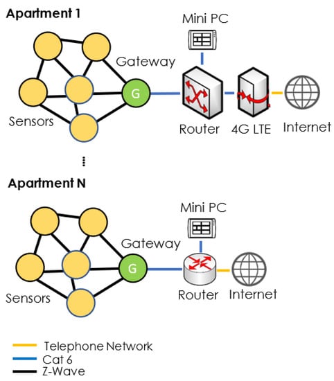
Figure 4.
WSN Architecture 2.
Regarding the installation of an apartment’s Gateway, the proposed location was the main corridor, i.e., the space of each apartment with a direct view of all other rooms. In this manner, the Gateway can have, in most cases, Line-of-Sight (LOS) communication with at least one sensor in each room, but even if LOS is not achieved due to the existence of walls and household obstacles, the distance between the Gateway and the sensors is the shortest possible. This was the recommended setup, inasmuch as this could be achieved during installation. This setup was finally achieved for the WSN pilot sites in Spain and Greece. However, this was not the case for the Polish pilot buildings, where the apartment Gateways should be placed at the staircase, just outside of, and very close to, the main entrance of each apartment. LOS conditions were not met in this case; however, since apartments are not very large, the frequency used by the Z-Wave was low (868.42 MHz) and the Z-Wave network was a mesh network, so data transfers between the Gateways and the sensors were accomplished with adequate signal strength (RSS). This was also justified with field tests prior to the installations.
The WSN topology for the apartments of each pilot site is depicted in Figure 5, Figure 6 and Figure 7. In these figures, “G” stands for the Gateway and “S” stands for any Z-Wave sensor of the WSN. For simplicity reasons, not all equipment and sensors installed in the apartments are depicted. A detailed analysis of the exact type and quantity of the equipment and sensors installed per apartment is provided in Section 4.
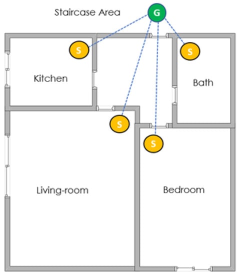
Figure 5.
WSN topology of the pilot apartments in Poland.
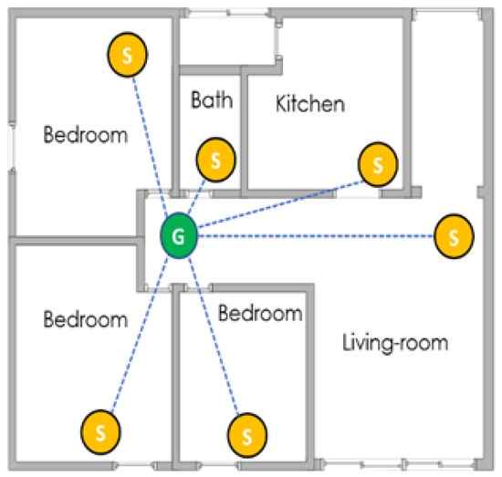
Figure 6.
WSN topology of the pilot apartments in Spain.
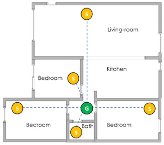
Figure 7.
WSN topology of the pilot apartments in Greece.
4. BIMERR Wireless Sensor Network Equipment, Sensors and Budget
Intensive site surveys, which were carried out by the supervising companies, addressed the exact type and quantity of the Z-Wave sensors/devices required at each pilot site, along with the communication and data processing equipment described in Figure 3 and Figure 4. The Z-Wave devices and sensors installed in the pilot sites are as follows:
- ▪
- Gateway: one per apartment.
- ▪
- Temperature/humidity/CO2 multi-sensor: one item per apartment, installed in the room occupied most of the day.
- ▪
- Motion/luminance sensor: one item per room.
- ▪
- Door/window sensor: one item per external door and external openable window pane.
- ▪
- Heat controller: one item per electric heater.
- ▪
- Wall plug: one item per electric device with considerable energy consumption, e.g., air condition units.
- ▪
- Power meter: one item per apartment for measuring the total energy. Extra sensors were required for electric devices with considerable energy consumption, where a wall plug was not applicable (e.g., cases of air-conditioning units with direct connection to the apartment’s mains panel).
- ▪
- Boiler thermostat: one item per apartment.
It must be noted that not all the aforementioned equipment was used in all apartments. The site surveys dictated the proper combinations of devices/sensors, as described in the following paragraphs [28].
4.1. Polish Pilot Site
This pilot site consists of two independent buildings, Building A and Building B. Both building have four floors with eight apartments per floor, of approximately 45 m2 each, i.e., 32 apartments each. For the needs of the BIMERR project, eight apartments were selected for the deployment of the WSN: five apartments from Building A and three from Building B. Each apartment consists of the following spaces: a living-room, a bedroom, a kitchen, a bathroom and a corridor (see Figure 5). The exact type and quantity of all Z-Wave sensors/devices installed per apartment are shown in Table 1. The common communication and data-processing equipment (see Figure 3) was installed at the basement of Building A and is shown in Table 2.

Table 1.
Polish pilot’s Z-Wave sensors per apartment.

Table 2.
Polish pilot’s communication and data-processing equipment for all apartments.
The total budget for the pilot site for the procurement, installation (including consumables) and configuration of all equipment and sensors, as well as for the 4G communication costs (2-year contract with a local MNO) was approximately 15 k€.
4.2. Spanish Pilot Site
This pilot building has 14 floors, with four apartments per floor, of approximately 50 m2 each. Each apartment consists of the following spaces: a living-room, three bedrooms, a kitchen, a bathroom and a corridor (see Figure 6). For the needs of the BIMERR project, six apartments were selected for the deployment of the WSN. The exact type and quantity of all Z-Wave sensors/devices installed per apartment is shown in Table 3. The communication and data processing equipment per apartment is shown in Table 4 (see Figure 4), however the LTE Gateway and the Switch were not required in apartments where tenants agreed in offering their Internet Router for the needs of the project.

Table 3.
Spanish pilot’s Z-Wave sensors per apartment.

Table 4.
Spanish pilot’s communication and data-processing equipment per apartment.
The total budget required for the procurement, installation (including consumables) and configuration of all equipment and sensors, as well as for the 4G communication costs (2-year contract with a local MNO), was approximately 19 k€.
4.3. Greek Pilot Site
This pilot site is a single apartment of 90 m2, which was practically used in the context of the project as a “pre-validation site”. The first WSN of the BIMERR project was deployed in this apartment, and all “lessons learned” were used afterward for the WSN installations of the other two pilot sites. This apartment consists of the following spaces: a living-room, three bedrooms, a kitchen, a bathroom and a corridor (see Figure 7). The exact type and quantity of all equipment and sensors installed in the apartment are shown in Table 5. The data-processing equipment is shown in Table 6. Moreover, it must be noted that, for capturing the air-conditioning status, thermostat set-point temperature and operation mode, a WiFi device was required (the IS-IR-WMP-1 of INTENSIS).

Table 5.
Greek pilot’s Z-Wave sensors per apartment.

Table 6.
Greek pilot’s data-processing equipment.
The total budget required for the procurement, installation (including consumables) and configuration of all equipment and sensors was approximately 2 k€.
5. Sensor Data from the Pilots
As detailed in Reference [29], the Middleware provides identity and data management services to facilitate a secure and resource-friendly flow of information among Gateways and other BIMERR applications. The offered services can be deployed on the cloud or edge inside buildings or apartments. The Middleware design is a modular subsystem customized to satisfy the BIMERR use cases, and it consists of the following components:
- Identity Provider: a central authentication server, a directory of user and application profiles, providing interfaces to authenticate them.
- Registry: a central repository containing metadata of Gateways and sensors.
- Data Processor: retrieves device metadata from Registry and automatically configures the available workflows for data routing and transformation.
- Storage: sensor data archival and retrieval.
- OTA Software Update and Monitoring: remote configuration and monitoring of the Gateway software.
- Device Connector: interoperability between Z-Wave sensors and data processor.
The Middleware acts as the sensor-data handler and repository, and it provides the Registry that contains metadata to query and access required items. The Middleware’s sensor-data storage services are microservices responsible for the storage and orchestration of sensor measurements data across the edge (building location) and BIMERR cloud.
As already mentioned, the accuracy of energy performance, as estimated by building energy performance simulation engines, such as EnergyPlus [30], is highly affected by the level of detail of its input data. Methods and models have been developed [19,31] to reduce the gap between simulated and measured building energy performance by representing occupant behavior in a standardized XML schema (obXML) [17]. The BIMERR PRUBS (Profiling Residents Usage Building Systems) component [28] applies machine-learning algorithms on sensor data streams to generate occupant-behavior profiles that mimic the inhabitants’ actions. These profiles are subsequently used to project the building system (e.g., heating/cooling) utilization boundaries to maintain the comfort zone of the residents. A high-level architecture of WSN, Middleware, PRUBS and BIMERR interoperability framework is illustrated in Figure 8.
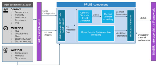
Figure 8.
BIMERR WSN, Middleware, PRUBS and Interoperability Framework architecture outline [28].
For the occupant-behavior model training, sensing and metering data are acquired by the WSN designed for and installed at each site. Weather data are received from external weather APIs. To receive the sensor data streams, PRUBS communicates with the BIMERR Middleware, which is responsible for the buildings’ sensor-data handling. The PRUBS output contains data-driven occupant-behavior models and populates a building level obXML file. That file is sent to the BIMERR Interoperability Framework [32] to be properly enriched and linked with other data, so that it can be used by other BIMERR applications. To conceptually gather the data mapping rules that must be performed to transform sensor data that are available through Middleware, and to input data that are meaningful for PRUBS, a Middleware-to-PRUBS sensor data wrapper was developed [28].
A demonstration of this wrapper is hereafter presented for the Greek pre-validation site and the two validation sites, i.e., the Spanish and Polish pilot. Figure 9 depicts the temperature profile and air-conditioning (AC) units’ power-consumption levels, as these were measured in the master bedroom of the pre-validation site and captured by the sensor data mapping. WSN data were retrieved for the period from 15 September to 25 September. As it can be seen, the temperature distribution fluctuates in response to the AC usage. In this case, the higher temperature values (over 25 °C) are well-captured during the high-power consumption days (indicated by the AC power spikes), while these are maintained at about 24–25 °C during the days that the power consumption remains relatively low.
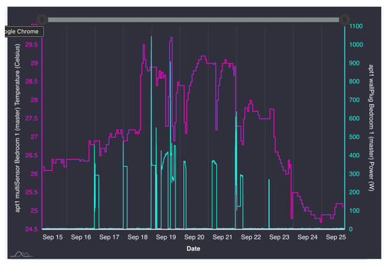
Figure 9.
Greek pilot site’s temperature sensor (left axis—purple color) and AC units power (right axis—green color) consumption data, 15 September 2021–25 September 2021.
Concerning the Spanish validation site, Figure 10 presents temperature data obtained by different sensors within the same apartment. Similar to the Greek pre-validation site, the obtained data indicate the seamless sensor-data flow for the period 5 November 2021–15 November 2021, during which the room temperature adapted in accordance with the occupants’ heating needs. Figure 11 demonstrates, respectively, the total power consumption measured for the whole apartment. An example of the sensor-temperature-data mapping for the second validation site (in Poland) is also shown in Figure 12 for the same period.
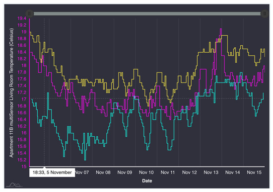
Figure 10.
Spanish pilot site’s temperature data from different sensors from the same apartment, 5 November 2021–15 November 2021.
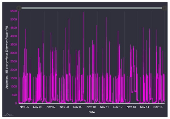
Figure 11.
Spanish-pilot-site apartment’s total power consumption data, 5 November 2021–15 November 2021.
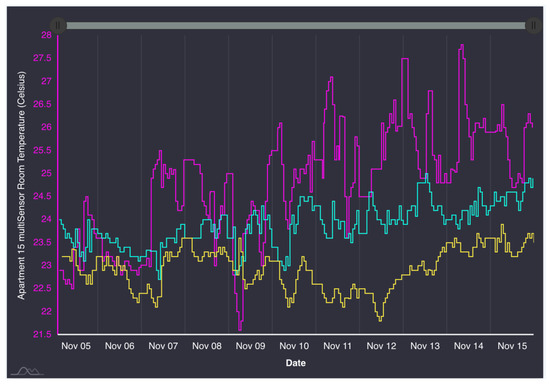
Figure 12.
Polish pilot site’s temperature data from different sensors in the same apartment, 5 November 2021–15 November 2021.
The aforementioned sensor data streams are subsequently used by the BIMERR toolkit to train the OB models, as discussed in the following section.
6. A Use-Case Example of WSN Measured Data for BIM: Training Occupant Behavior Models to Increase the Energy-Performance Estimation Accuracy
The methods applied to train occupant behavior models by PRUBS fall under three main categories: (1) the occupant thermal comfort, (2) the HVAC systems’ thermostat adjustment and (3) the profiling of other electric components’ usage. A brief description is provided in the following sections; meanwhile, for a detailed description, the reader should refer to Reference [28].
For the occupant thermal comfort modeling, the Gaussian Naïve Bayes method [33] is applied, a supervised machine-learning algorithm that follows the Bayes theorem, assuming conditional independence between the features, named Drivers in terms of obXML. Before training the model, an event-generation process is applied to populate the proper training events/dataset required as input to the ML model. In that process, certain preprocessing rules/steps are applied to sensed data that are stored in the PRUBS database. It is worth mentioning that other methods have also been evaluated as candidate alternatives to the Gaussian Naïve Bayes classifier for the thermal-comfort profiling, such as the Multinomial Naive Bayes, Logistic Regression, Random Forest, MLP Classifier (Neural Networks), SGD Classifier (Stochastic Gradient Descent), SVM (Support Vector Machines) and K-Neighbors Classification, [33]. A comparison was performed; however, such an analysis is beyond the scope of this paper.
For the HVAC systems’ thermostat-adjustment behaviors, two statistical modeling approaches that have been introduced in recent studies and seem to be the most applicable to residential buildings [23,24] are implemented in PRUBS. In the first approach [23], occupants are clustered into active, medium and passive users and multivariate logistic regression models are trained to predict the likelihood of a set-point increase or decrease. In the second approach [24], a three-parameter discrete Weibull distribution model is being developed and trained to represent occupants air-conditioning usage, considering indoor temperature, CO2 concentration and occupancy state as the model Drivers.
The Gaussian Processes [25] modeling approach was selected to extract information for the Other Electric Equipment Usage. Other Electric Equipment Usage includes all the electric components with a consumption that is not directly measured by any metering device but can be implicitly estimated by subtracting the electric HVAC loads consumption (measured) from the total electric consumption (measured) of the apartment. The Gaussian Processes (GPs) approach is a supervised machine-learning approach that predicts the mean value and standard deviation of the output (“Actions” in terms of obXML) given a set of inputs (“Drivers” in terms of obXML). This machine-learning modeling approach was selected because of its non-parametric nature, since it allows us to use the same models in all the experimental setups, regardless of the specifics of the HVAC systems, whereas, in the case of parametric models, a laborious manual model selection process has to be performed. Concerning its implementation to PRUBS, a trained Gaussian-Processes-based model predicts the mean and standard deviation of the Other-Electric-Equipment-Usage power consumption for each apartment at each time-step, given as input (“Drivers”) the following measured parameters: (1) hourly outdoor air temperatures in °C, relative humidity in %, and cloud coverage for the building’s location received from external weather APIs and stored in PRUBS private repository; (2) rooms’ (space) air temperature, the hourly air temperature for each space of the apartment received from the Middleware and mapped to the PRUBS data model; (3) event driven external windows and doors state data acquired from the Middleware mapped to the PRUBS data model and interpolated to provide hourly data; (4) hourly HVAC load-type power-consumption data received from the Middleware and aggregated to get the hourly HVAC total power consumption; (5) hourly total electric consumption of the apartment received from the Middleware; and (6) time-of-day and day-of-week data.
The performance evaluation of the trained models is based on the FIT metric, which is defined as follows:
where is the normalized root mean square error, the predicted value, the measured value and l is the number of training-set samples.
As an application example, Figure 13 shows for the Greek pre-validation site a snapshot of the populated occupant behavior model, as a result of the corresponding WSN data. Note that the first bunch of devices in the Greek building was on-boarded in October 2020, but, due to the pandemic and the fact that the building was unoccupied from October 2020 to March 2021, the lack of actual HVAC and other electric-equipment power-consumption data for that period made the evaluation of the trained algorithms biased. Nevertheless, they did reflect the actual status of the building and, in this case, co-simulation of the OB models with building energy-performance simulations estimated zero heating demands and thermal comfort boundaries that were significantly lower than the usual temperature set-point limits. Since April 2021, more reasonable sensor data have been collected, and during the summer months, the first non-zero HVAC power-consumption data became available. Based on the trained OB models for the aforementioned period, the corresponding file of Greek building was successfully updated.
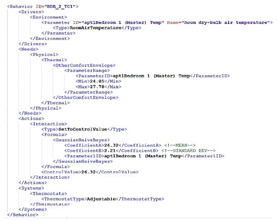
Figure 13.
Greek pilot site’s trained thermal comfort bounds and thermostat model.
7. Conclusions
The deployment, technology, topology and cost of robust real-world WSNs installations were discussed in the context of BIM. Pilot-site installations in three European countries were reported in the context of the European collaborative project BIMERR. The WSNs are able to collect and transmit real-time data, as required from the BIMERR renovation toolkits. They consider the different field requirements and options at the pilot sites, and, hence, the presented work can set the lines for similar installations by the construction industry for collecting dynamic data for BIM.
A use-case example of WSN measured data for BIM is also provided in terms of the application of WSN data for training occupant behavior models in order to increase the accuracy of energy-performance simulations.
Optimal WSN deployment in smart buildings by using BIM technology, i.e., integration of WSNs as part of BIM tools to exploit building information and automatically generate and visualize the deployment solutions, is an interesting problem that could be considered in future work. Furthermore, ML application to BIM on the full lifecycle of a project in order to learn and provide insights that support decision-making from design to operations is a very interesting open problem.
Author Contributions
Conceptualization, D.K. and G.A.; methodology, D.K., G.T. and G.G.; formal analysis, D.K., G.T., G.G.; writing—original draft preparation, D.K., G.T. and G.G.; writing—review and editing, G.A., G.T. and G.G. All authors have read and agreed to the published version of the manuscript.
Funding
The work in this paper was co-funded by the European Union Horizon 2020 Research and Innovation Programme, under grant agreement no. 820621.
Institutional Review Board Statement
Not applicable.
Informed Consent Statement
Not applicable.
Data Availability Statement
Not applicable.
Acknowledgments
The authors would like to thank all the BIMERR partners and, in particular, Budimex, Ferrovial, Conkat, FIT and Suite 5.
Conflicts of Interest
The authors declare no conflict of interest.
References
- BIM-Based Holistic Tools for Energy-Driven Renovation of Existing Residences—BIMERR. Available online: https://bimerr.eu/ (accessed on 1 December 2021).
- EU BIM Task Group. Available online: http://www.eubim.eu/ (accessed on 1 December 2021).
- National Building Specification. Working towards a Unified Approach to BIM in Europe. Available online: https://www.thenbs.com/knowledge/working-towards-a-unified-approach-to-bim-in-europe (accessed on 1 December 2021).
- Krijnen, T.; Tamke, M. Assessing Implicit Knowledge in BIM Models with Machine Learning; Springer International Publishing: Cham, Switzerland, 2015; pp. 397–406. [Google Scholar]
- Dreyfus, H.; Dreyfus, S.E.; Athanasiou, T. Mind over Machine; Free Press: New York, NY, USA, 1986. [Google Scholar]
- Hong, T.; Wang, Z.; Luo, X.; Zhang, W. State-of-the-art on research and applications of machine learning in the building life cycle. Energy Build. 2020, 212, 109831. [Google Scholar] [CrossRef] [Green Version]
- Golparvar-Fard, M.; Savarese, S.; Mora, F.P. Automated model-based recognition of progress using daily construction photographs and IFC-based 4D models. In Proceedings of the Construction Research Congress 2010: Innovation for Reshaping Construction Practice—Proceedings of the 2010 Construction Research Congress, Banff, AB, Canada, 8–10 May 2010; pp. 51–60. [Google Scholar]
- Pan, Y.; Zhang, L. Automated process discovery from event logs in BIM construction projects. Autom. Constr. 2021, 127, 103713. [Google Scholar] [CrossRef]
- Pan, Y.; Zhang, L. A BIM-data mining integrated digital twin framework for advanced project management. Autom. Constr. 2021, 124, 103564. [Google Scholar] [CrossRef]
- Zhang, L.; Wu, X.; Ding, L.; Skibniewski, M.; Lu, Y. Bim-Based Risk Identification System in Tunnel Construction. J. Civ. Eng. Manag. 2016, 22, 529–539. [Google Scholar] [CrossRef]
- Cheng, J.C.; Chen, W.; Chen, K.; Wang, Q. Data-driven predictive maintenance planning framework for MEP components based on BIM and IoT using machine learning algorithms. Autom. Constr. 2020, 112, 103087. [Google Scholar] [CrossRef]
- McGlinn, K.; Yuce, B.; Wicaksono, H.; Howell, S.; Rezgui, Y. Usability evaluation of a web-based tool for supporting holistic building energy management. Autom. Constr. 2017, 84, 154–165. [Google Scholar] [CrossRef] [Green Version]
- Garcia, L.C.; Kamsu-Foguem, B. BIM-oriented data mining for thermal performance of prefabricated buildings. Ecol. Inform. 2019, 51, 61–72. [Google Scholar] [CrossRef] [Green Version]
- Liu, Z.; Zhang, A.; Wang, W. A Framework for an Indoor Safety Management System Based on Digital Twin. Sensors 2020, 20, 5771. [Google Scholar] [CrossRef] [PubMed]
- Zabin, A.; González, V.A.; Zou, Y.; Amor, R. Applications of machine learning to BIM: A systematic literature review. Adv. Eng. Inform. 2021, 51, 101474. [Google Scholar] [CrossRef]
- D’Oca, S.; Fabi, V.; Corgnati, S.P.; Andersen, R.K. Effect of thermostat and window opening occupant behavior models on energy use in homes. Build. Simul. 2014, 7, 683–694. [Google Scholar] [CrossRef]
- Hong, T.; D’Oca, S.; Taylor-Lange, S.C.; Turner, W.J.; Chen, Y.; Corgnati, S.P. An ontology to represent energy-related occupant behavior in buildings. Part II: Implementation of the DNAS framework using an XML schema. Build. Environ. 2015, 94, 196–205. [Google Scholar] [CrossRef] [Green Version]
- Zhou, H.; Hu, J.; Wu, H.; Guo, C. Indoor positioning research based on wireless sensor network topology optimization. In Proceedings of the IEEE 2019 Chinese Automation Congress (CAC), Hangzhou, China, 22–24 November 2019. [Google Scholar]
- Yoon, Y.; Kim, Y. An Efficient Genetic Algorithm for Maximum Coverage Deployment in Wireless Sensor Networks. IEEE Trans. Cybern. 2013, 43, 1473–1483. [Google Scholar] [CrossRef] [PubMed]
- Wang, H.; Gluhak, A.; Meissner, S.; Tafazolli, R. Integration of BIM and Live Sensing Information to Monitor Building Energy Performance. In Proceedings of the 30th CIB W78 International Conference, Beijing, China, 9–12 October 2013. [Google Scholar]
- Zhang, J.; Seet, B.-C.; Lie, T.T. Building Information Modelling for Smart Built Environments. Buildings 2015, 5, 100–115. [Google Scholar] [CrossRef] [Green Version]
- Chang, K.-M.; Dzeng, R.-J.; Wu, Y.-J. An Automated IoT Visualization BIM Platform for Decision Support in Facilities Management. Appl. Sci. 2018, 8, 1086. [Google Scholar] [CrossRef] [Green Version]
- Yan, D.; O’Brien, W.; Hong, T.; Feng, X.; Gunay, H.B.; Tahmasebi, F.; Mahdavi, A. Occupant behavior modeling for building performance simulation: Current state and future challenges. Energy Build. 2015, 107, 264–278. [Google Scholar] [CrossRef] [Green Version]
- Gaetani, I.; Hoes, P.J.; Hensen, J.L. Ocupant behavior in building energy simulation: Towards a fit-for-purpose modeling strategy. Energy Build. 2016, 121, 188–204. [Google Scholar] [CrossRef]
- Amasyali, K.; El-Gohary, N. Machine learning for occupant-behavior-sensitive cooling energy consumption prediction in office buildings. Renew. Sustain. Energy Rev. 2021, 142, 110714. [Google Scholar] [CrossRef]
- Jia, M.; Srinivasan, R.S.; Raheem, A. From occupancy to occupant behavior: An analytical survey of data acquisition technologies, modeling methodologies and simulation coupling mechanisms for building energy efficiency. Renew. Sustain. Energy Rev. 2017, 68, 525–540. [Google Scholar] [CrossRef]
- Recommendation ITU-T, G.9959: Short Range Narrow-Band Digital Radiocommunication Transceivers—PHY and MAC Layer Specifications (Z-Wave). Available online: https://www.itu.int/rec/T-REC-G.9959-201501-I/en (accessed on 26 January 2021).
- BIMERR Deliverable D5.8 ‘Building Resident Energy-Related Behavior Profiling Framework 2’. 2020. Available online: https://bimerr.eu/ (accessed on 26 January 2021).
- BIMERR Deliverable D3.6 ‘BIMERR System Architecture 2nd version’. 2021. Available online: https://bimerr.eu/ (accessed on 26 January 2021).
- Crawley, D.B.; Lawrie, L.K.; Winkelmann, F.C.; Buhl, W.; Huang, Y.; Pedersen, C.O.; Strand, R.K.; Liesen, R.J.; Fisher, D.E.; Witte, M.J.; et al. EnergyPlus: Creating a new-generation building energy simulation program. Energy Build. 2001, 33, 319–331. [Google Scholar] [CrossRef]
- EBC Annex 66. Final Report-Definition and Simulation of Occupant Behavior in Buildings. 2018. Available online: http://annex66.org/sites/default/files/2018FinalReport/Annex%2066%20Final%20Report%20-%20read.pdf (accessed on 26 January 2021).
- BIMERR Deliverable D4.9. Integrated BIMERR Interoperability Framework 2. 2021. Available online: https://ploutos-h2020.eu/wp-content/uploads/2021/09/Ploutos_D4.4-Initial-agri-food-data-sharing-reference-architecture.pdf (accessed on 26 January 2021).
- Rasmussen, C.E.; Williams, C.K. Gaussian Processes for Machine Learning; The MIT Press: Cambridge, MA, USA, 2006; Volume 38, pp. 715–719. [Google Scholar]
Publisher’s Note: MDPI stays neutral with regard to jurisdictional claims in published maps and institutional affiliations. |
© 2022 by the authors. Licensee MDPI, Basel, Switzerland. This article is an open access article distributed under the terms and conditions of the Creative Commons Attribution (CC BY) license (https://creativecommons.org/licenses/by/4.0/).