
Designing Smart Electromagnetic Environments for Next-Generation Wireless Communications

 , ,
, , 
 ,
,  ,
, 
 and
and 
Abstract
:1. Introduction and Motivation
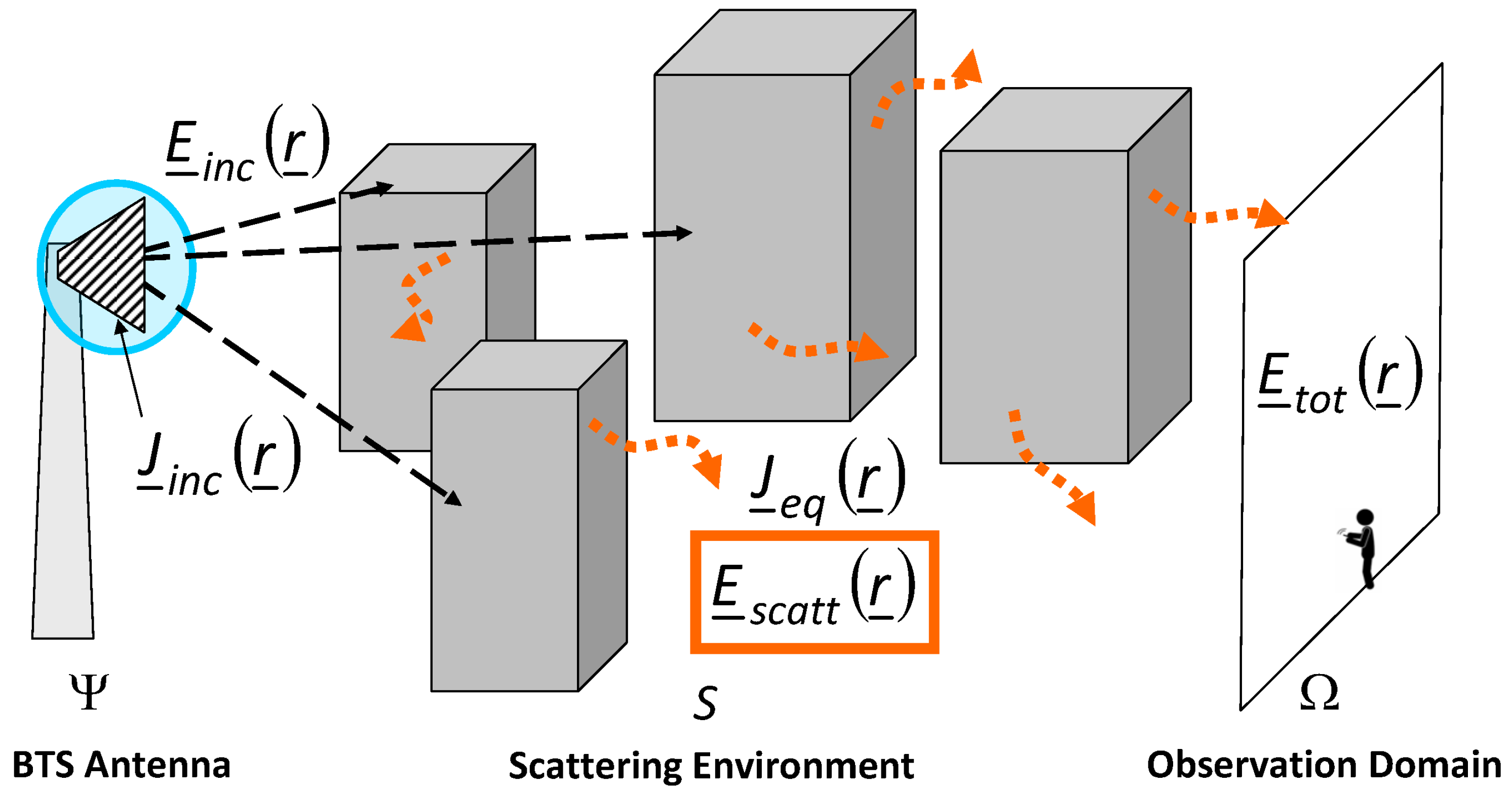
2. Mathematical Formulation
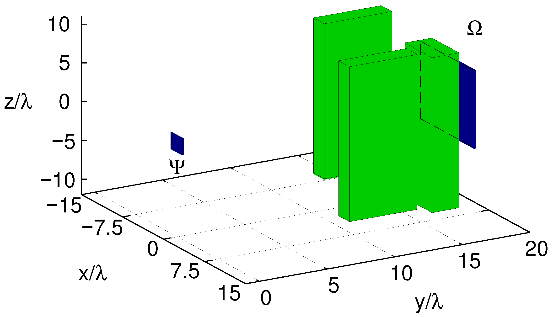
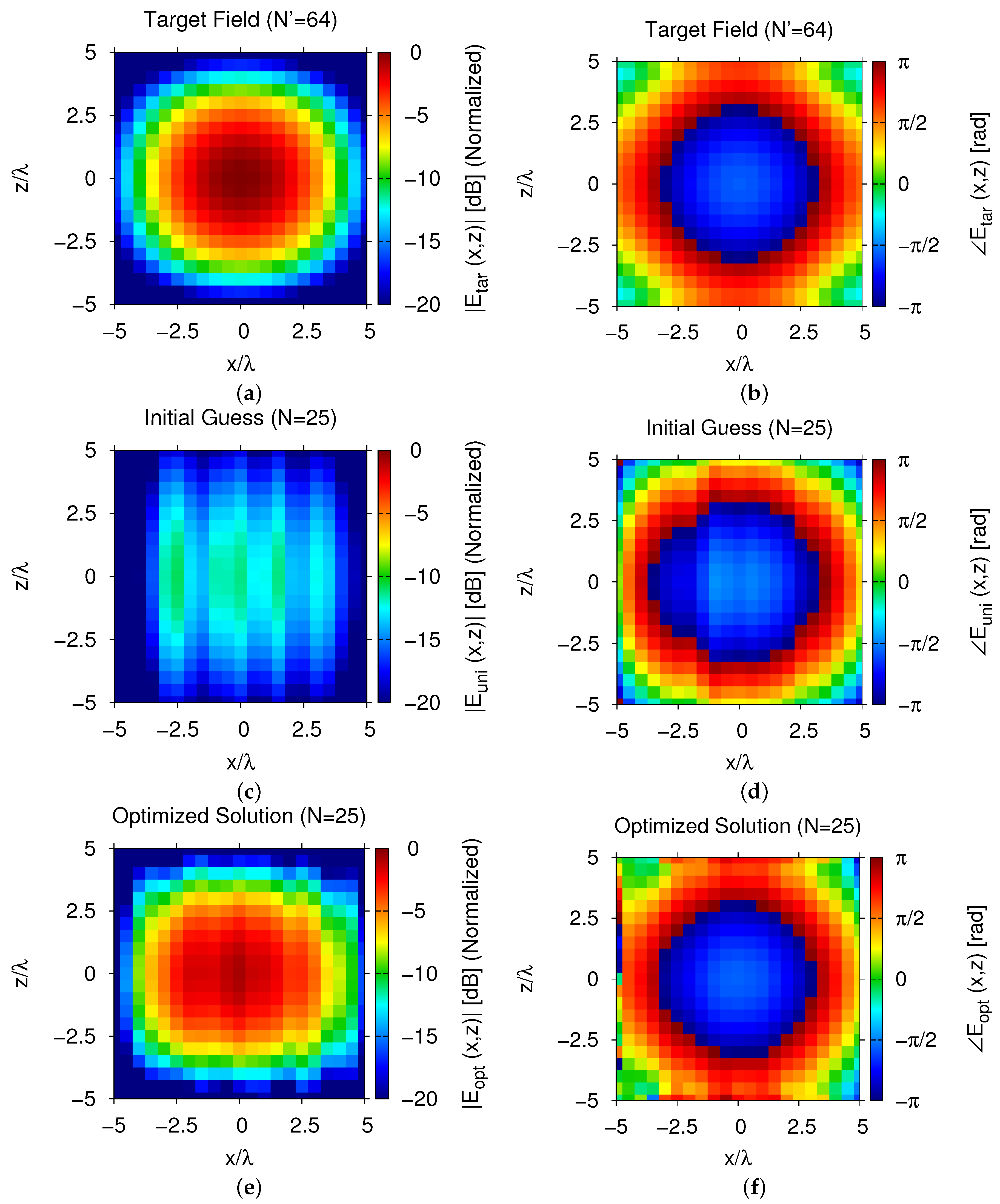
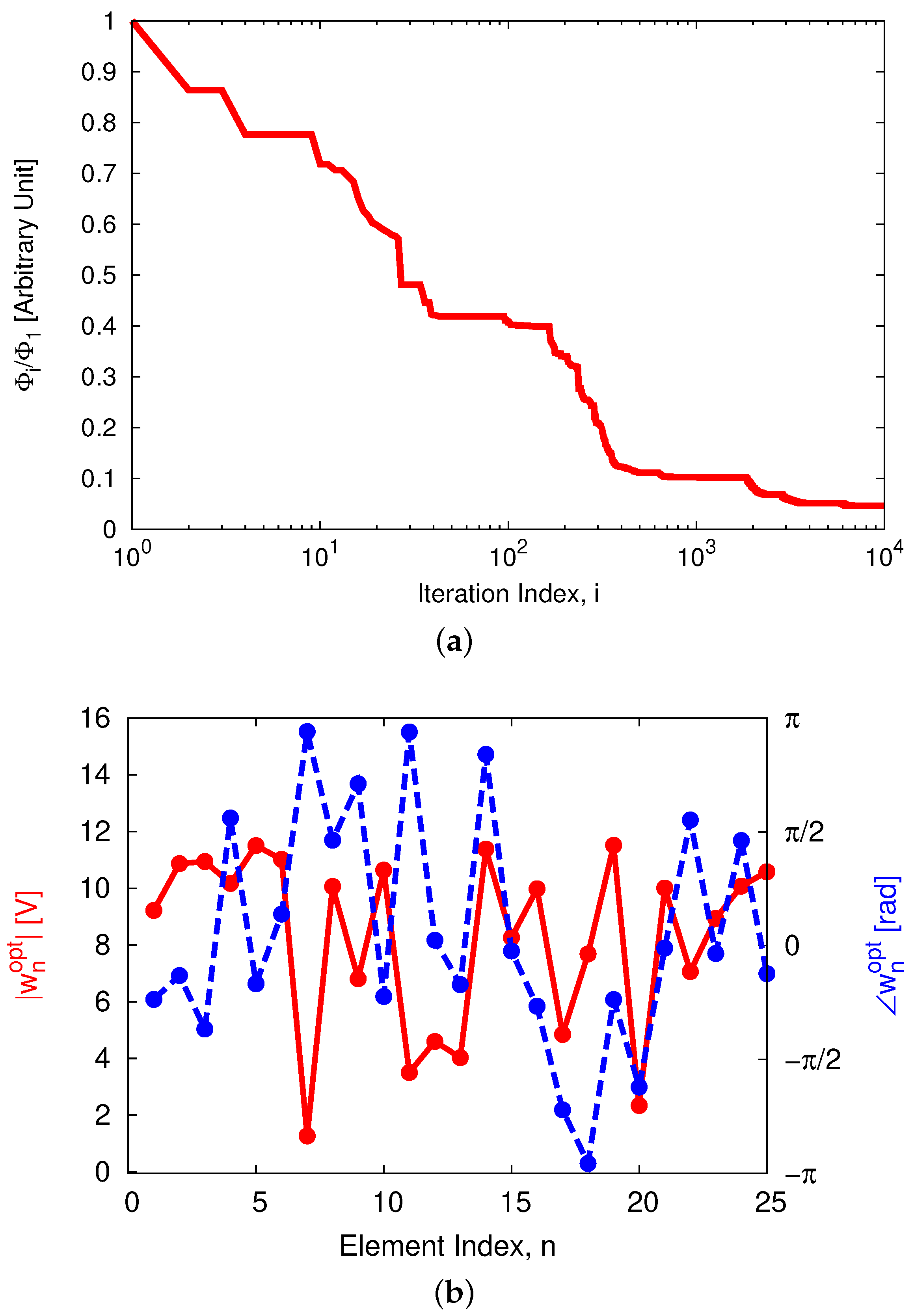
3. Numerical Assessment
4. Conclusions
Author Contributions
Funding
Institutional Review Board Statement
Informed Consent Statement
Data Availability Statement
Conflicts of Interest
References
- Liu, D.; Hong, W.; Rappaport, T.S.; Luxey, C.; Hong, W. What will 5G antennas and propagation be? IEEE Trans. Antennas Propag. 2017, 65, 6205–6212. [Google Scholar] [CrossRef]
- Akyildiz, I.F.; Kak, A.; Nie, S. 6G and beyond: The future of wireless communications systems. IEEE Access 2020, 8, 133995–134030. [Google Scholar] [CrossRef]
- Nawaz, S.J.; Sharma, S.K.; Wyne, S.; Patwary, M.N. Asaduzzaman Quantum machine learning for 6G communication networks: State-of-the-art and vision for the future. IEEE Access 2019, 7, 46317–46350. [Google Scholar] [CrossRef]
- Viswanathan, H.; Mogensen, P.E. Communications in the 6G era. IEEE Access 2020, 8, 57063–57074. [Google Scholar] [CrossRef]
- Yaacoub, E.; Alouini, M. A key 6G challenge and opportunity—Connecting the base of the pyramid: A survey on rural connectivity. Proc. IEEE 2020, 108, 533–582. [Google Scholar] [CrossRef] [Green Version]
- Bariah, L.; Mohjazi, L.; Muhaidat, S.; Sofotasios, P.C.; Kurt, G.K.; Yanikomeroglu, H.; Dobre, O.A. A prospective look: Key enabling technologies, applications and open research topics in 6G networks. IEEE Access 2020, 8, 174792–174820. [Google Scholar] [CrossRef]
- Ziegler, V.; Viswanathan, H.; Flinck, H.; Hoffmann, M.; Raisanen, V.; Hatonen, K. 6G architecture to connect the worlds. IEEE Access 2020, 8, 173508–173520. [Google Scholar] [CrossRef]
- Chowdhury, M.Z.; Shahjalal, M.; Ahmed, S.; Jang, Y.M. 6G wireless communication systems: Applications, requirements, technologies, challenges, and research directions. IEEE Open J. Commun. Soc. 2020, 1, 957–975. [Google Scholar] [CrossRef]
- Grande, M.; Bianco, G.V.; Laneve, D.; Capezzuto, P.; Petruzzelli, V.; Scalora, M.; Prudenzano, F.; Bruno, G.; D’Orazio, A. Optically transparent wideband CVD graphene-based microwave antennas. Appl. Phys. Lett. 2018, 112, 251103. [Google Scholar] [CrossRef]
- Rocca, P.; Oliveri, G.; Mailloux, R.J.; Massa, A. Unconventional phased array architectures and design methodologies—A review. Proc. IEEE 2016, 104, 544–560. [Google Scholar] [CrossRef]
- Herd, J.S.; Conwey, M.D. The evolution to modern phased array architectures. Proc. IEEE 2016, 104, 519–529. [Google Scholar] [CrossRef]
- Oliveri, G.; Gottardi, G.; Robol, F.; Polo, A.; Poli, L.; Salucci, M.; Chuan, M.; Massagrande, C.; Vinetti, P.; Mattivi, M.; et al. Co-design of unconventional array architectures and antenna elements for 5G base stations. IEEE Trans. Antennas Propag. 2017, 65, 6752–6767. [Google Scholar] [CrossRef]
- Mailloux, R.J. Phased Array Antenna Handbook, 3rd ed.; Artech House: Norwood, MA, USA, 2018. [Google Scholar]
- Oliveri, G.; Gottardi, G.; Massa, A. A new meta-paradigm for the synthesis of antenna arrays for future wireless communications. IEEE Trans. Antennas Propag. 2019, 67, 3774–3788. [Google Scholar] [CrossRef]
- Xu, C.; Yang, L.; Zhang, P. Practical backscatter communication systems for battery-free internet of things: A tutorial and survey of recent research. IEEE Signal Proc. Mag. 2018, 35, 16–27. [Google Scholar] [CrossRef]
- Basar, E.; Di Renzo, M.; De Rosny, J.; Debbah, M.; Alouini, M.-S.; Zhang, R. Wireless communications through reconfigurable intelligent surfaces. IEEE Access 2019, 7, 116753–116773. [Google Scholar] [CrossRef]
- Di Renzo, M.; Song, J. Reflection probability in wireless networks with metasurface-coated environmental objects: An approach based on random spatial processes. EURASIP J. Wirel. Commun. Netw. 2019, 99, 1–15. [Google Scholar] [CrossRef]
- Di Renzo, M.; Debbah, M.; Phan-Huy, D.-T.; Zappone, A.; Alouini, M.-S.; Yuen, C.; Sciancalepore, V.; Alexandropoulos, G.C.; Hoydis, J.; Gacanin, H.; et al. Smart radio environments empowered by reconfigurable AI meta-surfaces: An idea whose time has come. EURASIP J. Wirel. Commun. Netw. 2019, 129, 1–20. [Google Scholar] [CrossRef] [Green Version]
- Pengnoo, M.; Barros, M.T.; Wuttisittikulkij, L.; Butler, B.; Davy, A.; Balasubramaniam, S. Digital twin for metasurface reflector management in 6G terahertz communications. IEEE Access 2020, 8, 114580–114596. [Google Scholar] [CrossRef]
- Salucci, M.; Li, B.; Benoni, A.; Rocca, P.; Massa, A. Smart EM environment as enabling technology for future wireless systems. In Proceedings of the 14th International Congress on Artificial Materials for Novel Wave Phenomena (Metamaterials’ 2020), New York, NY, USA, 28 September–3 October 2020; pp. 48–50. [Google Scholar]
- Bertero, M.; Boccacci, P. Introduction to Inverse Problems in Imaging; IOP Press: Bristol, UK, 1998. [Google Scholar]
- Rocca, P.; Benedetti, M.; Donelli, M.; Franceschini, D.; Massa, A. Evolutionary optimization as applied to inverse problems. Inverse Probl. 2009, 25, 1–41. [Google Scholar] [CrossRef] [Green Version]
- Robert, A. Dielectric permittivity of concrete between 50 MHz and 1 GHz and GPR measurements for building materials evaluation. J. Appl. Geophys. 1998, 40, 89–94. [Google Scholar] [CrossRef]
- Altair Feko. Available online: https://www.altair.com/feko/ (accessed on 10 May 2021).


| Scatterer | Size | Barycenter |
|---|---|---|
| k | [] | [] |
| 1 | ||
| 2 | ||
| 3 |
Publisher’s Note: MDPI stays neutral with regard to jurisdictional claims in published maps and institutional affiliations. |
© 2021 by the authors. Licensee MDPI, Basel, Switzerland. This article is an open access article distributed under the terms and conditions of the Creative Commons Attribution (CC BY) license (https://creativecommons.org/licenses/by/4.0/).
Share and Cite
Massa, A.; Benoni, A.; Da Rù, P.; Goudos, S.K.; Li, B.; Oliveri, G.; Polo, A.; Rocca, P.; Salucci, M. Designing Smart Electromagnetic Environments for Next-Generation Wireless Communications. Telecom 2021, 2, 213-221. https://doi.org/10.3390/telecom2020014
Massa A, Benoni A, Da Rù P, Goudos SK, Li B, Oliveri G, Polo A, Rocca P, Salucci M. Designing Smart Electromagnetic Environments for Next-Generation Wireless Communications. Telecom. 2021; 2(2):213-221. https://doi.org/10.3390/telecom2020014
Chicago/Turabian StyleMassa, Andrea, Arianna Benoni, Pietro Da Rù, Sotirios K. Goudos, Baozhu Li, Giacomo Oliveri, Alessandro Polo, Paolo Rocca, and Marco Salucci. 2021. "Designing Smart Electromagnetic Environments for Next-Generation Wireless Communications" Telecom 2, no. 2: 213-221. https://doi.org/10.3390/telecom2020014
APA StyleMassa, A., Benoni, A., Da Rù, P., Goudos, S. K., Li, B., Oliveri, G., Polo, A., Rocca, P., & Salucci, M. (2021). Designing Smart Electromagnetic Environments for Next-Generation Wireless Communications. Telecom, 2(2), 213-221. https://doi.org/10.3390/telecom2020014