1. Introduction
Today’s increased energy consumption and problems related to climate change are prerequisites for the search for ecological and sustainable energy solutions. Among them, biomass is the most preferred renewable energy source, offering both a cost-effective alternative to fossil fuels and efficient waste management [
1]. The combustion of available waste biomass provides an opportunity to enhance the efficiency of the combustion process and has a corresponding positive environmental impact compared to various conventional solid and liquid fuels [
2]. Some studies show that the sustainable use of biomass can lead to a reduction in greenhouse gases and support the transition to a green economy [
3,
4]. Opportunities for optimizing biorefinery operations and implementing new technologies in the biofuel sector are also part of the path toward reducing the ecological footprint of energy-intensive industries [
5].
In recent years, there has been a global increase in the use of biomass in heating installations. For example, the European Union has applied practices to actively promote a reduction in fossil fuels and support the transition to carbon-neutral economies, as presented in [
6]. Pellets made from “raw” waste biomass are among the preferred ecological fuels due to their high energy density and ease of transportation and subsequent storage [
7]. Some studies show that the sustainable production of bio-pellets from various biomass sources can lead to a significant reduction in carbon footprint and reduce harmful impacts on the environment [
8]. Mixed wood and agro-waste pellets have a significantly lower carbon footprint compared to fossil fuels, which is in line with modern life cycle analysis (LCA) studies. In this way, their potential as an alternative energy source for domestic heating is confirmed. Additionally, biomass gasification has been identified as a potentially effective solution for small heating and energy installations [
9]. Gas obtained through gasification has a range of applications for the combined production of energy. The development of new methods for optimizing bio-briquetting and improving the characteristics of bio-pellets is key to increasing energy efficiency and sustainability [
10]. In addition to addressing the technical and environmental performance of mixed biomass pellets, understanding their market acceptance is essential for ensuring successful integration into residential heating applications. Although mixed pellets demonstrate advantageous combustion characteristics—such as a high calorific value, reduced ash content, and lower emissions—their adoption depends largely on consumer priorities and purchasing behavior. To explore this aspect, the present study includes a targeted market analysis aimed at assessing user preferences and the key factors influencing product selection. The resulting data provide a foundation for aligning product development with market needs, thereby supporting the practical implementation and broader uptake of mixed biomass pellets as a viable alternative fuel.
The direct combustion of raw waste biomass is typically carried out in boilers of various sizes (both industrial and domestic boilers). Modern boilers are highly efficient, allowing for the automation of the combustion process and providing options to burn one or more types of biofuels [
11]. Depending on their design, these boilers can be adapted for the combustion of pellets made from various types of wood, wood chips, agro-pellets, and other types of biomass [
12]. The primary goal of modern boilers is to achieve the most complete combustion of the input material, with minimal losses and reduced emissions of carbon monoxide (CO), nitrogen oxides (NOx), and other particulate matter [
13]. The quality of the combustion process in boilers depends on several parameters—the fuel composition (moisture content, ash content, and the chemical composition of the biomass), the temperature regime in the combustion chamber (the optimal temperature is crucial for complete combustion and reducing harmful emissions), the distribution of airflows (proper distribution reduces the formation of undesirable emissions and ensures efficient oxidation), and the dynamics of gas flows [
14,
15]. Wood pellets are among the most common forms used in biomass heating, but in recent years, there has been a growing interest in using pellets made by mixing various organic raw materials [
16,
17]. Innovations in electrostatic filter technology allow for significant reductions in particulate matter and NOx emissions in small heating installations [
18,
19]. The use of additives can enhance combustion efficiency and reduce the amount of emitted pollutants [
20,
21].
The mixing of different types of biomass in pellet production is essential for modern energetics, as it contributes to the optimization of combustion properties, since combining raw materials with different moisture and ash contents can improve combustion efficiency and reduce the formation of ash deposits in boilers [
22,
23]. In addition, mixing results in an increased energy density, since some plant waste has a lower energy value than wood; however, when appropriately combined, a balanced fuel with good combustion characteristics can be achieved [
24,
25]. This process also creates conditions for reducing production costs by utilizing agro-pellets and agricultural waste as additive raw materials, which lowers the cost of the final product [
26]. Furthermore, the mechanical properties of pellets can also be improved—certain materials, like pure wood chips, bind better during pelletization, while others, such as straw, may require additives or mixing with better-binding raw materials [
27,
28]. Mixing biomass raw materials can reduce harmful emissions, as the proper combination of biomass reduces gases like NOx and SO
2. Mixed pellets represent an important step in the development of renewable energy sources, providing an opportunity for the rational use of biomass and contributing to better development in the energy sector [
29,
30,
31,
32,
33,
34,
35].
Computational fluid dynamics can be used to improve the combustion process in biomass burning in different types of boilers. This approach allows for the detailed modeling of combustion processes and heat transfer and tracking the behavior and characteristics of flue gases, providing a better predictability of the combustion process and the possibility of emissions reduction [
36,
37].
One of the leading software products for numerical modeling and subsequent analysis is ANSYS CFX ver. 2021 R1, which enables the efficient modeling of complex aerodynamic and thermal processes in combustion chambers. This software allows for analyses of the temperature distribution and heat flow within the combustion chamber, the concentration of harmful gases (such as CO, NOx, and SO
2), the optimization of air supply methods and ratios for efficient combustion, and the impacts of different types of biomass on the combustion process [
38,
39]. CFD modeling is particularly useful for studying the combustion of mixed pellets, as it enables the assessment of how different components affect combustion efficiency and emissions. For example, mixing wood and agricultural waste can create a balanced fuel composition that reduces the formation of undesirable emissions and enhances the energy efficiency of the process [
40,
41]. The use of CFD in biomass boilers allows for virtual experiments, reducing the costs of physical testing and accelerating the improvement of design parameters for combustion chambers [
42,
43]. Furthermore, simulation results can be used to develop more efficient combustion strategies and improve boiler design [
44,
45,
46]. While interest in biomass fuels has grown significantly, systematic investigations into the combustion behavior of blended pellets composed of wood and sunflower husks in small-scale residential boilers remain limited. Moreover, the combined use of experimental measurements and CFD simulations in this domain is still underexplored. This study aims to address these research gaps by providing a detailed analysis of combustion performance, emission characteristics, and optimization strategies, thereby contributing to a more comprehensive understanding of blended pellet use in residential heating applications.
This study focuses on the combustion characteristics of mixed pellets consisting of 70% wood and 30% sunflower husks. The combined use of experimental measurements and CFD simulations offers a comprehensive approach to understanding the combustion process. While experiments offer real-world validation, CFD enables detailed analyses of air and flue gas dynamics, facilitating the identification of the optimal air distribution and combustion conditions.
Marketing research is conducted to analyze consumer preferences and needs regarding mixed pellets, with the aim of optimizing products and strategies for their market positioning.
2. Materials and Methods
2.1. Experimental Raw Materials Used in Combustion
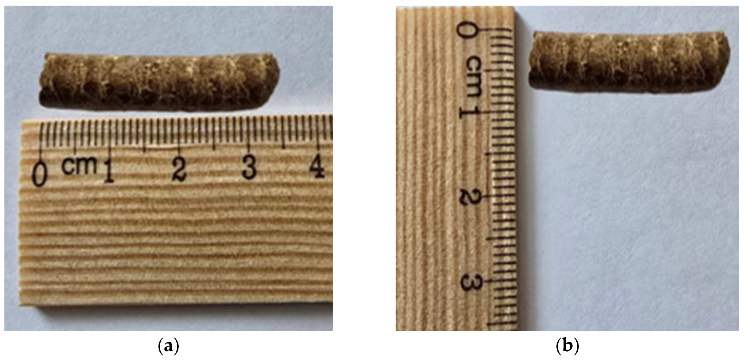
The raw materials used during combustion are shown in
Figure 1. The pellets, produced for experimental purposes, measured 3.5 ± 1 cm in length and 6 ± 1 mm in diameter. The selected blend ratio of 70% wood to 30% sunflower husks was based on preliminary tests, as this offers a favorable balance between calorific value and ash content. However, it should be noted that future investigations will focus on testing various wood-to-sunflower husk proportions to further optimize combustion performance and emissions.
In Bulgaria, biomass pellets, primarily derived from wood and agricultural waste, are in the process of market research and establishment. Wood pellets are preferred due to their high energy value, low ash content, and good compatibility with existing heating systems, despite their higher price. On the other hand, pellets made from agricultural biomass, including sunflower husks, are more affordable but are often overlooked due to their lower calorific value and higher ash content, which increases maintenance requirements and requires specialized equipment. Mixed pellets, created from a combination of sunflower husks and coniferous wood residues, offer a balanced solution. The coniferous wood improves the combustion characteristics and calorific value of the pellets, while the addition of sunflower husks reduces production costs while utilizing agricultural waste that would otherwise remain unused. Enhancing the composition and technological process can reduce ash content and increase combustion efficiency, making these pellets more attractive for residential heating systems.
Marketing research was conducted through a short consumer survey, and the obtained market feedback is essential for the successful introduction of mixed pellets. The survey was carried out in retail stores selling pellets. In total, 153 pellet users were surveyed between September 2024 and February 2025. The questions asked were structured in pairs and are as follows:
What is the most important factor for you when choosing pellets?
Is there a reason you would choose mixed pellets over wood pellets?
If manufacturers improve the quality of mixed pellets (calorific value and ash content), would you switch to them?
Would you pay a lower price for mixed pellets if they offered higher calorific value and lower ash content?
Do you believe that mixed pellets have the potential to become a preferred heating source in the future?
What would be the decisive factor for you when switching to mixed pellets?
A deep understanding of customer expectations and requirements is essential for guiding production optimization, ultimately supporting the development of more cost-effective and efficient products. Furthermore, the integration of innovative solutions into the manufacturing process is expected to improve product quality and significantly improve the competitiveness of these fuels within the domestic market.
2.2. Experimental Setup
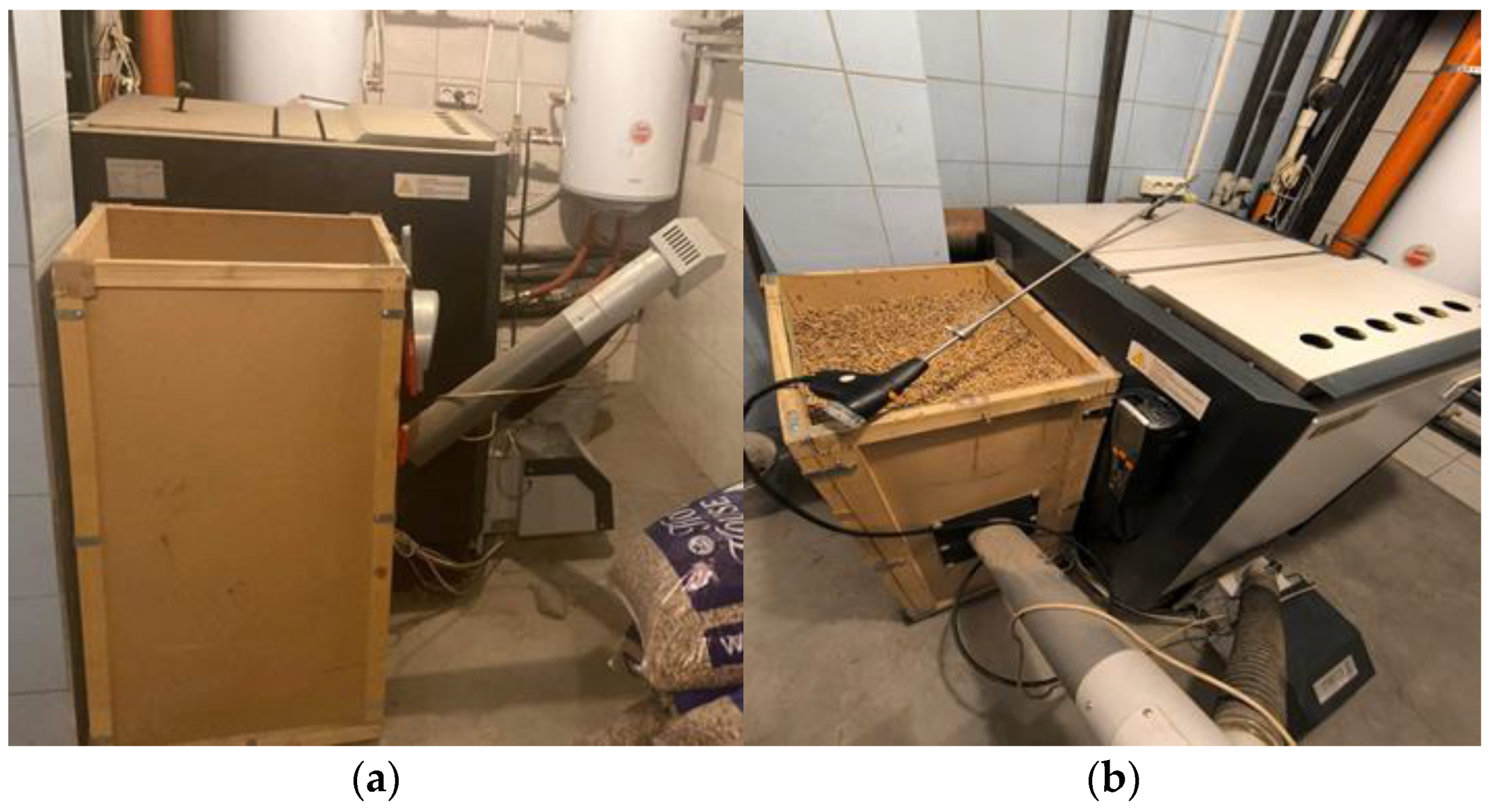
The experimental combustion of the pellets is conducted in a household pellet boiler, which is part of an operational installation (
Figure 2). The boiler is equipped with a dedicated pellet burner and a storage bunker. The composition of the flue gases is determined using a “TESTO 340” gas analyzer, Global test Ltd., Sofia, Bulgaria.
The burner is designed for burning various types of pellets and is equipped with an automated fuel feeding system from the bunker. This technology allows for better temperature control and management of the combustion process, ensuring a high efficiency and minimal ash production. The pellet burner has a nominal power of 35 kW, with an operating range between 10 and 35 kW.
The gas analyzer operates in accordance with the manufacturer’s specifications. The device can measure different gas components with a high accuracy across a wide range. The oxygen (O2) concentration is measured from 0 to 25 vol% with an accuracy of ±0.2 vol%. Carbon monoxide (CO) is measured in the range of 0–10,000 ppm, with a varying accuracy depending on the concentration, as follows: ±10 ppm or ±10% of the measured value up to 200 ppm, ±20 ppm or ±5% in the range of 201–2000 ppm, and ±10% for concentrations between 2001 and 10,000 ppm. For low CO concentrations (CO low) in the range of 0–500 ppm, the accuracy is ±2 ppm for values up to 39.9 ppm and ±5% for the rest of the range, taking into account an additional temperature coefficient of 0.25% of the Kelvin reading. Nitric oxide (NO) is measured in the range of 0–4000 ppm with an accuracy of ±5 ppm up to 99 ppm, ±5% of the measured value between 100 and 1999 ppm, and ±10% for values from 2000 to 4000 ppm. For low concentrations of NO (NO low) in the range of 0–300 ppm, the accuracy is ±2 ppm up to 39.9 ppm and ±5% for the remaining values. Nitrogen dioxide (NO2) is measured in the range of 0–500 ppm, with an accuracy of ±10 ppm up to 199 ppm and ±5% for concentrations from 200 to 500 ppm. Sulfur dioxide (SO2) is measured in the range of 0–5000 ppm, with an accuracy of ±10 ppm up to 99 ppm and ±10% of the measured value for higher concentrations.
2.3. Modeling of the Combustion Process
2.3.1. Modeling of the Geometry
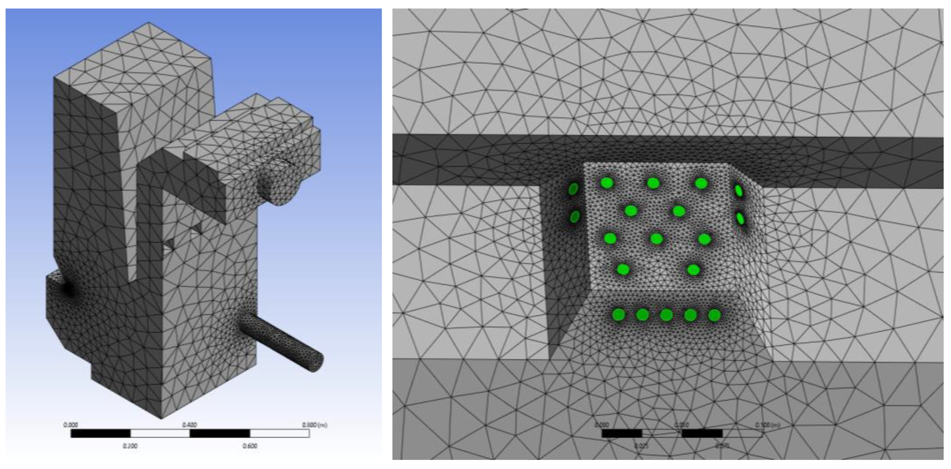
The combustion process model is developed based on the average values of the measured parameters. The three-dimensional model of the boiler’s combustion chamber (fuel and air inlets, as well as the flue gas outlet) is designed according to the actual structural parameters and is shown in
Figure 3.
The created computational mesh includes 602,674 elements and 109,329 nodes, with element sizes ranging from 0.0007 m to 0.07 m. To enhance accuracy, the mesh has a higher density in the areas of primary air supply, pellet combustion, secondary air inlet, and flue gas duct. The useful heat load is modeled as a negative heat flux on the heat exchange surfaces of the boiler. One of the areas with a finer mesh is shown in
Figure 3.
The application of finer computational meshes and the reduction in time steps contribute to more precise results regarding the distribution of flue gases and heat transfer in the boiler combustion chamber.
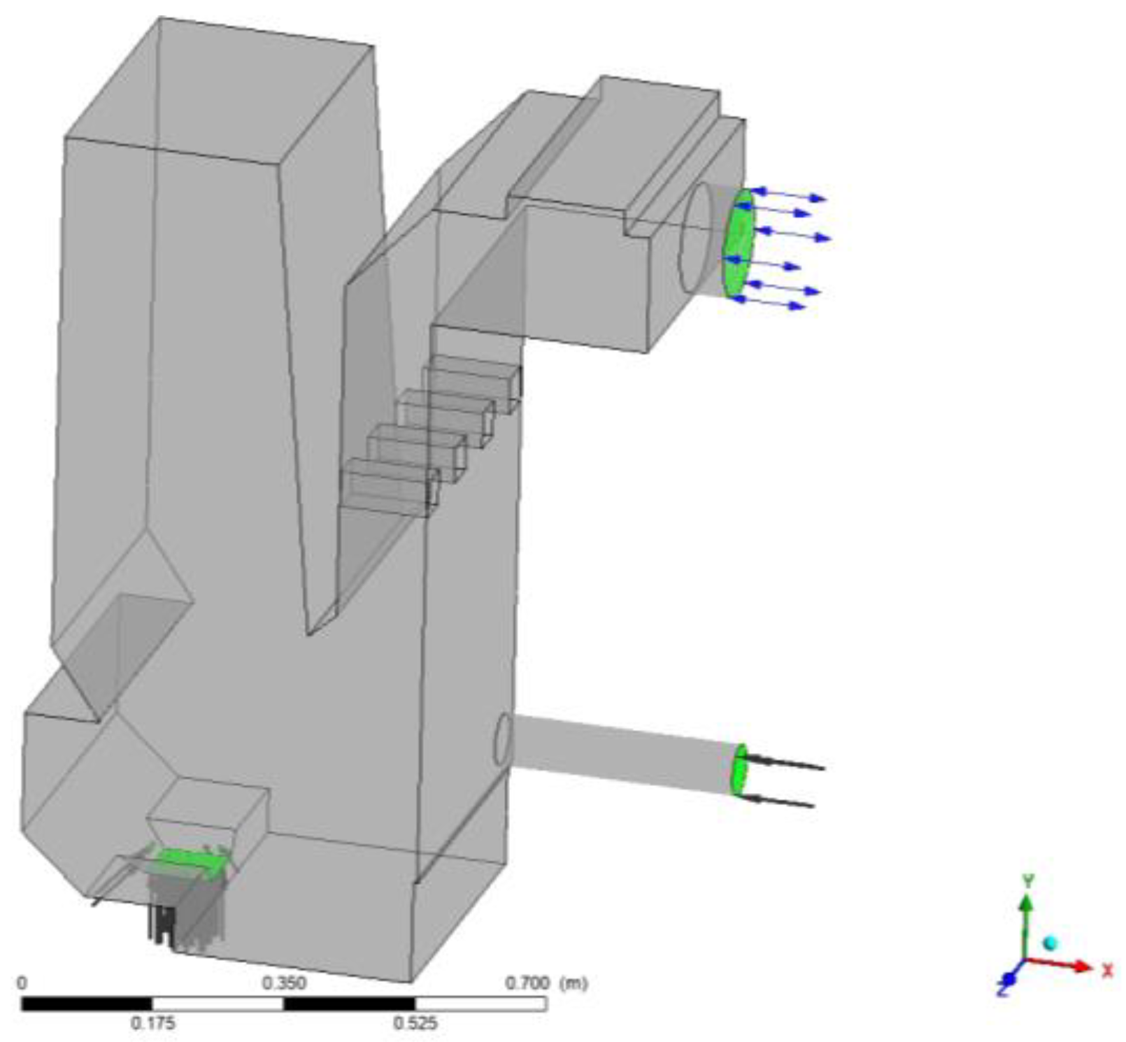
2.3.2. Definition of Boundary Conditions
The boundary conditions include defining the heat transfer characteristics of the walls and the dynamics of the fluid flows (
Figure 4). Modern computational methods are used to simulate combustion processes. The main approaches include Direct Numerical Simulation (DNS), Large Eddy Simulation (LES), and Reynolds-Averaged Navier–Stokes (RANS). DNS offers a high accuracy but requires significant computational resources and is not suitable for large-scale simulations. LES allows for modeling larger vortex structures in the combustion process, making this approach applicable to complex systems with high turbulence. RANS is a widely used method for modeling combustion processes, as it provides an effective balance between accuracy and computational efficiency.
For modeling the combustion of solid fuels, the principle of equivalent gaseous combustion is used, where the solid fuel, through conversion, is considered as gaseous combustion components, including methane, carbon monoxide, and water vapor. This approach allows for the use of developed models for gaseous fuel combustion, which account for heat exchange through convection and radiation, the mass flows of flue gases, heat transfer, and the concentrations of key emissions such as CO, CO2, and NOx.
The applied method is based on the pyrolysis approach implemented in the Fire Dynamic Simulator (FDS). In this model, the mass flow of a pre-defined gaseous hydrocarbon fuel is calculated, which is then applied in the “combustion zone” with a known heat release rate from the burning solid material.
The method allows for the simulation of the combustion process of solid fuels using RANS-based software products, such as ANSYS CFX ver. 2021 R1. Available gas-phase combustion models are used for calculations to analyze the mixing and chemical reactions that occur. Heat transfer through radiation during the combustion of solid fuels can be modeled by adjusting the radiation model to ensure an equivalent emission characteristic of the flame for different types of fuels.
The turbulence of the combustion process is represented by the turbulent kinematic viscosity, turbulent kinetic energy, and energy dissipation rate, which are stepwise calculated using appropriate turbulence models.
Heat transfer through the enclosing structure is modeled using the ambient temperature and the heat transfer coefficient of the corresponding surface. The inner surface is assumed to be adiabatic; furthermore, for more accurate modeling of the processes, the included heat exchangers are represented as walls with a negative heat flux, but they are not a subject of this study.
The boundary conditions are summarized in
Table 1.
2.3.3. Mathematical Modeling
The system of partial differential Equations (1)–(10) is solved based on discretization using a finite volume mesh (FVM). The continuity equation for the
k-th component is as follows:
where
—density of the
k-th component,
; —velocity of the
k-th phase,
; —a partial derivative of density with respect to time, describing the change in the density of the
k-th component over time, and
;
—mass addition or removal for the
k-th component,
.
The equation of state for the
k-th component is as follows:
where
—average density of the gas mixture,
;
—average value of the pressure,
—average temperature of the gas, K;
—universal gas constant,
;
—mass fraction of the
k-th component,
—molar mass of the
k-th component,
; and
—sum of the ratios of the mass fractions to the molar masses of the components,
.
The momentum equation under non-zero gravity for modeling the buoyancy force is as follows:
where
—external forces acting on the
k-th component,
.
The energy conservation equation is as follows:
where
—internal energy of the
k-th component,
, and
—specific kinetic energy of the
k-th component,
;
The turbulence model using the standard
k-ε model is as follows:
where:
—turbulent dynamic viscosity, ;—turbulent kinetic energy, ; —turbulent energy generated by the interaction of viscous forces and fluid flow deformations, ; and —dissipation of turbulent kinetic energy, .
The “
k-ε” model in various computational environments comes with different predefined constant values, as follows:
The combustion model in the gas phase is as follows:
where
—rate of the chemical reaction of the
k-th component,
.
The radiation model is as follows:
where
describes the radiation emissions from the material as a function of its temperature.
The mass flow rate and mass fractions of the components of the converted fuel are calculated using the following equations:
where
—heat flux obtained from the combustion of solid and gaseous fuel, kW/m
2;
—mass flow rate of solid fuel, kg s
−1;
—lower heating value of solid fuel, kJ kg
−1;
—volumetric flow rate of gaseous fuel under normal physical conditions, m
3 s
−1;
—lower heating value of gaseous fuel, kJ m
−3;
—volumetric flow rates of the components of the flue gases under normal physical conditions, m
3 s
−1;
—specific volumes of the flue gases during the combustion of solid fuel under normal physical conditions, m
3 kg
−1; and
—specific volumes of the flue gases during the combustion of gaseous fuel under normal physical conditions, m
3 m
−3.
The necessary conversions from solid to gaseous fuel, based on the known composition of the material, are presented in
Table 2. The unknown variables (CH
4, CO, H
2S, H
2O, and
) are obtained through Equations (16) and (17).
2.4. Numerical Simulation of the Combustion Process
The numerical simulation of the combustion process of pellets in a household hot water boiler is implemented based on the assumptions presented above for the adopted mathematical framework and the corresponding boundary conditions. The pellets are burned using an appropriate pellet burner, in accordance with the recommendations of the boiler manufacturer. For the purpose of the study, two methods of primary and secondary air supply are simulated, with ratios of 40/60 and 60/40.
The concentration of SO2 generated during combustion is negligible, and, therefore, its impact on the overall process can be disregarded. The concentration of H2S is assumed to be zero, and its volumetric flow rate is added to when calculating the gas composition. This simplifies the simulation and allows for the use of a two-step combustion model “Methane-Air WD2 NO PDF”, integrated into the CFX software. The model includes all the main gas components characteristic of the combustion process in the boiler. Also, it allows for the analysis of nitrogen oxide (NOx) formation under appropriate conditions.
The k-ε model is used to close the system of equations and model the turbulent nature of the flows. The difference in gas temperatures leads to the emergence of a lifting force, which is modeled by taking into account the variations in density between the local gas flow and the reference value of the surrounding air. The heat transfer via radiation is simulated using the P1-approximation, taking into account the radiative properties of the gas mixture in the combustion chamber.
3. Results
3.1. Experimental Studies of the Flue Gas Parameters
A total of 15 separate measurements of flue gases were conducted. In order to guarantee accurate results, a waiting period was provided between measurements for the stabilization of the combustion process. As part of the experiment, additional adjustments were made to the fan to control the supply of primary and secondary air.
Table 3 presents the average results from the measurements, which were used to develop the model.
3.2. Results from the Numerical Solution
The models are solved numerically under the conditions described above for the mixed pellets and air supply methods and are validated through mass and energy balances based on the obtained results. Since the difference between the incoming and outgoing flows is below 5%, the results can be considered as reliable for the evaluation of the processes in the modeling. The combustion process is presented in
Table 4 and the boundary conditions are defined in
Table 5.
3.3. Model Studies
The model studies present the results of the numerical modeling of the combustion process. The simulations analyze the distribution of temperature, airflows, flue gases, and pressure.
The temperature distribution in the combustion chamber during the burning of mixed pellets is shown in
Figure 5. The main combustion reaction occurs in the area around the burner, where higher temperatures are concentrated.
The distribution of the temperature field demonstrates the formation of a hot zone (where the fuel decomposes and releases heat) and low temperatures in the area of secondary air supply (confirming that its presence is intended for cooling). The difference between the two temperature fields is that when air is supplied in a 40/60 ratio, combustion is more intense in one zone, while with a 60/40 ratio, a more even distribution of temperatures is observed.
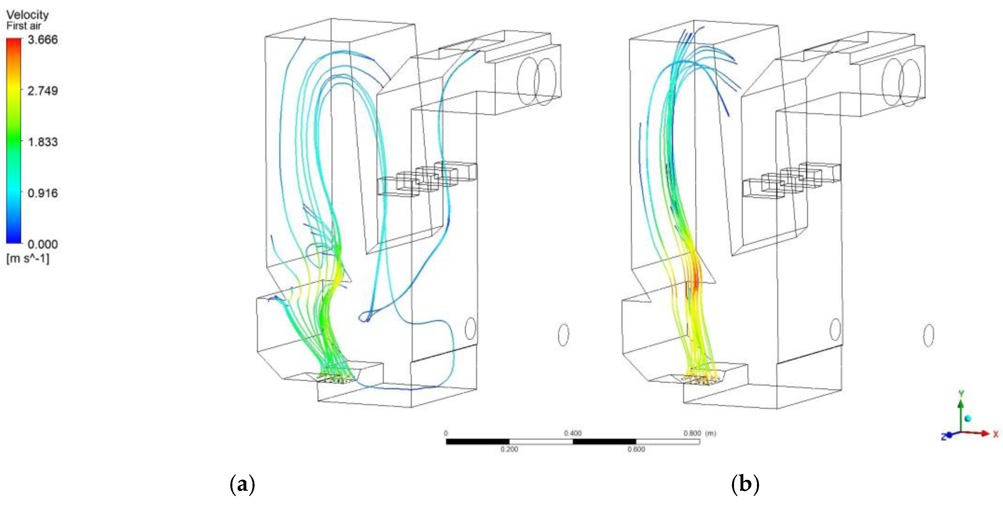
The movement of the primary air in the chamber is shown in
Figure 6. The primary air assists in igniting the fuel and maintaining the combustion process.
At an air supply ratio of 40/60, the flow lines form an air stream that directly enters the combustion zone, while at a 60/40 ratio, the primary air mixes with the flue gases, which can reduce the intensity of the combustion process.
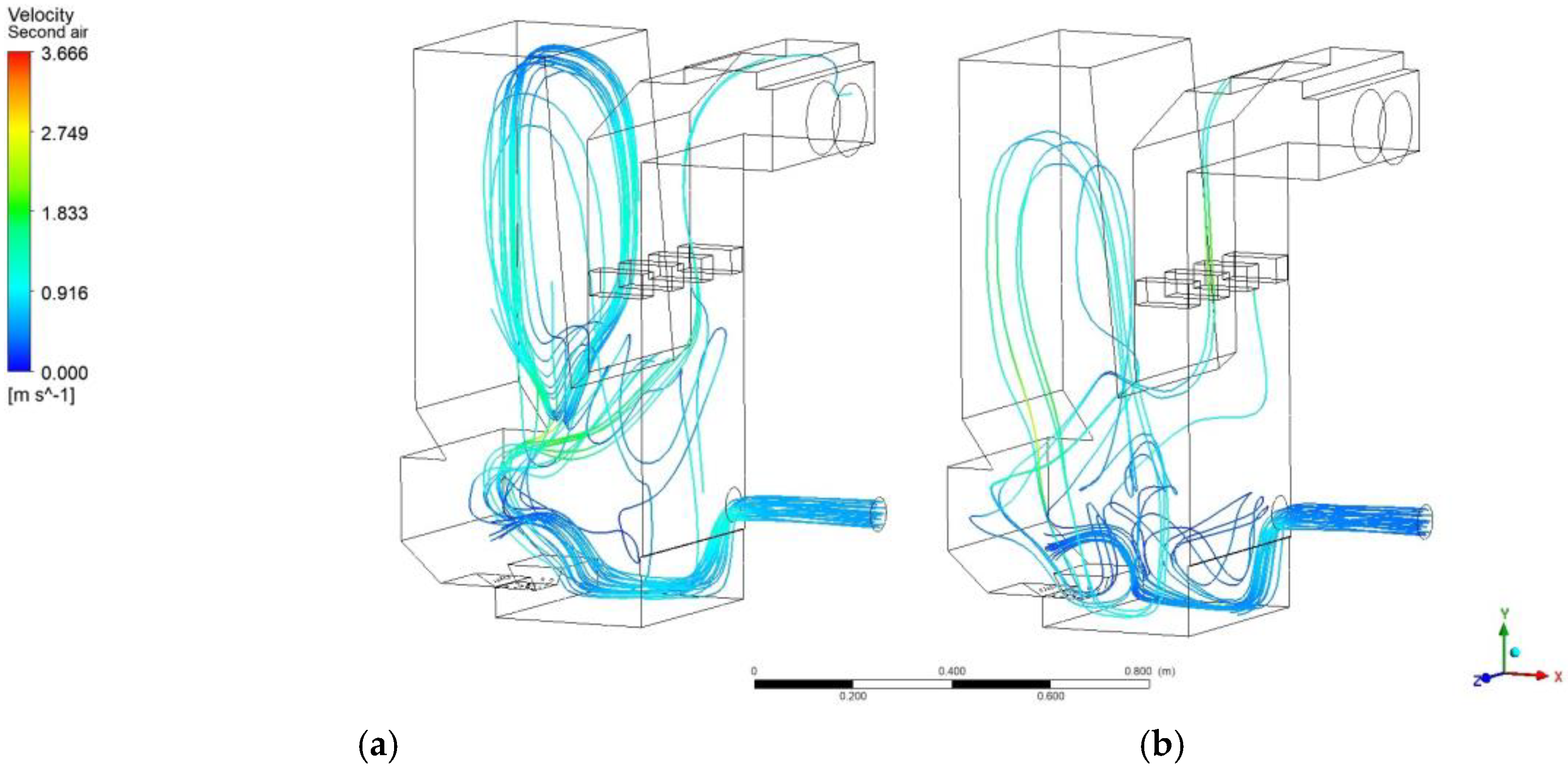
The distribution of the secondary air flow is shown in
Figure 7. Secondary air helps with the afterburning of the flue gases and is a key factor in the more complete combustion of the fuel.
When the air supply ratio is 40/60, part of the air does not fully mix with the flue gases, which could lead to higher CO emissions and incomplete combustion. At the 60/40 air supply ratio, the secondary air has the opportunity to penetrate deeper into the combustion chamber, aiding complete combustion and reducing harmful gas emissions.
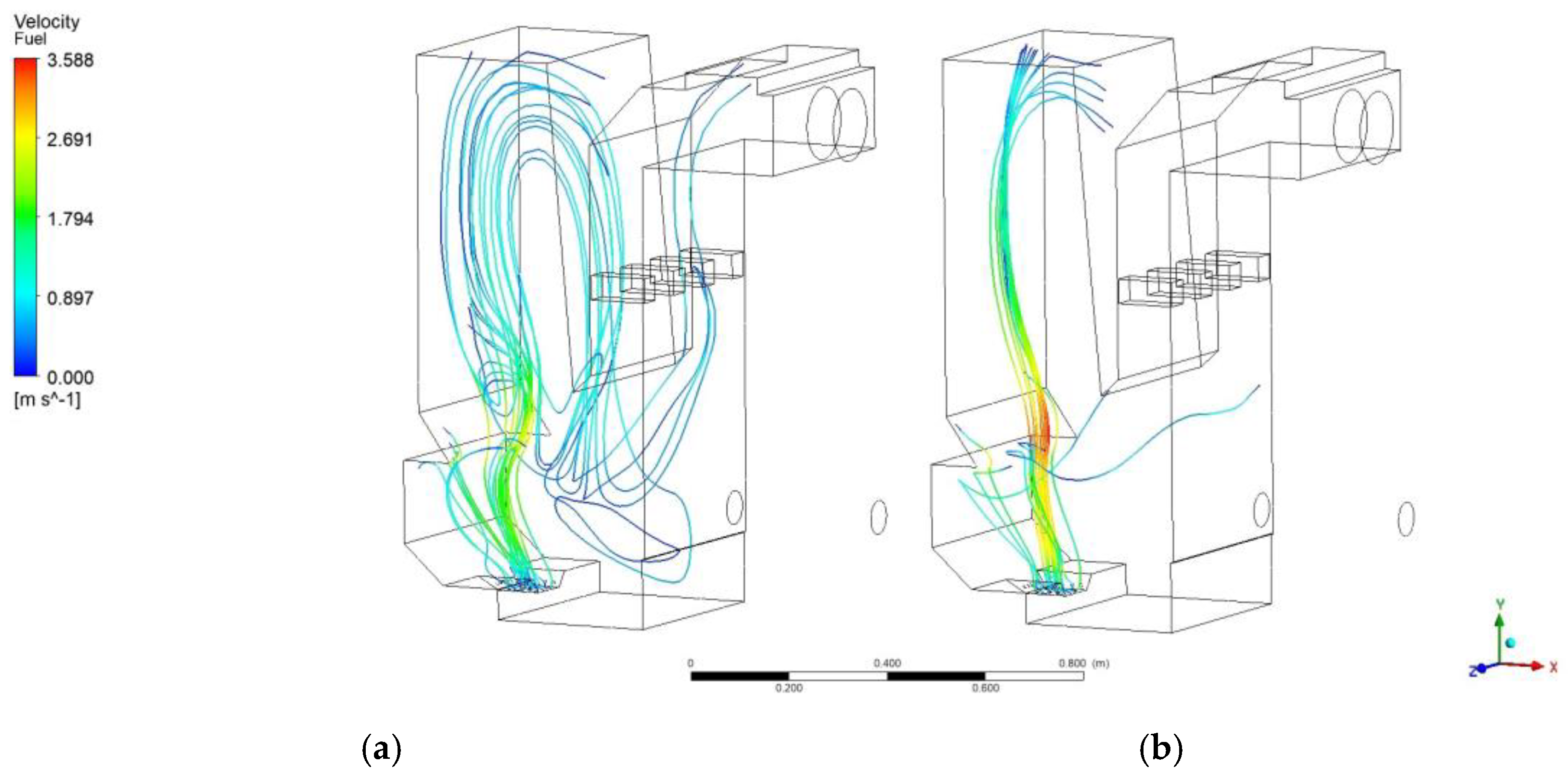
The flow lines of the flue gas movement are shown in
Figure 8. They track the movement of the flue gases in the combustion chamber and their exit through the chimney.
At an air supply ratio of 40/60, the flue gases swirl around the burner. This can result in uncontrollable temperature peaks and a more uneven heat distribution. With a 60/40 air supply ratio, the flue gases are distributed more evenly throughout the chamber, ensuring better circulation and more efficient heat transfer to the heat exchange surfaces of the boiler.
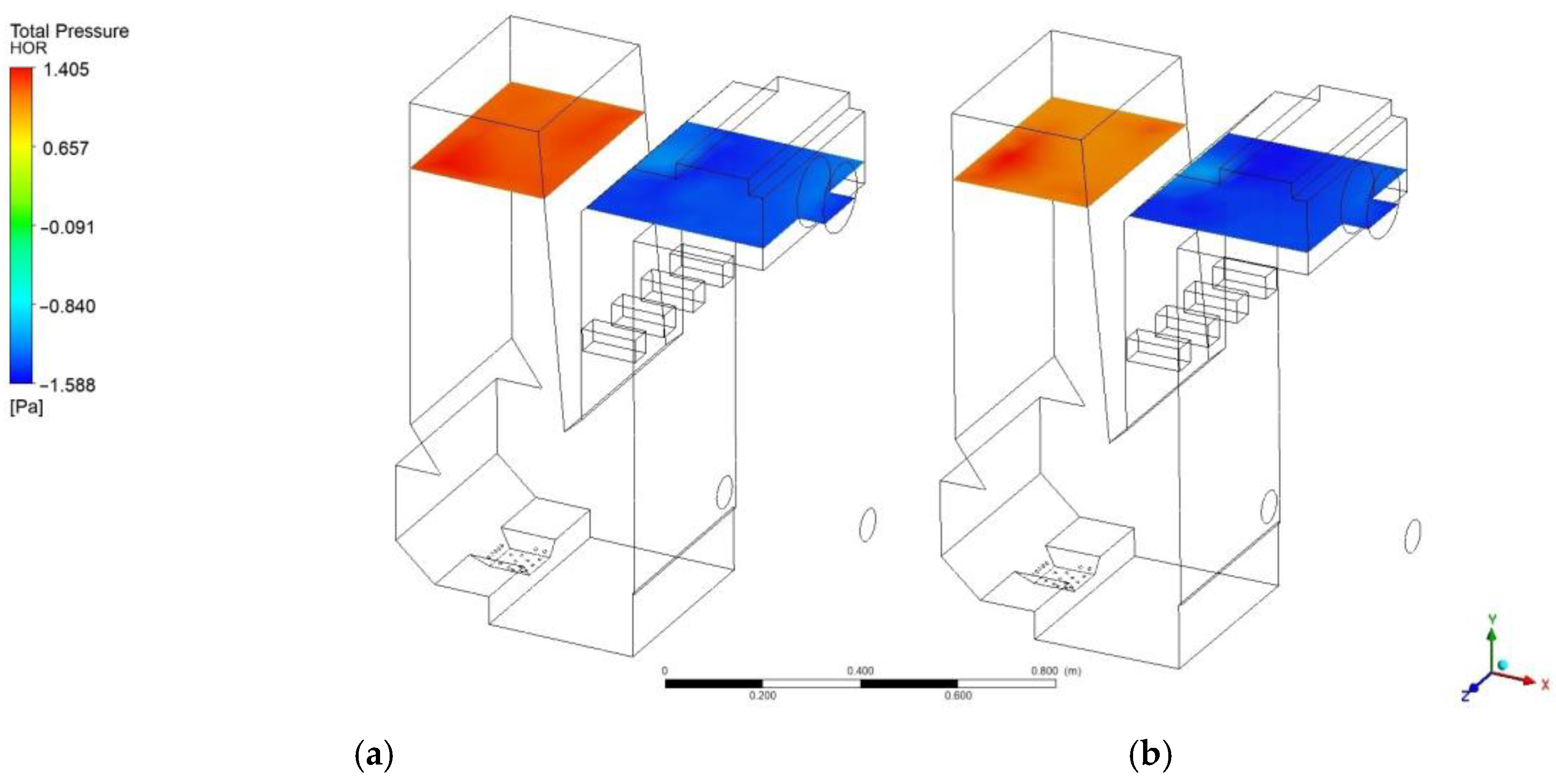
The pressure distribution in the gas chamber is presented in
Figure 9. Pressure is a parameter that influences the rate of the combustion process, the mixing of gases, and the overall efficiency of the combustion process.
At an air supply ratio of 40/60, a higher pressure is observed in the lower part of the chamber where the primary air enters, creating an intense air flow. At a 60/40 ratio, the pressure is more evenly distributed, which could lead to a better combustion stability and fewer turbulent disturbances.
A summary of the obtained results and their comparative analysis is presented in
Table 6, confirming the high reliability and applicability of the models used for the preliminary assessment of the operational parameters of the combustion process.
3.4. Results of the Marketing Research
The results of the marketing research on consumer preferences are presented in
Figure 10,
Figure 11 and
Figure 12.
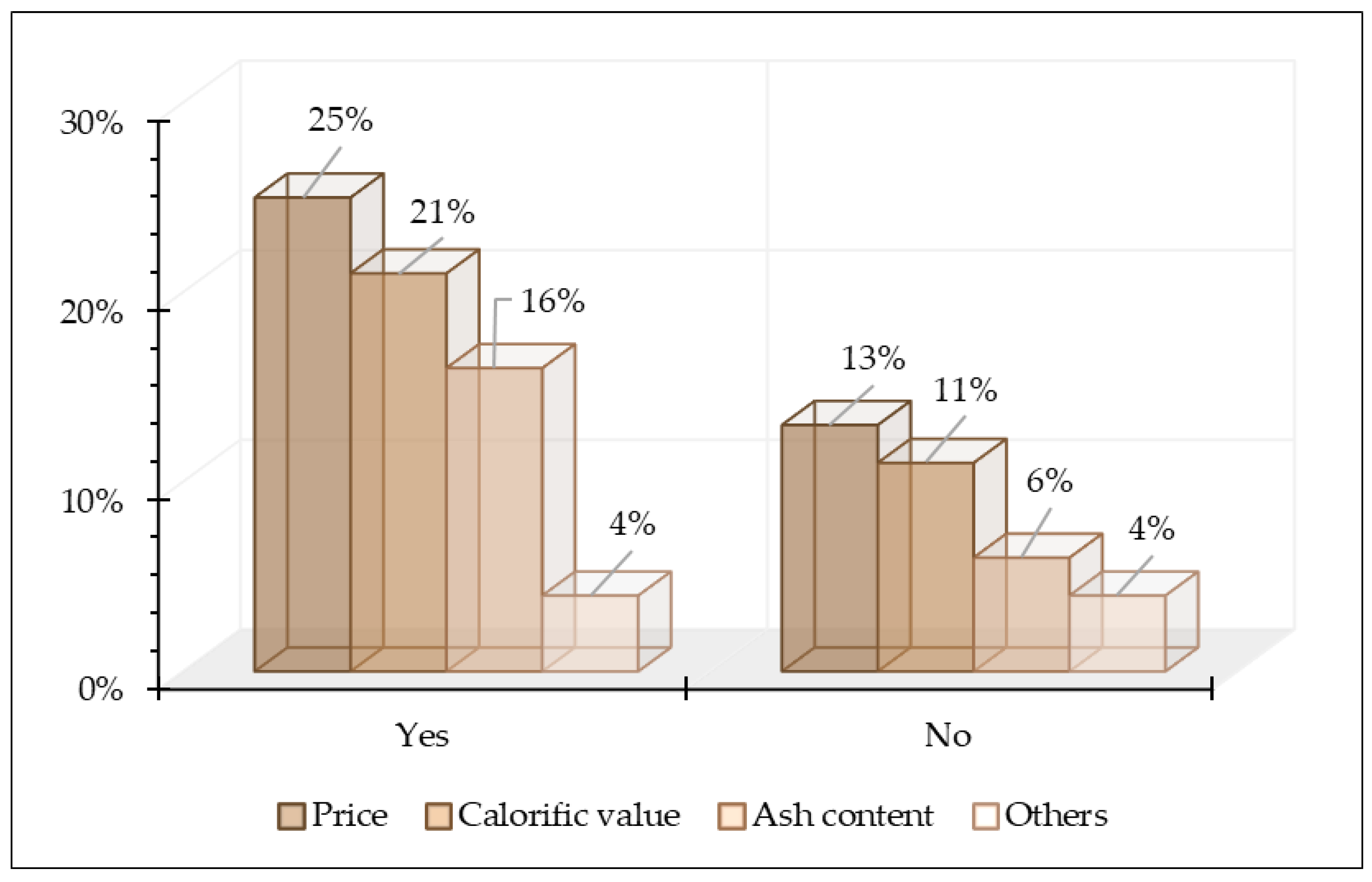
Figure 10 reveals distinct trends in consumer decision making when selecting pellets. Notably, 25% of the respondents identify price as the most important factor, emphasizing that cost remains a dominant consideration in their purchasing decisions. However, 13% of the respondents indicate that price is not a decisive factor for them, suggesting that some consumers value additional benefits beyond a lower price. Furthermore, 21% of the respondents consider the calorific value to be a crucial criterion, reflecting a strong interest in a higher efficiency and superior heating performance. In contrast, 11% do not deem calorific value as being essential, implying that some consumers are willing to compromise on this aspect if the product offers other advantages, such as a lower cost or easier maintenance. Ash content is a significant factor for 16% of the respondents, highlighting a demand for cleaner combustion and reduced residue. Conversely, 6% do not regard it as a key factor, suggesting that, for some consumers, the emphasis is on other attributes. The least concern is seen in the “Other” category, with only 4% selecting this option. This indicates that the primary criteria for selecting pellets are well-established and consumers are rarely influenced by additional, less common factors.
These insights provide a clear understanding of the key drivers behind consumer choices, which can be leveraged to refine product offerings and marketing strategies, ensuring alignment with consumer priorities and enhancing competitiveness in the market.
The results in
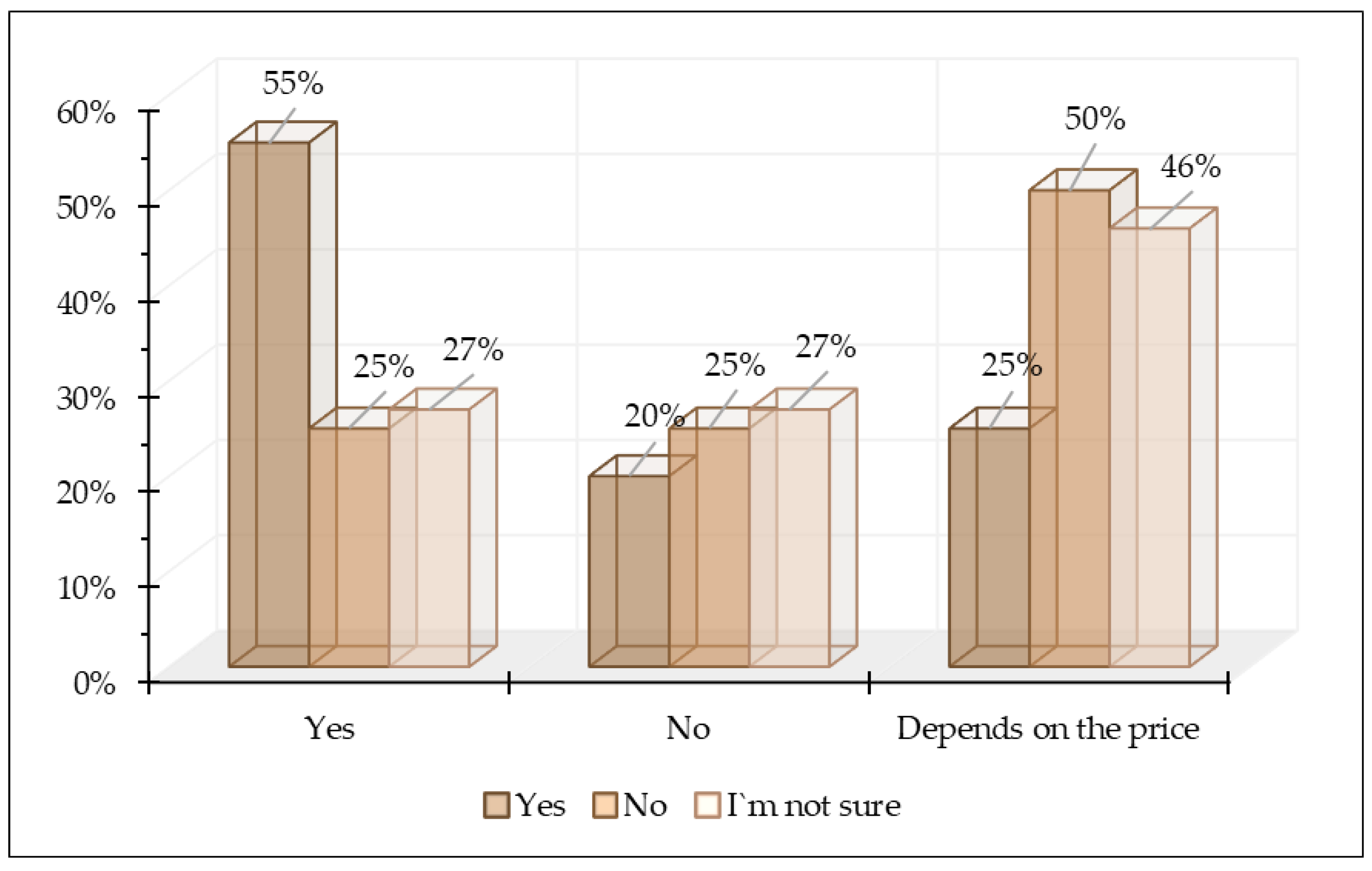
Figure 11 provide valuable insights into consumer attitudes toward mixed pellets and the potential impact of quality improvements. A significant 55% of the respondents express a willingness to switch to mixed pellets if manufacturers enhance their calorific value and reduce their ash content, indicating a strong demand for higher-quality products. At the same time, 20% firmly state that they would not switch to mixed pellets even with quality improvements, pointing to either brand loyalty or a lack of trust in new product offers. In total, 25% of the respondents emphasize that their purchasing decision would hinge on price, reinforcing the continued importance of cost in consumer choices. When asked if they would pay a higher price for mixed pellets with a higher calorific value and lower ash content, 55% of the respondents again state that they would accept such an increase if the quality justifies it. This underscores the following key finding: many consumers are not solely motivated by price, but are also looking for enhanced efficiency and performance. On the other hand, 25% of the respondents would not pay more, reaffirming that price remains the dominant factor for this group, even when quality is improved. An intriguing 27% of the respondents are uncertain, suggesting that while they acknowledge potential improvements, they remain unsure if the benefits would outweigh the cost increase.
These findings clearly segment the market into the following three distinct consumer groups: those willing to pay a premium for better quality, those who prioritize price above all else, and those who seek an optimal balance between price and quality. To successfully capture the market, manufacturers must focus on improving the quality of mixed pellets while also ensuring competitive pricing. A strategic approach that highlights the value proposition—an improved performance, efficiency, and cost-effectiveness—will be essential to attract a broader consumer base and differentiate such products in the competitive Bulgarian market.
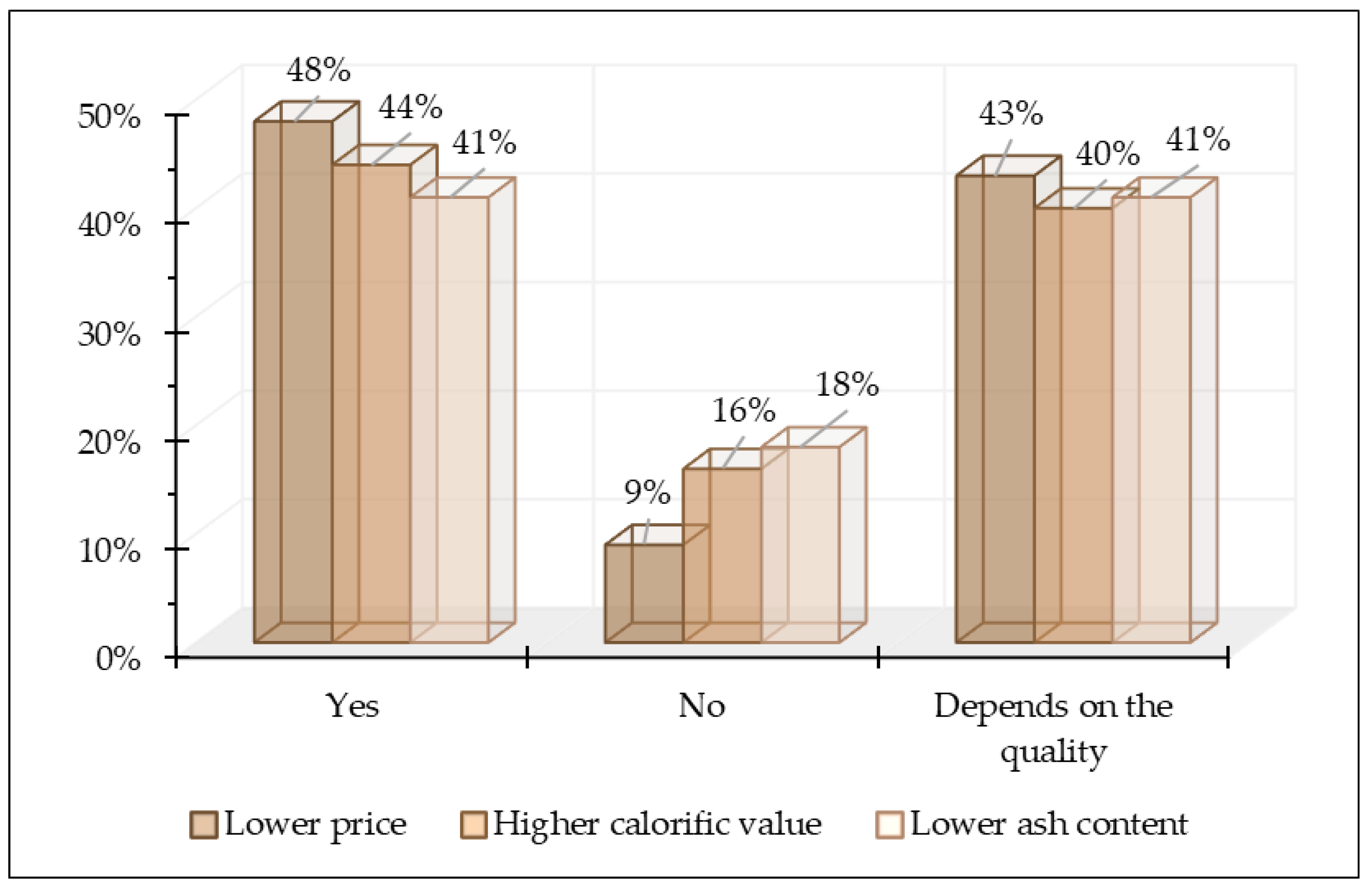
Figure 12 presents results that reveal significant interest in mixed pellets, while also highlighting certain conditions that could influence the decision to switch to them. When asked whether mixed pellets have the potential to become their preferred heating source in the future, 48% of the respondents answer positively, which indicates that nearly half of the consumers see them as a sustainable alternative to wood pellets.
At the same time, 43% of the respondents state that their decision would depend on the product quality, indicating that expectations for a better calorific value, lower ash content, and easier maintenance will be key factors in perceiving mixed pellets as a reliable heating source. Only 9% categorically reject this option, suggesting a relatively low level of skepticism about the potential of mixed pellets. Regarding the factors that would be decisive in switching to mixed pellets, 48% of the respondents cite lower prices as the main motivator. This confirms that the price factor remains the leading consideration when choosing heating materials. Meanwhile, 44% highlight higher calorific value as an important factor, demonstrating that consumers are looking for not only affordability, but also greater combustion efficiency. In total, 41% of the respondents emphasize the importance of lower ash content, which underscores the demand for easier maintenance and cleaner burning. The results suggest that mixed pellets have the potential to succeed in the market, but their success will depend on the balance between price and quality. A high calorific value and low ash content are desired by consumers, but price remains the decisive factor in this choice. This implies that manufacturers will need to find ways to offer mixed pellets with competitive pricing and improved characteristics to meet the expectations of various consumer groups.
4. Discussion
The complete combustion of pellets in domestic boilers is essential for achieving a higher energy efficiency and reducing harmful environmental impacts, as highlighted by the authors in [
47], who emphasize that resource optimization is a core concept in the circular economy. The foundation of this study demonstrates the importance of quality combustion for the efficiency of the combustion process. Investigating the processes in the combustion chamber allows for the refinement of the combustion mechanism through an in-depth analysis of the interactions between turbulent flows, heat and mass transfer, and the chemical reactions occurring, as noted in [
48,
49]. Modern software platforms, such as Ansys CFX ver. 2021 R1, provide the ability to precisely model and simulate combustion processes, which aligns with the conclusions of the authors in [
49], who highlight the key role of digitalization in improving combustion efficiency.
The mixed pellets are effective for combustion in the selected boiler, as they provide a balanced environmental and energy performance. According to a study [
50], combining different biomass sources can reduce carbon emissions and improve overall ecological footprint. The low levels of CO and CH
4 in the flue gas are indicators of complete combustion and align with the conclusions in [
51], which emphasize that optimizing combustion processes reduces harmful emissions. The k-ε turbulence model used to analyze the movement of gas flows provides verified data that minimize the discrepancy between numerical predictions and real measurements. According to research in [
52], the accuracy of models is crucial for their practical application, while also meeting the requirements for high temperatures that necessitate the use of new, high-tech materials for burners and boiler walls. The proposed approach for modeling combustion processes offers new opportunities for optimizing various pellet combustion systems. As noted in [
53], the reliability of these methods is crucial for the advancement of energy technologies and serves as a foundation for innovations in the industrial sector.
The marketing research reveals that, despite the high interest in mixed pellets, consumers remain divided when it comes to the key factors influencing their purchasing decisions. Although 48% of respondents would switch to mixed pellets at a lower price, a large share of them are also looking for better quality characteristics—44% prioritize calorific value and 41% seek pellets with a lower ash content. This balance between price and quality presents a challenge for manufacturers, who must meet consumer expectations for both affordability and performance. To succeed in this competitive market, manufacturers will need to provide a product that balances cost-effectiveness with improved efficiency, without compromising on quality [
54,
55]. The fact that 43% of the respondents would consider switching to mixed pellets only if the product quality is improved suggests that consumer trust in new alternatives remains cautious. This emphasizes the importance of building strong consumer confidence through clear communication, robust evidence, and proof of product effectiveness. The success of mixed pellets in the market will depend on manufacturers’ ability to educate consumers and demonstrate the tangible benefits of these innovations [
56].
5. Conclusions
The study investigates the combustion of mixed pellets made of wood and sunflower husks, combining experimental measurements and numerical modeling. The results show that a 60/40 ratio between primary and secondary air ensures stable combustion, reduces CO and NOx emissions, and increases energy efficiency. CFD simulations confirm a high degree of agreement with the experimental data.
The combustion model demonstrates that the formation of a hot zone and the better mixing of air with the flue gases lead to complete combustion and a reduction in the generated carbon emissions. The precise adjustment of parameters improves boiler performance both in terms of efficiency and environmental impact.
The study provides information on improving the combustion process in biomass-fired boilers. The use of mixed pellets can reduce ecological impacts, particularly with the proper configuration of the combustion system. Different climatic conditions and boiler types can affect the combustion process. The present study is limited to a single boiler type and a fixed pellet mixture. The results from the models form the basis for future improvements in burners and combustion chambers.
The marketing research clearly indicates strong consumer interest in mixed pellets, with a key focus on competitive pricing and enhanced quality features such as a higher calorific value and lower ash content. To effectively capture market share, manufacturers must strategically balance cost and performance, ensuring that the product not only meets customer expectations, but also offers compelling proof of its advantages. Success will hinge on delivering a product that combines affordability with a superior efficiency, backed by clear and convincing evidence of its benefits.


