Article

Real-Time Drilling Performance Optimization Using Automated Penetration Rate Algorithms with Vibration Control

Department of Energy and Petroleum Engineering, Faculty of Science and Technology, University of Stavanger, Postboks 8600 Forus, 4036 Stavanger, Norway
Fuels 2025, 6(2), 33; https://doi.org/10.3390/fuels6020033
Submission received: 20 February 2025 / Revised: 22 April 2025 / Accepted: 27 April 2025 / Published: 2 May 2025

Abstract

Automation has transformed process optimization across industries by enhancing efficiency, safety, and reliability while minimizing human intervention. This paper presents a model-based optimization strategy tailored for automated drilling operations, focusing on maximizing performance while maintaining operational safety. The approach employs real-time control of key parameters, such as applied force and rotational speed, through a robust closed-loop control system. An adaptive detection algorithm is incorporated to dynamically adjust operational parameters when encountering changing conditions. This real-time adaptability ensures efficient performance under diverse scenarios while mitigating risks. In the simulation, the data used for modeling drillstring dynamics are sourced from a publicly available benchmarking dataset, which provides a reliable basis for evaluation. From the simulation results, it is clear that the drilling optimization framework is capable of achieving high performance with lower energy consumption while maintaining effective vibration mitigation and prevention. This balance is essential for ensuring operational efficiency and tool longevity in dynamic environments. The findings highlight the potential of this framework to enhance automated systems in energy, construction, and other sectors requiring precise control of dynamic mechanical processes.

1. Introduction

The optimization of operational performance is a critical focus in industries that involve mechanical systems and dynamic environments. Achieving high efficiency in penetration processes, such as drilling or excavation, requires the careful adjustment of operational parameters, including applied force, load distribution, rotational speed, flow rates, and material properties of tools and working fluids. Effective optimization not only improves penetration rates (ROPs) but also ensures system stability, enhances material removal efficiency, minimizes vibrations, and maintains precise control over operations. The real-time detection of environmental or material changes is vital for adaptive optimization. By dynamically adjusting parameters to accommodate varying conditions, it ensures consistent performance, extending its relevance beyond traditional drilling to applications such as mining, construction, and energy systems.

1.1. ROP Modeling

ROP modeling is a crucial area in drilling operations, with numerous studies focused on improving its accuracy through various modeling and analytical techniques. Historically, ROP modeling relied heavily on physical or empirical models, utilizing fundamental engineering principles or historical data, respectively. These models correlate drilling parameters such as the weight of the bit, the rotary speed, and the fluid properties with the penetration rate, as described by [1]. For example, ref. [2] presented models that correlate drilling parameters, such as bit speed and applied force, with rock properties, offering a mechanical perspective on ROP enhancement. More recently, ref. [3] introduced a physics-based ROP model that incorporates the interaction between the bit and rock, taking into account bit wear and varying rock strength. Similarly, ref. [4] developed an integrated model that combines rock mechanics and drilling dynamics to predict the ROP more accurately under different drilling conditions.
With the advent of more sophisticated technologies, the focus has shifted toward data-driven approaches in ROP modeling; see [5,6,7,8,9,10,11]. These models utilize machine learning algorithms to predict the ROP based on extensive datasets comprising various drilling parameters. For example, ref. [12] demonstrated the application of neural networks in accurately predicting the ROP by learning from past drilling data, indicating a major shift toward more adaptive and responsive modeling techniques. Recent advances, as demonstrated by [13], who used artificial neural networks to predict the ROP based on real-time drilling data, achieved significant improvements over traditional models. Similarly, Support Vector Machines and Random Forests have been explored for their predictive capabilities in complex geological conditions [14]. More recent studies, such as those by [15,16], have further advanced data-driven ROP modeling by integrating deep learning techniques, which provide even more accurate predictions and adapt better to real-time data variations. Hybrid models that combine physical and data-driven approaches are emerging, integrating domain knowledge with machine learning to enhance prediction robustness. These models not only improve the accuracy of ROP predictions but also adapt dynamically to changing drilling conditions, providing a more reliable tool to optimize drilling operations in real time [17,18,19].

1.2. ROP Optimization

For ROP optimization, algorithms identify the most effective drilling parameters to maximize the ROP under given constraints. Techniques such as genetic algorithms, particle swarm optimization, and simulated annealing have been widely applied due to their robustness in solving nonlinear, complex problems. Foundational work by [20] introduced empirical models for ROP optimization, while ref. [21] utilized a response surface methodology to optimize drilling parameters, offering valuable insights into early developments in the field. More recent studies, such as [22], demonstrated the application of particle swarm optimization to dynamically adjust drilling parameters, resulting in significant improvements in the ROP. These studies collectively highlight the strong potential of optimization algorithms to drastically enhance operational efficiency.
Recent advancements include the work by [23], who applied genetic algorithms to optimize drilling parameters, demonstrating improved accuracy and efficiency in ROP predictions. Moreover, ref. [24] utilized an intelligent optimization algorithm and machine learning technique to adjust drilling parameters in real time, achieving more stable and efficient drilling performance. Ref. [25] explored the application of multi-objective optimization algorithms to balance the ROP with other operational constraints, highlighting the importance of a holistic approach to drilling optimization. Additionally, ref. [26] presented a comprehensive and practical approach to ROP optimization by evaluating multiple models and algorithms, demonstrating the effectiveness of the lightweight optimization techniques across both onshore and offshore datasets. Ref. [27] employed reinforcement learning techniques for real-time ROP optimization, demonstrating the potential of adaptive algorithms to improve drilling outcomes under dynamic conditions.

1.3. Research Objectives

The primary objective of this study is to develop a novel, real-time simulation framework for an advanced automated ROP control algorithm aimed at enhancing the precision, safety, and efficiency of drilling operations in the oil and gas industry. Unlike existing methods, which often focus solely on maximizing the ROP or rely on static assumptions, our approach introduces a formation-based ROP optimization model that incorporates vibration control and mitigation directly into the optimization process. This ensures that optimal drilling performance is achieved within safe operational boundaries, thereby reducing the likelihood of complications such as stick–slip, axial vibrations, and other operational inefficiencies. The key innovations of this study include the following:
  • The continuous, real-time optimization of drilling parameters based on formation characteristics integrated with vibration monitoring and control to maintain safe and efficient operations.
  • The implementation of a lightweight formation change detection algorithm enabling timely adjustments to drilling strategies as subsurface conditions evolve, thereby supporting proactive vibration control and overall system stability.
The specific subobjectives of this research are the following:
  • To develop a simple yet effective method for detecting geological formation changes, enabling rapid recognition of downhole condition shifts for proactive drilling control.
  • To enhance the ROP optimization model with a safety-focused perspective, balancing performance improvements with minimized vibration risks to ensure operational reliability.

2. Formulation-Based Penetration Rate Model

2.1. ROP Model

2.1.1. Demo Model

The Bourgoyne–Young model [20], originally developed to detect changes in pore pressure and improve drilling calculations, can also be effectively applied to assess formation hardness. This model assumes that each variable influencing the ROP can be represented by a distinct, independent function. It incorporates eight separate and independent factors, with each capturing a specific aspect of the drilling environment:
R O P = f 1 × f 2 × f 3 × f 4 × f 5 × f 6 × f 7 × f 8 ,
where f i represents the factors associated with the weight on bit (WOB), rotary speed (RPM), flow rate, mud properties, bit hydraulics, formation characteristics, and—most importantly—the type of bit used. More specifically, the factor f 1 refers to drillability, which is defined by the parameter K. The effects of normal compaction and undercompaction on the ROP are modeled by f 2 and f 3 , respectively. The factor f 4 accounts for the impact of overbalance pressure, while f 5 and f 6 capture the influence of real-time drilling control parameters such as the WOB and RPM. Finally, f 7 and f 8 represent the effects of tooth wear and bit hydraulics, respectively.
In the context of real-time ROP optimization, factors like f 5 and f 6 are especially critical, as they correspond to controllable parameters that can be adjusted to enhance ROP. The simplified Bourgoyne–Young model can therefore be expressed as
R O P = f 1 × f 5 × f 6 .
More specifically, it is the function of the WOB and the RPM as
R O P = K W O B 4 d bit a 5 R P M 60 a 6 ,
where a 5 and a 6 are the model coefficients, and d bit denotes the bit diameter. These model coefficients should ideally be selected based on specific drilling conditions and can be derived through multiple regression analyses of historical drilling data from the region. According to the original study by [1], these coefficients generally take on lower values. Alternatively, the values of a 5 and a 6 can be estimated using a simpler method by analyzing drill-off test data. The recommended lower and upper bounds for a 5 and a 6 are reported by [1]. Specifically, when drilling extremely hard formations, the coefficients tend to be lower, with a 5 = 0.5 and a 6 = 0.4 . In contrast, for extremely soft formations, the coefficients increase to a 5 = 2.0 and a 6 = 1.0 . To improve the accuracy of ROP predictions, it is essential to adjust the values of a 5 and a 6 according to the hardness of the formation. Moreover, adapting K based on formation hardness is crucial for precise ROP modeling. Rocks with higher unconfined compressive strength (UCS) typically require lower K values, indicating greater drilling resistance and resulting in a slower ROP. Conversely, formations with lower UCS values are associated with higher K values, signifying easier drilling conditions and thus a higher ROP. This adaptability of K enables a more accurate representation of the ROP across a wide range of geological formations.

2.1.2. Discussions

It is important to acknowledge the existence of various ROP models in the scholarly literature, with each developed to address specific aspects of the drilling process. In this work, we specifically highlight a model designed to account for formation types. The selection of this model (3) serves as an illustrative example within the broader context of ROP control and optimization tools available to practitioners. For the purposes of this study, we employ a straightforward ROP model based on the formation characteristics. This model is presented as a case study to demonstrate how ROP models can be effectively integrated into drilling operations. By focusing on formation types, the model simplifies the complex dynamics of drilling while capturing one of the most influential factors in determining optimal drilling parameters.
Users are afforded the flexibility to select an ROP model that best aligns with their specific operational requirements and geological conditions, drawing from a comprehensive suite of available ROP tools. The effectiveness of a drilling operation can be significantly influenced by the selected model, depending on its accuracy and adaptability to varying formation scenarios. This flexibility underscores a fundamental principle in drilling optimization: customization in the model and tool selection are essential for achieving optimal performance.

2.2. Formation Detection

2.2.1. Mechanical Specific Energy Calculation

Real-time interpretation of drilled lithology is a pivotal step in optimizing drilling operations. Mechanical drilling parameters often serve as early indicators of changing geological conditions, enabling drillers to rapidly detect transitions between successive lithological layers. This capability is crucial for optimization, as it allows for timely adjustments to drilling parameters that align with the specific requirements of the current formation. A dedicated detection system capable of accurately classifying lithologies based on changes in downhole conditions can significantly enhance drilling performance. Such a system enables early recognition of geological variations, facilitating prompt updates to real-time drilling parameters—an essential factor for maintaining efficient and effective operations.
One key metric used for lithology classification is the mechanical specific energy (MSE), which quantifies the amount of work required to remove a unit volume of rock [28]. The equation for MSE, as described by [29], is given below:
M S E = E m ( W O B A R E A + 120 π T R P M A R E A R O P )
where E m is the mechanical efficiency of a new bit ( 35 % ); A R E A is the cross-sectional area of the bit [in2]; and T is the torque [ft/h]. In practice, the confined compressive strength (CCS) can be approximated by the minimum values of the MSE. In the study by [30], a strong correlation was demonstrated between the MSE and rock strength parameters, particularly UCS and CCS. This correlation can be expressed as
C C S = M S E m i n ,
where M S E m i n is the minimum value of the MSE. In [31], the UCS and MSE are modeled by correlating digitized lithology-based UCS values with calculated MSEs from drilling parameters such as torque and the ROP. Although the correlation is supported by several researchers, it remains a topic of ongoing work and varying interpretations within the field.

2.2.2. Discussions

In this work, the ROP algorithm is designed to compute the MSE using critical drilling parameters such as the RPM, WOB, and ROP. The calculated MSE serves as an indicator of the energy required to remove a unit volume of rock and is subsequently used to estimate the formation’s hardness. This real-time feedback enables dynamic adaptation of the drilling strategy to match the geological conditions encountered downhole. For instance, based on the estimated CCS derived from the MSE, formations can be classified into five categories: very weak (1–25 MPa), weak (25–50 MPa), moderately hard (50–100 MPa), hard (100–200 MPa), and very hard (greater than 200 MPa), following the classification proposed by [32]. This classification facilitates the timely adjustment of drilling parameters and supports real-time lithology detection and decision making.
Furthermore, the study incorporates the calculated CCS as a key element in the optimization process. The CCS not only assists in selecting appropriate parameters for the ROP model but also serves as a crucial input for evaluating drillstring vibration severity within the proposed drillstring dynamic model. This integration is vital, as it facilitates real-time adjustments of control setpoints—specifically the WOB and RPM—to correspond with changes in rock hardness, thereby ensuring optimal penetration rates and operational efficiency while maintaining minimal vibration levels.
Although there is a substantial body of research addressing formation detection and CCS estimation, this study specifically utilizes the MSE as a foundational method for both identifying formation transitions and estimating their mechanical strength. The use of the MSE in this context supports the ease of implementation and understanding while also encouraging further development and customization to enhance precision and adaptability according to specific operational requirements and research objectives.

3. Drillstring Dynamic Model

3.1. Modeling

The dynamic behavior of a drill string is a critical aspect of rotary drilling that significantly influences the efficiency and safety of drilling operations. Understanding the coupled axial–torsional dynamics is essential for predicting and mitigating issues such as stick–slip oscillations, which can lead to tool failure and increased nonproductive time. Early studies on drill string dynamics focused primarily on torsional vibrations, with stick–slip identified as a major challenge [33,34]. Stick–slip occurs when the rotational speed of the drill bit fluctuates, leading to alternating periods of sticking and slipping. This behavior induces severe torsional stresses and negatively impacts drilling performance. To address this, models incorporating both axial and torsional dynamics were developed [35,36].
Recent advancements in modeling techniques have introduced state-dependent delay differential equations to more accurately capture the dynamic interactions within the drill string [37,38]. These models consider the time-varying nature of the contact between the drill bit and the formation, offering a more comprehensive understanding of system stability and control [39,40]. Additionally, the integration of finite element methods (FEMs) and computational simulations has enhanced the accuracy of dynamic models, allowing for detailed analysis of drill string behavior under various operational conditions [41,42]. These models are instrumental in developing control strategies to mitigate detrimental vibrations and optimize drilling performance [43,44].
In this section, we employ a discrete, reduced-order model designed to capture the qualitative dynamics of the drill string, originally introduced by [37]. This model adheres to foundational assumptions common in earlier research [45,46]. The model incorporates six key elements representing stiffness, damping, and inertia. The motion equations for the drill string—modeled as a two-degree-of-freedom system—can be expressed as follows:
M z ¨ ( t ) + C a z ˙ ( t ) + K a ( z ( t ) V 0 t ) = W s W ( t ) , I ϕ ¨ ( t ) + C t ϕ ˙ ( t ) + K t ( ϕ ( t ) Ω 0 t ) = T ( t ) ,
where K a is the axial stiffness; K t is torsional stiffness; C a is axial dampin; and C t is torsional damping; M is the equivalent translation inertia, and I is rotational inertia representing the bottom hole assembly (BHA) coupled with the drill pipes; W s represents the submerged weight of the drill string and drill collar, and W ( t ) and T ( t ) represent the weight on bit and torque on bit, respectively; V 0 is the surface axial velocity, and Ω 0 is the surface torsional speed. According to the research by [47], the forces and torques exerted on the bit are a result of interactions between the bit and the rock. These forces and torques are comprised of components related to cutting and friction, which are detailed as follows:
W ( t ) = W c ( t ) + W f ( t ) , T ( t ) = T c ( t ) + T f ( t ) .
The subscript ‘c’ indicates the cutting component, and ‘f’ signifies the friction component. The cutting component correlates with the immediate depth of rock being cut, while the friction component is modeled to follow Coulomb friction [47]. The forces and torque acting on the bit are formulated as follows, which are given in [37]:
W c ( t ) = ϵ a ξ R ( d ( t ) ) H ( ϕ ˙ ( t ) ) , T c ( t ) = 1 2 ϵ a 2 R ( d ( t ) ) H ( ϕ ˙ ( t ) ) , W f ( t ) = σ a H ( d ( t ) ) H ( z ˙ ( t ) ) , T f ( t ) = 1 2 μ γ a 2 σ s g n ( ϕ ˙ ) H ( d ( t ) ) H ( z ˙ ( t ) ) ,
where ϵ represents the intrinsic specific energy; a , ξ , σ , , μ and γ are intricately designed for the drill bit and its interaction with the rock; d accounts for the total instantaneous cutting depth contributed by each drill bit blade; and the scalar functions R ( · ) , H ( · ) , and s g n ( · ) represent the Ramp function, Heaviside function, and Sign function, respectively. The formula to determine the instantaneous depth of cut for each blade, denoted as d n ( t ) , is given by the following expression:
d n ( t ) = z ( t ) z ( t τ ) ,
where the state-dependent delay τ represents the elapsed time for the drill bit to rotate over an angle of 2 π / n . From the geometry, τ can be determined by solving the following equation
ϕ ( t ) ϕ ( t τ ) = 2 π n .
The sum of instantaneous cutting depth d ( t ) for n blades can be written as follows:
d ( t ) = n d n ( t ) .
In [37], a linearized model based on the model (6) is given as
x ¨ ( t ^ ) + 2 ζ η x ˙ ( t ^ ) + η 2 x ( t ^ ) = ψ n [ x ( t ^ ) x ( t ^ τ ^ 0 ) ] + ψ n δ 0 [ θ ( t ^ ) θ ( t ^ τ ^ 0 ) ] , θ ¨ ( t ^ ) + 2 κ θ ˙ ( t ^ ) + θ ( t ^ ) = n [ x ( t ^ ) x ( t ^ τ ^ 0 ) ] + n δ 0 [ θ ( t ^ ) θ ( t ^ τ ^ 0 ) ] ,
where
t ^ = K t I , x = ϵ a 2 2 K t ( z V 0 t z 0 ) , θ = ϕ Ω 0 t ϕ 0 , ζ = C a 2 K a M , η = K a I K t M , ψ = ϵ a ξ I K t M , κ = C t 2 K t I , τ ^ 0 = 2 π n ω 0 , ω 0 = I K t Ω 0 , v 0 = ϵ a 2 2 K t I K t V 0 , δ 0 = v 0 ω 0 ,
and z 0 and ϕ 0 are obtained for the steady-state solution, which is given by
z 0 = 1 K a ( 2 π ϵ a ξ V 0 Ω 0 + C a V 0 + σ a W s ) , ϕ 0 = 1 K t ( π ϵ a 2 V 0 Ω 0 + C t V 0 + 1 2 μ γ σ a 2 σ ) .
To apply the semi-discretization method, it is necessary to reformulate Equation (12) into a state-space model as follows; see the details given in [37]:
X ˙ ( t ^ ) = A 1 X ( t ^ ) + A 2 X ( t ^ τ ^ 0 ) ,
where the state variables are assembled into a vector as
X ( t ^ ) = x ( t ^ ) , x ˙ ( t ^ ) , θ ( t ^ ) , θ ˙ ( t ^ ) ,
and the coefficient matrices A 1 and A 2 are given by
A 1 = 0 1 0 0 η 2 n ψ 2 ζ η n ψ δ 0 0 0 0 0 1 n 0 1 + n δ 0 2 κ , A 2 = 0 0 0 0 n ψ 0 n ψ δ 0 0 0 0 0 0 n 0 n δ 0 0 .
There exists a steady-state response of the system. From it, the correlation among the surface WOB, W s , surface torque, T s , surface axial speed V 0 , and surface rotary speed Ω 0 can be derived as
2 π ϵ a ξ V 0 Ω 0 + C a V 0 + σ a = W s , π ϵ a 2 V 0 Ω 0 + C t Ω 0 + 1 2 μ γ a 2 σ = T s .
If we determine one or two of the parameters, it is feasible to derive the remaining variables from the equation provided above.

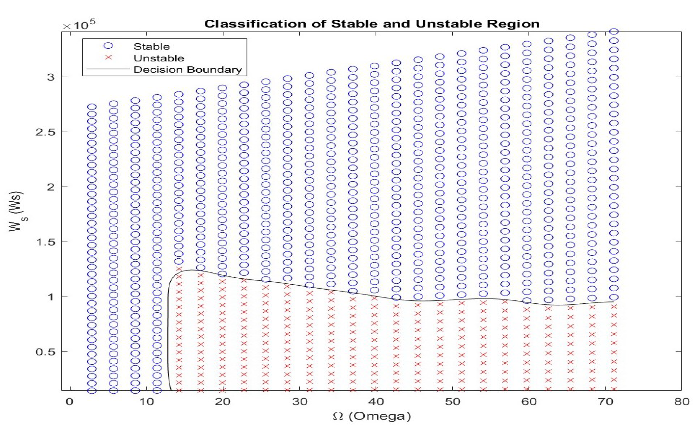
3.2. Safe Operational Region

The rotational speed Ω 0 and the surface weight on bit W s are two crucial parameters that can be readily adjusted in practical drilling operations. In contrast, the cutting coefficient ψ varies as the drill bit encounters different subsurface formations, such as sand or rock. For additional parametric analysis, a stability volume is computed numerically using a linearized version of the drill string model within a three-dimensional space defined by Ω 0 , W s , and ψ . The stability region within this volume is characterized by the system’s behavior as ψ increases from 0.1 to 26.0, showing that the nominal depth of cut at which stable operation is maintained also increases. As illustrated in Figure 1, red crosses indicate combinations of Ω 0 and W s that result in severe drill string vibrations, while blue circles denote combinations that do not lead to significant vibration. The boundary of the stability region is delineated by a solid line, marking the transition between stable and unstable drilling conditions. The boundary of the stability region is marked by a solid line.
By continuously adapting the drillstring model based on real-time data and formation analysis, the safe operational region can be accurately characterized. Real-time monitoring and dynamic analysis enable the method to predict drillstring vibrations and assess their potential impact on drilling performance. By identifying vibration patterns and understanding their correlation with formation characteristics, drilling parameters such as the WOB and RPM can be adjusted proactively to mitigate these vibrations. This proactive approach ensures that the drillstring operates within a safe and efficient range, thereby reducing the risk of equipment failure. Moreover, defining the safe operational region allows for more precise control over the drilling process, contributing to improved efficiency and enhanced safety.

4. ROP Optimization and Control

4.1. ROP Optimization

Although rapid drilling is often desirable to reduce well construction time, it can introduce complications such as poor hole cleaning and increased likelihood of drilling incidents. Therefore, optimizing the drilling process is essential to enhance operational efficiency—by minimizing vibrations, ensuring wellbore quality, and facilitating effective cuttings transport—and ultimately reduce drilling costs. The key to implementing a real-time ROP optimization algorithm lies in achieving predefined objectives, such as maximizing the ROP or minimizing the MSE, while operating within established safety and operational boundaries.
Th work [48] illustrates the ROP contours within the WOB–RPM space, highlighting how certain combinations of parameters can lead to drilling dysfunctions. For instance, a high WOB and low RPM increase the risk of stick–slip vibrations, while high values of both the WOB and RPM may cause backward whirl, potentially damaging downhole equipment. Consequently, selecting the WOB and RPM within a safe and stable operational region is critical to avoiding issues such as vibrations, inefficient drilling, or poor hole cleaning.
This study addresses the ROP optimization problem using a nonlinear constrained optimization approach to determine the optimal WOB and RPM. The solution space is bounded by nonlinear constraints that define the safe operating region. Accurately characterizing this region is inherently complex, as it depends on a range of factors, including hydraulics, mechanical limits, geological variability, and equipment capabilities. Although few studies have tackled this complexity, recent work by [49] proposed a numerical method for estimating stable regions based on vibration behavior. However, their algorithm was constrained by specific assumptions and limited in generality. In this study, we assume the existence of a safe operational envelope and model it through a set of explicit nonlinear inequality constraints:
h i ( WOB , RPM ) 0 , i = 1 , , n c ,
where n c denotes the number of constraint boundaries. These constraints enable the optimization algorithm to avoid unstable drilling regimes while maximizing the ROP. Although the boundaries are predefined in this work, their formulation needs more research regarding adaptive and data-driven definitions of safe drilling zones. In addition to pursuing a higher ROP, optimizing drilling operations should also focus on minimizing the MSE to ensure optimal performance. The cost function can be formulated as follows:
J = M S E .
The physical boundaries considered here are
W O B l W O B W O B u , R P M l R P M R P M u ,
where W O B l is the lower bound of the WOB; W O B u is the upper bound of the WOB; R P M l is the lower bound of the RPM; and R P M u is the upper bound of the RPM. We could frame the optimization problem as the following:
min W O B , R P M J
subject to
W O B l W O B W O B u , R P M l R P M R P M u , R O P = f ( R P M , W O B , α ) , h i ( W O B , R P M ) 0 , i = 1 , , n c .
Here, α represents additional parameters in the ROP model. The optimization is performed with respect to formation hardness, specifically the coefficients a 5 and a 6 , and is constrained by physical and operational boundaries. To enhance clarity on the control strategy, we briefly elaborate on the optimization logic used for the key control parameters—the WOB and RPM. These parameters are optimized through the nonlinear constrained optimization framework (19). This ensures that the selected WOB and RPM values not only improve drilling performance but also mitigate risks such as stick–slip vibrations. The optimization module updates these control setpoints iteratively and feeds them to the control system for execution, enabling a closed-loop, adaptive drilling strategy.
Several numerical solvers are suitable for this type of constrained, nonlinear optimization. Genetic algorithms (GAs) are inspired by natural selection and are well suited for complex, multi-objective problems with large search spaces. They evolve a population of candidate solutions using selection, crossover, and mutation. While effective, GAs can be computationally intensive and require careful parameter tuning. Particle swarm optimization (PSO) mimics the collective behavior of bird flocks or fish schools. It is simple to implement and tends to converge quickly, making it effective for continuous, nonlinear problems. However, PSO may suffer from premature convergence to local optima. Gradient-based nethods, such as gradient descent, are efficient for differentiable objective functions and can rapidly converge to a solution. Their main limitation lies in sensitivity to local optima, especially in highly nonlinear landscapes.

4.2. ROP Control Systems

Modern drilling control systems are based on well-known Proportional–Integral–Derivative (PID) controllers. The ROP is controlled by adjusting the drilling operational parameters, like the WOB and RPM, throughout the drilling operation. The WOB and RPM are the manipulated variables and are automatically adjusted by the control system. The discrete-time PID controller for the WOB is expressed as follows:
z w ( t ) = K p 1 e ( t ) + K i 1 0 t e ( τ ) d τ + K d 1 d e ( t ) d t ,
where
e ( t ) = W O B ( t ) W O B s p ( t ) .
The discrete-time PID controller for RPM is expressed as follows:
z r ( t ) = K p 2 e ( t ) + K i 2 0 t e ( τ ) d τ + K d 2 d e ( t ) d t ,
where
e ( t ) = R P M ( t ) R P M s p ( t ) .
In the PID controllers (20) and (22), z w and z r represent the control commands sent to the actuators. The controller gains include the proportional gain K p , integral gain K i , and derivative gain K d . The gain K p adjusts the system’s response sensitivity, K i eliminates the steady-state error between the measured values and setpoints, and K d helps to reduce overshoot and improve stability by influencing the rate of change. The variables W O B ( t ) and R P M ( t ) represent real-time sensor measurements at time t, while W O B sp ( t ) and R P M sp ( t ) are the corresponding setpoints generated by the control system to guide the measurements toward desired targets. These setpoints are typically determined by the ROP optimization module. The effectiveness of the ROP control relies heavily on the accurate and timely selection of these setpoints. Achieving optimal drilling performance requires a comprehensive understanding of how the WOB and RPM interact with varying formation properties and downhole conditions. Therefore, setpoint selection must be both adaptive and context-aware to ensure efficient and safe drilling operations.

5. Modules Integration
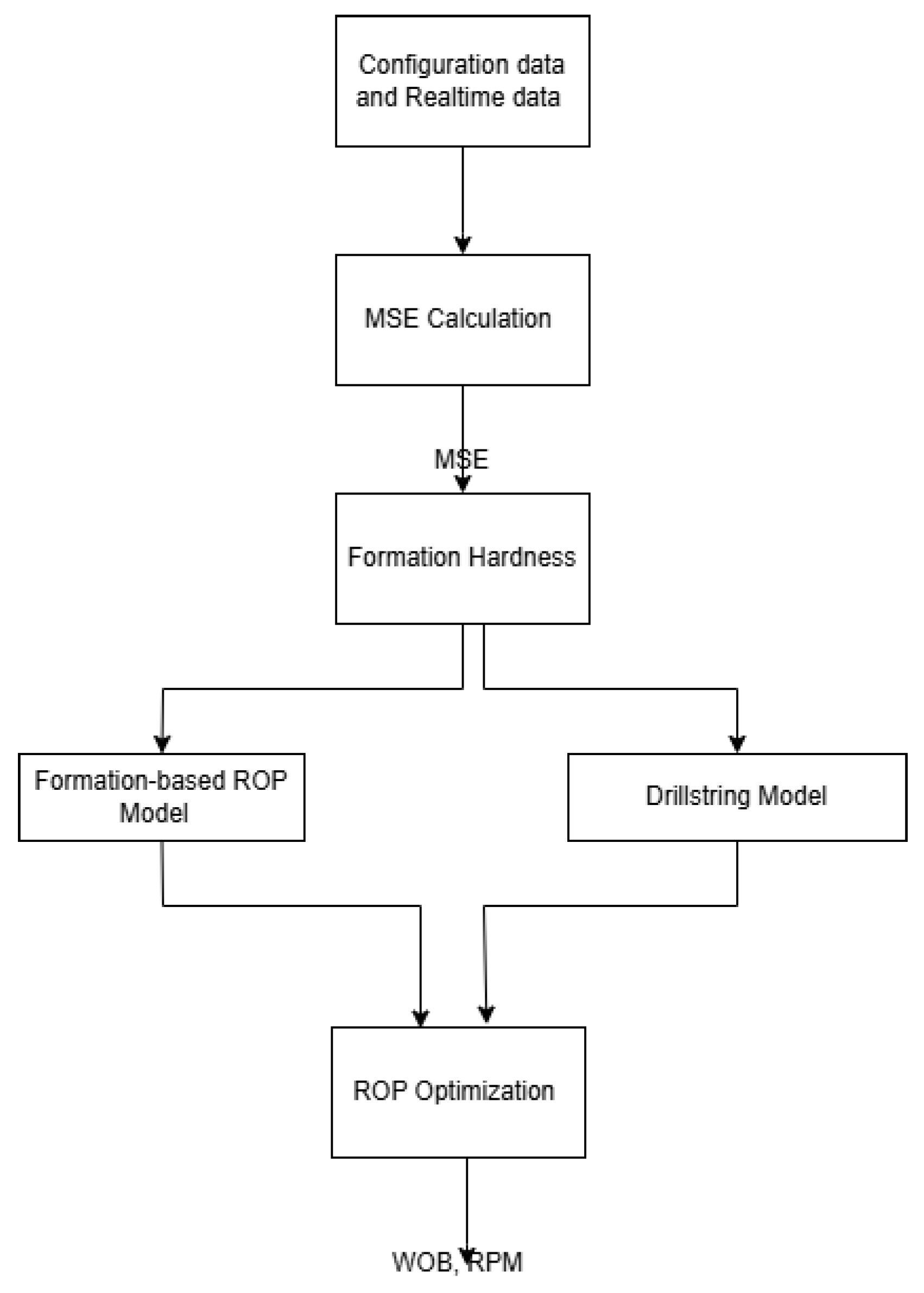
5.1. Flow Chart

The detailed workflow is illustrated in Figure 2. It consists of a sequence of steps that collectively support formation hardness identification, drilling optimization, and real-time trajectory control. The main steps are summarized as follows:
  • MSE Estimation: The process begins with calculating the MSE, including the WOB, RPM, torque, and ROP. The ROP is computed by measuring the drilling distance over a fixed time interval. The MSE serves as the foundational metric for subsequent analysis.
  • Formation Hardness Estimation: Using the MSE, the CCS is estimated, allowing for preliminary classification of formation hardness. This helps anticipate potential drilling challenges and tailor control strategies accordingly.
  • Drillstring Dynamic Modeling: Based on the formation classification, the drillstring model is adapted to reflect downhole conditions. Model parameters are fine-tuned to capture vertical and torsional vibration behavior, enabling definition of the safe operational envelope.
  • ROP Model Adaptation: An appropriate K value is selected for the ROP model according to formation characteristics. This step ensures that the model aligns with the current geological conditions for effective parameter control.
  • ROP Optimization: The optimal WOB and RPM are computed by solving a constrained optimization problem, aiming to maximize the ROP or minimize the MSE while remaining within safety limits.
This workflow exemplifies the integration of sensor data, engineering models, and optimization techniques in modern drilling.

5.2. Applicable Boundaries of the Method

The proposed ROP optimization method is designed for real-time drilling environments where automation, vibration control, and adaptability are critical. Its effective application relies on certain boundary conditions and assumptions that must be acknowledged to ensure safe and accurate performance.
First, the method assumes that a well-defined operational envelope for the WOB and RPM is available. This envelope must reflect the safe limits within which drilling can occur without causing excessive vibrations, bit wear, or hole-cleaning inefficiencies. Inaccurate or poorly defined envelopes may compromise the method’s ability to maintain stability and safety.
Second, the method’s behavior depends on the proper selection and tuning of the ROP and drillstring dynamics models. It is applicable in scenarios where sufficient geological data, bit and mud properties, and downhole environmental parameters (pressure, temperature, etc.) are available and can be integrated into the method. Real-time sensor data are essential to calibrate and adapt the models continuously; hence, it is most effective in environments equipped with modern downhole and surface telemetry systems.
Third, the solver used for optimization must be efficient enough for real-time deployment. The method is best suited for systems where computational resources are adequate to support fast and accurate numerical calculations.
Fourth, the method assumes that PID controllers can be appropriately tuned for the system’s response characteristics. The control system must support continuous tuning and feedback mechanisms to accommodate dynamic drilling conditions.
Finally, while the method accounts for moderate formation variability, it may require recalibration when entering significantly different lithologies or operating environments. Therefore, its application is most reliable in drilling operations with consistent or gradually changing geological conditions or when paired with effective formation change detection algorithms.

6. Case Study

6.1. Problem Description

The ROP model and ROP optimization problem considered in this case study are shown below as
min W O B , R P M M S E
subject to
W O B l W O B W O B u , R P M l R P M R P M u , R O P = K W O B 4 d bit a 5 R P M 60 a 6 , h s ( W O B , R P M ) 0 ,
where h s defines the stable region with low vibration severity, as illustrated in Figure 1. The key challenge in this study is to develop an optimized drilling method that minimizes the MSE while adapting to varying formation parameters across multiple layers. This approach can also address the stick–slip severity and velocity ratio constraints and enable the selection of optimal WOB and RPM settings, leading to low drillstring vibrations. The formation-specific parameters include the following:
  • K: A constant representing the formation’s response to the WOB and RPM.
  • a 5 and a 6 : Exponents that indicate the influence of the WOB and RPM, respectively, on the ROP.
  • WOB and RPM bounds: Upper and lower technique bounds of the WOB and RPM suitable for each formation.
  • UCS: Rock strength, reflecting formation hardness.
  • h s ( W O B , R P M ) : Stable region to maintain safe operation.

6.2. Formation Settings

For this study, we modeled a drilling scenario where the drill bit passes through four unique formation types over a simulated drilling interval of 1000 s. Each formation has distinct properties for the UCS, WOB, RPM, and response coefficients that impact the drilling performance:
  • Formation 1: Soft rock with low UCS (100 MPa) but higher K values, requiring a low RPM to reduce the MSE.
  • Formation 2: A UCS of 120 MPa with moderate K, a 5 , and a 6 values. Optimal performance is expected at 60–120 RPM.
  • Formation 3: A UCS of 80 MPa, highest values for K, and broader RPM bounds (30–150 RPM).
  • Formation 4: Hard rock with a high UCS (150 MPa) suitable for high RPM values within 50–120 RPM.
These settings represent varying conditions encountered in real-world drilling, with each formation’s parameters impacting the optimal WOB and RPM values for efficient and stable drilling.

6.3. Drillstring Dynamic Model

The parameters used in the drillstring model are based on values reported by [37]. The discrete mass M is 3.4 × 10 3 kg, and the discrete rotary inertia I is 116 kg· m 2 . The axial and torsional stiffness are K a = 7 × 10 5 N/m and K t = 938 Nm/rad, respectively. The system’s axial damping coefficient C a is 1.56 × 10 4 Ns/m, while the torsional damping coefficient C t is 32.9 Nms/rad. The rock–bit interaction is modeled using a specific energy of rock ϵ ranging from 0 to 110 MPa and a contact strength σ of 60 MPa. The drill bit has a radius a of 108 mm and a wearflat length of 1.2 mm. The cutter face inclination ζ is 0.6, and the friction coefficient μ between the rock and bit is also 0.6. Additional drill bit geometry parameters include γ = 1 and a blade count n = 4 . The ratio of axial-to-torsional natural frequencies, denoted as η , is 1.6.
We simulated the system using the Euler method with a time step (0.01 s) over a duration of 10 s. The drill string’s axial and angular velocities, dynamic force, and torque were computed iteratively at each time step. The simulation computes both static and dynamic elongations, allowing us to track the total elongation over time and compare it to the nominal drill string length. The initial conditions for position and velocity were set to zero. The simulation loop iteratively updates the state variables (position, velocity, angular velocity, etc.) using the dynamic force and torque to calculate changes in axial and angular velocity over time.

6.4. Optimization Workflow

For each time step in the simulation, the following steps are executed:
  • Formation Check: The current formation is determined based on time. Formation changes introduce significant shifts in optimal settings. When a new formation is detected, the model adjusts the coefficients used in MSE.
  • Objective and Constraints Evaluation: If a new formation is encountered, the MSE objective and constraints are re-evaluated.
  • Optimization: Using MATLAB’s fmincon, the optimization seeks WOB and RPM values that minimize the MSE given the formation’s constraints.
  • Simulation of ROP and MSE: With optimized values, the ROP and MSE are calculated for the current time step.

6.5. Results and Discussions

Figure 3 presents the simulation results of the proposed real-time ROP optimization framework. The evolution of the WOB and RPM illustrates the method’s adaptive response to formation changes. During the initial phase (0–100 s), the WOB and RPM were manually controlled to simulate conventional drilling operations. Once optimization was activated (after 100 s), the method dynamically adjusted both parameters in response to formation transitions, which are represented by discrete changes in the UCS.
An increase in the WOB and RPM was observed at approximately 100 s, corresponding to a transition into a formation with a higher UCS and indicating that greater force and rotational input were required for effective penetration. At around 400 s, both parameters decreased, which is consistent with a shift to a softer formation. A modest increase at 700 s further reflects adaptation to changing lithology. These results demonstrate the method’s ability to track and respond to formation-specific mechanical characteristics in real time.
The predicted ROP closely followed the trends in the WOB and RPM. In harder formations, elevated input parameters yielded higher ROPs, while in softer zones, the method reduced input to maintain stability and energy efficiency. This behavior highlights the method’s capability to optimize penetration performance while respecting operational constraints.
The MSE increased in harder formations due to higher energy requirements and decreased in softer zones, confirming the method’s capacity to balance ROP maximization with energy conservation. The integration of formation change detection and real-time optimization ensures that energy is applied effectively and only when necessary. Despite promising results, several limitations remain. The method is built on simplified assumptions, and real-world complexities such as rock heterogeneity, fluid dynamics, thermal effects, and actuator response delays are not fully captured. Additionally, the stick–slip dynamics are modeled in a reduced form, which may not encompass the full range of torsional and axial interactions encountered during drilling. The absence of field validation further limits the immediate applicability of the findings. Future work should aim to validate the method using field data and implement them within a closed-loop control system that accounts for hardware constraints, safety margins, and equipment durability.

7. Conclusions

This study presents a model-based approach for optimizing the ROP in drilling operations within the oil and gas industry. By dynamically adjusting key operational parameters—specifically the WOB and RPM—in response to changing formation characteristics, the method demonstrates significant potential to improve drilling efficiency and enhance operational stability. Through the integration of formation detection algorithms, the approach enables real-time ROP optimization while maintaining adherence to safe operating boundaries. The goal is to maximize drilling speed and minimize issues such as drillstring vibrations and stick–slip.
However, several limitations remain. The current method relies on simplified assumptions and has not yet been validated under real-world field conditions, which may restrict its applicability across diverse geological formations. Real-time deployment poses practical challenges, as the method presumes accurate and immediate adjustments to the WOB and RPM—capabilities that may not be fully supported by existing drilling equipment. Moreover, the method does not explicitly account for important factors such as tool wear, thermal effects, complex fluid dynamics, and subsurface interactions, potentially limiting its robustness in demanding drilling environments.

8. Future Work

Future work should focus on enhancing the method’s realism by incorporating additional physical and operational factors, such as fluid–structure interactions and tool wear dynamics. Integrating machine learning techniques could improve the method’s adaptability by leveraging real-time data for decision making. Moreover, conducting extensive field trials and validation studies will be essential to refine and evaluate the method, ensuring its practical applicability and effectiveness in modern drilling operations.

Funding

This research received no external funding.

Institutional Review Board Statement

Not applicable.

Informed Consent Statement

Not applicable.

Data Availability Statement

The data supporting the reported results in this study will be made available by the corresponding author upon reasonable request.

Conflicts of Interest

The authors declare no conflicts of interest.

References

  1. Bourgoyne, A.T.; Millheim, K.K.; Chenevert, M.E.; Young, F.S. Applied Drilling Engineering; SPE Textbook Series; Society of Petroleum Engineers, Inc.: Calgary, AB, Canada, 1986. [Google Scholar]
  2. Duklet, C.P.; Bates, T.R. An Empirical Correlation to Predict Diamond Bit Drilling Rates. In Proceedings of the SPE Annual Technical Conference and Exhibition, Dallas, TX, USA, 21–24 September 1980. [Google Scholar] [CrossRef]
  3. de Moura Junior, J. Universal Physics-based Rate of Penetration Prediction Model for Rotary Drilling. Ph.D. Thesis, Faculty of Engineering and Applied Science, Memorial University of Newfoundland, St. John’s, NL, Canada, 2021. [Google Scholar]
  4. Jalakani, R.; Tabatabaee Moradi, S.S. Rate of penetration prediction with uncertainty assessment: Case study of a middle-east oil field. Results Eng. 2024, 21, 101793. [Google Scholar] [CrossRef]
  5. Hegde, C.; Daigle, H.; Millwater, H.; Gray, K. Analysis of rate of penetration (ROP) prediction in drilling using physics-based and data-driven models. J. Pet. Sci. Eng. 2017, 159, 295–306. [Google Scholar] [CrossRef]
  6. Hegde, C.; Gray, K. Evaluation of Coupled Machine Learning Models for Drilling Optimization. J. Nat. Gas Sci. Eng. 2018, 56, 397–407. [Google Scholar] [CrossRef]
  7. Wood, D.A. Chapter 6—Real-time monitoring and optimization of drilling performance using artificial intelligence techniques: A review. In Sustainable Natural Gas Drilling; Wood, D.A., Cai, J., Eds.; The Fundamentals and Sustainable Advances in Natural Gas Science and Eng; Elsevier: Amsterdam, The Netherlands, 2024; Volume 4, pp. 169–210. [Google Scholar] [CrossRef]
  8. Singh, K.; Siddiqui, F.; Braga, D.; Kamyab, M.; Cheatham, C.; Harclerode, B. ROP Optimization using a Hybrid Machine Learning and Physics-Based Multivariate Objective Function with Real-Time Vibration and Stick-Slip Filters. In Proceedings of the IADC/SPE International Drilling Conference and Exhibition, Galveston, TX, USA, 8–10 March 2022. [Google Scholar] [CrossRef]
  9. Tunkiel, A.T.; Sui, D.; Wiktorski, T. Training-while-drilling approach to inclination prediction in directional drilling utilizing recurrent neural networks. J. Pet. Sci. Eng. 2021, 196, 108128. [Google Scholar] [CrossRef]
  10. Madasu, S. A Hybrid Physics/Data Driven Modeling Approach for Virtual Sensors. In Proceedings of the 2020 IEEE International Symposium on Signal Processing and Information Technology (ISSPIT), Louisville, KY, USA, 9–11 December 2020; pp. 1–6. [Google Scholar] [CrossRef]
  11. Wang, Y.; Tan, Q.; Wu, D.; Chen, H.; Hu, N.; Zhao, Y. A Data-Driven Approach to Predict the ROP of Deep Wells in Fukang Sag. Appl. Sci. 2023, 13, 12471. [Google Scholar] [CrossRef]
  12. Al Dushaishi, M.F.; Abbas, A.K.; Al Saba, M.T.; Wise, J. Drilling Optimization Using Artificial Neural Networks and Empirical Models. ChemEngineering 2025, 9, 37. [Google Scholar] [CrossRef]
  13. Elkatatny, S. Real-time prediction of rate of penetration while drilling complex lithologies using artificial intelligence techniques. Ain Shams Eng. J. 2021, 12, 917–926. [Google Scholar] [CrossRef]
  14. Liu, Y.; Zhang, W.; Li, X. Application of machine learning algorithms for ROP prediction in complex geological conditions. Energy Rep. 2021, 7, 289–300. [Google Scholar]
  15. Salih, N.; Ksantini, M.; Hussein, N.; Halima, D.B.; Razzaq, A.A.; Ahmed, S. Prediction of ROP Zones Using Deep Learning Algorithms and Voting Classifier Technique. Int. J. Comput. Intell. Syst. 2023, 16, 86. [Google Scholar] [CrossRef]
  16. Lee, C.; Kim, J.; Kim, N.; Ki, S.; Seo, J.; Park, C. Evaluating the Rate of Penetration with Deep-Learning Predictive Models. Int. J. Energy Res. 2025. [Google Scholar] [CrossRef]
  17. Jiao, S.; Li, W.; Li, Z.; Gai, J.; Zou, L.; Su, Y. Hybrid Physics-Machine Learning Models for Predicting Rate of Penetration in the Halahatang Oil Field, Tarim Basin. Sci. Rep. 2024, 14, 5957. [Google Scholar] [CrossRef] [PubMed]
  18. Hegde, C.; Soares, C.; Gray, K. Rate of Penetration (ROP) Modeling Using Hybrid Models: Deterministic and Machine Learning. In Proceedings of the SPE/AAPG/SEG Unconventional Resources Technology Conference, Houston, TX, USA, 23–25 July 2018. [Google Scholar] [CrossRef]
  19. Yang, Y.; Cen, X.; Ni, H.; Liu, Y.; Chen, Z.J.; Yang, J.; Hong, B. A highly accurate and robust prediction framework for drilling rate of penetration based on machine learning ensemble algorithm. Geoenergy Sci. Eng. 2025, 244, 213423. [Google Scholar] [CrossRef]
  20. Bourgoyne, A.T.; Young, F.S. A new approach to the analysis of the performance of roller cone bits. J. Pet. Technol. 1974, 26, 497–505. [Google Scholar]
  21. Hareland, G.; Rampersad, K. Application of drilling optimization using response surface methodology. J. Can. Pet. Technol. 1994, 33, 38–45. [Google Scholar]
  22. Joy, G.; Abish, J.; Samuel, R. Fast Drilling Optimizer for Drilling Automation. In Proceedings of the SPE Western Regional Meeting, Virtual, 20–22 April 2021. [Google Scholar] [CrossRef]
  23. Duru, D.; Kerunwa, A.; Odo, J. Application of Genetic Algorithm on Data Driven Models for Optimized ROP Prediction. Presented at the SPE Nigeria Annual International Conference and Exhibition, Lagos, Nigeria, 1–3 August 2022. [Google Scholar] [CrossRef]
  24. Chen, X.; Du, X.; Weng, C.; Yang, J.; Gao, D.; Su, D.; Wang, G. A real-time drilling parameters optimization method for offshore large-scale cluster extended reach drilling based on intelligent optimization algorithm and machine learning. Ocean. Eng. 2024, 291, 116375. [Google Scholar] [CrossRef]
  25. Wang, J.; Yan, Z.; Pan, T.; Zhu, Z.; Song, X.; Yang, D. Drilling Parameters Multi-Objective Optimization Method Based on PSO-Bi-LSTM. Appl. Sci. 2023, 13, 11666. [Google Scholar] [CrossRef]
  26. Sobhi, I.; Dobbi, A.; Hachana, O. Prediction and Analysis of Penetration Rate in Drilling Operation Using Deterministic and Metaheuristic Optimization Methods. J. Pet. Explor. Prod. Technol. 2022, 12, 1341–1352. [Google Scholar] [CrossRef]
  27. Huang, X.; Luu, T.P.; Furlong, T.; Bomidi, J. Deep Reinforcement Learning for Automatic Drilling Optimization Using an Integrated Reward Function. In Proceedings of the IADC/SPE International Drilling Conference and Exhibition, Galveston, TX, USA, 5–7 March 2024. [Google Scholar] [CrossRef]
  28. Teale, R. The concept of specific energy in rock drilling. Int. J. Rock Mech. Min. Sci. Geomech. Abstr. 1965, 2, 57–73. [Google Scholar] [CrossRef]
  29. Dupriest, F.E.; Koederitz, W.L. Maximizing drill rates with real-time surveillance of mechanical specific energy. In Proceedings of the SPE Annual Technical Conference and Exhibition, Dallas, TX, USA, 9–12 October 2005. [Google Scholar]
  30. Anemangely, M.; Ramezanzadeh, A.; Mohammadi Behboud, M. Geomechanical parameter estimation from mechanical specific energy using artificial intelligence. J. Pet. Sci. Eng. 2019, 175, 407–429. [Google Scholar] [CrossRef]
  31. Hammoutene, C.; Bits, S. FEA Modelled MSE/UCS Values Optimise PDC Design for Entire Hole Section. In Proceedings of the North Africa Technical Conference and Exhibition, Cairo, Egypt, 20–22 February 2012. [Google Scholar] [CrossRef]
  32. Deere, D.U.; Miller, R.P. Engineering Classification and Index Properties for Intact Rock; Technical Report; University of Illinois: Urbana, IL, USA, 1996. [Google Scholar]
  33. Navarro-López, E.M.; Suárez, R. Practical Approach to Modelling and Controlling Stick-Slip Oscillations in Oilwell Drillstrings. In Proceedings of the IEEE International Conference on Control Applications, Taipei, Taiwan, 2–4 September 2004; Volume 2, pp. 1454–1460. [Google Scholar]
  34. Leine, R.I.; van Campen, D.H. Stick-Slip Whirl Interaction in Drillstring Dynamics. In IUTAM Symposium on Chaotic Dynamics and Control of Systems and Processes in Mechanics; Rega, G., Vestroni, F., Eds.; Solid Mechanics and Its Applications; Springer: Dordrecht, The Netherlands, 2005; Volume 122. [Google Scholar] [CrossRef]
  35. Richard, T.; Germay, C.; Detournay, E. A simplified model to explore the root cause of stick–slip vibrations in drilling systems with drag bits. J. Sound Vib. 2007, 305, 432–456. [Google Scholar] [CrossRef]
  36. Yigit, A.S.; Christoforou, A.P. Stick-Slip and Bit-Bounce Interaction in Oil-Well Drillstrings. J. Energy Resour. Technol. 2006, 128, 268–274. [Google Scholar] [CrossRef]
  37. Liu, X.; Vlajic, N.; Long, X.; Meng, G.; Balachandran, B. Coupled axial-torsional dynamics in rotary drilling with state-dependent delay: Stability and control. J. Sound Vib. 2014, 333, 2365–2380. [Google Scholar] [CrossRef]
  38. Faghihi, M.A.; Mohammadi, H.; Yazdi, E.A.; Eghtesad, M.; Tashakori, S. Distributed model for the drill-string system with multiple regenerative effects in the bit-rock interaction. J. Sound Vib. 2024, 571, 118120. [Google Scholar] [CrossRef]
  39. Li, B.; Zhu, X.; Dong, L. Axial transfer characteristics of a drillstring in conjunction with bit penetration behavior in horizontal wells. Geoenergy Sci. Eng. 2024, 240, 212989. [Google Scholar] [CrossRef]
  40. Han, Y.; Kuang, Y.; Yang, B.; Ai, Z. Nonlinear Dynamic Modeling of Drillstring-Bit-Rock Coupling System Based on Bit/Rock Interaction Simulation. SPE J. 2022, 27, 2161–2182. [Google Scholar] [CrossRef]
  41. Khulief, Y.; Al-Naser, H. Finite element dynamic analysis of drillstrings. Finite Elem. Anal. Des. 2005, 41, 1270–1288. [Google Scholar] [CrossRef]
  42. Feng, T.; Vadali, M.; Ma, Z.; Chen, D.; Dykstra, J. A Finite Element Method with Full Bit-Force Modeling to Analyze Drillstring Vibration. J. Dyn. Syst. Meas. Control 2017, 139, 091016. [Google Scholar] [CrossRef]
  43. Tucker, W.; Wang, C. On the Effective Control of Torsional Vibrations in Drilling Systems. J. Sound Vib. 1999, 224, 101–122. [Google Scholar] [CrossRef]
  44. Noabahar Sadeghi, A.; Arıkan, K.B.; Özbek, M.E. Modelling and controlling of drill string stick slip vibrations in an oil well drilling rig. J. Pet. Sci. Eng. 2022, 216, 110759. [Google Scholar] [CrossRef]
  45. Germay, C.; Van de Wouw, N.; Nijmeijer, H.; Sepulchre, R. Nonlinear Drillstring Dynamics Analysis. SIAM J. Appl. Dyn. Syst. 2009, 8, 527–553. [Google Scholar] [CrossRef]
  46. Cunha, A., Jr.; Soize, C.; Sampaio, R. Analysis of the Nonlinear Dynamics of a Horizontal Drillstring. In Proceedings of the 9th International Conference on Structural Dynamics, EURODYN 2014, EASD, Porto, Portugal, 30 June–2 July 2014; pp. 2057–2061. [Google Scholar]
  47. Detournay, E.; Defourny, P. A phenomenological model for the drilling action of drag bits. Int. J. Rock Mech. Min. Sci. Geomech. Abstr. 1992, 29, 13–23. [Google Scholar] [CrossRef]
  48. Løken, E.A.; Løkkevik, J.; Sui, D. Implementation of Automated Drilling Algorithms on a Laboratory Drilling Rig. Model. Identif. Control 2020, 41, 1–11. [Google Scholar] [CrossRef]
  49. Tengesdal, N.K.; Hovda, S.; Holden, C. A discussion on the decoupling assumption of axial and torsional dynamics in bit-rock models. J. Pet. Sci. Eng. 2021, 202, 108070. [Google Scholar] [CrossRef]
Figure 1. Stable region for drillstring movement.
Fuels 06 00033 g001
Figure 2. Flowchart of ROP optimization.
Fuels 06 00033 g002
Figure 3. ROP optimization result.
Fuels 06 00033 g003
Disclaimer/Publisher’s Note: The statements, opinions and data contained in all publications are solely those of the individual author(s) and contributor(s) and not of MDPI and/or the editor(s). MDPI and/or the editor(s) disclaim responsibility for any injury to people or property resulting from any ideas, methods, instructions or products referred to in the content.

