Article

Gas Hydrate Plugging Mechanisms during Transient Shut–In/Restart Operation in Fully Dispersed Systems

1
Center for Hydrate Research, Department of Chemical and Biological Engineering, Colorado School of Mines, 1600 Illinois Street, Golden, CO 80401, USA
2
Department of Chemical and Process Engineering Technology, Universiti Malaysia Pahang Al–Sultan Abdullah, Lebuh Persiaran Tun Khalil Yaakob, Kuantan 26300, Pahang, Malaysia
3
Department of Petroleum Engineering, Colorado School of Mines, 1600 Arapahoe Street, Golden, CO 80401, USA
*
Author to whom correspondence should be addressed.
Fuels 2024, 5(3), 297-316; https://doi.org/10.3390/fuels5030017
Submission received: 26 April 2024 / Revised: 24 May 2024 / Accepted: 8 July 2024 / Published: 16 July 2024

Abstract

:
Gas hydrate formation poses a significant challenge in offshore oil and gas production, particularly during cold restarts after extended shut–ins, which can lead to pipeline blockages. Although steady–state models have traditionally been used to predict hydrate formation under continuous production conditions, these models are often inadequate for transient operations due to issues like near–zero fluid flow shear affecting the viscosity calculations of hydrate slurries. This study introduces novel conceptual models for dispersed water–in–crude oil systems specifically designed for cold restart scenarios. The models are supported by direct observations and various experimental approaches, including bottle tests, rheometer measurements, micromechanical force apparatus, and rocking cell studies, which elucidate the underlying mechanisms of hydrate formation. Additionally, this work introduces a modeling approach to represent conceptual pictures, incorporating particle settling and yield stress, to determine whether the system will plug or not upon restart. Validation is provided through transient large–scale flowloop tests, confirming the plugging mechanisms outlined. This comprehensive approach offers insights into conditions that may safely prevent or potentially lead to blockages in the fully dispersed system during field restarts, thereby enhancing the understanding and management of gas hydrate risks in offshore oil and gas operations.

1. Introduction

Solid ice–like substances that form when water cages enclose guest gas molecules under low–temperature and high–pressure conditions are known as clathrate gas hydrates [1]. The formation of gas hydrates was first reported in the early 1800s, when gases like chlorine were combined with water to form a solid, marking the initiation of the general clathrate gas hydrate research [2,3]. The interests in gas hydrates in the oil and gas industry mainly center around their potential to cause flow assurance issues, where it was first reported in 1934 that gas hydrates formed in natural gas transmission pipelines create blockages [4]. This study sparked a significant increase in industry–wide research aimed at understanding, preventing, and mitigating gas hydrate formation.
The concept of flow assurance was introduced by Petrobras in the early 1990s [5]. It describes the comprehensive discipline focused on the efficient transport of hydrocarbons from reservoirs to processing facilities, ensuring safety, efficiency, and economic viability throughout the entire field lifecycle [6]. Primary challenges in flow assurance include hydrate formation [7], wax and paraffin build–up [8], asphaltene precipitation [9], and scale formation [10]. As oil and gas exploration and production moved to more challenging environments, the scope has broadened to include corrosion [11], emulsions [12], and erosions due to sand production [13].
Most production flowlines are an ideal environment to form hydrates, as these pipelines meet the necessary high–pressure conditions inherent to reservoir conditions. The temperature criteria are subsequently achieved in both subsea and onshore pipelines due to ambient cooling from seawater and winter air temperatures for oil–dominated cases. Due to the rapid formation of hydrate [14], most operator companies adopted conservative hydrate design philosophies that eliminated hydrate–related risks. This involves equipping pipelines with heating systems, creating facilities for quick pipe depressurization, and injecting thermodynamic hydrate inhibitors, among other strategies [15]. The aim is to ensure that the subsea system rarely encounters conditions conducive to hydrate formation.
As a result, most systems are engineered to maintain temperatures sufficiently high to prevent hydrate formation during steady–state operations [16]. However, during shut–ins, the temperature and pressure conditions typically fall within the hydrate thermodynamic equilibrium conditions, posing a significant risk of hydrate formation and potential blockages upon restart, when hydrate mitigation strategies are not properly and timely implemented. To effectively address the high–risk periods associated with hydrate formation during shut–in and restart operations, a detailed and comprehensive understanding of hydrate formation and plugging mechanisms is essential.
To investigate the plugging mechanism caused by hydrates, a variety of multiscale experimental setups are employed. These include interfacial tests, such as low– and high–pressure micromechanical force (MMF) measurements, contact angle measurements, high–pressure differential scanning calorimetry (HP–DSC), and bottle tests. Additionally, there are bench–scale evaluations utilizing rheometers, autoclaves, and rocking cells, complemented by pilot–scale flowloop experiments. Together, these experimental methodologies break down the complex process of hydrate formation and blockage into measurable variables, advancing our understanding of the fundamental mechanisms involved.
Based on identified mechanisms, conceptual pictures have been developed that advance innovative experimental setups, hydrate management strategies, and predictive models. These conceptual pictures particularly address two prevalent scenarios in the oil and gas sector: emulsified (dispersed) and non–emulsified (segregated) distribution of water and oil [17]. Turner et al. laid the groundwork for the emulsified systems by introducing a conceptual illustration of the gas hydrate plugging formation in oil–continuous systems during continuous production, as depicted in Figure 1. In essence, the model delineates a sequential four–stage mechanism: (1) emulsification of the water phase within the oil, (2) initiation of hydrate nucleation and growth at the individual water droplet surfaces, (3) aggregate formation from agglomeration of gas hydrate shelled– or fully converted hydrate particles, and (4) plugging due to jammed aggregates [18].
For the non–emulsified system, Pickarts et al. presented a conceptual illustration of transient conditions using data from the previously mentioned multiscale experiments [19]. Their study, grounded on results obtained with model oil lacking surfactants or other mitigation measures, highlighted the role of phase separation and water pooling during shut–in. This process leads to the formation of low–conversion, liquid–filled hydrate deposits.
However, the scenario of operating without mitigation efforts in real fields is unlikely. The presence of natural surfactant components in the bulk hydrocarbon phase that stabilize water–in–oil dispersions makes crude oil systems behave differently from gas condensate systems in terms of plugging mechanisms [20]. Even though in a stagnant condition crude oil systems may lose the mixing energy to maintain the water phase dispersed, the emulsion may still remain for an extended period, often lasting several days without coalescence or phase separation [17]. The complex crude oil chemistry can greatly affect the interfacial behaviors of hydrates and may lead to more severe situations [21].
Conceptual pictures have served as guidelines for model development and simulations [22]. However, the model developed based on steady–state conceptual pictures for oil–dominated systems, as depicted in Figure 1, which calculates the hydrate particle size, hydrate agglomerate size, and hydrate slurry viscosity, cannot simulate the shut–in condition due to the zero shear rate. Therefore, it is crucial to expand the framework to include descriptions of the hydrate plugging mechanism during shut–in and restart to ultimately guide simulations of hydrate plugging in the fully dispersed system during transient operations, especially for a high GOR fluid when the hydrate formation process is not self–limiting [23]. This work attempts to fill the knowledge gap by providing a conceptual illustration outlining the specific phenomena during the shut–in and restart of water–in–oil dispersed systems (i.e., liquid hydrocarbon phase with natural surfactants). The processes of water droplet and hydrate particle settling during shut–in and the formation of hydrate aggregates with yield stress during restart is analyzed to provide an understanding of fundamental concepts. This new formulation expands the framework of original plugging conceptual pictures and provides the basis necessary for the development of hydrate risk predictive models, transient operation guidelines, and best practices.

2. Conceptual Pictures for Transient Operations of Dispersed Systems

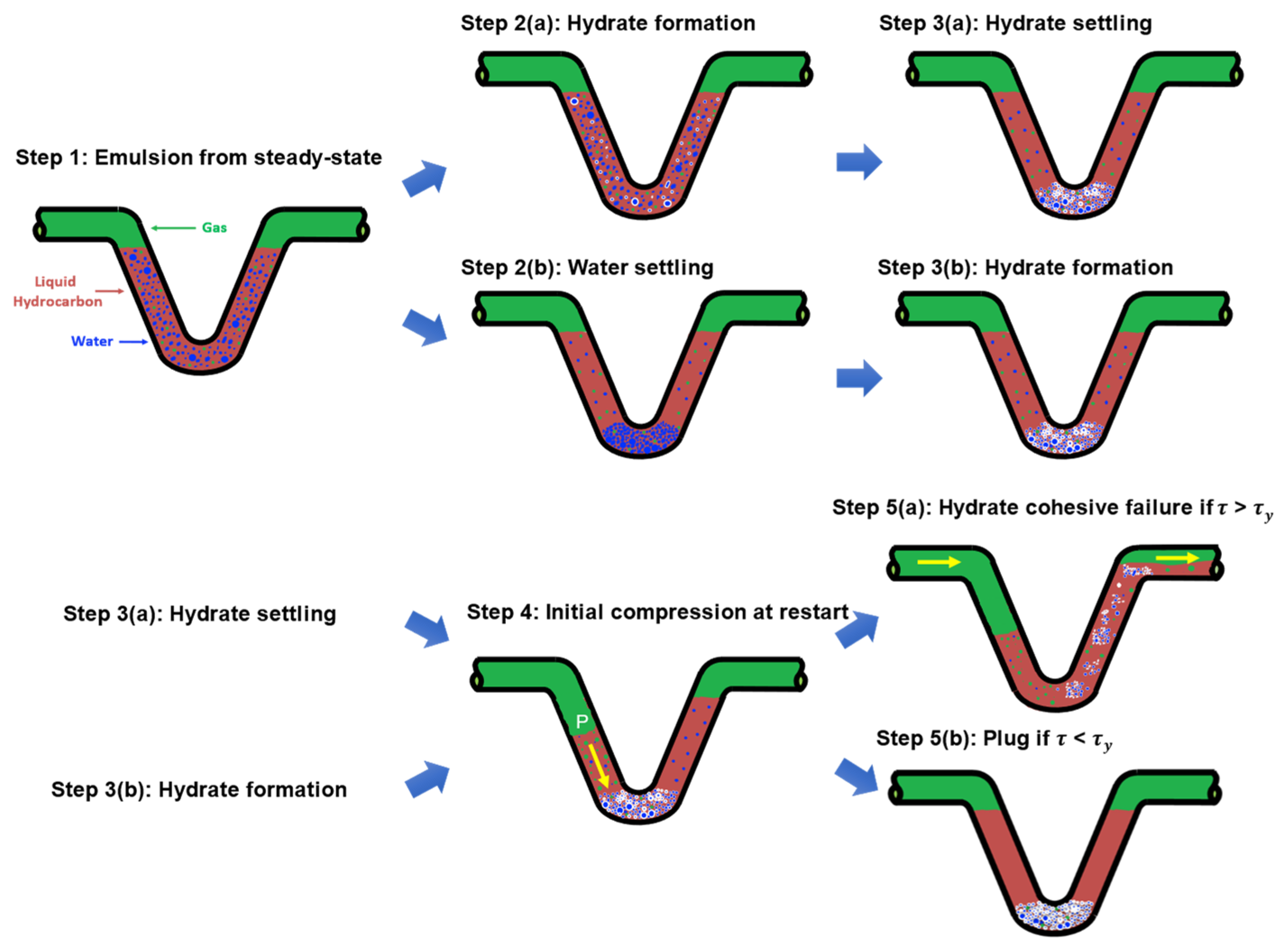
Figure 2 provides comprehensive conceptual pictures of the gas hydrate formation process during the transient shut–in and restart in a fully dispersed system. The subsequent sections will elaborate on each step in detail.

2.1. Step 1: Emulsifying and Water Droplet Settling during Shut–In

In the event of an emergency or equipment malfunction, a producing flowline is shut down. Initially, it typically operates outside the gas hydrate stability zone. Due to the presence of surface–active components in the oil–continuous phase and interfacial mechanisms at the boundary of dispersed water droplets, the fluid at shut–in involves a stable emulsion. This means that the coalescence of the dispersed phase is significantly delayed, and individual water droplets remain dispersed within the oil phase, preventing the formation of a distinct water phase that could accumulate at the lower spots of the flowline even during stagnant conditions. However, it is still possible for water droplets to settle in the pipeline, potentially forming a structure with hydrate particles that leads to a plug. Therefore, a model should be applied to evaluate this settling behavior.
The effects of particle diameter and phase density have been experimentally investigated for hydrate systems [24]. The hindered settling model, an extension of Stoke’s law, which was originally intended for a single spherical particle, has also been explored in different systems, such as wax and sand particle systems [25,26]. These investigations have expanded the application of the model to account for the settling behaviors of solutions filled with numerous small and spherical particles in a viscous fluid, similar to the scenario under discussion. As shown in Equation (1), the settling velocity of water droplets in the water–in–oil emulsion is directly proportional to both the density gradient, in the unit of kg/m3, between the dispersed phase and the continuous phase ( ρ d ρ c ) and the droplet size (dp), in the unit of m. It is inversely related to the dynamic viscosity of the continuous phase ( μ c ), in the unit of Pa · s. Moreover, the particle volumetric concentration in the mixture ( α ) is incorporated to consider the interactions between one particle and a multitude of similar neighboring particles. The shape factor ( φ s ) is also introduced to accommodate variations in particle shapes that deviate from a spherical form. In this context, φ s ranges from 0 to 1, with 1 representing a completely spherical shape [27].
v s e t t l i n g = ρ d ρ c g d p 2 18 μ c 1 α 1 + 2.5 α φ s
The physical properties of crude oil, such as density and viscosity, can differ based on the specific offshore fields and the state of the oil. These variations are influenced by whether the oil is in a dead oil, unsaturated, or saturated state. Typically, the viscosity of crude oils from these conditions is expected to fall within the range from 0.25 to 100 cP [28,29]. Additionally, the API gravity is generally within the range from 20° to 50° for these oils, corresponding to density in the range from 0.78 to 0.93 g/cm3. In the context of oil–water mixtures, the size of water droplets present in the oil can be varied in a wide range from 2 to 100 μ m in diameter [30,31]. Figure 3 illustrates the settling velocity change over different particle diameters and fluid viscosities, by assuming a constant crude oil density of 0.8 g/cm3. It should be noted that the travelling distance of the droplets will be assumed to be the pipe diameter for a horizontal pipeline or vertical distance for an inclined pipeline, and the settling velocity will be converted to settling time from the travelling distance for further analysis.
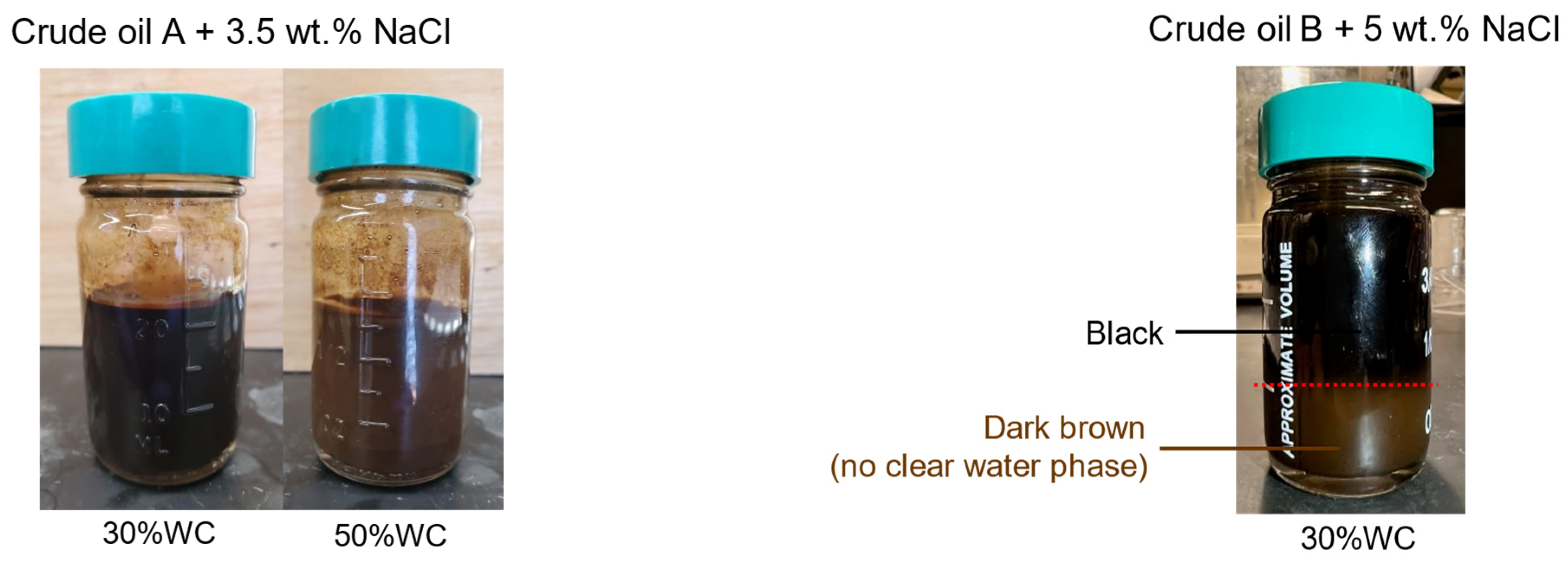
Two crude oils, namely Crudes A and B, were selected to verify the emulsion stability and settling behaviors. The characterization of the oils, preparation of the emulsions, and bottle tests were conducted following the methods reported by Salmin et al. [32]. The API gravities of Crudes A and B were 19.8° and 24.2°, respectively, with asphaltene contents of 0 wt.% for Crude A and 3.1 wt.% for Crude B. When oil possesses a lower API gravity, indicating a higher density, the density difference between oil and water decreases. This reduced density gradient, as described in Equation (1), results in a slower settling velocity for the oil. Consequently, water droplets will be dispersed homogeneously within the system for a significant amount of time, as illustrated in the first step in Figure 2. This conceptual picture is confirmed by the bottle test results using Crude A at 30 vol% and 50 vol% water cuts shown in Figure 4 (left). The observations indicate that the water–in–oil (w/o) emulsion remains stable without any distinct water phase for over 24 h at 20 °C. Notably, the color of 50 vol.% WC appears consistently lighter than 30% WC, suggesting a homogeneous distribution of water droplets in the oil–continuous system.
On the contrary, when the oil has a lower API gravity, which results in a more pronounced difference in density between the oil and water, or when the droplet size is larger, there will be an increase in the settling velocity, as illustrated in the step 2(b) in Figure 2. Figure 4 (right) presents a bottle test using Crude B. Here, the water cut stands at 50 vol.% and salt concentration is at 5 wt.%. The bottle test reveals two distinct layers: a top layer colored black, characteristic of crude oil, and a bottom dark brown layer, which is mainly attributed to the blending of emulsified water droplets with the crude oil.

2.2. Steps 2 and 3: Hydrate Particle Formation

During shut–in, the operators focus on two key time periods: the no–touch time and the cooldown time. The no–touch time is the period when no action is required to restart without hydrate issues, and the cooldown time is the duration it takes for the fluid temperature to drop into the hydrate formation temperature for a given pipeline shut–in pressure [33,34]. During the cooldown time when the temperature enters the hydrate equilibrium region, hydrate starts forming as a shell around the surface of water droplets. Cooldown time is influenced by two key factors: the thermal insulation parameters (such as heat capacity of the pipe material and its overall heat transfer coefficient) and the system–dependent variables, including flowline length, flow rates, flowing wellhead temperatures, shut–in pressure, fluid GOR, and water cut. Typically, pipes are designed to have a cooldown period ranging from 6 to 24 h, but will also change with the lifecycle of production conditions [15,23].
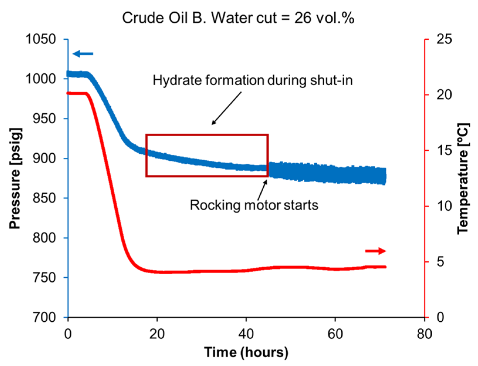
Hydrate is able to form during shut–in conditions. This can be verified with a P–T diagram, which is a standard practice in flow assurance analysis. The rocking cell test is performed using the setup presented by Salmin et al. [32]. The transient protocol is used to run the test. The motor is stopped and maintained in the horizontal position for 24 h. In the first 4 h, the liquid becomes saturated with the gas mixture, and the pressure and temperature stabilize at 1000 psig and 20 °C, respectively. Then, the chiller is set to reach 4 °C over the next 8 h and is maintained at 4 °C for 24 h. Rocking is restarted at 20 rocks per minute after. Figure 5 shows the pressure and temperature profiles of this transient test for the Crude B with 26 vol.% water cut. It is observed that, during a 24 h shut–in period, before the rocking motor is started, the pressure profile decreases when the temperature remains constant, which suggests hydrate formation during shut–in.
The generation of a hydrate particle network in stagnant conditions can be influenced by two types of interactions: between hydrate particles and water droplets, and among hydrate particles themselves. In the first scenario, if the settling time, as calculated from Equation (1), exceeds the cooldown time, then during the settling period, water droplets are likely to collide with hydrate particles. This collision contributes to the formation of the hydrate particle network. In contrast, the second scenario occurs when the settling time is shorter than the cooldown time. In this case, the contact between the hydrate particles themselves leads to the hydrate particle network formation. It should be noted that emulsion destabilization or inversion due to the formation of hydrate, as previously suggested by Høiland et al. [34], was not considered in this work.

2.2.1. Steps 2(a) and 3(a): Water–Hydrate Interaction Dominates

If the settling time for water droplets exceeds the cooldown time while still in the similar order of magnitude, as hydrate forms on the outer surface of most water droplets, the settling of water droplets in step 1 is still ongoing. The movement of water droplets will lead to collisions between the water droplets and hydrate particles. Step 2(a) and 3(a) in Figure 2 summarizes how a hydrate network is generated in this step.
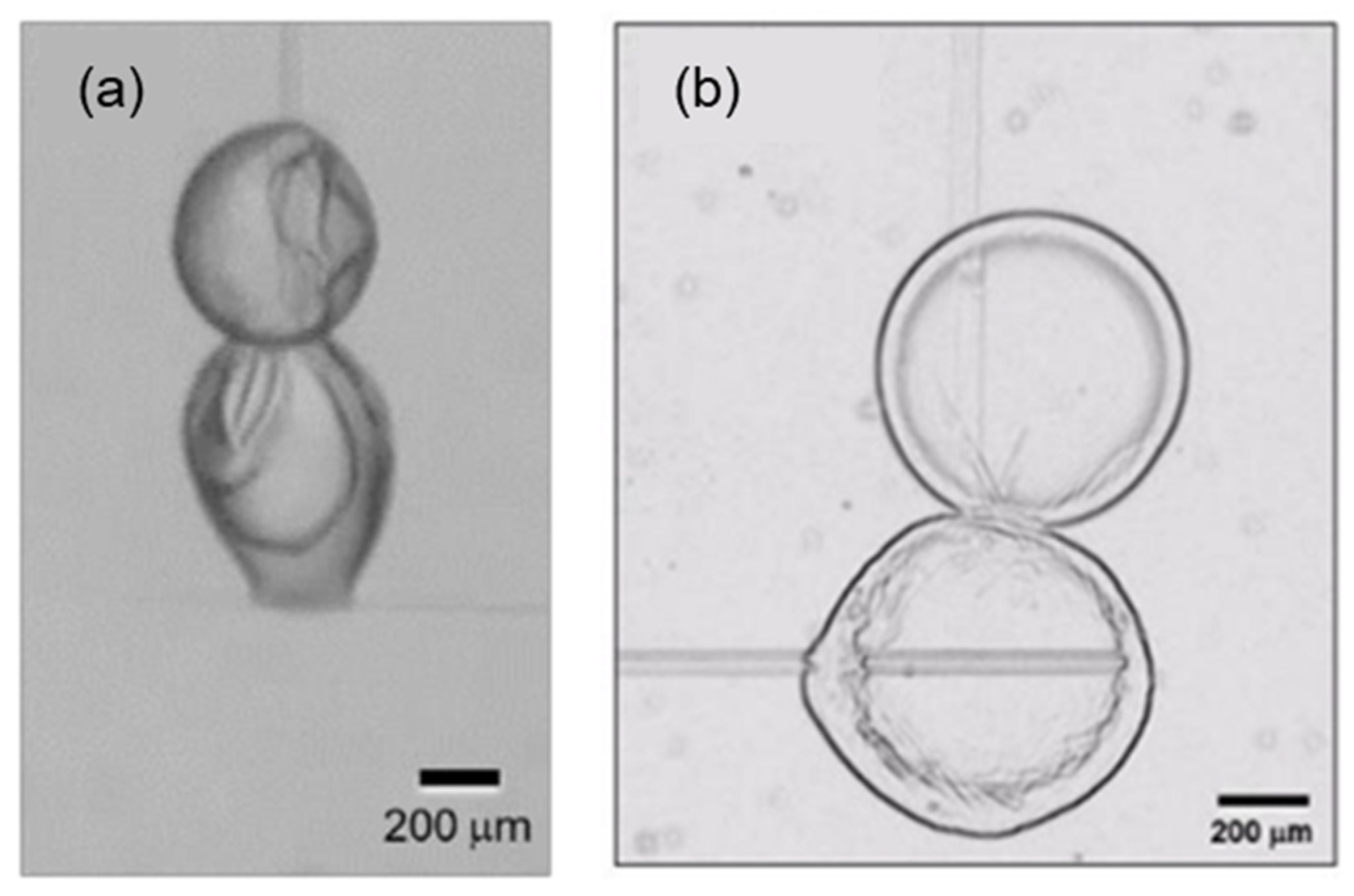
The gas hydrate–water interaction was first examined using both experimental methods in a loop gas lift reactor [35] and a population balance model [36]. To further study this interaction, experiments were conducted under both low– and high–pressure MMF measurements to investigate the interaction between hydrate particles with water droplets in model oil MO70T and crude oil, namely Crude C (API gravity of 40.6° and asphaltene content of 0.85 wt.%). The experimental setup is described in a previous publication [37]. The procedure used in this paper is similar to that reported in [37], except that the hydrate particle at the bottom is replaced with a water droplet. Figure 6a shows the interaction of water droplet and the sII CH4/C2H6 hydrate particle in HP–MMF at the subcooling temperature of 1.7 °C and the pressure of 500 psig. It is found that, in the end, even though the water droplet is not fully converted to hydrate, the two particles bond strongly to each other and are inseparable. Figure 6b demonstrates the contact between the sII cyclopentane hydrate particle and water droplet in low–pressure MMF in cyclopentane with 0.02 vol.% concentration of the Crude C at the subcooling temperature of 1.7 °C. The hydrate film propagation across the water droplet is observed at about 120 s after the initial contact with the hydrate particle. It was found that the cohesive forces between the hydrate–droplet are five to seven times larger than the forces between two hydrate particles in the non–plugging oil systems, which is consistent with conclusions draw from measurement with cyclopentane hydrates [38,39]. Consequently, the ongoing contact between the remaining unconverted water droplets and hydrate particles can result in the formation of a strong structure of hydrate aggregates, which generates high yield stress during restart.
At the beginning of the settling process before hydrate formation, the dispersion of water droplets is stabilized. When two water droplets within an emulsion come close together, the liquid film between them tends to thin out but resist rupturing. This resistance is mainly due to electric double layer, steric repulsion, and/or Marangoni–Gibbs effect, which contribute to the overall stability of the emulsion [20]. In the presence of ionic surfactants and asphaltenes that carry an intrinsic charge, the liquid–liquid interface exhibits a distribution of charges as a result of adsorption of those surfactants. The charged surfaces will repel each other, thereby inhibiting coalescence and agglomeration [40]. In terms of steric repulsion, surfactant chains adsorb onto the water droplets, creating physical barriers. These barriers prevent the droplets from coalescing and from the liquid film draining away. Synergistically, within the Marangoni–Gibbs effect mechanism, the movement of droplets influences the drainage of the liquid film between them. This drainage moves the surfactants to the sides, creating a gradient in interfacial tension. Consequently, this interfacial tension gradient acts as a driving force, causing surfactants to flow from the sides back towards the center of the interface. This movement of surfactants also carries fluid along with it towards the center, effectively replenishing the liquid film between the droplets and helping to maintain its stability [41].
However, the formation of a hydrate shell around droplets can alter the stability of the dispersion due to the impact of the hydrate film. Multiple studies have conducted molecular dynamics simulations and have shown that, when surfactants adsorb on hydrate surfaces, at certain surfactant concentrations, the surfactants position themselves flat against the hydrate, instead of protruding outward as they do on water droplets [42,43]. This flat orientation on hydrates eliminates or reduces effects leading to emulsion stability that are present for water droplets. The mechanisms that maintain the dispersion disappear, and the liquid film between particles can drain more easily, leading to increased contact and higher cohesive force between the water droplet and the hydrate particle [44].

2.2.2. Steps 2(b) and 3(b): Hydrate–Hydrate Interaction Dominates

If the settling time for water droplets is shorter than the cooldown time, water droplets will firstly settle down, and then the hydrate forms outside of the settled water droplets. As the hydrate particles are subject to contact with each other, sintering between particles will occur, which will contribute to yield stress. Step 2(b) and 3(b) in Figure 2 summarizes how the hydrate network is generated in this step.
The influence of contact time on the cohesive forces of CH4/C2H6 hydrates in model oil and 5 vol% of different crude oils was evaluated using the HP–MMF technique. In the experiment, contact time is referred to as the duration of interaction between two independent gas hydrate particles, ranging from 10 s to 18 h. Observations indicate that both model oil and crude oils (including both non–plugging and plugging types) exhibit a similar trend, with cohesive forces increasing over contact times due to hydrate sintering [45]. Additionally, it was discovered that, with both 5 vol.% and 100 vol.% concentrations of plugging oil, the particles become inseparable after 18 h of contact, and the cohesive force exceeds the measurement limit of the calibrated fiber in the equipment, which is 150 mN/m.

2.3. Step 4: Hydrate Compression before Flowing

Once the system maintenance concludes, during the opening of a well choke, the temperature will temporarily be low and cold restarts occur in the flowline. Step 4 in Figure 2 shows the instantaneous step immediately after restart. At the beginning of the restart, valves will be opened to initiate production. With this operation, before flowing, pressure will be applied, and the flowline fluids will be pushed by gas entering from the well. As more hydrate–former gas molecules are introduced, mass transfer can be greatly accelerated. The settled hydrate particles will compact and come close to each other upon restart. This compression will enhance the structure leading to the following steps.

2.4. Step 5: Yield Stress of Hydrate Structures upon Restart

In step 4, hydrate slurry formation creates a three–dimensional microstructure, significantly increasing yield stress, which should break for the material to become flowable. Various methods have been employed to measure the yield stress, storage, and loss moduli of hydrate slurries under different conditions and using various types of hydrates [46,47,48,49,50,51,52,53,54,55,56]. Different yield stress values have been obtained, including static yield stress (the shear stress needed to initiate flow) or dynamic yield stress (the shear stress at which flow ceases). Table A1 in the Appendix A summarizes the experimental evidence of yielding behaviors of hydrate in a stable emulsion system and details those measurement approaches and static yield stress values, providing vital data for subsequent modeling.
The predominant method for directly determining yield stress involves the use of cup–and–bob and four–blade vane rheometers. This method detects yield stress at a point where there is a significant increase in the shear rate due to the applied shear stress. Additional techniques, such as oscillatory stress ramp and elastic stress maxima methods, along with flowloop measurements, are employed. The focus of research in this area is to understand how variables like water volume fraction, annealing time, and the concentrations of anti–agglomerates (AAs) or salts affect yield stress and moduli. It is generally observed that yield stress rises with an increase in the water volume fraction and annealing time, whereas higher concentrations of AAs and salts tend to reduce it. The specific yield stress values can vary greatly depending on the type of hydrate and fluid, as well as the experimental conditions. For methane hydrate in a dispersed oil–continuous system, the yield stress usually falls in the range from 10 to 200 Pa. However, exceptionally high values, surpassing the limits of measuring equipment, also exist and have been recorded in cases with high water volume fractions and in the absence of anti–agglomerants.
Evaluating the critical shear stress, or static yield stress, is essential to assess potential plug formation in a system before achieving continuous flow. This assessment is crucial when the entering fluid exerts pressure on the hydrate structure in low spots, which must be overcome for flow to start. The yield stress translates into a critical pressure gradient. If the applied pressure gradient surpasses the critical level, the structure collapses, reducing viscosity and allowing the system to restart and the fluid to flow, as depicted in Step 5 in Figure 2. Conversely, if the applied pressure gradient is insufficient, the porous hydrate aggregation at low spots may result in a jammed condition, potentially creating a plug. In cases of inadequate energy, the velocity of the hydrate–in–oil slurry may become nearly static, providing a physical basis to evaluate hydrate blockage risk.

3. Yield Stress Model

The hydrate structure can be broken by cohesive failures, as shown in Step 5 in Figure 2. The occurrence of cohesive failure can be modeled by the yield stress model originally developed for suspensions of weakly attractive colloidal particles [57]. The model is based on the idea that the fluidization of a materials containing a particle network requires breaking a minimum number of critical load–bearing interparticle bonds as shown in Equation (2), where the yield stress is a function of fractal dimension f , hydrate volume fraction φ s l u r r y , particle diameter d p (in the unit of meter), cohesive force F A (in the unit of N, which can be converted from the MMF results in N/m by multiplying by the droplet size), j is the critical number of load–bearing interparticle bonds that needs to be broken to fluidize the sample, and θ i is the angle between the directions of the applied shear force and the ith load–bearing interparticle bonds [53].
τ y = 4 φ s l u r r y 2 / ( 3 f ) d p 2 1 π F A i = 1 j c o s θ i
The effect of contact time on cohesive force between hydrate particles has been investigated with the cohesive force measurement on a model liquid hydrocarbon and crude oils [58]. When the contact time is longer than 30 s, the cohesive force can be modeled with Equation (3), where τ t is the hydrate tensile strength, which is 0.91 MPa [45], and χ is the radius of contact (in the unit of meter), which is a function of contact time (in the unit of second), as calculated from Equation (4).
F A = τ t ( π χ 2 )
χ = 1.95 t 0.1249
Upon analyzing Equation (2), it is evident that this yield stress model effectively represents the influence of water volume fraction, as detailed in Table A1, using the term of slurry hydrate volume fraction. Additionally, the effect of the annealing time is implicitly incorporated through the established link between cohesive force and contact time, as shown in Equations (3) and (4). The concentration of AAs also plays a crucial role, exerting an impact on cohesive forces—higher AA concentrations lead to reduced cohesive forces [58]. Furthermore, introducing salt impacts two key factors outlined in Equation (2). First, salt alters the surface tension of water and the interfacial tension between water and oil, affecting the size of water droplets or hydrate particles. Second, salt ions enhance the packing density of ionic surfactant molecules on the hydrate surface, leading to a reduced cohesive force between hydrate particles [58]. In essence, the various effects explored in the experiments summarized in Table A1 are comprehensively encompassed, either directly or indirectly, within the yield stress model delineated in Equation (2). Considering that certain formulation factors such as salinity can cause non–linear impacts on yield stress, additional experiments, including interfacial tension and micromechanical force measurements, are advised. These tests are essential to comprehensively understand the system and accurately determine the values of primary variables for implementing the model.
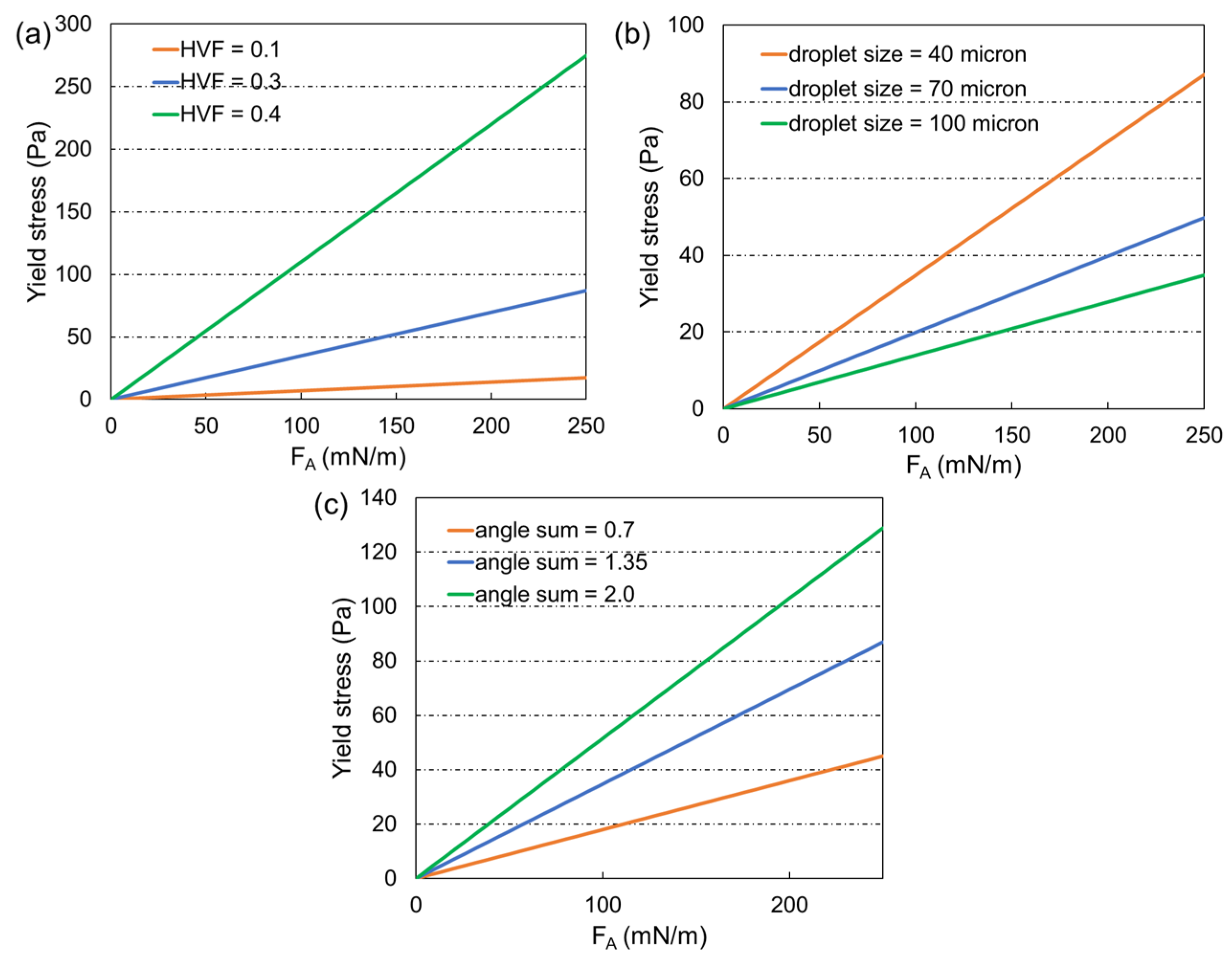
Figure 7 illustrates the sensitivity of the yield stress model to various system parameters, including droplet size d p , cohesive force F A , slurry hydrate particle volume fraction φ s l u r r y , and the summation of the critical number of load–bearing interparticle bonds i = 1 j c o s θ i . In Figure 7a, the relationship between yield stress and cohesive force or contact time is presented, demonstrating that an increase in cohesive force results in a higher yield stress, and the effect is more prominent at larger slurry hydrate volume fraction. Figure 7b presents how varying droplet sizes impact yield stress, indicating that smaller hydrate particles are associated with higher yield stress. Additionally, Figure 7c examines the influence of i = 1 j c o s θ i value on yield stress. The value, experimentally determined to range between 0.7 and 2.0 for nanoscale colloid particles, may not directly translate to hydrate systems at the microscale [53,57]. Despite this, the concept remains applicable due to the three–dimensional structure formed by hydrate particles and the existence of bonds between them that can break. Therefore, the term i = 1 j c o s θ i can be utilized as a fitting parameter in the model. Nevertheless, the experimental range of i = 1 j c o s θ i is used in Figure 7c to show its effect. A higher value represents the requirement to break more bonds to fluidize the system, resulting in a higher yield stress.
In the base case scenario, with a brief shut–in time resulting in a cohesive force of around 25 mN/m, the yield stress model predicts a yield stress of approximately 9 Pa. However, if the shut–in period extends to 24 h or longer, the cohesive force is anticipated to rise to about 200 to 250 mN/m. Under these conditions, the calculated yield stress is expected to fall between 70 and 80 Pa, qualitatively aligning with the experimental range summarized in Table A1.

4. Model Structure

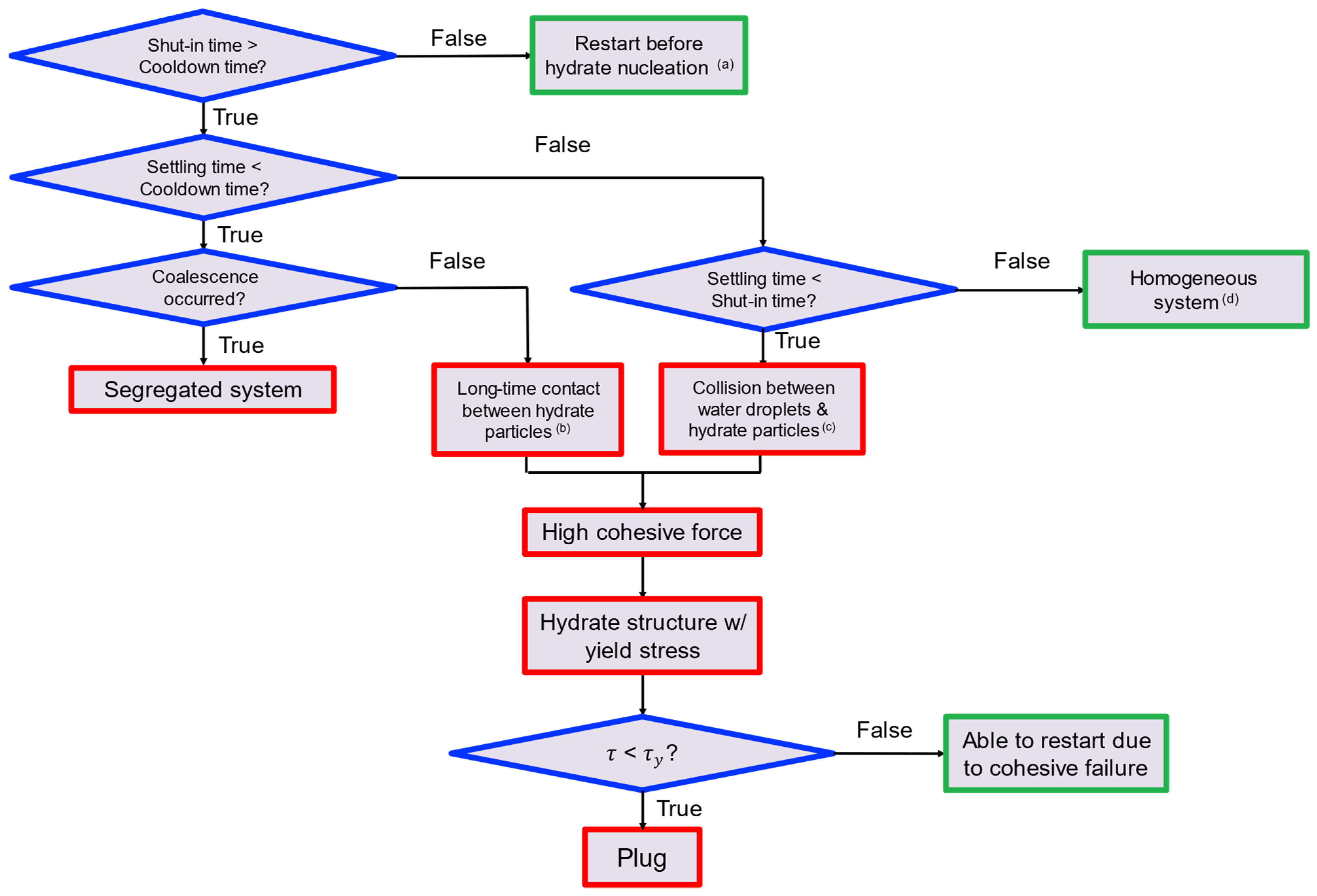
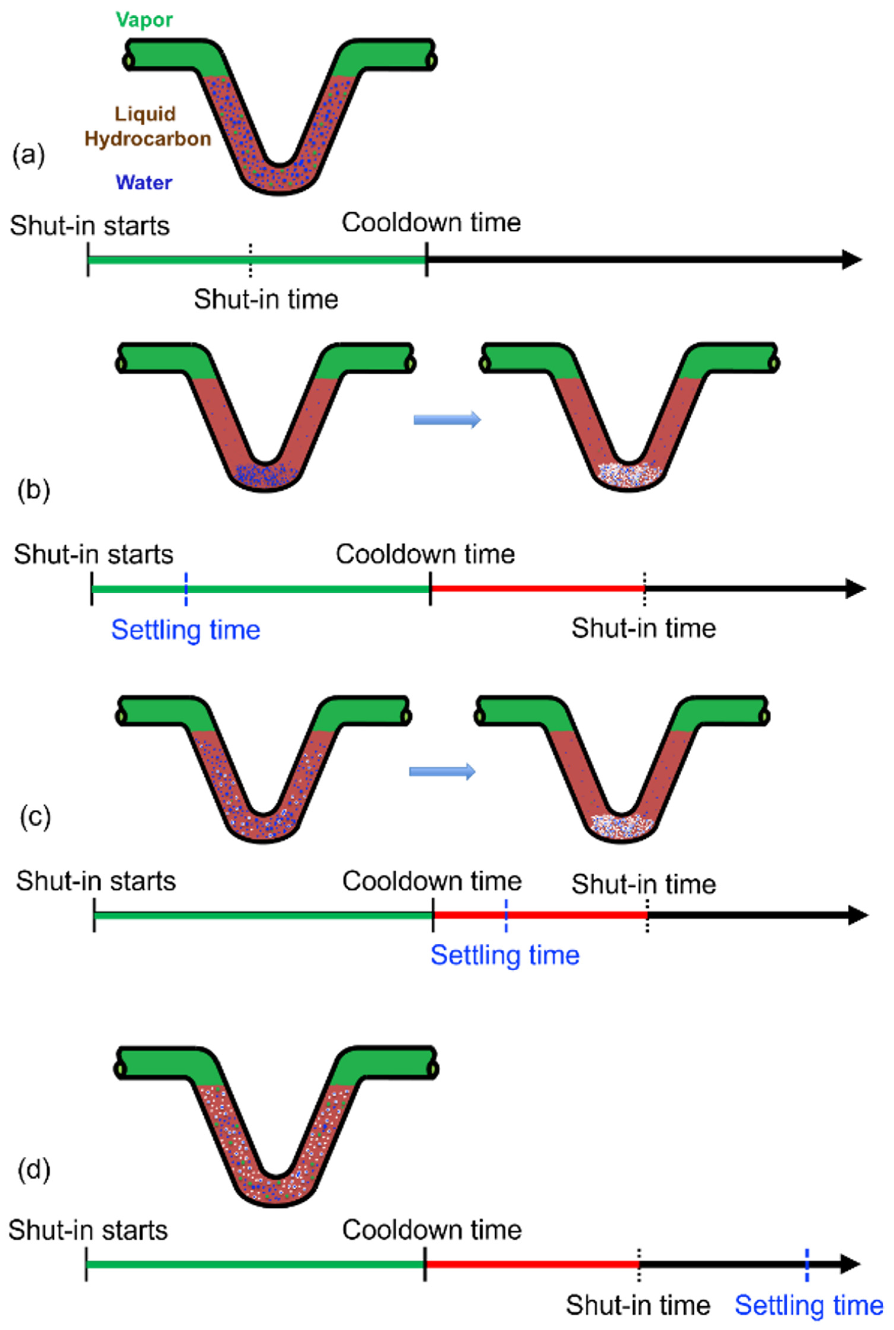
As a summary, Figure 8 and Figure 9 present a flow chart and corresponding time axes with conceptual pictures for each step of the fully dispersed transient model, respectively. Initially, the model assesses whether a well restart is planned before hydrate formation by comparing the shut–in time with the cooldown time. Shut–in time refers to the period during which a well is intentionally closed off, stopping the flow of hydrocarbons. The duration will vary from hours to days or months depending on whether the maintenance is minor or major. If the shut–in time is shorter than the cooldown time, hydrates will not form, and the simulation should proceed without considering hydrates. In cases where the shut–in time exceeds the cooldown time, the model takes hydrate interactions into account.
Next, the cooldown time is compared with the settling time to evaluate the potential formation of hydrate structures that exhibit yield stress. If the settling time is shorter than the cooldown time, water droplets will settle before hydrate formation occurs. The model does not consider coalescence scenarios, as they fall outside its scope and has been discussed in another work [19]. In the absence of coalescence, hydrates form around settled water droplets, resulting in a prolonged contact between hydrate particles and, consequently, a higher cohesive force.
In contrast, slower settling rates allows hydrate conversion during the settling process, leading to potential collisions between water droplets and hydrate particles. This scenario also results in a high cohesive force and yield stress. In extreme cases where water droplets scarcely settle, the formed hydrate particles remain separate, leading to a homogeneously dispersed system. In such instances, the model evaluates the viscosity of the hydrate suspension to determine the risk of hydrate blockage.
Lastly, the feasibility of well restart is determined by comparing the applied pressure gradient with the critical pressure gradient. This assessment is based on cohesive failure, as discussed in Section 2.4. The applied pressure gradient is calculated with the balance between the pressure drop across a pipeline segment with the stress exerted on the hydrate structure [59,60], as indicated in Equation (5), where P represents the differential pressure across the pipeline section before yielding, and L D is the length–to–diameter ratio of the pipeline.
τ = P 4 ( L D )

5. Model Validation with Large–Scale Flowloop Experiments

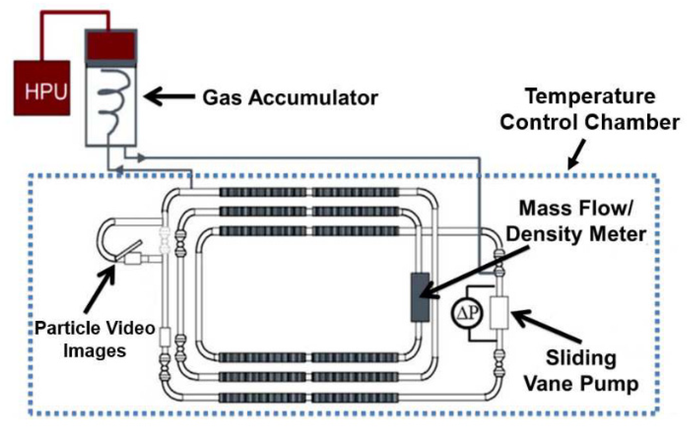
Large–scale flowloop experiments at different operating conditions were performed under transient operations to understand and validate restart mechanisms [61]. Figure 10 presents a schematic diagram of the flowloop setup. The flowloop has a testing section of 9.7 cm inner diameter and length of 96 m. A sliding vane pump is used to circulate the fluids at the desired mixture velocity. The flowloop is equipped with a Focused Beam Reflectance measurement (FBRM) tool and a Particle Visual Microscope (PVM) to characterize the water droplet or hydrate particle size during the flow or shut–in conditions, pressure transducers across the pump, temperature sensors, and a Coriolis flowmeter.
Flowloop experiments were conducted using methane, brine, and a sample of crude oil D, with API gravity of 33.21° and viscosity of 4.2 cP at 293.15 K. The interfacial tension between the crude oil and deionized water was measured to be 24.5 ± 1.4 mN/m. Brine containing 5 wt.% of synthetic salt was used for all the tests, and methane gas was used as the hydrate former. The tests were conducted at a constant pressure of 69 bar. In the transient test, the flowloop is firstly charged with liquids at 60 vol.% liquid holdup. This was then followed by cooling the temperature chamber to 3.3 °C for 24 h inside the hydrate equilibrium region. After 24 h shut–in period, the pump is restarted at different pump speed and run for another 12 h to study the restart mechanism. Finally, hydrates are dissociated by heating up the loop at constant pressure. The flowloop test matrix is summarized in Table 1.
Bottle test is performed to evaluate the emulsion stability during stagnant conditions to determine if the flowloop test is within the scope of the application of the fully dispersed system. A standardized bottle test procedure is used as presented in [32]. It can be seen from Figure 11 that water droplets will settle down, but not coalesce into free water layer, which confirms that the flowloop tests performed during the transient condition is within the fully dispersed system and can be applied to validate the conceptual model developed.
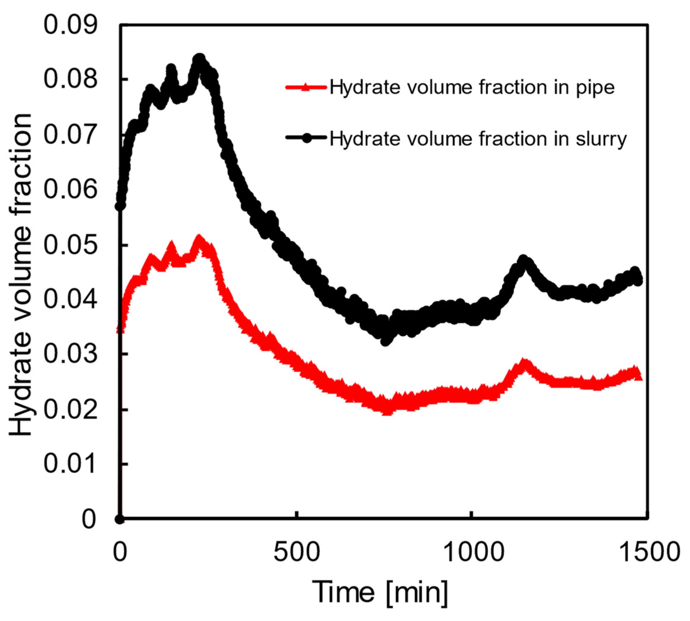
The hydrate formation in flowloop Test 5 during shut–in was calculated using the measured amount of gas consumed from the gas accumulator. As shown in Figure 12, it was found that, over the 24 h shut–in period, around 9 vol.% of hydrate in slurry, which corresponds to 5 vol.% of hydrate in the whole pipe, is formed. Therefore, step 3, as shown in the conceptual picture in Figure 2, is confirmed: there will be hydrate formation during shut–in, even though the amount is limited, primarily due to the limited access of hydrate former gas, and the mass–transfer limitation introduced by limited shear at the stagnant condition.
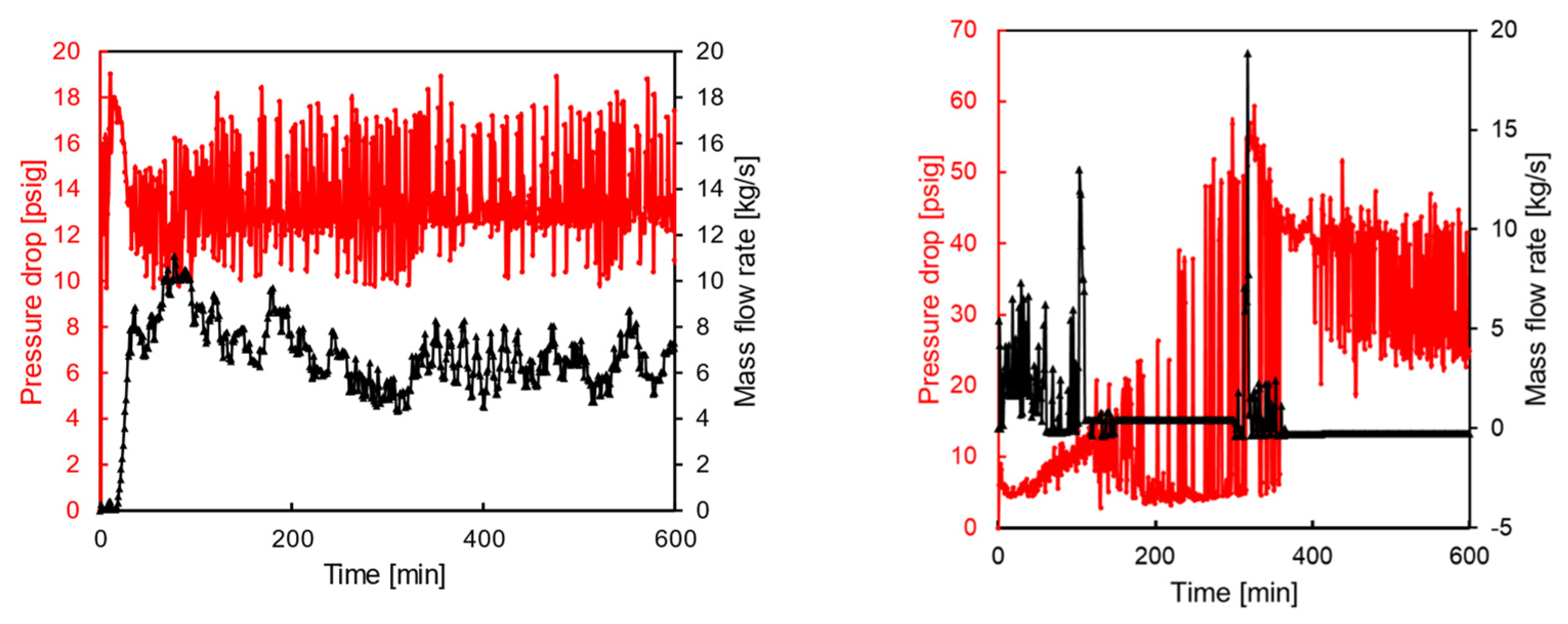
A plug in the flowloop is indicated by a limited mass flow rate and increases or large fluctuations in the pressure drop. The results of Test 3 and 4 are shown in Figure 13 to illustrate the no plug and plug conditions. Time zero is taken at the end of shut–in, corresponding to one minute before the pump is switched on. It can be seen in Figure 13 that, with 30% water cut and 1200 rpm pump speed, it takes less than 10 min for the system to reach the set mixture velocity, and the average pressure drop stays constant once the system is successfully restarted. It should be noted that the hydrate volume fraction in slurry is 20% at restart. On the contrary, at a 50% water cut and 350 rpm pump speed, there is significant fluctuation in the mass flow rate at the first 100 min of the restart, while after that period, the mass flow rate is stabilized at 0 kg/s. The pressure drop confirms that the system cannot be restarted successfully as the value becomes very high, which corresponds to a maximum relative pressure drop, defined as the ratio between the real–time pressure drop and the initial pressure drop, as high as 6.
The loop pressure drop was summarized to calculate the shear stress in the loop with Equation (5) and yield stress was calculated with Equation (2). According to the PVM images collected during shut–in, most of the droplets have a size of 20 μm, which was used in the calculation [61]. Additionally, previous work has shown that the cohesive force after 24 h contact between hydrate particles in crude oil D is around 50 mN/m [58]. The calculated shear and yield stress values are listed in Table 2. From the comparison between shear stress and yield stress, the plug information can be predicted, which is in agreement with the plug information observed from the flowloop experiments, as listed in Table 1.

6. Conclusions

The study of subsea flowline shut–in and restart processes, primarily related to gas hydrate formation and blockage, remains a relatively unexplored area in the field of multiphase flow and flow assurance. The transient operation stands out due to its unique characteristics, which differ significantly from the conventional understanding based on steady–state conditions. Transient operations also increase the likelihood of hydrate plug formation, highlighting the importance of this research area. This study presents a novel approach, reassessing previous steady–state conceptual pictures in light of transient conditions, to model fully dispersed systems. The new conceptual pictures are developed based on visual observations, the existing literature, and simulation studies of similar systems, with a focus on particle settling and the non–Newtonian behavior of fluids during shut–in and restart phases. The transient operations for large–scale flowloop study are also presented to validate that around 5 vol.% of the hydrate in the pipe is able to form during the shut–in stage, which contributes to the aggregate formation at the stagnant condition due to the interaction between water–hydrate and hydrate–hydrate. In addition to that, the concept of using a comparison between shear stress and yield stress to quantitatively determine the plug formation was validated.
To extend the applicability of this work, future research is being conducted to implement the model structure into the multiphase flow simulator, so that hydrate formation and plug determination during transient operation experiments can be evaluated with the developed tool. The coupled model will be applied to field–like conditions and verified using field data. Appropriate adjustments will be made to enhance the robustness and predictive capabilities of the models.

Author Contributions

Conceptualization, A.Q., L.E.Z. and C.A.K.; methodology, A.Q., N.A.I., J.G.D.-L. and A.A.A.M.; investigation, A.Q., N.A.I., J.G.D.-L., A.A.A.M., L.E.Z. and C.A.K.; writing—original draft preparation, A.Q.; writing—review and editing, N.A.I., J.G.D.-L., A.A.A.M., L.E.Z. and C.A.K.; supervision, L.E.Z. and C.A.K.; funding acquisition, C.A.K. All authors have read and agreed to the published version of the manuscript.

Funding

This research was funded by Colorado School of Mines Hydrate Consortium, which currently includes Chevron, ExxonMobil, Petrobras, Phillips 66, and TotalEnergies. Grant number 401019.

Data Availability Statement

The raw data supporting the conclusions of this article will be made available by the authors upon request.

Acknowledgments

The authors would like to acknowledge valuable inputs from the Colorado School of Mines Hydrate Consortium and helpful discussions with Luiz Dalla, Christopher Brock, Marshall Pickarts, Sriram Ravichandran, as well as all Hydrate busters from the Center for Hydrate Research, Colorado School of Mines.

Conflicts of Interest

The authors declare no conflicts of interest.

Appendix A

Table A1. Summary of yield stress measurements of hydrate systems.
ReferencesMethodsYield Stress MeasurementFluidHydrate FormerHydrate StructureYield Stress Investigation
Webb (2012) [46]Couette rheometerYield stress defined as the shear stress at which the shear rate increases rapidly.Water and West African crude oilMethaneStructure ⅠEffect of WVF at 2 h annealing time: no yield stress measured below 30% WVF, small yield stress from 3.7 to 6.8 Pa at 30% to 45% WVF, high yield stress greater than 3000 Pa at 50% WVF.
Effect of annealing time at 40% WVF: yield stress increased from 7 to 40.75 Pa from 2 to 48 h (increases with an annealing time up to 8 h and remains relatively unchanged.
Effect of 3.5 wt% NaCl at 50% WVF: brine slurry has much lower yield stress 37 Pa compared with slurry formed using DI water.
Webb (2013) [47]Couette rheometerYield stress defined as the shear stress at which the shear rate increases rapidly.Water, dodecane, and aerosol dioctyl sodium sulfosuccinate (AOT) surfactantMethaneStructure ⅠEffect of WVF at 0 °C, 1500 psig P0 and 100 s−1 shear rate: yield stress of 5% WVF: 1 Pa; 10% WVF: 2 Pa; 25% WVF: 5 Pa; 30% WVF: 20 Pa.
Effect of temperature at 30% WVF, 1500 psig P0 and 100 s−1 shear rate: yield stress of 2 °C: 4 Pa.
Effect of WVF: yield stress at 30% WVF: 3 Pa; 20% WVF: 1 Pa.
Zylyftari, (2013) [49]Strain–controlled Couette rheometerYield stress defined as the value of the stress plateau at a low shear rate.Water, oil mixture of light mineral oil and Halocarbon 27, Span 80 surfactant and cyclopentane, and dissolved NaClCyclopentaneStructure ⅡEffect of salt concentration: yield stress of initial salt concentration 0.0 wt.%: 38 Pa; 3.4 wt.%: 145 Pa; 5.0 wt.%: 104 Pa; 7.5 wt.%: 90 Pa; 10.0 wt.%: 90 Pa; 12.5 wt.%: 0.3 Pa; 15.0 wt.%: 0.2 Pa.
Webb (2014) [50]Couette rheometerYield stress defined as the shear stress at which the shear rate increases rapidly.Water, mineral oil 70T, Span 80 surfactant, and dioctyl sodium sulfosuccinate (AOT) surfactantMethaneStructure ⅠEffect of WVF at 0 °C and 1500 psig P0: yield stress of 10% WVF: 3 Pa; 20% WVF: 11 Pa; 30% WVF: 18 Pa; 40% WVF: 21 Pa.
Effect of temperature at 30% WVF and 1500 psig P0: yield stress of 2 °C: 43 Pa; 4 °C: 110 Pa; 6 °C: 30 Pa.
Effect of P0 at 30% WVF and 0 °C: yield stress at 750 psig P0: 380 Pa; 1000 psig P0: 75 Pa; 1250 psig P0: 65 Pa.
Zylyftari, (2015) [51]Four–bladed vane rheometerYield stress of the final structure measured with oscillatory stress ramp method without aging.
Yield stress defined as the maximum value in elastic stress.
Water, oil mixture of light mineral oil and Halocarbon 27, Span 80 surfactant and cyclopentane, and dissolved NaClCyclopentaneStructure ⅡEffect of salt concentration: average yield stress of initial salt concentration 0.0 wt.%: 1250 Pa; 3.4 wt.%: 1960 Pa; 5.0 wt.%: 1620 Pa; 7.5 wt.%: 1700 Pa; 10.0 wt.%: 24 Pa; 12.5 wt.%: 0.14 Pa; 15.0 wt.%: 0.17 Pa.
Ahuja (2015) [52]Stress–controlled Couette and four–bladed vane rheometerYield stress measured with 1. Oscillatory stress ramp method: Yield stress taken at shape decrease in storage and loss moduli over amplitude of oscillatory stress 2. Elastic stress maxima method: Yield stress defined as maximum elastic stressWater, oil mixture of light mineral oil and Halocarbon 27, Span 80 surfactant, and cyclopentaneCyclopentaneStructure ⅡEffect of WVF: increasing yield stress with increasing water volume fraction above 15% WVF.
Effect of shut–in time: increasing yield stress with increasing shut–in time for all water fractions.
Effect of different rheological methods for yield stress measurement: in good agreement.
Alejandro (2019) [53]Four–bladed vane rheometerYield stress measured with ramping shear stress from 0.01 to 2500 Pa.
Yield stress defined as the shear stress at which the shear rate increases rapidly.
Water, oil mixture of mineral oil 70T, NaCl, and hydrate dispersants (HD) A–EMethaneStructure ⅠEffect of shut–in time and HD dosage: at 0.25 vol.% HD_A: yield stress of 0 h shut–in time: 55 Pa; 4 h: 2280 Pa; 8 h: 495 Pa; at 0.5 vol.% HD_A: 0 h: 45 Pa; 4 h: 60 Pa; 8 h: 75 Pa; at 1 vol.% HD_A: 0 h: 7 Pa; 4 h: 10 Pa; 8 h: 11 Pa; at 2 vol.% HD_A: 0 h: 9 Pa; 4 h:8 Pa; 8 h: 12 Pa. Effect of different HD type: at 2 vol.% HD_C: yield stress of 0 h shut–in time: 18 Pa; at 1 vol.% HD_D: 8 Pa; at 2 vol.% HD_E: 27 Pa; at 5 vol.% HD_E: 15 Pa. Effect of WVF: yield stress of 2 vol.% HD_A and 80% WC: at 0 h shut–in time: 27 Pa; 4 h: 22 Pa; 8 h: 26 Pa.
Qin (2020) [54]Four–bladed vane rheometerYield stress measured with ramping shear stress from 0.1 to 300 Pa over 1080 s.
Yield stress defined as the shear stress at which the shear rate increases rapidly.
Water, crude oil, and industrial AAMethaneStructure ⅠEffect of WVF at 5 °C and 1500 psig P0 without AA: yield stress of 5% WVF: 2.4 Pa; 10% WVF: 11 Pa; 20% WVF: 19 Pa; 30% WVF: 24.5 Pa.
Effect of AA at 5 °C and 1500 psig P0 with AA: yield stress of 10% WVF: 3.7 Pa; 20% WVF: 4.0 Pa; 30% WVF: 4.5 Pa.
Liu (2020) [55]Couette rheometerYield stress measured with ramping shear stress from 1 to 1000 Pa.
Yield stress defined as the shear stress at which the shear rate increases rapidly.
Water, n–decane, and Span 80 and Tween 80 as surfactants (50 vol.% water cut)MethaneStructure ⅠEffect of annealing time: for 5 wt.% surfactant: yield stress of 5 min shut–in: 37 Pa; 10 min: 38 Pa; 20 min: 46 Pa; 40 min: 52 Pa; 80 min: 63 Pa; 160 min: 82 Pa; 320 min: 116 Pa; 640 min: 150 Pa; 1280 min: 217 Pa.
For 10 wt.% surfactant: yield stress of 5 min shut–in: 25 Pa; 10 min: 29 Pa; 20 min: 33 Pa; 40 min: 40 Pa; 80 min: 45 Pa; 160 min: 59 Pa; 320 min: 76 Pa; 640 min: 88 Pa; 1280 min: 184 Pa.
Effect of surfactant concentration: for 5 min shut–in: yield stress of no surfactant: exceed 1000 Pa; 3 wt.% surfactant: 615 Pa; 5 wt.% surfactant: 37 Pa; 10 wt.% surfactant: 25 Pa.
Sakurai (2021) [56]FlowloopMeasure critical stress required for flow restart on a straight, horizontal 1.35 m pipe run with the dP transducer affixed to a 0.85 m length of pipe.100% waterMethaneStructure ⅠEffect of HVF: yield stress of 0–20 vol.% HVF: 0–15 Pa.
Effect of restart operation (slow linear or quick exponential): slow linear: hydrate blockage; quick exponential: no hydrate blockage.
Effect of shut–in time (3 min or 8 h): 3 min shut–in: 0–10 Pa; 8 h shut–in: 0–14 Pa.
Liu (2022) [48]Couette rheometerYield stress measured with ramping shear stress from 1 to 1000 Pa.
Yield stress defined as the shear stress at which the shear rate increases rapidly.
Water, n–decane, Span 80 and Tween 80 as surfactants (50 vol.% water cut), and dissolved NaClMethaneStructure ⅠEffect of annealing time and salinity: for 1 wt.% salinity and 53.2% water conversion fraction: yield stress of 5 min shut–in: 25 Pa; 10 min: 33 Pa; 20 min: 47 Pa; 40 min: 56 Pa; 80 min: 57 Pa; 160 min: 80 Pa; 320 min: 230 Pa; 640 min: 258 Pa; 1280 min: 270 Pa.
For 5 wt.% salinity and 43.9% water conversion fraction: yield stress of 5 min shut–in: 12 Pa; 10 min: 15 Pa; 20 min: 19 Pa; 40 min: 20 Pa; 80 min: 21 Pa; 160 min: 16 Pa; 320 min: 19 Pa; 640 min: 27 Pa; 1280 min: 37 Pa.

References

  1. Sloan, E.D., Jr.; Koh, C.A. Clathrate Hydrates of Natural Gases; CRC Press: Boca Raton, FL, USA, 2007. [Google Scholar]
  2. Davy, H. VIII. On a Combination of Oxymuriatic Gas and Oxygene Gas. R. Soc. 1811, 101, 155–162. [Google Scholar]
  3. Faraday, M. XIV. On Fluid Chlorine. R. Soc. 1823, 14, 160–165. [Google Scholar]
  4. Hammerschmidt, E.G. Formation of Gas Hydrates in Natural Gas Transmission Lines. Ind. Eng. Chem. 1934, 26, 851–855. [Google Scholar] [CrossRef]
  5. Sangwai, J.; Dandekar, A. Practical Aspects of Flow Assuracne in the Petroleum Industry; CRC Press Taylor & Francis Group: Boca Raton, FL, USA, 2023. [Google Scholar]
  6. Chakrabarti, S.K. Handbook of Offshore Engineering; Elsevier: Amsterdam, The Netherlands, 2005; pp. 15–200. [Google Scholar] [CrossRef]
  7. Mokwenye, P.O. Evaluation of Gas Hydrate in Gas Pipeline Transportation. Master’s Thesis, Universit of North Dakota, Grand Forks, ND, USA, 2020. [Google Scholar]
  8. Bimuratkyzy, K.; Sagindykov, B. The Review of Flow Assurance Solutions with Respect to Wax and Asphaltene. Braz. J. Pet. Gas 2016, 10, 119–134. [Google Scholar] [CrossRef]
  9. Mullins, O.C. The Asphaltenes. Annu. Rev. Anal. Chem. 2011, 4, 393–418. [Google Scholar] [CrossRef] [PubMed]
  10. Jordan, M.M.; Mariow, D.; Johnson, T.L.; Johnston, C. The Evaluation of Enhanced (Carbonate/Sulfate) Scale-Dissolver Treatments for near-Wellbore Stimulation in Subsea Production Wells, Gulf of Mexico. In Proceedings of the SPE International Oilfield Scale Symposium, Aberdeen, UK, 31 May–1 June 2006; pp. 24–40. [Google Scholar] [CrossRef]
  11. Perumal, K.E. Corrosion Risk Analysis, Risk Based Inspection and a Case Study Concerning a Condensate Pipeline. Procedia Eng. 2014, 86, 597–605. [Google Scholar] [CrossRef]
  12. Kokal, S. Crude-Oil Emulsions: A State-of-the-Art Review. SPE Prod. Facil. 2005, 20, 5–12. [Google Scholar] [CrossRef]
  13. Gharaibah, E.; Zhang, Y. Flow Assurance Aspects and Optimization of Subsea Choke Valve Sand Management and Erosion. In Proceedings of the OTC Brasil, Rio de Janeiro, Brazil, 27–29 October 2015; pp. 1656–1665. [Google Scholar] [CrossRef]
  14. Vatamanu, J.; Kusalik, P.G. Molecular Insights into the Heterogeneous Crystal Growth of SImethane Hydrate. J. Phys. Chem. B 2006, 110, 15896–15904. [Google Scholar] [CrossRef]
  15. Cochran, S. Hydrate Control and Remediation Best Practices in Deepwater Oil Developments. In Proceedings of the Offshore Technology Conference, Houston, TX, USA, 5–8 May 2003; pp. 1696–1709. [Google Scholar] [CrossRef]
  16. Cardoso, C.A.B.R.; Gonçalves, M.A.L.; Camargo, R.M.T. Design Options for Avoiding Hydrates in Deep Offshore Production. J. Chem. Eng. Data 2015, 60, 330–335. [Google Scholar] [CrossRef]
  17. Volk, M.; Delle-Case, E.; Estanga, D. Risk-Based Restarts of Untreated Subsea Oil and Gas Flowlines in the GoM; The University of Tulsa: Tulsa, OK, USA, 2007. [Google Scholar]
  18. Turner, D.J. Clathrate Hydrate Formation in Water-in-Oil Dispersions. Ph.D. Thesis, Colorado School of Mines, Golden, CO, USA, 2005. [Google Scholar]
  19. Pickarts, M.A.; Ravichandran, S.; Ismail, N.A.; Stoner, H.M.; Delgado-Linares, J.; Sloan, E.D.; Koh, C.A. Perspective on the Oil-Dominated Gas Hydrate Plugging Conceptual Picture as Applied to Transient Shut-In/Restart. Fuel 2022, 324, 124606. [Google Scholar] [CrossRef]
  20. Zerpa, L.E.; Salager, J.L.; Koh, C.A.; Sloan, E.D.; Sum, A.K. Surface Chemistry and Gas Hydrates in Flow Assurance. Ind. Eng. Chem. Res. 2011, 50, 188–197. [Google Scholar] [CrossRef]
  21. Malkin, A.Y.; Mironova, M.V.; Ilyin, S.O. Flow of Heavy Crude Oil-in-Water Emulsions in Long Capillaries Simulating Pipelines. J. Pet. Sci. Eng. 2017, 157, 117–123. [Google Scholar] [CrossRef]
  22. Wang, Y. The Development and Application of Hydrate Formation, Transportation and Bedding Models in Liquid-Dominated Systems. Ph.D. Thesis, Colorado School of Mines, Golden, CO, USA, 2019. [Google Scholar]
  23. Bhatnagar, G.; Gao, S. Gas Hydrate Management. In Flow Assurance; Gulf Professional Publishing: Cambridge, MA, USA, 2022; ISBN 9780128220108. [Google Scholar]
  24. Qian, Y.; Xu, J.; Yuan, H.; Peng, C.; Zhou, F. Study on the Hydrocyclonic Separation of Natural Gas Hydrate Slurries Combined with the Solution of Particles’ Settling Equation. Ind. Eng. Chem. Res. 2022, 61, 14637–14648. [Google Scholar] [CrossRef]
  25. Li, Q.; Shirazi, S.A.; McLaury, B.S.; Kouba, G.; Song, S. Measurements and Modeling of Particle Sedimentation Rate and Settling Velocity in a Vertical Pipe. In Proceedings of the ASME 2005 Fluids Engineering Division Summer Meeting, Houston, TX, USA, 19–23 June 2005. [Google Scholar]
  26. Navaneetha Kannan, S.; Daraboina, N.; Venkatesan, R.; Sarica, C. Settling and Re-Entrainment of Wax Particles in near-Gelling Systems. AIChE J. 2018, 64, 765–772. [Google Scholar] [CrossRef]
  27. Golchha, A.; Sarica, C.; Venkatesan, R. Settling of Wax Particles in Near-Gelling Systems under Quiescent Conditions. In Proceedings of the Offshore Technology Conference, Houston, TX, USA, 4–7 May 2015; pp. 83–99. [Google Scholar] [CrossRef]
  28. Petrosky, G.E.; Farshad, F.F. Viscosity Correlations for Gulf of Mexico Crude Oils. In Proceedings of the SPE Production Operations Symposium, Oklahoma City, OK, USA, 2–4 April 1995; pp. 249–258. [Google Scholar] [CrossRef]
  29. Qin, Y.; Aman, Z.M.; Pickering, P.F.; Johns, M.L.; May, E.F. High Pressure Rheological Measurements of Gas Hydrate-in-Oil Slurries. J. Nonnewton. Fluid Mech. 2017, 248, 40–49. [Google Scholar] [CrossRef]
  30. Guo, B.; Lyons, W.C.; Ghalambor, A. Petroleum Production Engineering a Computer Assisted Approach; Gulf Professional Publishing: Woburn, MA, USA, 2017; ISBN 9780128093740. [Google Scholar]
  31. Kurup, A.S.; Hernandez, O.; Idstein, T.; Zamora, C.A.; Greenly, L.; Anderson, J. Pushing Conventional Boundaries of Hydrate Management in a Dry Tree Facility. In Proceedings of the Offshore Technology Conference, Houston, TX, USA, 1–4 May 2017; pp. 1415–1427. [Google Scholar] [CrossRef]
  32. Salmin, D.C.; Delgado-Linares, J.G.; Wu, D.T.; Zerpa, L.E.; Koh, C.A. Hydrate Agglomeration in Crude Oil Systems in Which the Asphaltene Aggregation State Is Artificially Modified. SPE J. 2021, 26, 1189–1199. [Google Scholar] [CrossRef]
  33. Dykhno, L.A.; Jayawardena, S.S.; Schoppa, W. Blowdown Feasibility for Downhill Flowlines. In Proceedings of the Offshore Technology Conference, Houston, TX, USA, 5–8 May 2003; pp. 1710–1717. [Google Scholar] [CrossRef]
  34. Høiland, S.; Askvik, K.M.; Fotland, P.; Alagic, E.; Barth, T.; Fadnes, F. Wettability of Freon Hydrates in Crude Oil/Brine Emulsions. J. Colloid Interface Sci. 2005, 287, 217–225. [Google Scholar] [CrossRef]
  35. Fidel-Dufour, A.; Gruy, F.; Herri, J.M. Rheology of Methane Hydrate Slurries during Their Crystallization in a Water in Dodecane Emulsion under Flowing. Chem. Eng. Sci. 2006, 61, 505–515. [Google Scholar] [CrossRef]
  36. Colombel, E.; Gateau, P.; Barré, L.; Gruy, F.; Palermo, T. Discussion Sur Les Mécanismes d’agglomération Entre Particules d’hydrate Dans Les Émulsions Eau Dans Huile. Oil Gas Sci. Technol. 2009, 64, 629–636. [Google Scholar] [CrossRef]
  37. Ismail, N.A.; Delgado-Linares, J.G.; Koh, C.A. High Pressure Micromechanical Force Method to Assess the Non-Plugging Potential of Crude Oils and the Detection of Asphaltene-Hydrate Mixed Agglomerates. Fuel 2023, 335, 126871. [Google Scholar] [CrossRef]
  38. Song, J.H.; Couzis, A.; Lee, J.W. Direct Measurements of Contact Force between Clathrate Hydrates and Water. Langmuir 2010, 26, 9187–9190. [Google Scholar] [CrossRef] [PubMed]
  39. Song, J.H.; Couzis, A.; Lee, J.W. Investigation of Macroscopic Interfacial Dynamics between Clathrate Hydrates and Surfactant Solutions. Langmuir 2010, 26, 18119–18124. [Google Scholar] [CrossRef] [PubMed]
  40. Kokal, S.L.; Sayegh, S.G. Asphaltenes: The Cholesterol of Petroleum. Proc. Middle East Oil Show 1995, 1, 169–181. [Google Scholar] [CrossRef]
  41. Schramm, L.L. Emulsions, Foams, and Suspensions; Wiley-VCH: Weinheim, Germany, 2005; ISBN 9783527307432. [Google Scholar]
  42. Bui, T.; Phan, A.; Monteiro, D.; Lan, Q.; Ceglio, M.; Acosta, E.; Krishnamurthy, P.; Striolo, A. Evidence of Structure-Performance Relation for Surfactants Used as Antiagglomerants for Hydrate Management. Langmuir 2017, 33, 2263–2274. [Google Scholar] [CrossRef] [PubMed]
  43. Lo, C.; Zhang, J.S.; Couzis, A.; Somasundaran, P.; Lee, J.W. Adsorption of Cationic and Anionic Surfactants on Cyclopentane Hydrates. J. Phys. Chem. C 2010, 114, 13385–13389. [Google Scholar] [CrossRef]
  44. Phan, A.; Bui, T.; Acosta, E.; Krishnamurthy, P.; Striolo, A. Molecular Mechanisms Responsible for Hydrate Anti-Agglomerant Performance. Phys. Chem. Chem. Phys. 2016, 18, 24859–24871. [Google Scholar] [CrossRef] [PubMed]
  45. Aman, Z.M. Interfacial Phenomena of Cyclopentane Hydrate. Ph.D. Thesis, Colorado School of Mines, Golden, CO, USA, 2012. [Google Scholar]
  46. Webb, E.B.; Rensing, P.J.; Koh, C.A.; Sloan, E.D.; Sum, A.K.; Liberatore, M.W. High-Pressure Rheology of Hydrate Slurries Formed from Water-in-Oil Emulsions. Energy Fuels 2012, 26, 3504–3509. [Google Scholar] [CrossRef]
  47. Webb, E.B.; Koh, C.A.; Liberatore, M.W. Rheological Properties of Methane Hydrate Slurries Formed from AOT + Water + Oil Microemulsions. Langmuir 2013, 29, 10997–11004. [Google Scholar] [CrossRef]
  48. Liu, Z.; Wang, J.; Liu, W.; Li, Y.; Lang, C.; Zhang, M.; Song, Y. Effect of Brine Salinity on the Rheological Properties of Hydrate-in-Oil Slurries. J. Pet. Sci. Eng. 2022, 208, 109756. [Google Scholar] [CrossRef]
  49. Zylyftari, G.; Lee, J.W.; Morris, J.F. Salt Effects on Thermodynamic and Rheological Properties of Hydrate Forming Emulsions. Chem. Eng. Sci. 2013, 95, 148–160. [Google Scholar] [CrossRef]
  50. Webb, E.B.; Koh, C.A.; Liberatore, M.W. High Pressure Rheology of Hydrate Slurries Formed from Water-in-Mineral Oil Emulsions. Ind. Eng. Chem. Res. 2014, 53, 6998–7007. [Google Scholar] [CrossRef]
  51. Zylyftari, G.; Ahuja, A.; Morris, J.F. Modeling Oilfield Emulsions: Comparison of Cyclopentane Hydrate and Ice. Energy Fuels 2015, 29, 6286–6295. [Google Scholar] [CrossRef]
  52. Ahuja, A.; Zylyftari, G.; Morris, J.F. Yield Stress Measurements of Cyclopentane Hydrate Slurry. J. Nonnewton. Fluid Mech. 2015, 220, 116–125. [Google Scholar] [CrossRef]
  53. Dapena, J.A. On the Kinetic Arrest of Hydrate Slurries. Ph.D. Thesis, Colorado School of Mines, Golden, CO, USA, 2019. [Google Scholar]
  54. Qin, Y.; Pickering, P.F.; Johns, M.L.; May, E.F.; Aman, Z.M. Rheological Method to Describe Metastable Hydrate-in-Oil Slurries. Energy Fuels 2020, 34, 7955–7964. [Google Scholar] [CrossRef]
  55. Liu, Z.; Song, Y.; Liu, W.; Liu, R.; Lang, C.; Li, Y. Rheology of Methane Hydrate Slurries Formed from Water-in-Oil Emulsion with Different Surfactants Concentrations. Fuel 2020, 275, 117961. [Google Scholar] [CrossRef]
  56. Sakurai, S.; Hoskin, B.; Choi, J.; Norris, B.W.E.; May, E.F.; Johns, M.L.; Aman, Z.M. Behavior of Methane Hydrate-in-Water Slurries from Shut-in to Flow Restart. Energy Fuels 2021, 35, 13086–13097. [Google Scholar] [CrossRef]
  57. Studart, A.R.; Amstad, E.; Gauckler, L.J. Yielding of Weakly Attractive Nanoparticle Networks. Soft Matter 2011, 7, 6408–6412. [Google Scholar] [CrossRef]
  58. Hu, S. Interfacial Properties of CH4/C2H6 Gas Hydrate Particles with Chemical Additives. Ph.D. Thesis, Colorado School of Mines, Golden, CO, USA, 2019. [Google Scholar]
  59. Lee, H.S.; Singh, P.; Thomason, W.H.; Fogler, H.S. Waxy Oil Gel Breaking Mechanisms: Adhesive versus Cohesive Failure. Energy Fuels 2008, 22, 480–487. [Google Scholar] [CrossRef]
  60. Ekweribe, C.; Civan, F.; Lee, H.S.; Singh, P. Effect of System Pressure on Restart Conditions of Subsea Pipelines. In Proceedings of the SPE Annual Technical Conference and Exhibition, Denver, CO, USA, 21–24 September 2008; pp. 1754–1775. [Google Scholar] [CrossRef]
  61. Srivastava, V. Quantitative Risk Modeling of Hydrate Bedding Using Mechanistic, Statistical, and Artifical Neural Network Frameworks. Ph.D. thesis, Colorado School of Mines, Golden, CO, USA, 2018. [Google Scholar]
Figure 1. Original steady–state gas hydrate plugging conceptual picture for oil–dominated systems. Figure modified from [18] with input from J. Abrahamson.
Fuels 05 00017 g001
Figure 2. Overall conceptual pictures of gas hydrate formation in a hydrocarbon with surface–active components during transient shut–in/restart operations. Step 1: formation of an emulsion during steady–state continuous production, persisting at the start of shut–in. Step 2(a): hydrate formation during prolonged shut–in. Step 3(a): settling causes hydrate particles to collide with water droplets. Step 2(b): as an alternative, water droplets settle at the bottom of the pipe first. Step 3(b): hydrate forms outside the water droplets. Step 4: initial compression of the hydrate phase upon restart, prior to flow resumption. Step 5(a): disruption of hydrate structure due to cohesive failure if shear stress exceeds yield stress. Step 5(b): system plugs at restart if shear stress cannot exceed yield stress.
Fuels 05 00017 g002
Figure 3. Surface plot showing the relationship between particle diameter, fluid viscosity, and settling velocity with fluid viscosity in the range from 0 to 20 cP (left) and fluid viscosity in the range from 20 to 100 cP (right), with crude oil fixed at 0.8 g/cm3 (equivalent to API gravity of 45.3°). The assumption is that the particle volumetric concentration is 30% and particles are of spherical shape ( φ s = 1 ).
Fuels 05 00017 g003
Figure 4. Bottle test comparisons: heavy Crude A with 30 and 50% water cuts (left), showing a homogeneous water–in–oil mixture after 24 h, and lighter Crude B (right), exhibiting water settling. In both tests, no separate free water phase is observed.
Fuels 05 00017 g004
Figure 5. Rocking cell test of the Crude B suggests hydrate formation during a long period of shut–in.
Fuels 05 00017 g005
Figure 6. (a) Water droplet conversion upon contact with the CH4/C2H6 hydrate particle immersed in MO 70T in HP–MMF at the subcooling temperature of 1.7 °C and pressure of 500 psig. Top: CH4/C2H6 hydrate particle. Bottom: water droplet. At t = 60 s, the water droplet does not coalesce into a hydrate particle, but leads to the incomplete conversion of the water droplet into hydrate. (b) Water droplet conversion upon contact with cyclopentane hydrate particle in LP–MMF at subcooling temperature of 1.7 °C. Top: water droplet. Bottom: cyclopentane hydrate particle, where both were immersed in a 0.02 vol.% concentration of non–plugging oil Crude C.
Fuels 05 00017 g006
Figure 7. Sensitivity analysis of the yield stress model as function of hydrate particle cohesion force in terms of (a) the hydrate volume fraction (HVF), (b) the droplet size, and (c) the summation of the angle term used as a fitting parameter, with a baseline of the slurry hydrate volume fraction (HVF) of 30 vol.%, fractal dimension of 2.5, droplet size of 40 μm, and summation of angle term of 1.35.
Fuels 05 00017 g007
Figure 8. Hydrate fully dispersed transient model flow diagram. The corresponding time axis with conceptual pictures of four main steps (a), (b), (c), and (d) are illustrated in Figure 9.
Fuels 05 00017 g008
Figure 9. The time axes and conceptual pictures corresponding to the four main steps shown in the model flow diagram: (a) restart before hydrate nucleation, (b) long time contact between hydrate particles, (c) collision between water droplets and hydrate particles, and (d) homogeneously dispersed system.
Fuels 05 00017 g009
Figure 10. Schematic diagram of the large–scale flowloop. Figure modified from [61].
Fuels 05 00017 g010
Figure 11. Bottle test results with 30 and 50 vol.% water cut at 24 h, which indicate no water coalescence or free water layer will show up during stagnant condition.
Fuels 05 00017 g011
Figure 12. Hydrate volume fraction in pipe (red) and slurry (black) of Test 5.
Fuels 05 00017 g012
Figure 13. Pressure drop (red) and mass flow rate (black) of Test 3 (left) and Test 4 (right).
Fuels 05 00017 g013
Table 1. Summary of flowloop test matrix.
Experiment
No.
Water Cut
[vol.%]
Pump Speed
[rpm]
Mixture Velocity
[m/s]
Plug Observed
1305001.13No
2307501.74No
33012002.87No
4503500.73Yes
5507501.74Yes
65012002.87No
Table 2. Summary of plug determination.
Experiment
No.
Loop Pressure Drop
at Restart
[psig]
Shear Stress
[Pa]
Yield Stress
[Pa]
Plug Based
on Comparison
110.143.38.4No
211.145.116.8No
31958.96.9No
48.240.0185.8Yes
511.345.4140.2Yes
627.173.060.0No
Disclaimer/Publisher’s Note: The statements, opinions and data contained in all publications are solely those of the individual author(s) and contributor(s) and not of MDPI and/or the editor(s). MDPI and/or the editor(s) disclaim responsibility for any injury to people or property resulting from any ideas, methods, instructions or products referred to in the content.