
Green Fleet: A Prototype Biogas and Hydrogen Refueling Management System for Private Fleet Stations

 , and
, and 
Abstract
1. Introduction
- To show the needs and peculiarities derived from a completely new and innovative green fuel management system, which is not available in the market to date. This paper will also detail the main differences from existing information systems used to manage refueling stations for conventional Liquid Petroleum Products (LPPs), i.e., diesel and gasoline. Such systems are not suitable nor prepared for the complexity and diverse data managed by new green fuel technologies. Section 2 below lists arguments for not using the legacy technology still marketed and describes the main differences between conventional and biogas/hydrogen systems.
- To describe the design and development process of an information system prototype offering solutions to these needs and peculiarities. The prototype will provide an opportunity to unveil the risks and improvement prospects associated with this type of system. Knowledge of devices commonly installed in these facilities—dispensers and sensors—is essential for this prototype. Their standard communication protocols also became a key issue. Current information systems architecture approaches were considered for this project as well. Concepts such as Internet of Things (IoT) or fog computing [5] are widely used in this prototype.
2. Main Differences between LPP and Biogas/Hydrogen Private Refueling Facilities
- Biogas installations, and particularly H2 sites, must be monitored more carefully and accurately. There are a large number of parameters to watch in order to ensure safe and productive facilities. Biogas and H2 fuels are both gases under normal pressure and temperature conditions, which need to be compressed for storage in pressurized tanks or bottle racks. Additionally, hydrogen must be extremely cooled before delivery to any vehicle tank [6]. Pressure and temperature monitoring at these facilities are critical factors not required for diesel stations at all.
- For most LPP facilities, refueling is measured through an analogue input from a square wave pulse generator linked to a liquid flow meter. This equipment is not available for current biogas or hydrogen dispensers. Thus, delivery data must be obtained from the dispenser itself through a protocol-based communication system.
- The tank level system for measuring biogas or hydrogen stocks in pressurized containers is radically distinct from those used for LPP fuels and thus must be monitored differently [7].
- Green gas dispenser control differs completely from standard EV rechargers.
- Monitoring systems for green gas sites are much more complex as data parameters are collected from very diverse control devices.
- As a result, Single Board Computing (SBC) is the only available solution to manage this type of facility. SBC technology is not used for EV stations.
- During the prototype phase, new requirements were discovered, especially related to green gas traceability management and legal compliance. Such requirements do not exist in the EV recharging market.
3. Materials and Methods
3.1. Technologies
- Proven effectiveness in solving the needs for which they were created.
- The adequate balance between novelty and maturity. One of the designer’s most demanding tasks is to select technologies that are innovative enough to add value to the project but mature enough to be stable and not end up as a fleeting trend.
- Widespread enough to find expert developers without too much difficulty.
- Inexpensive enough to keep the project and final product costs low. Most of the technologies used are publicly available or open source.
- Reputation: all technologies are commonly accepted by the developer’s community and have been successfully used in large projects.
- Affinity with the activity sector: some of the selected technologies have a particularly relevant presence in the sector targeted by the project, as they solve specific issues.
- Alignment with the development team. Among the technologies meeting the above criteria, there is a tendency to select those where the design or the development team have a certain affinity or experience. This ensures greater stability of the final product and shorter development cycles.
3.2. Requirements
- Centralized control and monitoring of facilities and fleet yet remotely reachable from any location.
- Access to the refueling system by drivers, with no need for additional operator intervention during the refilling procedure.
- Identification of the driver and vehicle before refueling starts.
- Possibility to install more than one filling point at one single site and capability to use them simultaneously.
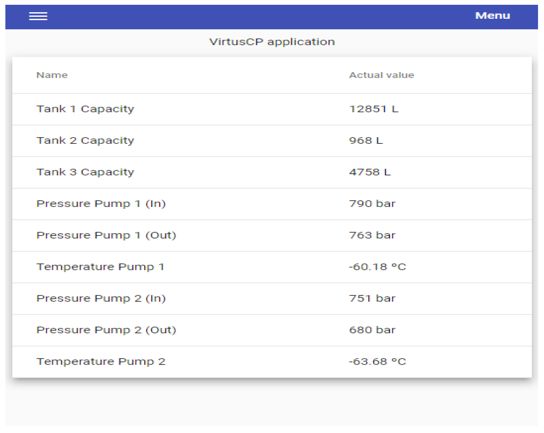
- Remote monitoring of technical parameters provided from site sensors.
- Use of industry standard protocols to communicate with different equipment—dispensers and sensors—in the refueling station.
- Fault tolerance. System downtime must be avoided in case of internet connection loss, server crash, or even any other device failure.
3.3. Sub-Systems and Their Interfaces
- Hardware at each facility. This is needed to run the user interface and to communicate with gas dispensers during the refueling process. This hardware is also needed to run the software reading sensor values.
- Software at each facility. This is software running on the above-mentioned hardware. It must serve as the user interface during the refueling process and read and synchronize sensor data with centralized cloud-based software. The hardware and software bundle installed on site is known as the “controller”.
- Software in the cloud. Centralized software allowing remote access. Its mission is to maintain the fleet’s data, record its refueling, and obtain useful information from all of this. It must also register sensor values read by controllers from any site and offer tools for their correct monitoring. Finally, it must offer the functionality to synchronize data (fleet, refueling, and technical parameters) with the company’s controller network.
- Internet of Things (IoT). The gas facilities’ controllers should be as lightweight as possible. All of them working together and linked to their central system meet the IoT philosophy.
- Fog computing. This approach is a design philosophy derived from “Cloud Computing”. It establishes that data used and generated by a system must be stored as physically close to the site as feasible. This philosophy is not always applicable and often leads to complications in software design, but it makes systems faster and more robust. One of the features that any system must meet is precisely its robustness. This system is especially critical, as noted in the requirements list. Should the controllers stop working, vehicles will not be capable of refilling and facilities will no longer be monitored. Site operations must not be dependent on connectivity to a central office, as facilities are often located in areas where internet coverage is poor. Hence, a fog computing approach is proposed. This concept does not need an online connection for its operation. The information needed for the controllers to operate is distributed throughout its own network via a synchronization process which keeps them updated when communication with the cloud is available.
- Redundancy. Given the critical nature of the system, its design must consider the option of having more than one controller at each refueling site. Thus, if one fails, another controller can take over.
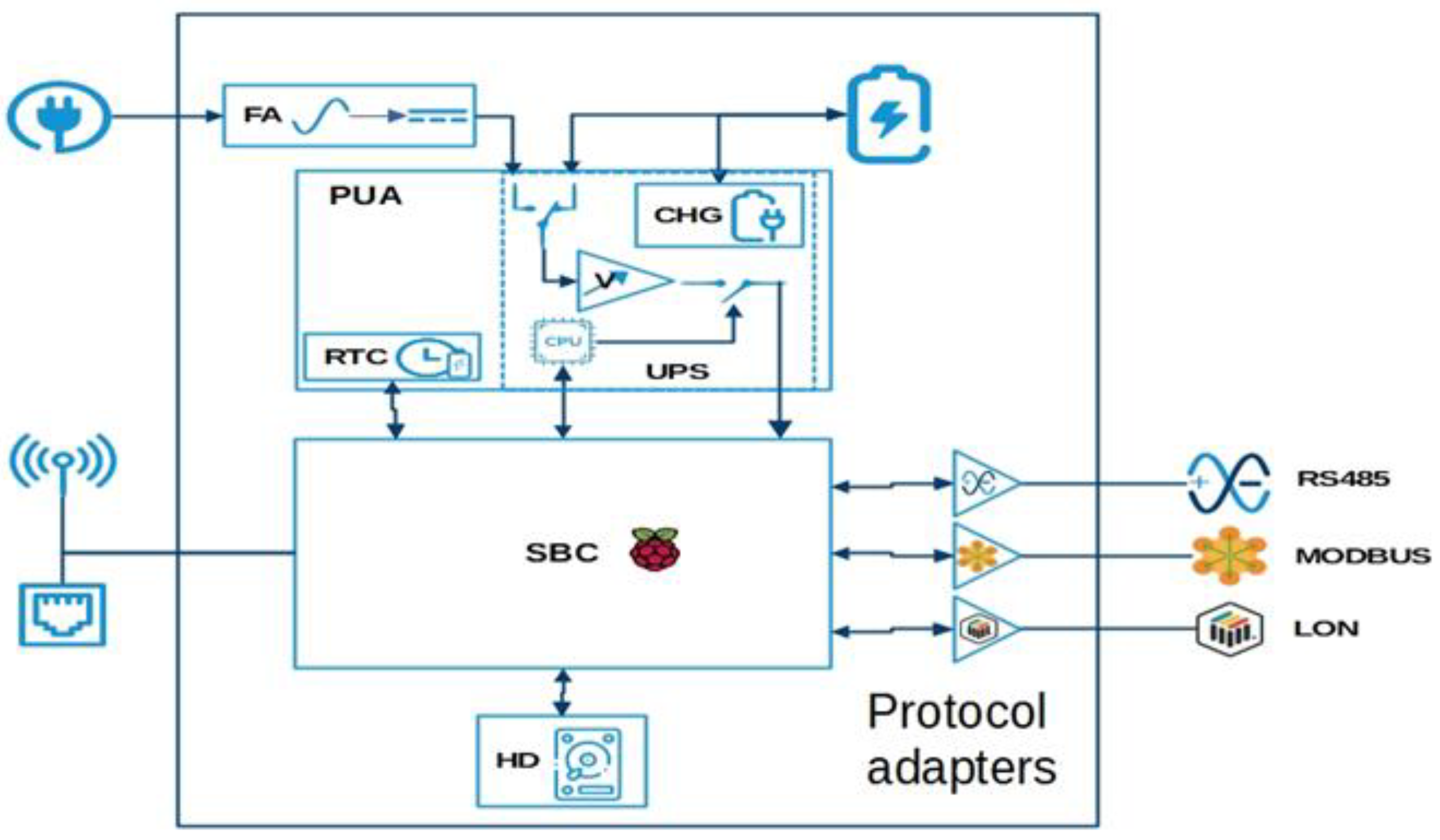
3.4. Hardware Sub-System
- It must be able to interact with users (HGV drivers) to complete the refilling procedure.
- It must be light and robust, as it will often be installed outdoors.
- It must be able to communicate with on-site devices (gas dispensers and sensors).
- It must be able to maintain facilities in operation even if there is no connectivity to headquarters.
- It reduces costs by decreasing the number of circuit boards required and eliminating the connectors and bus controller circuits that would otherwise be used.
- It saves space by having a compact and lightweight design which can be easily integrated into other systems or products.
- It facilitates the IoT (Internet of Things) by allowing various devices and sensors to be connected through standard or custom interfaces.
- It offers flexibility by being able to choose between different models and configurations of SBCs according to the needs of the project.
- Higher cost by requiring more engineering and design than ordinary computers.
- Not easily upgradeable because it is built as a fixed structure that does not allow adding or changing components.
- Intimidating when using Linux and non-removable hardware which can be difficult for inexperienced users to manage.
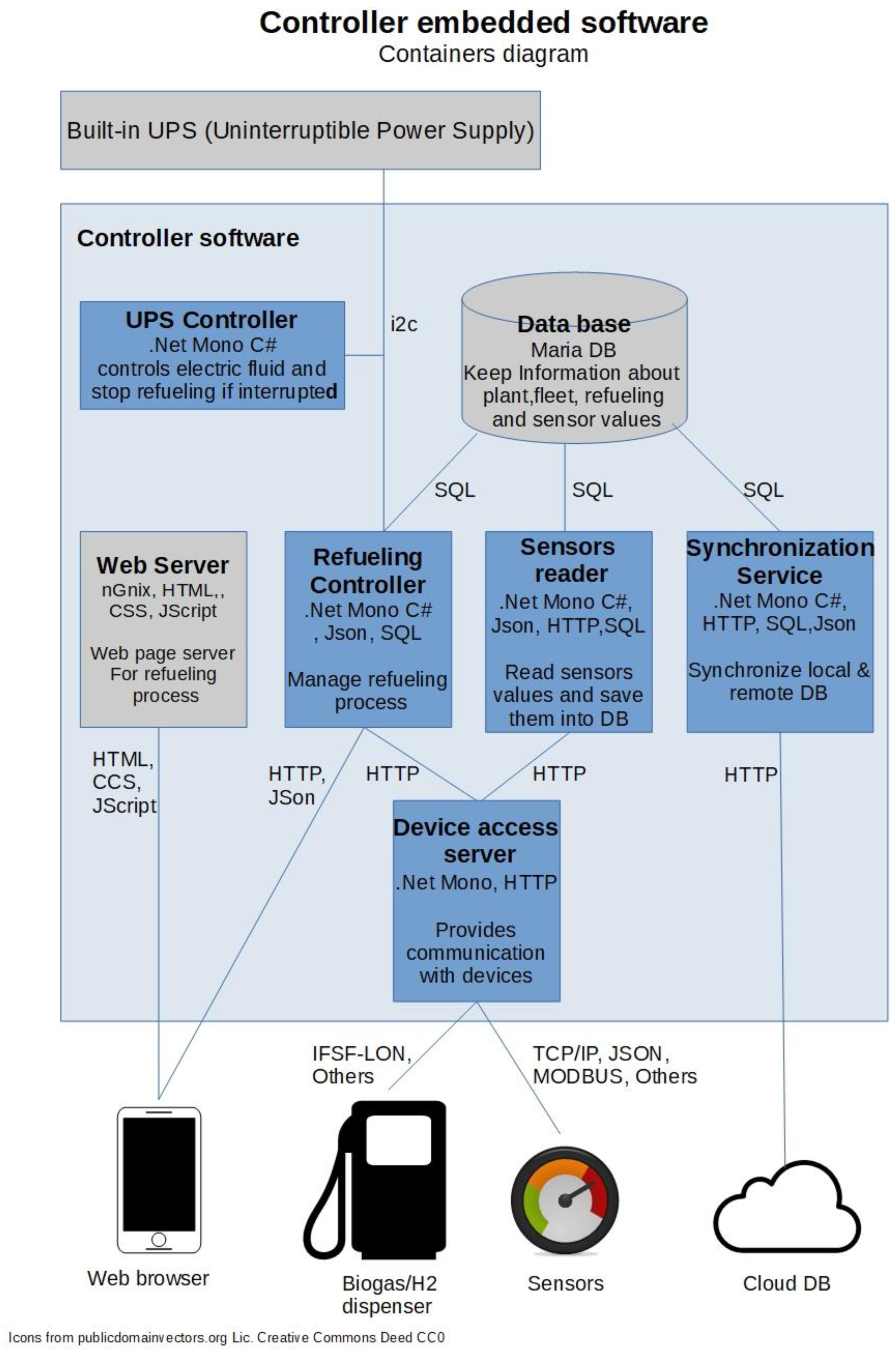
3.5. Controller Embedded Software
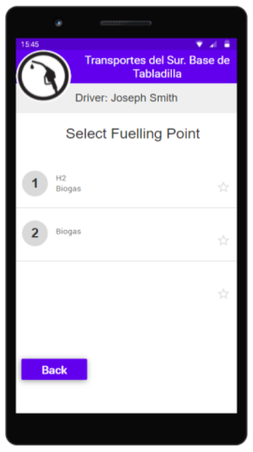
- Provide a user interface for the refueling procedure.
- Communicate with on-site devices—biogas or H2 dispenser and sensors—to control the refueling process and read parameter values from such devices.
- Keep the controller running (thus refueling activities) even without an internet connection to the monitoring office.
- The driver’s mobile interface for the refueling procedure must be easily accessible and user-friendly.
- It must be able to communicate with gas dispensers and the array of sensors on site, using the most common protocols in the industry. Therefore, the most popular dispenser protocol, IFSF-LON [14], and one of the most commonly used protocols for measurement devices and sensors, JSON over TCP/IP [15], have been selected for the prototype. However, software architecture must be flexible enough to incorporate more protocols in the future, thus supporting a variety of managed devices using different protocols at a specific location.
- Linux operating system, Debian 10 distribution. Linux OS is suitable for running on an SBC platform. The Debian 10 distribution is lightweight and known for its robustness [16].
- C#/Net core framework as back-end programming language. It is a widespread and robust development tool, which has proven its usefulness for this type of project. The core version is used to ensure that the framework remains lightweight—it runs on an SBC device—and compatible with Linux OS [17].
- Maria DB database. Required since the device must be capable of storing substantial amounts of data by applying a “fog computing” approach. Maria DB is powerful enough for this purpose, and it is an extremely lightweight database server [18].
- NGINX web server. Essential to provide web pages comprising the user’s refueling interface. NGINX is a well-known and dependable lightweight server which is ideal to run on an SBC device [19].
- HTML, CSS, and JavaScript as front-end languages. Used to build the web user interface. All of them are widespread, robust, and also lightweight enough to run on users’ mobile devices [20].
- HTTP protocol and JSON data format to synchronize information with the cloud-based host server. JSON is remarkably simple and lightweight, ideal for communicating messages over the internet [21].
3.6. Centralized Cloud Software
- The fleet refueling management and site monitoring software must be accessible remotely and simultaneously by an undetermined number of users.
- Provide access to property configuration of each facility (fuel types, storage tanks or racks, controllers, dispensers, sensors, etc.) and fleet assets (vehicles and drivers).
- Allow access to site refueling operations with the capability to retrieve aggregated data from them.
- Display and monitor readings provided by sensors at each station.
- Control on-site fuel wet stock, including input management from suppliers or self-generated production.
- Regular communication with site controllers to keep fleet data and refueling and sensor values synchronized. Once per minute seems a reasonable frequency for this task.
- Simple and intuitive interface for users.
- Security against non-authorized access. Simplicity and maintenance reasons make it desirable to run one application with a single database for all companies using the system. Moreover, it must ensure that users can only access data pertaining to their company.
- Scalability. The system shall ensure efficiency even when managing large numbers of vehicles, refueling plants, sensors, and/or users.
- Regional customization. Selecting measurement units (metric or imperial) and language.
- Responsiveness. It must be designed in such a way that its interface meets browsers’ resolution and appearance on a computer, mobile phone, or tablet.
- Web server. NGINX or Apache will be used as they are robust, scalable, and well-known servers.
- C#/Net 5 as back-end programming language and framework. This is an extended and robust tool, which has proven useful for this type of project. Version 5 is used to ensure that the framework is compatible with Linux and Windows operating systems [22].
- Protocols and data format of the web API used to synchronize with controllers: HTTP and JSON. These are lightweight and powerful protocols suitable for transferring data over the internet.
- HTML, CSS, and JavaScript as front-end languages. Used to build the web user interface. All of them are widespread and robust. They are also light enough to run on any device (PC, tablet, or mobile phone).
- PostgreSQL database server. It is a widely used open-source database, robust, powerful, and easy to scale [23].
- JasperReports engine. It is essential for easy presentation of aggregated data. It is a well-known, free, and robust report generator, especially designed for use in web applications [24].
- HOST operating system: as a result of implementing the above technologies, this application could be installed on multiple platforms.
4. Results
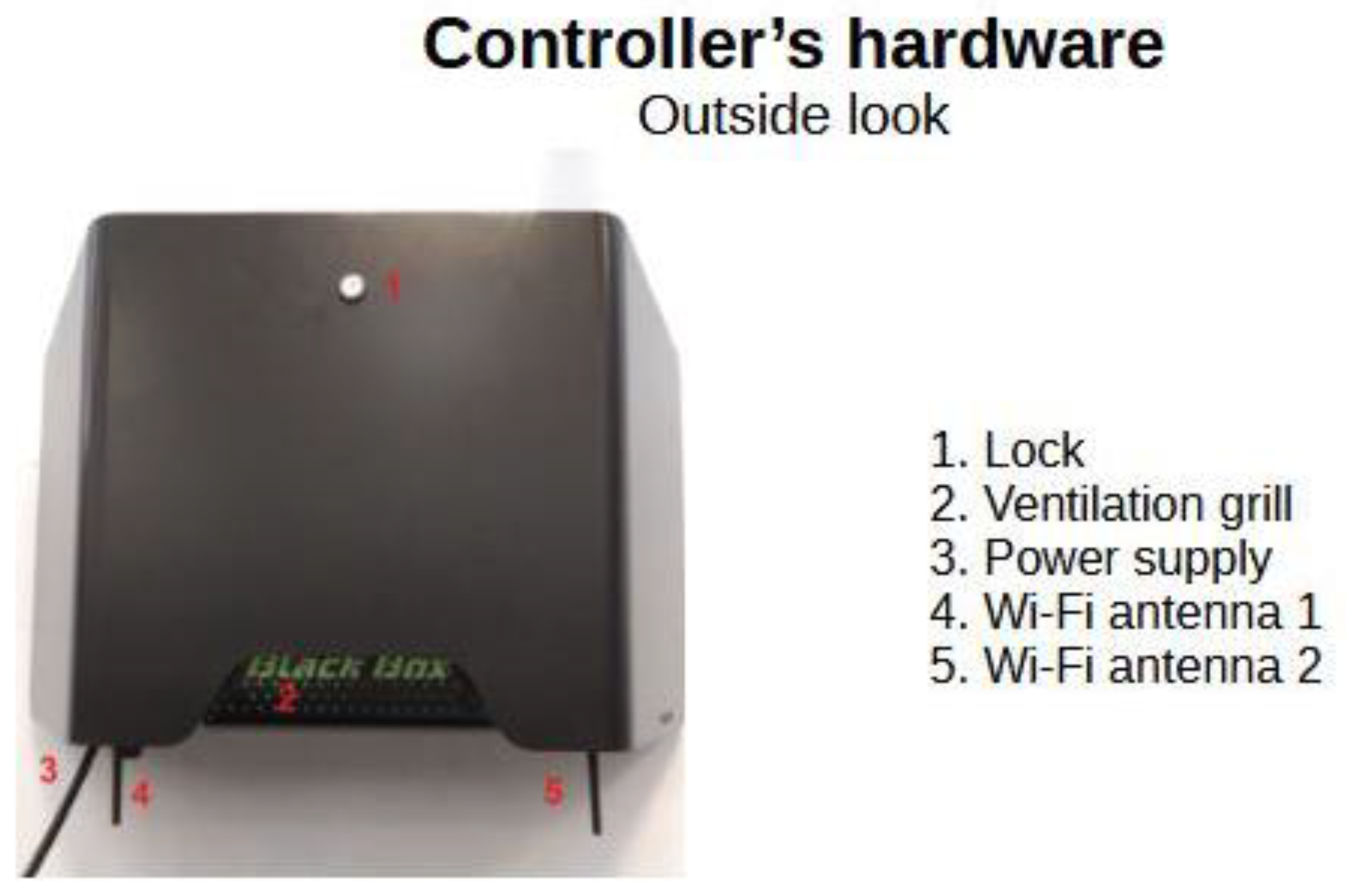
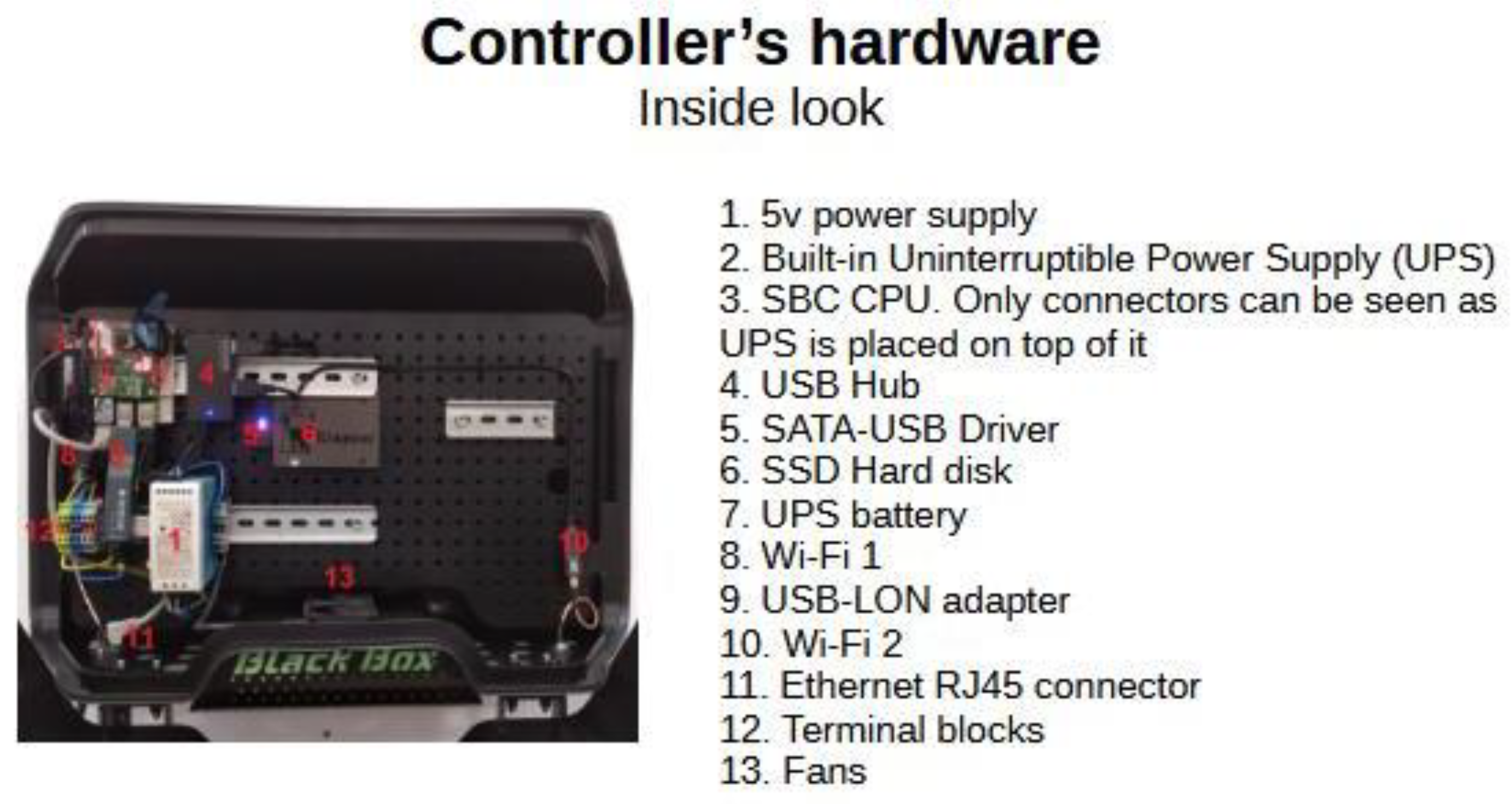
4.1. Controller’s Hardware
- System start-up. The controller does not have an on–off switch. The only way to turn it on was by plugging it into an external power supply (230 V AC). Then, the controller booted up successfully. The Linux’s shell operating system appeared ready and all components (HD drive, Wi-Fi, USB-LON device, Ethernet, and i2c interfaces) were up and running.
- System shutdown. As mentioned above, the only way to turn the system off is by disconnecting it from the power supply. However, this process is a bit more complex than powering up. The controller must shut down in an orderly manner. The custom-designed electrical circuit detects the power outage and uses its internal battery to keep the controller running for a certain period of time. A purpose-built software process detects this circumstance, triggering a command sequence to terminate any active refueling, saving information in the database, closing down the operating system, and cutting off power to the CPU and all other devices.
- Temperature test. All hardware components have been selected to meet the extended range of ambient temperature requirements (−20 °C/+60 °C). This range is sufficient for equipment installed outdoors. Other than the CPU, no components require additional cooling systems. A fan has been included in the design to prevent the CPU from reaching temperatures exceeding its operating range (+85 °C). During the prototype validation phase, a heat chamber was used to raise the ambient temperature to 60 °C, while the CPU did not exceed 70 °C running highly demanding tasks. The certification of the prototype has not been considered. Nevertheless, any marketable equipment must be certified.
- Dust- and waterproof. Equipment installed outdoors must meet at least an IP54 protection rating. The metal enclosure housing all the devices was designed to meet this requirement. No testing for this protection rating was carried out apart from installing the prototype outdoors for a one-month period. Prototype certification was not considered advisable, as the unit may still be subject to modifications before reaching a final commercial stage. As stated above, the marketable product must be certified to meet this requirement.
- Electromagnetic compatibility. Although this requirement is not explicitly stated, all electronic devices manufactured in the European Union must undergo electromagnetic compatibility compliance tests to achieve a CE Marking. This obligation was considered during the design process, but it was not deemed appropriate to certify the controller at the prototype stage. The commercial product derived from it shall be certified to all applicable regulations.
4.2. Controller’s Embedded Software
4.3. Cloud Software
5. Discussion
5.1. Hardware
5.2. Controller’s Software
5.3. Management Software
6. Conclusions
- It is viable and fully meets the demands for green refueling facilities.
- New challenges and opportunities for its improvement were detected.
Author Contributions
Funding
Data Availability Statement
Acknowledgments
Conflicts of Interest
References
- Decarbonising Road Transport—The Role of Vehicles, Fuels and Transport Demand. Available online: https://www.eea.europa.eu/publications/transport-and-environment-report-2021/download (accessed on 13 March 2023).
- Will Electric Trucks Be in It for the Long Haul? Available online: https://www.commercialfleet.org/fleet-management/will-electric-trucks-be-in-it-for-the-long-haul (accessed on 13 March 2023).
- Europe’s Truck Giants to Ditch Diesel, as Hydrogen’s Benefits Come to Fore. Available online: https://www.euractiv.com/section/energy/news/europes-truck-giants-to-ditch-diesel-as-hydrogens-benefits-come-to-fore/ (accessed on 14 March 2023).
- Road Freight Decarbonization in Europe. Readiness of the European Fleets for Zero Emission Trucking. Available online: https://theicct.org/wp-content/uploads/2022/09/road-freight-decarbonization-europe-sep22.pdf (accessed on 14 March 2023).
- Bonomi, F.; Milito, R.; Zhu, J.; Addepalli, S.K. Fog computing and its role in the internet of things. In Proceedings of the First Edition of the MCC Workshop on Mobile Cloud Computing; ACM SIGCOMM 2012 Conference, Helsinki, Finland, 17 August 2012; pp. 13–16. [Google Scholar]
- How a Hydrogen Filling Station Works. Available online: https://www.roadandtrack.com/car-culture/g6917/how-hydrogen-filling-stations-work/ (accessed on 15 March 2023).
- European Train the Trainer Programme for Responders. Lecture 12: Hydrogen Refueling Stations & Infrastructure. Chapter 5: Safety Features in HRS and Other Infrastructures, pp. 35–37. Available online: https://hyresponder.eu/wp-content/uploads/2021/06/L12_HyResponder_L4_210622.pdf (accessed on 15 March 2023).
- Royce, W.W. Managing the Development of Large Software Systems. 1970. Available online: https://blog.jbrains.ca/assets/articles/royce1970.pdf (accessed on 16 March 2023).
- Kruchten, P.B. The 4 + 1 View Model of Architecture. IEEE Softw. 1995, 12, 42–50. [Google Scholar] [CrossRef]
- The C4 Model for Visualising Software Architecture. Available online: https://c4model.com/ (accessed on 16 March 2023).
- Bacon, C.J. The Use of decision criteria in selecting information systems/technology investments. MIS Q. 1992, 1, 335–353. [Google Scholar] [CrossRef]
- Isikdag, U. Internet of Things: Single-Board Computers. Enhanced Building Information Models: Using IoT Services and Integration Patterns; Springer: New York, NY, USA, 2015; pp. 43–53. ISBN 978-3-319-21824-3. [Google Scholar]
- Bolton, W. Programmable Logic Controllers; Newnes: Oxford, UK, 2015; ISBN 9780081003534. [Google Scholar]
- IFSF—International Forecourt Standards Forum. Available online: https://ifsf.org/ (accessed on 17 March 2023).
- Nurseitov, N.; Paulson, M.; Reynolds, R.; Izurieta, C. Comparison of JSON and XML data interchange formats: A case study. Caine 2009, 9, 157–162. [Google Scholar]
- Debian—The Universal Operating System. Available online: https://www.debian.org/index.en.html (accessed on 17 March 2023).
- C# Documentation—Get Started, Tutorials, Reference. Microsoft Learn. Available online: https://learn.microsoft.com/en-us/dotnet/csharp/ (accessed on 20 March 2023).
- MariaDB Server: The Open Source Relational Database. Available online: https://mariadb.org/ (accessed on 20 March 2023).
- NGINX—Advanced Load Balancer, Web Server & Reverse Proxy. Available online: https://www.nginx.com/ (accessed on 20 March 2023).
- Dinh, D.; Wang, Z. Modern Front-End Web Development: How Libraries and Frameworks Transform Everything. Bachelor’s Thesis, Turku University of Applied Sciences, Turku, Finland, 2020. Available online: https://www.theseus.fi/bitstream/handle/10024/342325/Thesis-Duong-Wang.pdf (accessed on 20 March 2023).
- Bray, T. The JavaScript Object Notation (JSON) Data Interchange Format. RFC 8259, Last Updated December 2017. Available online: https://datatracker.ietf.org/doc/rfc8259/ (accessed on 21 March 2023).
- Price, M.J. C# 9 and NET 5—Modern Cross-Platform Development: Build Intelligent Apps, Websites, and Services with Blazor, ASP. NET Core, and Entity Framework Core Using Visual Studio Code; Packt Publishing Ltd.: Birmingham, UK, 2020. [Google Scholar]
- Juba, S.; Vannahme, A.; Volkov, A. Learning PostgreSQL; Packt Publishing Ltd.: Birmingham, UK, 2015; pp. 38–43. [Google Scholar]
- TIBCO Jaspersoft—Reporting and Embedded Business Intelligence Software. Available online: https://www.jaspersoft.com/ (accessed on 21 March 2023).
- The RS-485 Design Guide (Rev. D). Available online: https://www.ti.com/lit/pdf/slla272?keyMatch=RS-485 (accessed on 21 March 2023).
- Directive 2014/34/EU of the European Parliament and of the Council of 26 February 2014. Available online: https://eur-lex.europa.eu/legal-content/EN/TXT/PDF/?uri=CELEX:32014L0034 (accessed on 20 March 2023).
- Swales, A. Open modbus/tcp specification. Schneider Electr. 1999, 29, 3–19. [Google Scholar]
- EECS—AIB. Available online: https://www.aib-net.org/eecs (accessed on 22 March 2023).


Disclaimer/Publisher’s Note: The statements, opinions and data contained in all publications are solely those of the individual author(s) and contributor(s) and not of MDPI and/or the editor(s). MDPI and/or the editor(s) disclaim responsibility for any injury to people or property resulting from any ideas, methods, instructions or products referred to in the content. |
© 2023 by the authors. Licensee MDPI, Basel, Switzerland. This article is an open access article distributed under the terms and conditions of the Creative Commons Attribution (CC BY) license (https://creativecommons.org/licenses/by/4.0/).
Share and Cite
Martín-Márquez, A.; Rangel-Serrano, J.F.; Oyola-González, J.M.; Talegón-Vázquez, A.; Garrido, M.; García-Velayos, R.; García-Heras, C.P.; Bolonio, D.; Ortega-Romero, M.F. Green Fleet: A Prototype Biogas and Hydrogen Refueling Management System for Private Fleet Stations. Fuels 2023, 4, 314-332. https://doi.org/10.3390/fuels4030020
Martín-Márquez A, Rangel-Serrano JF, Oyola-González JM, Talegón-Vázquez A, Garrido M, García-Velayos R, García-Heras CP, Bolonio D, Ortega-Romero MF. Green Fleet: A Prototype Biogas and Hydrogen Refueling Management System for Private Fleet Stations. Fuels. 2023; 4(3):314-332. https://doi.org/10.3390/fuels4030020
Chicago/Turabian StyleMartín-Márquez, Antonio, José Francisco Rangel-Serrano, José Manuel Oyola-González, Adrian Talegón-Vázquez, Mario Garrido, Rodrigo García-Velayos, Carla Patricia García-Heras, David Bolonio, and Marcelo F. Ortega-Romero. 2023. "Green Fleet: A Prototype Biogas and Hydrogen Refueling Management System for Private Fleet Stations" Fuels 4, no. 3: 314-332. https://doi.org/10.3390/fuels4030020
APA StyleMartín-Márquez, A., Rangel-Serrano, J. F., Oyola-González, J. M., Talegón-Vázquez, A., Garrido, M., García-Velayos, R., García-Heras, C. P., Bolonio, D., & Ortega-Romero, M. F. (2023). Green Fleet: A Prototype Biogas and Hydrogen Refueling Management System for Private Fleet Stations. Fuels, 4(3), 314-332. https://doi.org/10.3390/fuels4030020