Article

Spray Analysis and Combustion Assessment of Diesel-LPG Fuel Blends in Compression Ignition Engine

1
Department of Chemical, Materials and Production Engineering, University of Naples Federico II, via Claudio, 21, 80125 Naples, Italy
2
CNR–STEMS, Viale Marconi, 4, 80125 Naples, Italy
*
Author to whom correspondence should be addressed.
Fuels 2021, 2(1), 1-15; https://doi.org/10.3390/fuels2010001
Submission received: 6 November 2020 / Revised: 23 December 2020 / Accepted: 28 December 2020 / Published: 31 December 2020

Abstract

:
A major challenge for internal combustion engines (ICEs), and diesel engines, in particular, is the reduction of exhaust emissions, essentially nitrogen oxides (NOx) and particulate matter (PM). In this regard, the potential of LPG-diesel blends was evaluated in this work. The LPG and diesel blends were externally prepared by exploiting their perfect miscibility at high pressures. Two diesel-LPG mixtures with 20% and 35% by mass LPG concentrations were tested. In terms of spatial and temporal evolution, the spray characterization was performed for the two blends and pure diesel fuel through high-speed imaging technique. The combustion behavior, engine performance and exhaust emissions of LPG-diesel blends were evaluated through a test campaign carried out on a single-cylinder diesel engine. Diesel/LPG sprays penetrate less than pure diesel. This behavior results from a lower momentum, surface tension and viscosity, of the blend jets in comparison to diesel which guarantee greater atomization. The addition of LPG to diesel tends to proportionally increase the spray cone angle, due to the stronger turbulent flow interaction caused by, the lower density and low flash-boiling point. Because of improved atomization and mixing during the injection phase, the blends have shown great potential in reducing PM emissions, without affecting engine performance (CO2 emissions). The addition of LPG resulted in a significant smoke reduction (about 95%) with similar NOx emissions and acceptable THC and CO emissions. Furthermore, the low cetane number (CN) and high low-heating value (LHV) ensuring leaner air-fuel mixture, and improvements in terms of efficiency, particularly for a blend with a higher concentration of LPG.

1. Introduction

Any combustion process strongly depends on the fuel properties, as are emissions, which directly impact the environment. As for internal combustion engines, increasingly stringent emission regulations have forced the automotive industry to seek innovative and efficient technologies. In particular, for compression ignition (CI) engines, the goal is to reduce the NOx-soot trade-off. Several technologies are being developed on a diesel engine, thanks to the favorable thermodynamics and mechanics, to improve the trade-off further, also taking into account CO2 emissions. However, the study of the combustion system still represents the main cornerstone. As is known, up to 2015 the optimization of piston bowl [1], intake ports, EGR, turbocharger [2] and fuel injection system [3] was mainly directed to increase performance [4], reaching important milestones. Nowadays, researchers and OEM companies, are working hard on the development of new fuel and combustion concepts capable of improving both efficiency, performance and emissions. To this end, new combustion concepts and hardware for compression ignition engines are developed. This scenario also includes powering engines with Liquefied Petroleum Gas (LPG)-diesel blends, thus exploiting the potential of such fuel, such as high efficiency and low emission values of nitrogen oxides (NOx) and particulate matter (PM) [5].
This new concept consists of the injection of the LPG-diesel blend (external mixture formation) directly into the combustion chamber during the engine cycle’s high-pressure phase. The flame ignition is triggered by the higher reactive diesel fuel [6]. LPG has justified thanks to the high volatility and low reactivity (cetane number, CN), which are valuable characteristics that allow a leaner mixture formation compared to the conventional diesel combustion.
Studies performed on LPG-diesel blends have generally found a reduction of soot and NOx emissions. DH Qi et al. [7] demonstrated that this technique provides more significant control of NOx and particulate emissions on existing diesel engines by making simple fuel system changes. Also, Donghui et al. [8] using an LPG / diesel blend observed longer ignition delays, resulting in better air-fuel mixing and reduced soot emissions, but a worsening efficiency and HC emissions. J Cao et al. [9] conducted engine and spray tests using the blends with different LPG percentages. Regarding the engine tests, the results are aligned with what has already been described above. Regarding the spray characterization, improved fuel atomization was observed, with a reduction in the Sauter Mean Diameter (SMD). It demonstrates, as noted above, how fuel characteristics affect engine performance and emissions [10].
Therefore, the combustion process depends significantly on spray characteristics. Since the LPG is mixed with the diesel, the fuel atomization will no longer rely only on the liquid bulk disintegration and the evaporation and coalescence of the droplets. These phenomena cause a considerable decrease in both the average number of droplets and a different redistribution [11]. Therefore, the use of mixed blends, with miscible fuels characterized by different thermodynamic properties, is of practical and fundamental importance [12,13].
The use of natural gas mixed with diesel is a valid alternative to LPG [14]. However, LPG can provide more flexibility for practical automotive applications as it is easier to manage in terms of storage and it can be stored in a liquid state at a pressure relatively lower than that of natural gas [15]. Furthermore, it guarantees a cooling effect of the combustion chamber thanks to evaporation’s latent heat, which allows to increase the power and decrease the exhaust emissions [16]. However, there are still many technical issues to be addressed in applying LPG to a compressed-ignition light-duty engine, starting with the correct and safe management of the right LPG-diesel ratio.
The activity is part of a broader research topic aiming to use the LPG-Diesel mixture in a CI engine through the conventional injection system adaptation with few modifications. This study’s main purpose is to evaluate the real potential of this new concept and its applicability on state-of-art engines. With its methodology and analysis conducted, the present study aims to cover the information and the scientific gap with what is present in the literature. There are no or very few results that characterize this new fuel concept in real operating conditions. Additionally, it is worth highlighting the originality of the method adopted and the potential in using LPG as an additive in diesel fuel. Based on the preliminary analysis on the use of LPG/Diesel blends [17,18], the present work focuses on studying the fuel-engine interaction to evaluate the effects of blends on engine outputs, with particular attention to the combustion process and pollutant emissions.
Two diesel-LPG mixtures with 20% and 35% by mass LPG concentrations were tested, named “DLPG20” and “DLPG35” respectively. Extensive engine tests were carried out through a single-cylinder engine (SCE). The effect of adding LPG on spray development was also investigated in a quiescent chamber through high-speed shadowgraph imaging. In particular, the information obtained from the spray characterization supports the tests on the single-cylinder, as they provide fundamental information on the spray quality, which strongly affects combustion and emissions.

2. Materials and Methods

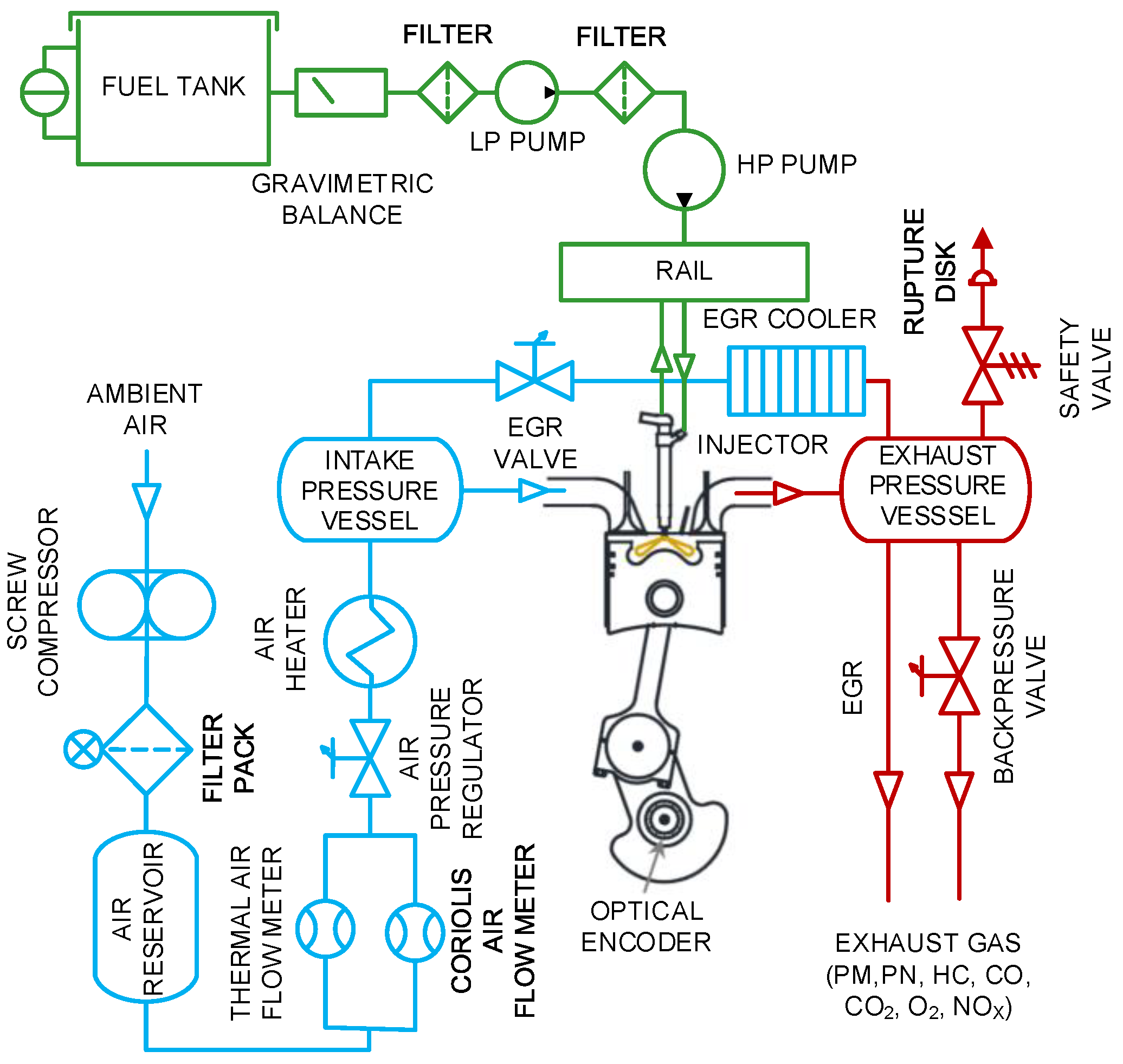
2.1. Single Cylinder Engine
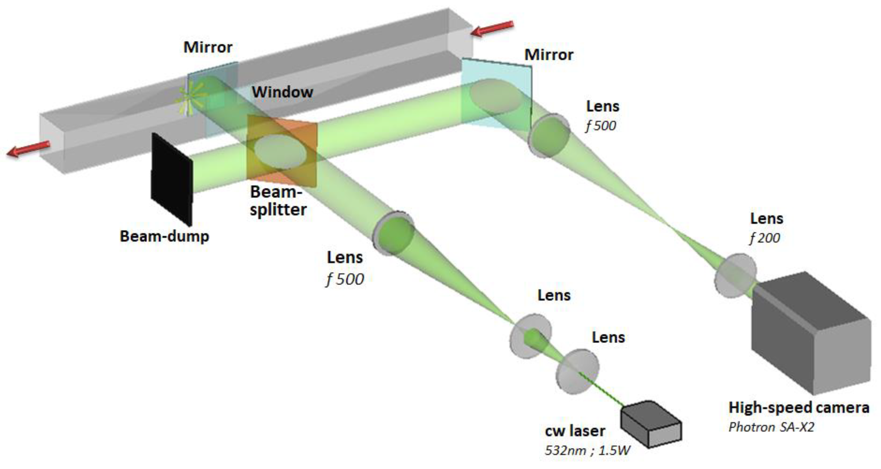
The new fueling concept was tested on a single-cylinder CI engine [19] derived from a multi-cylinder engine whose cylinder head has been suitably modified. The boundary conditions (intake, exhaust and cooling) are controlled independently of the engine operating point, allowing complete flexibility. The systems are managed through a home-developed control and acquisition system based on LabVIEW, which collects all test cell sensors’ low-frequency signals. The test cell layout is shown in Figure 1.
Also, the calibration settings (EGR level, energizing timing and number of the pulses, swirl ratio) are managed by an open-loop Electronic Control Unit (ECU) [18]. A Kistler piezo-electric pressure transducer was employed to record the in-cylinder pressure by an AVL Indimicro indicating system, which process in real-time the net HRR [10]. The gaseous emissions were measured using an AVL CEBII integrated emissions test bench, while an AVL 415S smoke meter measured the soot concentration. The engine characteristics are listed in Table 1. The fuel flow rate was calculated from the measured CO2 concentration using the carbon balance method [20] validated by the results obtained through an AVL 733 mass flow meter, employed for only diesel tests.

2.2. Optical Setup

In terms of spatial and temporal evolution, the spray characterisation was performed in a test bench suitably designed to perform tests in evaporating conditions. The experimental setup is schematically illustrated in Figure 2. The fuel spray was injected into a low velocity and heated air crossflow in a 100 mm square duct.
The spray development was characterized by high-speed shadowgraph imaging. A double-pass shadowgraph layout was made by simply removing the knife-edge in an in-line lens-type schlieren setup. The light source was a cw Nd: YAG laser (532 nm, 1.5 W). The in-line optical setup was made using two plano-convex lenses 500 mm focal length and 100 mm diameter. The spray evolution sequences were acquired at 50,000 fps using a high-speed camera (Photron FASTCAM SA-X2 type 1000 k-M2). The image resolution was 0.184 mm/pixel, and the exposure time was 0.29 µs. A 7 holes solenoid injector has been employed, whose characteristics are shown in Table 1.

2.3. Testing Methodology

The tests campaigns were performed to provide additional information when using LPG-diesel blends and assess the optimal L.P.G./diesel mass ratio. The tested points, listed in Table 2, were performed in steady-state conditions at fixed engine speed (2000 rpm) and varying the engine load conditions, using the reference multi-cylinder engine calibration. Also, the pumping losses, intake, and back-pressure parameters were set to simulate the turbocharger’s operating point. The test points performed were extensively used in past activities as reference points as characteristic points of the New European Driving Cycle (NEDC) and World Harmonized Light Vehicles (WLTP) homologation cycles [19]. Two engine load conditions were chosen, 2 and 5 bar of Brake Mean Effective Pressure (BMEP). The first represents low load conditions, the second one for being a critical condition about NOx and PM emissions. A previous study [18] was mainly devoted to evaluating the injection system performance with different working fluids and the engine-emissions adopting a conventional calibration without EGR. In this work, the investigation was aimed at an in-depth study on the combustion process mainly at part load, 2000 × 2, where problems related to the complete oxidation of the fuel could occur, and 2000 × 5 to evaluate the significant reduction of particulate emissions due to presence of LPG in the mixture. Both tested points were performed at a constant engine-out NOx level, varying the EGR rate.
The additional study was concerned with the experimental characterization of the spray, under non-evaporative and evaporative conditions, to assess the atomization characteristics among diesel and mixed fuels. The spray evolution was characterized by high-speed shadowgraph imaging [21]. The optical layout is schematized in Figure 2. To objectively evaluate the spray evolution for liquid/vapour phases, a customized algorithm developed in MATLAB® [22] was employed, capable of defining the spray’s macroscopic parameters, i.e., the spray tip penetration and cone angle. The spray penetration was calculated as the maximum axial distance of the jet contour from the injector tip. The cone angle, i.e., the angle of the cone enclosing the jet, was measured from a linear fit through the jet outer edges, where the origin is fixed at the injector tip.
The tests were carried out adopting the injection strategies used for the engine tests in terms of rail pressure and energizing time (ET) of pulses, while the combustion chamber conditions in terms of temperatures and back-pressures were not performed for the present work. Therefore, the rail pressures (prail) were set at 750 and 850 bar, at different chamber temperature (Tch) 300 K and 473 K (pch 1 bar), and the energizing timing of 0.6 ms. Five consecutive events were acquired for each injection condition to evaluate the mean value and the standard deviation. The injection conditions are summarized in Table 2.

2.4. Fuel Characteristics

LPG is a mixture of alkane hydrocarbons composed mainly of butane and propane. Table 3 shows the main thermodynamic properties of both fuels, indicating the properties of the mixtures obtained through linear interpolation. LPG is in the liquid state in a pressure range of 2–8 bar in ambient condition, while at p = 1 bar at 298 K (standard conditions), it is in the gaseous state. Likewise, by increasing the LPG mass percentage, the LHV (Low-Heating Value) and the heat of vaporization of the blend increase [18]. The LPG impact in the diesel fuel, in terms of the combustion characteristics and emissions of the engine, was assessed by testing the following fuels:
  • Commercial Diesel EN590.
  • DLPG20 →20% w/w, L.P.G. in diesel.
  • DLPG35 →35% w/w, L.P.G. in diesel.
Two different mixing levels of LPG in diesel were chosen. The choice of a blend with 20% is justified by the need to guarantee engine reliability, without significantly altering its characteristics. DLPG35 was chosen to assess, with a higher LPG level, its impact on combustion, performance, and emissions.
The fuel system was modified to ensure reliable operation based on the characteristics of the fuels. The system is a closed circuit at a pressure of about 8 bar, to guarantee fuel in the liquid state. The tank in which the mixture is prepared in the desired mass ratio can support pressures up to 20 bar. For more details of the injection system layout, refer to [23,24].

3. Results

The results section has been arranged into sub-sections. Firstly, the results of the experimental characterization of the spray are analyzed, highlighting the main differences compared to the reference diesel.

3.1. Spray Characterization of Diesel/LPG Blends

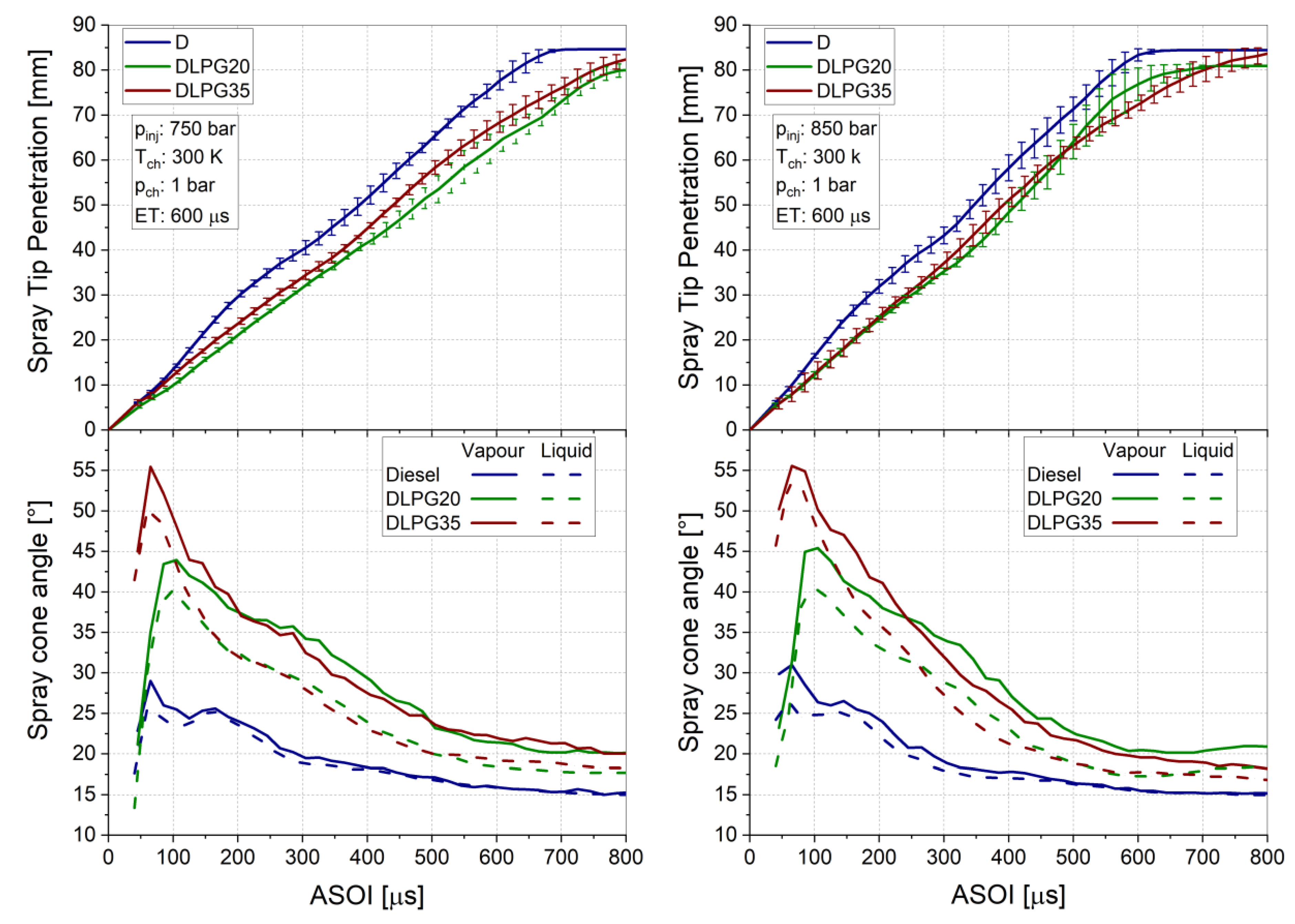
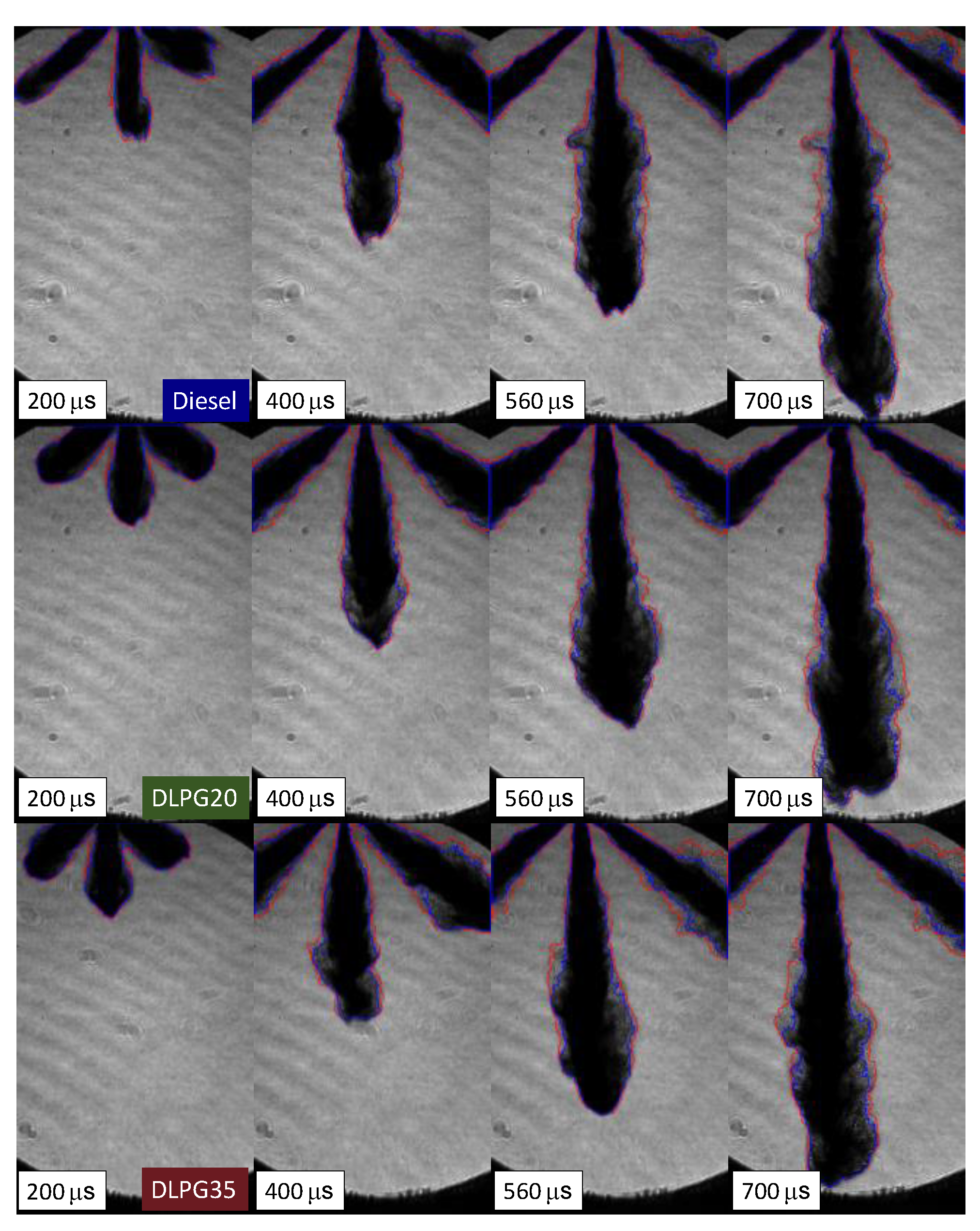
3.1.1. Non-Evaporation Condition (Tch = 300 K)

The spray tip evolution and cone angle against After the Start of Injection (ASOI) timing for diesel, DLPG20, and DLPG35 at different injection pressures (prail) are shown in Figure 3. All tested fuels behave similarly; the spray initially penetrates faster due to the low atomization in the first stage, after which it progressively slows down due to air entrainment and the decrease of the droplets’ momentum [25]. This behaviour results from a lower momentum of the jet, due to the lower density of the blends than diesel [26], and from lower surface tension and viscosity, which guarantee greater atomization [27]. As injection pressure increases, the differences in spray penetration between the fuels decrease because of higher spray momentum and lower drag forces [28].
Minor differences between the spray penetrations of the blends have been observed for both conditions.
The addition of LPG to diesel tends to proportionally increase the spray cone angle, due to the stronger turbulent flow interaction caused by a lower density and LPG vaporizing shortly after injection because of its low flash-boiling point [6]. The effect of LPG vaporization can be seen from the first stages of the injection event. Although varying the percentage of LPG in the steady-state injection phase, there are no differences in terms of spray diffusion for both the vapor and liquid phases. The standard deviation was omitted for graphic reasons but corresponded in a range of 2–4%. Furthermore, a higher injection pressure does not involve significant variations for both parameters considered for DLPG blends, while for diesel an affect up to 400 µs is evident [29].

3.1.2. Evaporation Condition (Tch = 473 K)

Figure 4 shows a sample sequence of spray images for the different fuels under evaporative conditions, at a rail pressure of 750 bar. The red and blue lines indicate the boundaries of the vapor phase and the liquid phase, respectively. Figure 5 shows the time evolution, at different injection pressures, of spray penetration and cone angle for the tested fuels.
As well as in non-evaporative conditions, diesel/LPG sprays penetrate less than pure diesel. However, due to the lower gas density, the differences are less marked than in non-evaporative conditions and are further reduced as rail pressure increases [27]. Figure 5 also shows the spray cone angle evolution in evaporating condition; it can be noted an increase of it, compared to diesel. This aspect is particularly evident also in Figure 4, at about 200 µs, a greater cone angle is observed for mixtures compared to diesel. It is due to the greater atomization, which further promotes the LPG vaporization. This affected the spray evolution in the steady-state phase, in particular at higher prail, causing a lesser spray cone angle because of the higher evaporating rate, evident after about 400 µs ASOI, when the angle is progressively reduced. Still, in non-evaporated conditions, it remains aligned on constant values. The increase in injection pressure, combined with the high temperature, unlike the non-evaporating case, also increases in spray penetration. Furthermore, a more significant difference is observed between the two blends, particularly on the penetration in the interval 450–700 µs.

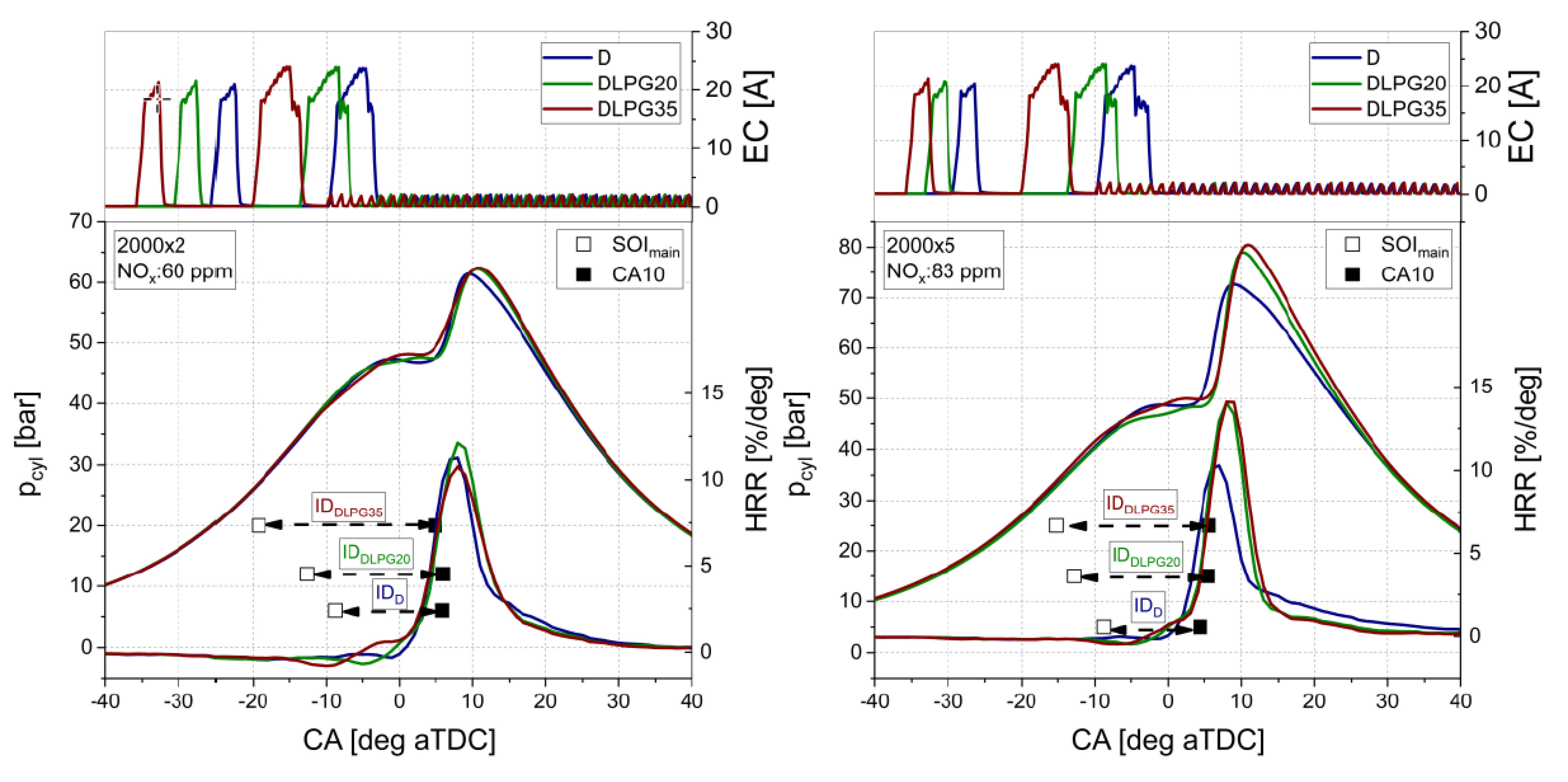
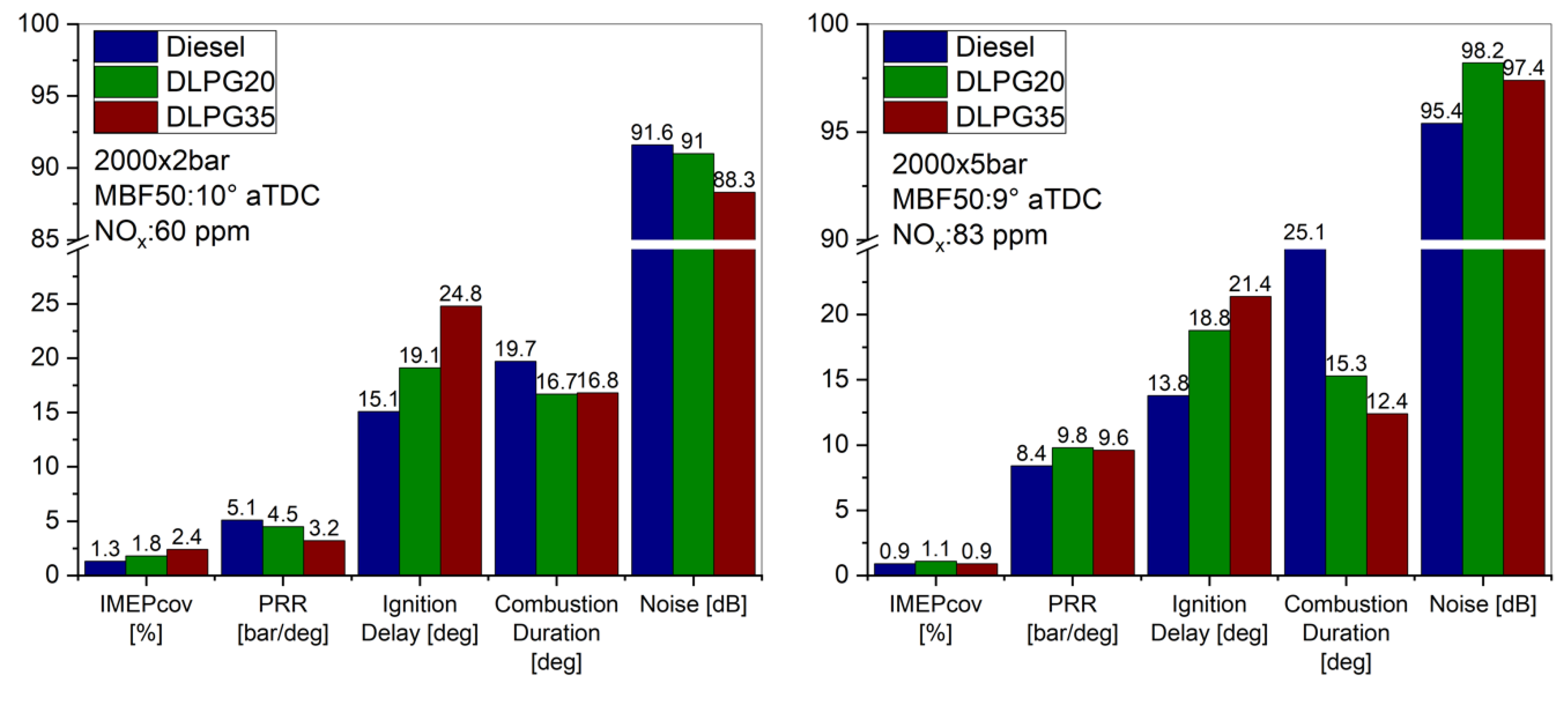
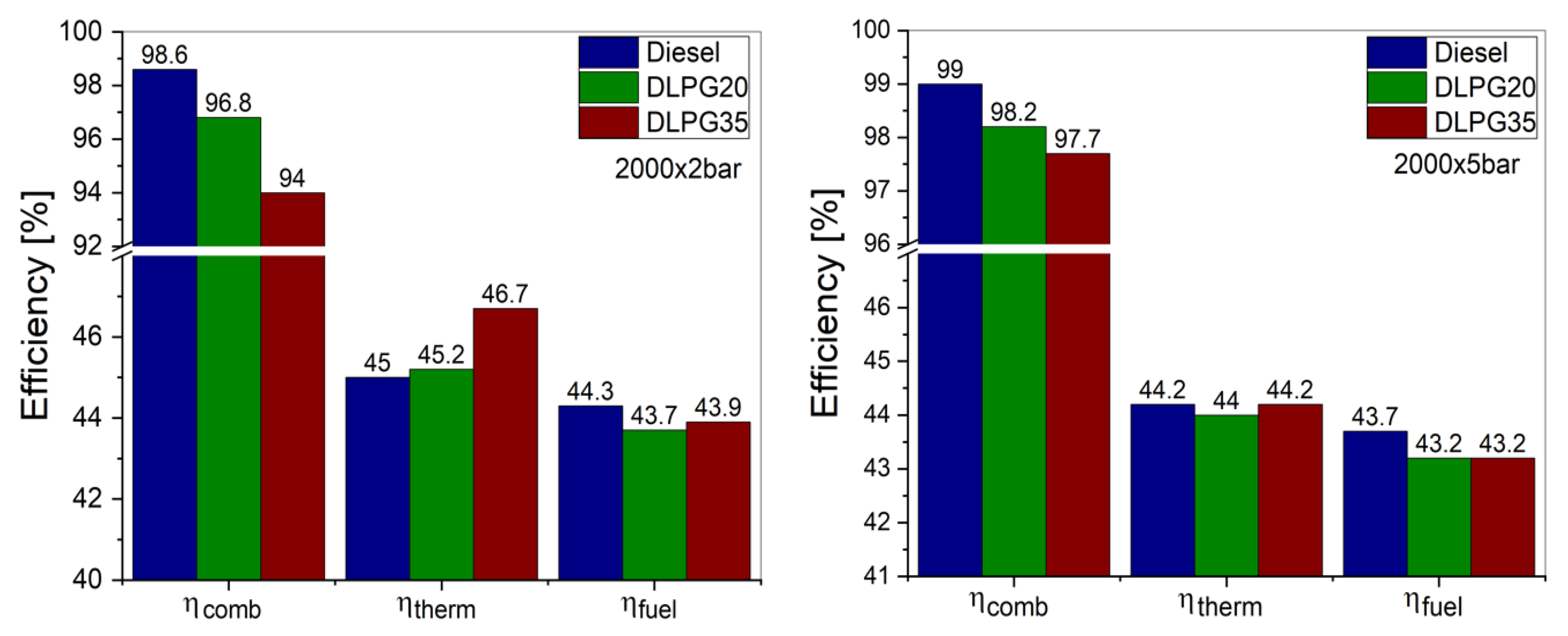
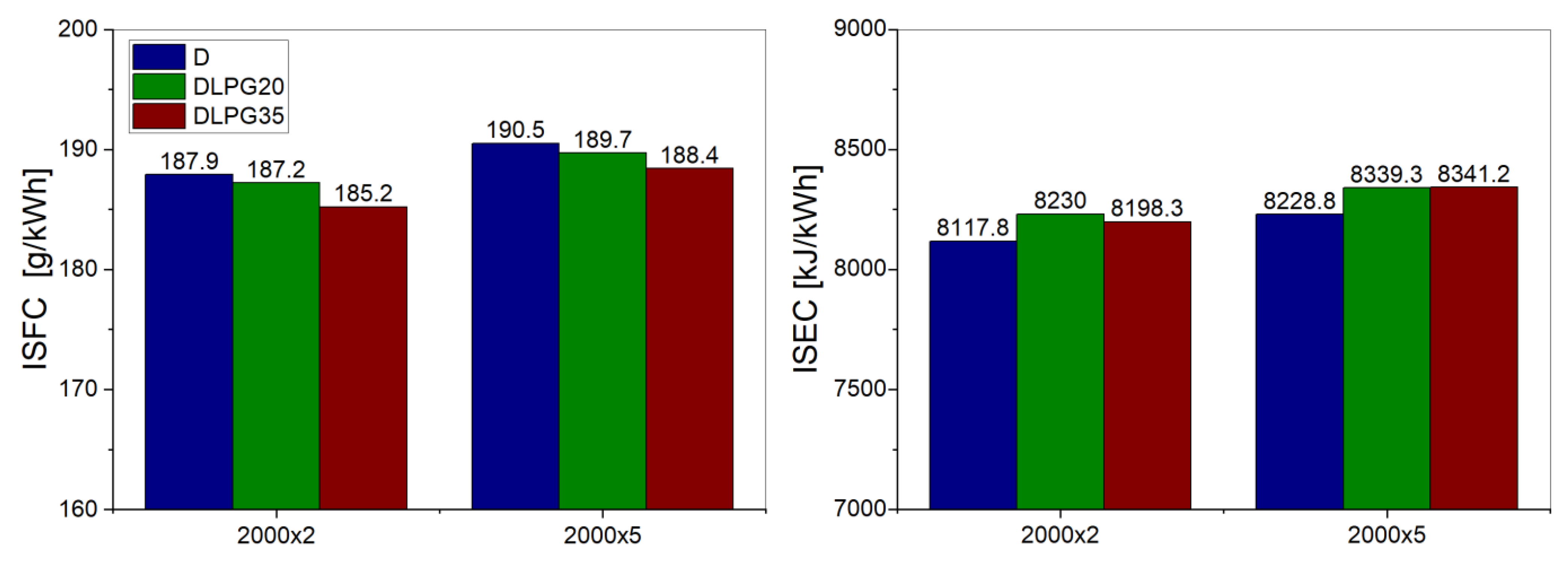
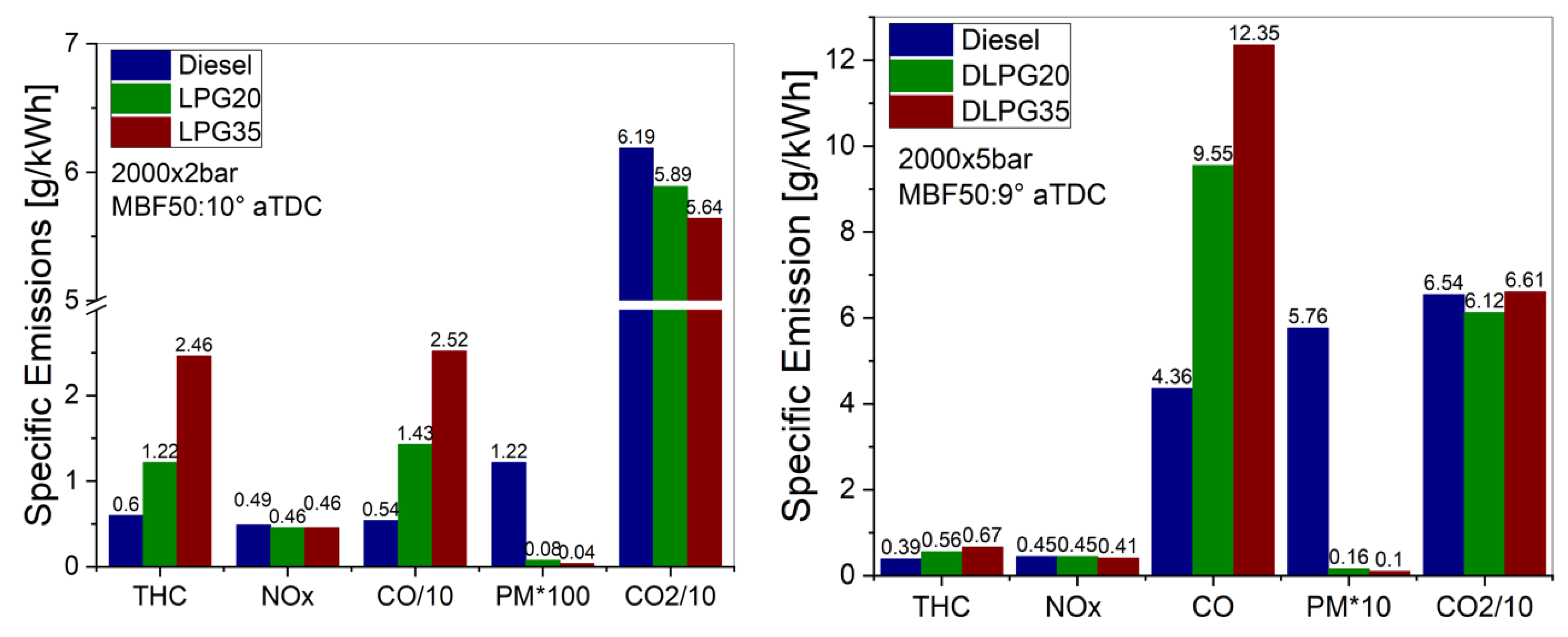
3.2. Combustion Analysis on SCE

In this section, an LPG-diesel blend assessment in terms of combustion, performance and emissions compared to the diesel is reported, for two test points in a steady-state condition. The tests were performed adopting a conventional injection strategy characterized by a pilot plus main injection, using EGR. The injection phasing and the energizing time of the main pulse (ETmain) were controlled to set the combustion phasing (CA50) and IMEP (Indicated Mean Effective Pressure) at the targets equal to the reference calibration value as reported in Table 2. The other injection parameters, such as ET (energizing time) of pilot pulse, dwell time, prail (rail pressure), were kept constant. The calibration settings are reported in the Testing Methodology section. For both test points, the EGR rate was varied to achieve the NOx target (Table 2).
The comparison between the in-cylinder pressure (pcyl) and the HRR shows a forward shift of the peak firing pressure (pfp), due to the pilot combustion’s ineffectiveness using LPG, and a corresponding increase of the maximum in-cylinder pressure. The combustion then moves from a diffusive mode, typical for diesel fuel, to a more premixed one, as evidenced by a reduced combustion duration [30]. The differences increase when increasing the LPG concentration. This can be ascribed to the high volatility of LPG and its very low cetane number, resulting in a lower auto-ignition tendency of the blends [6]. Different behaviour is observed with increasing the load. There is an increase in the HRR peak compared to diesel. This is probably due to even less effective pilot combustion than in the case of 2 bar of BMEP. It causes a further delay on the start of combustion (CA10), which is slightly delayed compared to diesel, as illustrated in Figure 6.
Indeed, to keep constant CA50, the injection phasing was significantly advanced; this aspect is even more relevant at low load, where the delta SOI is of about 5 deg for DLPG20 and 10 deg for DLPG35, to the reference calibration.
For the low load condition, 2000 × 2 with DLPG35, the reference pilot quantity is insufficient to promote a stable premixed combustion phase due to the low-efficiency pilot combustion. Therefore, an increase of the pilot quantity at constant dwell-time was required (Figure 6) with an improvement in pilot combustion efficiency (comparable diesel pilot HR), and a reduction of the ignition delay (ID) and the combustion noise (Figure 7).
More compact combustion of LPG-diesel blends is observed compared to conventional diesel for the higher load (Figure 6, right), with the pilot combustion evolving entirely in the main combustion phase. This results in an advantage in terms of combustion duration and therefore, of thermodynamic efficiency. In this test point (2000 × 5), a pfp increase is observed, indicating a negligible LPG effect on the combustion process with a consequence influence on the combustion noise. Also, there is an increase in the HRR peak compared to diesel. This is probably due to even less efficiency of the pilot combustion than the 2 bar case. It causes a further delay of the start of combustion, which is slightly delayed compared to the diesel, as shown in Figure 6.
In Figure 7, the ignition delay increases proportionally with the LPG mass fraction in the blended fuels due to the lower cetane number and increase of the LPG-Diesel evaporation heat. Figure 7 also provides the combustion duration at 2 and 5 bar BMEP for different fuels employed. It is reduced proportionally to the LPG mass ratio in the range 3–13 deg. Thanks to its characteristics, a longer ignition delay is observed, favoring an improved air-fuel mixing of about 5–9 deg for 2 bar of BMEP and 2–8 deg at higher load for DLPG20 DLPG35, respectively.
Figure 7 also shows LPG-diesel blends’ effect on IMEPCOV (covariance of IMEP) and maximum pressure rise rate (PRR). The use of blends causes a slight PRR rise at a higher load (5 bar of BMEP) in acceptable ranges. However, at lower load, the pilot injection guarantees combustion noise attenuation, for DLPG35 of about 3.3 dBA. In contrast, in the 5 bar of load, the combustion noise reaches high values and over the imposed target of diesel one. Therefore, it will be necessary to recalibrate the injection pattern, particularly the ET pilot, to reduce it. Additionally, IMEPCOV (cycle-to-cycle stability) for LPG blends does not introduce significant drift than diesel fuel.
In Figure 8, the efficiencies are represented as column bars for both tested points for different fuels. The equation used to calculate the global efficiency ηfuel is reported below as Equation (1).
η fuel = 1 ISFC · LHV blend = η comb · η thermal
The use of blends does not involve significant variations in fuel conversion efficiency (ηfuel), with a reduction in the range of 0.4–0.7 compared to diesel. Due to the lower combustion efficiency (see the HRR pilot combustion in Figure 6) because of overmixing conditions, it leads to over-lean regions [23,24]. The air-fuel equivalence ratio (λ) values are reported in Table 4.
As the LPG fraction increases, a reduction in combustion efficiency is observed due to a lower overall equivalence ratio, as shown in Table 4. In fact, because of a higher ignition delay (a lower heat of vaporization and cetane number), a greater fuel mass is trapped in the crevices volumes compared to diesel combustion, justifying this efficiency reduction [31,32]. This fuel mass, not participating in the combustion process, is emitted as CO and THC emissions, which contribute to this reduction. Regarding thermal efficiency, ηtherm, the trend is not clear, considering that it is also a function of the discharge temperature. At 2000 × 2, a rise of ηtherm, proportional to the LPG mass ratio, can be noted, but this aspect is not evident for the higher load. It is probably caused by the LPG evaporation, which reduces the temperature in the combustion chamber [33], as well as, with the reduction of the combustion duration, there is less time for heat transfer losses. The ηtherm is almost constant for all tested fuels and even slightly reduced with DLPG20. The ISFC trend (Figure 9) confirms what is shown in Figure 8 regarding the thermodynamic efficiency. A reduction of about 1% is observed for DPLG35, while DPLG20 and diesel values are aligned. As already highlighted above, a shorter CA90-10 (combustion duration) and a better fuel distribution justify these improvements [34,35].
Figure 9 also shows the ISEC (indicated specific energy consumption), obtained by multiplying the ISFC and the fuel’s energy density. The results confirmed what is highlighted for ISFC. The use of blends guarantees fuel saving in the same operating condition for the test points considered.
Figure 10 illustrates the gaseous emissions in terms of NOx, THC, CO, PM and CO2 in specific quantities for both test points considered. A notable reduction in soot is the main effect resulting from the use of LPG-diesel blends [7]. The fuel with the highest LPG mass ratio, DLPG35, clearly shows the most significant reduction of about 1.2 and 5.6 g/kWh for 2 and 5 bar of BMEP, respectively. As is well known from the literature, the soot is formed in locally rich regions; therefore, this new blend allows to improve the air-fuel mixing and guarantee such a significant reduction. This trend is also confirmed by the equivalence ratio, reported in Table 4. There is an increase in THC emissions proportional to the LPG amount. It is typical of combustion characterized by high ignition delays. This leads to a greater fuel mass trapped in the crevices volumes, as discussed previously, and an excessive mixing, creating very lean-regions, thus not guaranteeing complete combustion due to low temperatures and increasing in unburnt emissions [36].
The increase in THC is reduced at higher loads, as the in-cylinder temperature and pressure are high enough to minimize the overmixing effect, favoring combustion efficiency more.
As well as THC emissions, CO emissions also increase for LPG-diesel blends compared to the diesel fuel, as shown in Figure 10. A significant increase is observed between the tested fuels, with a notable increase in the LPG percentage function. As already mentioned previously, this raise is due to more premixed combustion leading to an increase in unburnt emissions, and it is inversely proportional to the load. A reduction in CO2 emissions is observed thanks to the higher H/C ratio and despite the lower ηcomb. The difference is significant at 2000 × 2 tested point, with a reduction of 4% and 9% for DLPG20 and DLPG35 respectively, while at the highest load (5 bar BMEP) the values are aligned.
The excellent results obtained with the use of the LPG-Diesel blends in a CI engine, in terms of polluting emissions and performance, encourage future activities about the optimization of engine control strategies and exhaust gas after-treatment systems.

4. Conclusions

An assessment of the new fuel concept application, LPG-diesel, was performed through a spray characterization and tests on a CI single-cylinder engine. The characterization was carried out by adopting different LPG mass percentages in diesel fuel in the ratio 20:80 and 35:65. The experimental results were divided into two paragraphs: optical characterization of the spray in the different injection conditions and the combustion analysis in terms of engine performance and gaseous emissions employing the blends. The results were compared to diesel fuel.
About the spray characterization, the LPG effect compared to diesel reduces the tip penetration and favors the opening of the spray cone angle for both conditions tested. This difference in terms of penetration decreases with rail pressure and chamber temperature. This behaviour is also confirmed in evaporating conditions, thanks to greater volatility of the LPG. This reduction could be compensated by a higher injection pressure which, adopting the LPG-diesel mixture, could guarantee a high level of atomization and air-fuel mixing.
The combustion characterization was performed on a single-cylinder CI engine fueled with a different LPG-Diesel mixture. The results show what was already emerged in the spray characterization, the high atomization and the increase in the ignition delay favor the premixed combustion. As demonstrated by the increased cone angle, the higher evaporation rate and the faster atomization allow reducing soot emissions (about 95%) at equal NOx target and by improving the efficiency, in particular at higher loads.
A benefit in terms of the indicated specific fuel consumption is observed compared to diesel, proportional to the LPG mass ratio, for DLPG35, of about 1%, while DPLG20 values are aligned. The improvement is due to the better fuel distribution in the combustion chamber and a reduction in the combustion duration and fewer heat losses. However, these aspects negatively contribute to increase ignition delay in the range 2–9 deg depends on the load and the LPG percentage, causing an overmixing leading to a significant increase in unburned gas emissions, CO and HC.
It should be noted that the tests carried out did not aim to optimize the calibration of engine parameters with the new fuels but were intended to compare the results (in terms of emissions and performance) with traditional fuel.
In conclusion, the results obtained are very comforting as with LPG-Diesel mixtures there is very low production of pollutants (in particular PM) during combustion, which allows, once the calibration has been optimized (injection strategies, EGR, etc.), to improve the performance of the overall vehicle after-treatment systems. The greater quantity of CO and THC emission can be easily converted in the oxidant catalyst. Simultaneously, the reduced amount of PM produced can be filtered much more efficiently in the particulate filters (the number of regenerations events of DPF is considerably reduced). Furthermore, it is possible to redesign the after-treatment system by reducing its size and weight. Finally, the use of EGR can also be optimized, allowing an improvement in engine performance.

Author Contributions

Data curation, R.I.; investigation, R.I., R.M. and M.L.; methodology, G.D.B.; supervision, M.C.; writing—original draft, R.M. All authors have read and agreed to the published version of the manuscript.

Funding

This research received no external funding.

Institutional Review Board Statement

Not applicable.

Informed Consent Statement

Not applicable.

Data Availability Statement

The data presented in this study are available on request from the corresponding author. The data are not pubblicly available because we are studying and developing two innovative solutions that will be patented.

Acknowledgments

The authors are grateful to C. Rossi, B. Sgammato, R. Maniscalco and A. Schiavone for technical support.

Conflicts of Interest

The authors declare no conflict of interest.

Definitions/Abbreviations

ASOIAfter Start of Injection
BMEPBrake Mean Effective Pressure
CACrank Angle Degrees
CA1010% Mass Burning Fraction
CA5050% Mass Burning Fraction
CA90-10Combustion Duration
CICompression Ignition
COCarbon Monoxide
CO2Carbon Dioxide
cylcylinder
degdegree
DLPGDiesel-LPG blend
ECEnergizing Current
EGRExhaust Gas Recirculation
ETEnergizing Time
ETEnergizing Time
HCHydrocarbons
HRRHeat Release Rate
IDIgnition delay (SOI-CA10)
IMEPIndicated Mean Effective Pressure
IMEPCOVCovariance of IMEP
ISECIndicated Specific Energy Consumption
ISFCIndicated Specific Fuel Consumption
isXIndicated Specific Emissions
LHVLower Heating Value
LPGLiquefied Petroleum Gas
NOxNitrogen Oxide
pchChamber pressure
pcylIn-Cylinder Pressure
pexhBack-pressure
pintBoost Pressure
PMParticulate Matter
prailRail Pressure
PRRPressure Rise Rate
QInjected amount
SCESingle-Cylinder Engine
SOIStart of Injection
TchChamber temperature
TDCTop Dead Centre
ηcombCombustion efficiency
ηfuelGlobal efficiency
ηthermalThermal efficiency

References

  1. Belgiorno, G.; Boscolo, A.; Dileo, G.; Numidi, F.; Pesce, F.C.; Vassallo, A.; Ianniello, R.; Beatrice, C.; Di Blasio, G. Experimental Study of Additive-Manufacturing-Enabled Innovative Diesel Combustion Bowl Features for Achieving Ultra-Low Emissions and High Efficiency. In SAE Technical Paper Series; SAE International: Warrendale, PA, USA, 2020. [Google Scholar]
  2. Steinparzer, F.; Nefischer, P.; Stütz, W.; Hiemesch, D.; Kaufmann, M. The New BMW Six-Cylinder Top Engine With Innovative Turbocharging Concept, 37th ed.; Vienna Motoren Symposium: Wien, Austria, 2016. [Google Scholar]
  3. Di Blasio, G.; Beatrice, C.; Ianniello, R.; Pesce, F.C.; Vassallo, A.; Belgiorno, G.; Avolio, G. Balancing Hydraulic Flow and Fuel Injection Parameters for Low-Emission and High-Efficiency Automotive Diesel Engines. In SAE Technical Paper Series; SAE International: Warrendale, PA, USA, 2019. [Google Scholar] [CrossRef]
  4. Di Blasio, G.; Beatrice, C.; Belgiorno, G.; Pesce, F.C.; Vassallo, A. Functional Requirements to Exceed the 100 kW/l Milestone for High Power Density Automotive Diesel Engines. SAE Int. J. Engines 2017, 10, 2342–2353. [Google Scholar] [CrossRef]
  5. Gill, S.; Tsolakis, A.; Dearn, K.; Rodríguez-Fernández, J. Combustion characteristics and emissions of Fischer–Tropsch diesel fuels in IC engines. Prog. Energy Combust. Sci. 2011, 37, 503–523. [Google Scholar] [CrossRef]
  6. Lee, S.W.; Cho, Y.S.; Choi, W.C.; Lee, J.H.; Park, Y.J. Combustion characteristics of LPG and biodiesel mixed fuel in two blending ratios under compression ignition in a constant volume chamber. Int. J. Automot. Technol. 2012, 13, 1149–1157. [Google Scholar] [CrossRef]
  7. Qi, D.; Bian, Y.; Ma, Z.; Zhang, C.; Liu, S. Combustion and exhaust emission characteristics of a compression ignition engine using liquefied petroleum gas–Diesel blended fuel. Energy Convers. Manag. 2007, 48, 500–509. [Google Scholar] [CrossRef]
  8. Donghui, Q.; Longbao, Z.; Shenghua, L. Experimental studies on the combustion characteristics and performance of a naturally aspirated, direct injection engine fuelled with a liquid petroleum gas/diesel blend. Proc. Inst. Mech. Eng. Part D: J. Automob. Eng. 2005, 219, 253–261. [Google Scholar] [CrossRef]
  9. Cao, J.; Bian, Y.; Qi, D.; Cheng, Q.; Wu, T. Comparative investigation of diesel and mixed liquefied petroleum gas/diesel injection engines. Proc. Inst. Mech. Eng. Part D: J. Automob. Eng. 2004, 218, 557–565. [Google Scholar] [CrossRef]
  10. Beatrice, C.; Denbratt, I.; Di Blasio, G.; Di Luca, G.; Ianniello, R.; Saccullo, M. Experimental Assessment on Exploiting Low Carbon Ethanol Fuel in a Light-Duty Dual-Fuel Compression Ignition Engine. Appl. Sci. 2020, 10, 7182. [Google Scholar] [CrossRef]
  11. Cao, J. On the Theoretical Prediction of Fuel Droplet Size Distribution in Nonreactive Diesel Sprays. J. Fluids Eng. 2001, 124, 182–185. [Google Scholar] [CrossRef]
  12. Ma, Z.; Huang, Z.; Li, C.; Wang, A.X.; Miao, H. Effects of Fuel Injection Timing on Combustion and Emission Characteristics of a Diesel Engine Fueled with Diesel−Propane Blends. Energy Fuels 2007, 21, 1504–1510. [Google Scholar] [CrossRef]
  13. Ma, Z.; Huang, Z.; Li, C.; Wang, X.; Miao, H. Combustion and emission characteristics of a diesel engine fuelled with diesel–propane blends. Fuel 2008, 87, 1711–1717. [Google Scholar] [CrossRef]
  14. Pirouzpanah, V.; Kashani, B.O. Prediction of Major Pollutants Emission in Direct—Injection Dual—Fuel Diesel and Natural—Gas Engines. In SAE Technical Paper Series; SAE International: Warrendale, PA, USA, 1999. [Google Scholar] [CrossRef]
  15. Papagiannakis, R.; Hountalas, D.T. Experimental investigation concerning the effect of natural gas percentage on performance and emissions of a DI dual fuel diesel engine. Appl. Therm. Eng. 2003, 23, 353–365. [Google Scholar] [CrossRef]
  16. Myung, C.L.; Lee, H.; Choi, K.; Lee, Y.J.; Park, S. Effects of gasoline, diesel, LPG, and low-carbon fuels and various certification modes on nanoparticle emission characteristics in light-duty vehicles. Int. J. Automot. Technol. 2009, 10, 537–544. [Google Scholar] [CrossRef]
  17. Cardone, M.; Mancaruso, E.; Marialto, R.; Sequino, L.; Vaglieco, B.M. Characterization of Combustion and Emissions of a Propane-Diesel Blend in a Research Diesel Engine. In SAE Technical Paper Series; SAE International: Warrendale, PA, USA, 2016. [Google Scholar]
  18. Marialto, R.; Sequino, L.; Di Blasio, G.; Cardone, M.; Beatrice, C.; Ianniello, R.; Fontana, G. Combustion and Emission Characteristics of a Diesel Engine Fuelled with Diesel-LPG Blends. In SAE Technical Paper Series; SAE International: Warrendale, PA, USA, 2019. [Google Scholar] [CrossRef]
  19. Di Blasio, G.; Belgiorno, G.; Beatrice, C. Effects on performances, emissions and particle size distributions of a dual fuel (methane-diesel) light-duty engine varying the compression ratio. Appl. Energy 2017, 204, 726–740. [Google Scholar] [CrossRef]
  20. Heywood, J.B. Internal Combustion Engine Fundamentals; McGraw-Hill: New York, NY, USA, 1988. [Google Scholar]
  21. Klein-Douwel, R.R.; Frijters, P.P.; Somers, L.; De Boer, W.W.; Baert, R.R. Macroscopic diesel fuel spray shadowgraphy using high speed digital imaging in a high pressure cell. Fuel 2007, 86, 1994–2007. [Google Scholar] [CrossRef]
  22. Lazzaro, M.; Ianniello, R. Image processing of vaporizing GDI sprays: A new curvature-based approach. Meas. Sci. Technol. 2017, 29, 015402. [Google Scholar] [CrossRef]
  23. Dijkstra, R.; Di Blasio, G.; Boot, M.; Beatrice, C.; Bertoli, C. Assessment of the Effect of Low Cetane Number Fuels on a Light Duty CI Engine: Preliminary Experimental Characterization in PCCI Operating Condition. In SAE Technical Paper Series; SAE International: Warrendale, PA, USA, 2011. [Google Scholar] [CrossRef]
  24. Litzinger, T.; Stoner, M.; Hess, H.; Boehman, A. Effects of oxygenated blending compounds on emissions from a turbocharged direct injection diesel engine. Int. J. Engine Res. 2000, 1, 57–70. [Google Scholar] [CrossRef]
  25. Park, S.H.; Kim, H.J.; Suh, H.K.; Lee, C.S. Atomisation and spray characteristics of bioethanol and bioethanol blended gasoline fuel injected through a direct injection gasoline injector. Int. J. Heat Fluid Flow 2009, 30, 1183–1192. [Google Scholar] [CrossRef]
  26. Ma, Y.; Huang, S.; Huang, R.; Zhang, Y.; Xu, S. Spray and evaporation characteristics of n-pentanol–diesel blends in a constant volume chamber. Energy Convers. Manag. 2016, 130, 240–251. [Google Scholar] [CrossRef]
  27. Kim, K.; Kim, D.; Jung, Y.; Bae, C. Spray and combustion characteristics of gasoline and diesel in a direct injection compression ignition engine. Fuel 2013, 109, 616–626. [Google Scholar] [CrossRef]
  28. Yu, W.; Yang, W.; Mohan, B.; Tay, K.L.; Zhao, F. Macroscopic spray characteristics of wide distillation fuel (WDF). Appl. Energy 2017, 185, 1372–1382. [Google Scholar] [CrossRef]
  29. Wang, X.; Huang, Z.; Kuti, O.A.; Zhang, W.; Nishida, K. Experimental and analytical study on biodiesel and diesel spray characteristics under ultra-high injection pressure. Int. J. Heat Fluid Flow 2010, 31, 659–666. [Google Scholar] [CrossRef]
  30. An, Y.; Jaasim, M.; Ali, M.; Vallinayagam, R.; Vedharaj, S.; Perez, F.H.; Sim, J.; Chang, J.; Im, H.; Johansson, B. Investigation of Premixed and Diffusion Flames in PPC and CI Combustion Modes (No. 2018-01-0899). In SAE Technical Paper Series; SAE International: Warrendale, PA, USA, 2018. [Google Scholar] [CrossRef]
  31. Li, C.; Yin, L.; Shamun, S.; Tuner, M.; Johansson, B.; Solsjo, R.; Bai, X.S. Transition from HCCI to PPC: The Sensitivity of Combustion Phasing to the Intake Temperature and the Injection Timing with and without EGR. In SAE Technical Paper Series; SAE International: Warrendale, PA, USA, 2016. [Google Scholar]
  32. Johansson, B. Förbränningsmotorer, Division of Combustion Engines; LTH Sweden: Lund, Sweden, 2006. [Google Scholar]
  33. Al-Hassan, M. Effect of ethanol–unleaded gasoline blends on engine performance and exhaust emission. Energy Convers. Manag. 2003, 44, 1547–1561. [Google Scholar] [CrossRef]
  34. Beatrice, C.; Di Blasio, G.; Pesce, F.C.; Vassallo, A.; Avolio, G.; Ianniello, R. Key Fuel Injection System Features for Efficiency Improvement in Future Diesel Passenger Cars. SAE Tech. Pap. Ser. 2019, 1, 1084–1099. [Google Scholar] [CrossRef]
  35. Diwakar, R.; Domenech-Llopis, V. Physics of Combustion Noise Reduction with Multiple Injections in a DI Diesel Engine-A Computational Study. In SAE Technical Paper Series; SAE International: Warrendale, PA, USA, 2017. [Google Scholar]
  36. Koci, C.P.; Fitzgerald, R.P.; Ikonomou, V.; Sun, K. The effects of fuel–air mixing and injector dribble on diesel unburned hydrocarbon emissions. Int. J. Engine Res. 2019, 20, 105–127. [Google Scholar] [CrossRef]
Figure 1. SCE test cell layout.
Fuels 02 00001 g001
Figure 2. Optical setup.
Fuels 02 00001 g002
Figure 3. Spray characterization in terms of tip penetration and spray cone angle for different fuels under non-evaporation conditions (Tch = 300 K).
Fuels 02 00001 g003
Figure 4. Spray sequence under evaporative conditions at rail pressure of 750 bar, liquid (blue), and vapor (red) detection for different fuels (diesel, DLPG20 and DLPG35).
Fuels 02 00001 g004
Figure 5. Spray characterization in terms of tip penetration and spray cone angle for different fuels under evaporating condition (Tch = 473 K).
Fuels 02 00001 g005
Figure 6. Pressure, HRR, Ignition Delay and injector energizing current at 2000 × 2 bar (left) and 2000 × 5 bar at constant NOx.
Fuels 02 00001 g006
Figure 7. Combustion characteristics at 2000 r/min at different engine loads for different LPG-diesel blends compared to diesel.
Fuels 02 00001 g007
Figure 8. Efficiency parameters at 2000 rpm at different engine loads for different LPG-diesel blends compared to diesel.
Fuels 02 00001 g008
Figure 9. ISFC and ISEC parameters at 2000 r/min and different engine loads for the three blends.
Fuels 02 00001 g009
Figure 10. Emissions parameters at 2000 r/min and different engine loads for the three blends.
Fuels 02 00001 g010
Table 1. SCE and injector characteristics.
Displaced volume [cm3]477
Stroke × Bore [mm]90.4 × 82
Geometrical CR [–]16.5:1
Max rail pressure [–]1800 bar
Injector typeSolenoid
Number of holes7
Hole Diameter0.141 mm
Cone angle 148°
Rated flow @ 100 bar440 cm3/30 s
Table 2. Engine and spray parameters at different load conditions [18].
ParametersEngineSpray
[rpm] × [bar]IMEP [bar]prail
[bar]
CA50
[CAD aTDC]
pint
[barG]
pexh
[barG]
Tint
[K]
NOx
[ppm]
Tch
[K]
pch
[bar]
ET
[ms]
2000 × 24.1750100.110.3233960300–47310.6
2000 × 57.085090.210.4333683
Table 3. Fuels proprieties [18].
Fuel NameDieselDLPG20DLPG35LPG
LPG content w/w [%]02035100
Density (liquid state) [kg/m3]836772723514
Low-Heating Value [MJ/kg]42.543.243.846.1
Latent Heat of vaporization [kJ/kg]260294320430
Stoichiometric A/F [-]14.6715.415.616.7
Boiling point (0.1 MPa) [°C]362--−42
Autoignition Temperature [°C]250--365—470
Cetane number56.2--<2
H/C [-]1.862.32.493.43
Table 4. Equivalence ratio (λ) for different LPG-diesel blends compared to diesel.
λD DLPG20 DLPG35
2000 × 21.81.91.9
2000 × 51.21.31.4
Publisher’s Note: MDPI stays neutral with regard to jurisdictional claims in published maps and institutional affiliations.

