Article

Extending the Color Retention of an Electrochromic Device by Immobilizing Color Switching and Ion-Storage Complementary Layers

by
Monika Wałęsa-Chorab
1,2,* and
William G. Skene
1,*
1
Laboratoire de Caractérisation Photophysique des Matériaux Conjugués Département de Chimie, Pavillon JA Bombardier, Université de Montréal, CP 6128, Succ. Centre-Ville, Montréal, QC H3C 3J7, Canada
2
Faculty of Chemistry, Adam Mickiewicz University in Poznań, Uniwersytetu Poznanskiego 8, 61-614 Poznań, Poland
*
Authors to whom correspondence should be addressed.
Electron. Mater. 2020, 1(1), 40-53; https://doi.org/10.3390/electronicmat1010005
Submission received: 10 August 2020 / Revised: 27 November 2020 / Accepted: 4 December 2020 / Published: 14 December 2020
(This article belongs to the Special Issue Feature Papers of Electronic Materials)

Abstract

:
The thermal polymerization of a bis(triphenylamine)-bis(styrene) monomer on ITO coated glass gave an electroactive film that underwent two stepwise oxidations. The perceived color change of the film upon stepwise oxidation was colorless-to-yellow followed by yellow-to-blue. The anodic cyclic voltammogram of the monomer was consistent over multiple cycles. The immobilized film could be reversibly switched between its colorless and blue states with applied potential in both a half- and full-electrochromic functioning device. The devices could also reversibly switch their colors upwards of 6 h. The retention of the electrochemically induced blue color was contingent on the device architecture. Upwards of 80% of the color was maintained 30 min after the potential was turned off with the double-layer electrochromic device structure. This device was prepared from two electroactive layers: a bis(triphenylamine) and viologen-based polymers that were immobilized on the electrodes. In contrast, 50% of the color of the active electrochromic device that was prepared from a single electroactive layer bleached 7 min once the potential was no longer applied.

Graphical Abstract

1. Introduction

Electrochromic devices are enabled by the active layer that undergoes a substantial color shift with an applied potential. Bis(triphenylamines) are such typical electrochromes [1,2,3] with their use in electrochromic applications being in part driven by their reversible oxidation and persistent oxidized state. Bis(triphenylamines) have also been used as active materials in organic light-emitting diodes [4,5,6,7,8,9,10] and photovoltaics [11,12,13]. Triphenylamines in general are also high performance materials that are capable of switching multiple times between their neutral and electrochemically induced colored states [14,15,16,17]. This behavior is also carried over into devices that sustain reversible color switching over extended periods of time. While high performance devices having extended duty cycles are possible, it remains challenging to maintain the color of the electrochemically produced state. With single-layer devices that consist uniquely of one electrochromic material, the potential must be continuously applied to maintain the color of the transient state [18]. The color bleaches to the initial resting state once the potential is no longer applied [18]. The color bleaching is accelerated when the electrochromic material can diffuse through the device [19]. Single-layer devices can therefore be considered as active devices in which the potential must be actively maintained for the transient color to persist. Immobilizing the electrochromic layer on the device electrode improves the colorfast of the intermediate by reducing its diffusion [20]. Extended colorfast of the electrochemically produced intermediate is further possible by adding a complementary electrochromic material [21]. By matching the redox potentials of the two electrochromes, one material serves as the ion storage for the complementary layer, leading to persistent electrochemically mediated coloration once the potential is no longer applied [22,23].
Triphenylamine and viologen are complementary materials that are ideally suited for their combined use in electrochromic devices [24,25,26,27]. This is in part owing to their redox potentials that can be matched contingent on structure [28,29,30]. The complementary redox potentials of the two electrochromes have been exploited to make devices having a broad range of anodically induced colors [31,32,33]. High color contrast between the neutral and oxidized states was also possible by using complementary triphenylamine and viologen layers. In this case, the electroactive compounds were covalently tethered to the anode and the cathode, respectively, by phosphonic acids [34,35]. This dual-layer device had the benefit of extended colorfast by eliminating the diffusion of the two electrochromes [34]. Color memory [36] in the form of extended colorfast of the electrochemically mediated state and enhanced coloration is therefore possible with a double-layer device architecture consisting of complementary electroactive materials that are immobilized on the electrodes [22,23].
The immobilization of derivatives of 1 (Figure S1) by thermal annealing has extensively been used in organic devices for improving their processability [37]. We were therefore motivated to use 1 as an electrochrome as its immobilization was expected to extend the colorfast of its oxidized state. Meanwhile, its thermal polymerization directly on the device electrode would be advantageous for simplifying device fabrication, while also being amenable to large-area device fabrication. Meanwhile, to further extend the lifetime of the colored intermediate once the potential was no longer applied, 4-vinylbenzylviologen (2) (Figure S2) [38,39,40,41] was prepared as the complementary layer for fabricating a double-layer device consisting of two discrete electrochromic layers (Figure 1). It is of interest to demonstrate a working device consisting of both electrochromic and ion-storage layers that are prepared from complementary electrochromic polymers, given the limited examples of devices prepared from derivatives of the triphenylamine-viologen pair [31,32,33,34], despite their ideal complementary redox potentials. Within this context, the electrochromic properties of the thermally annealed 1 in a half-device along with both working single-layer and double-layer sandwich devices are herein presented.

2. Results and Discussion

The bis(triphenylamine) monomer 1 with the two styrene units was prepared in a multistep reaction (Figure S1) similar to known means [42,43]. Copper-catalyzed Ullmann-type coupling [44] between N,N-diphenylbenzidine and iodobenzene was preferred over conventional palladium-catalyzed Buchwald–Hartwig amination. This was because of the relatively low cost and low toxicity of the copper reagent in addition to the use of inexpensive ancillary ligands [45]. The reaction was done with 1,10-phenantroline as an ancillary ligand and potassium hydroxide as a base. The resulting triarylamine was converted to the dialdehyde via the Vilsmeier–Haack reaction. The product was subsequently reduced with NaBH4 to the dialcohol, which was then reacted with 1-(chloromethyl)-4-vinylbenzene to afford the targeted 1. The 4-vinylbenzylviologen monomer (2) was prepared by microwave-assisted synthesis. The advantage of this method is that the monomer can quantitatively be obtained in a short time [46]. The reaction was carried out at 135 °C for 10 min in acetonitrile and the obtained product was subsequently converted to the hexafluorophosphate salt via anion exchange.
Derivatives of 1 are known to thermally polymerize in the solid state [37,39,47,48]. Its auto-polymerization temperature can be done at moderate temperatures (≈150 °C) [43,49,50,51], which can be ascribed to the high degree of freedom of the styrene segments owing to the -CH2-O-CH2- moiety. This allows two styrene units to come in proximity and initiate thermal polymerization potentially by the Mayo mechanism [52]. The on-substrate polymerization of 1 was done from a stock solution in dichloromethane as it was expected to result in electrochromic thin films that would be robustly physisorbed on the working electrode [42,53]. It was either spin-coated or spray-coated onto the substrate and then the substrate was heated at 110 °C for 1 h in the glovebox. Afterwards, the transparent electrode was cooled, and it was washed with copious amounts of dichloromethane. This was to remove any oligomers and unreacted monomer. Polymerization was confirmed by ATR FT-IR spectroscopy according to the disappearance of the characteristic vinyl peak of the styrene monomer at 1628 cm−1 (Figure S7) [54]. It should be noted that the vinyl stretching is a weak signal in 1. It nonetheless occurred in a distinct region of the spectrum that allowed for readily assigning its disappearance when poly-1 was formed. The electroactive polymer was obtained as a transparent and colorless thin film after its on-substrate polymerization. This film was ideal for constructing transparent-to-colored electrochromic windows [53,55].
Given the absence of a characteristic thermal polymerization process by DSC of 2 (Figure S6), its polymerization was done with a convention radical initiator. For this, a trace amount of the azobis(isobutyronitrile) initiator (AIBN) was added to a stock solution of 2 in methanol. Similar to 1, the solution was spray-coated onto the substrate and then it was heated at 90 °C for 1 h in the glovebox. After polymerization, the substrates were rinsed to remove both unreacted 2 and the residual initiator. As with 1, the polymerization of 2 was confirmed by ATR FT-IR (Figure S8) by the disappearance of the vinyl styrene vibration at 1653 cm−1.
The thickness and the quality of the film on the electrode were assessed before and after polymerization by profilometry. The substrates with the spin-coated monomer films were scored with the sharp blade to expose the native substrate. The average film thickness of 1 that was spin-coated on the substrate was ca. 710 nm. The film decreased by 11% (to 630 nm) after polymerization (Figure S9). Similarly, the average film thickness of 2 was 430 nm before polymerization, and it decreased by 13% (375 nm) after polymerization and rinsing (Figure S10). The difference in the thickness before and after polymerization can in part be a result of film shrinkage from cross-linking. This can be compounded by the removal of low molecular weight oligomers and unreacted monomers upon rinsing the surface. Nonetheless, the overall quality of the resulting polymer film was determined by the quality of the deposited monomer. The films were uniform on the micron scale without any noticeable cracks and breaks by visual inspection.
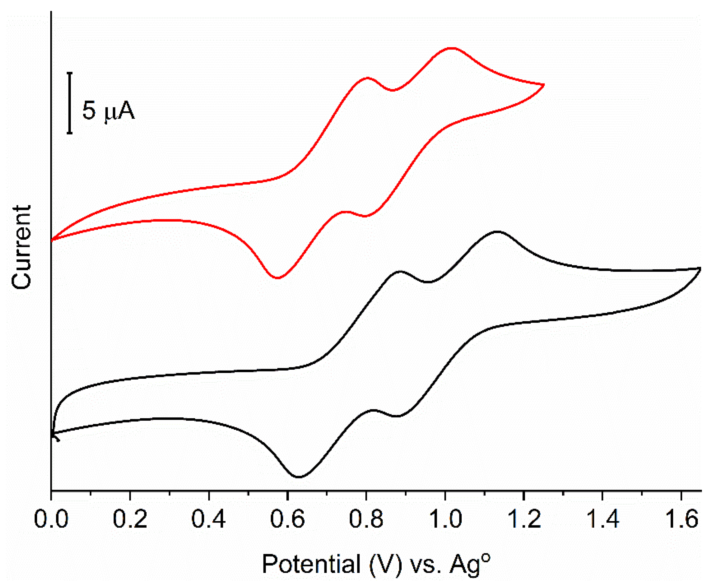
To investigate the electroactivity of poly-1 and its electrochromic properties, both its cyclic voltammetry and spectroelectrochemistry were examined. The film was electroactive, and it underwent two stepwise oxidations. Each process could be resolved at the scan speed of 100 mV/s, whereas the reverse waves for a similar derivative of 1 were found to be unresolvable at a slower scan rate [43,49]. The half-wave potentials (E1/2) of the film were +755 and +1010 mV vs. the pseudo-reference silver wire. The potentials were slightly more positive than 1 when it was measured in a solution. The monomer also underwent two stepwise oxidations of E1/2 = +685 mV and +900 mV (Figure 2).
Cyclic voltammetry confirmed that the film could be reversibly oxidized. The two observed processes were understood to be the radical cation and dication [56,57]. Both species were expected to have a unique color. Given the polymer film was transparent, its oxidation should give rise to visually detectable color changes. This was confirmed by spectroelectrochemistry (vide infra), which monitors the change in absorbance spectrum with applied potential.
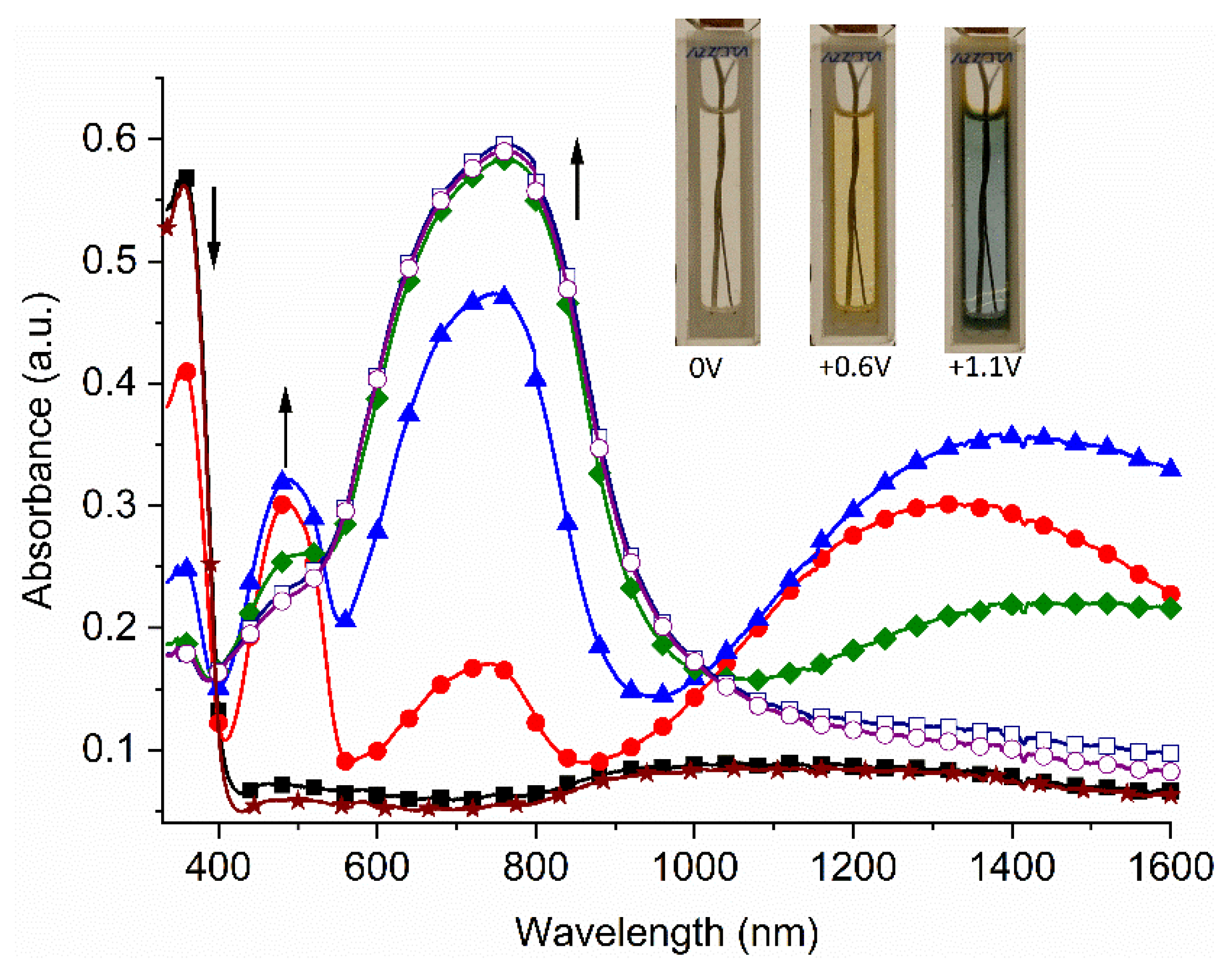
The neutral state of poly-1 had an absorption at 355 nm, consistent with it being colorless and highly transmissive in the visible region. The absorption in the UV region decreased with applied positive potentials upwards of 600 mV with the concomitant formation of three new absorption peaks. A potential less than the 1st oxidation potential was applied to observe the spectral changes that were exclusively from the first stepwise oxidation. Two discrete absorptions occurred at 485 nm and 760 nm. These were assigned to the radical cation and dication, respectively, according to the electrochemical data and previous doping studies of an analogue of 1 [43]. Meanwhile, a broad absorption in the NIR region occurred at ~1400 nm (Figure 3). The broad and featureless absorption is consistent with an intervalent charge transfer [58,59]. The perceived color of the film for the first oxidation step was yellow. The absorption in the UV region bleached upon increasing the applied potential to reach the second oxidation potential. The absorption at 760 nm also dominated the spectrum with the disappearance of the broad NIR absorption. The perceived color changed from yellow to blue when increasing the potential from the first oxidation potential to the second oxidation potential (inset Figure 3).
The spectroelectrochemistry of the corresponding monomer (1) was also examined. This was to frame the results of poly-1 and to determine the effect of immobilizing the electroactive compound as a thin film on the electrode. Given that 1 was soluble in the electrolyte solution for the spectroelectrochemical measurements, this precluded measuring its spectroelectrochemistry under the same conditions with the ITO working electrode as with poly-1. Instead, a thin ceramic 19-well honeycomb electrode was used as the working electrode. Similar changes in the absorption spectra and the perceived colors were observed for 1 in solution (Figure S14). The perceived colors of the neutral and the oxidized states were quantified by the CIE L*a*b* coordinates. Both the a* and b* parameters were close to 0. Meanwhile, the lightness L* value of ca. 100 confirmed the full transparency of the layer. At the first oxidation potential, the lightness decreased along with a change towards the red and yellow components, according to the increase in the a* and b* parameters. These confirmed the perceived yellow color. The lightness further decreased at the second redox potential along with the negative values in the a* and b* parameters. These confirmed the strong blue/green component to the color in the 360–800 nm spectral range. The same change in the color coordinates was also observed for 1. The similar L*a*b* coordinates of the different electrochemically mediated species of the thin film of poly-1 and 1 (Table S1), combined with the similar redox properties, confirm that immobilizing 1 as a cross-linked polymer film on the ITO electrode does not affect its electroactivity and its color.
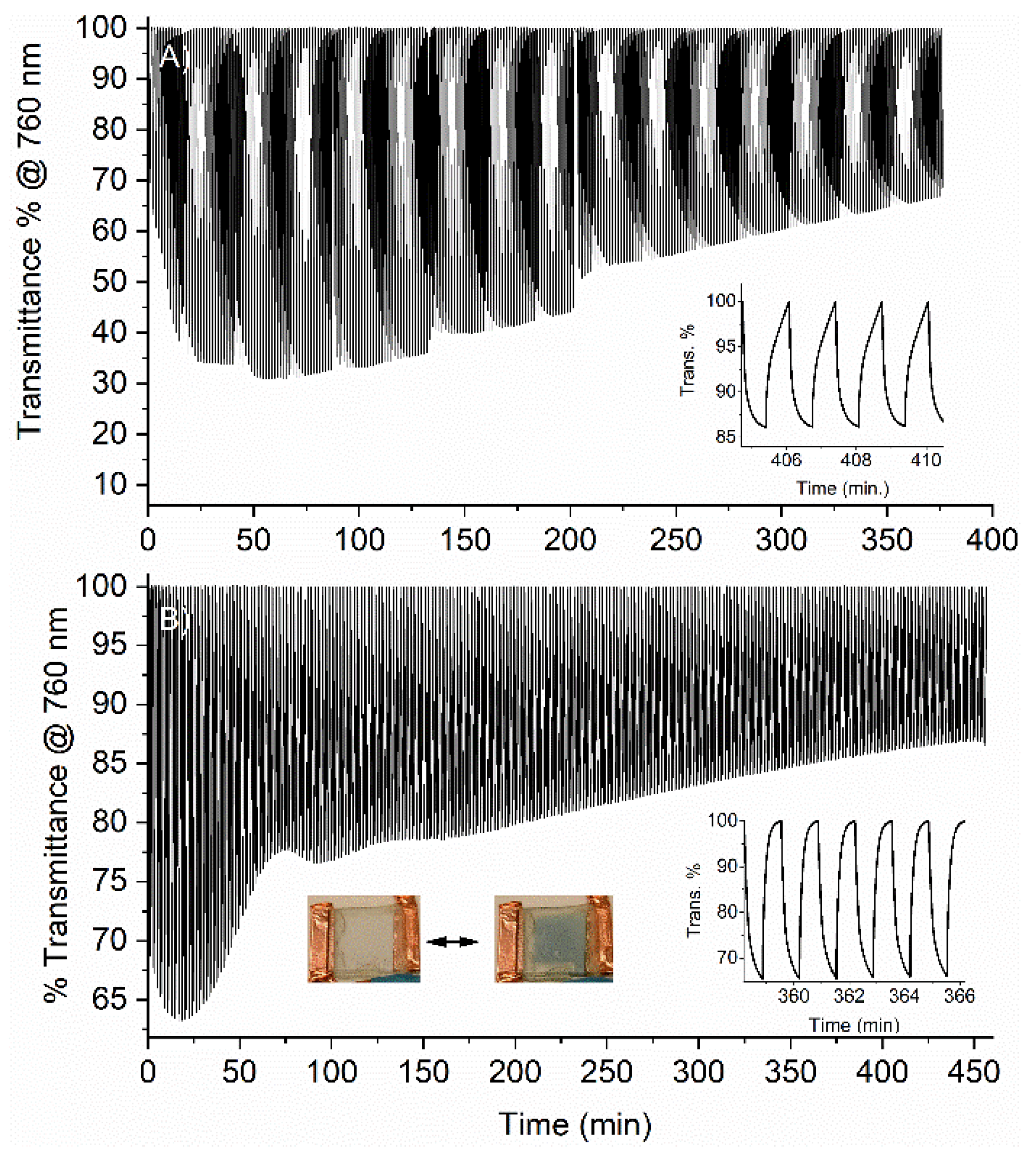
The spectroelectrochemical data confirm that poly-1 indeed had ideal properties for its use as an electrochromic layer in working devices; reversible electrochemistry and color changes with applied potential. Chronoabsorptometry was used to better assess its true electrochromic properties. This involved monitoring the change in the transmittance at a given wavelength when switching the applied potentials between the neutral and the oxidized states. The immobilized poly-1 was evaluated in a half-device configuration. This consisted of poly-1 immobilized as a thin film on the working ITO electrode, which was then immersed in the electrolyte solution of TBAPF6 in dichloromethane. The monitoring wavelength of 760 nm was selected because it was expected to give the highest transmittance difference when switching between the neutral and oxidized states. The potential was repeatedly switched between the second oxidation state of poly-1 by applying potentials of +1100 and −500 mV. The latter was selected to ensure that all the electrochemically oxidized produced states were reduced to the bleached state, resulting in a blue to complete colorless color change. The color change of poly-1 with applied potential is seen in the inset of Figure 3, where the entire film on the working electrode changes color. Its color bleached to the original colorless neutral state when the oxidized state was electrochemically reduced. The applied potentials were switched at 40 s intervals to ensure sufficient amounts of the oxidized states were formed to be spectroscopically detectable. Although the coloration efficiency cannot be calculated because the area of the working electrode could not be known exactly, the change in the maximum transmittance percentage (ΔT%) between the neutral (−500 mV) and oxidized states (+1100 mV) was ~70% for poly-1 in the half-device configuration. The polymer film could switch its color for over 380 min, during 285 complete oxidation/reduction cycles (Figure 4A). While the exact reason for the ~30% decrease in the transmittance difference overtime cannot be unequivocally assigned, the electroactive film could nonetheless sustain multiple oxidation/reduction cycles with applied potential switching leading to reversible color changes.
The transmittance difference switching behavior of poly-1 demonstrates its suitability as an electrochromic layer. A working sandwich device was therefore fabricated, and it was evaluated to test its true behavior in a functioning device over extended switching periods. The working device was prepared similarly to the half-device. With this single-layer device architecture, the color of the oxidized state can be maintained only when the applied potential is maintained. In the absence of an applied potential, the color of the oxidized state rapidly bleaches to the neutral state. The device was assessed by chronoabsorptometry by monitoring the transmittance difference at 760 nm with applied potential. Similar to the half-device, a large transmittance difference was observed when switching between the neutral and the oxidized states (Figure 4B). The potential required to induce the color change was greater than for the half-device. This was in part because no reference electrode was used with the full device. The difference in potential can also be assigned to variances in the intrinsic conductivities of the solution and the gel for the half- and full-device, respectively. This aside, the device could be repeatedly switched between its neutral and second oxidation states upwards of 450 min. Similar to the half-device, the entire layer of poly-1 in the device changed from colorless to blue with applied potential. While the transmittance difference decreased by 20% overtime, poly-1 could nonetheless be used as an electrochromic layer in a true working device for an extended period of time.
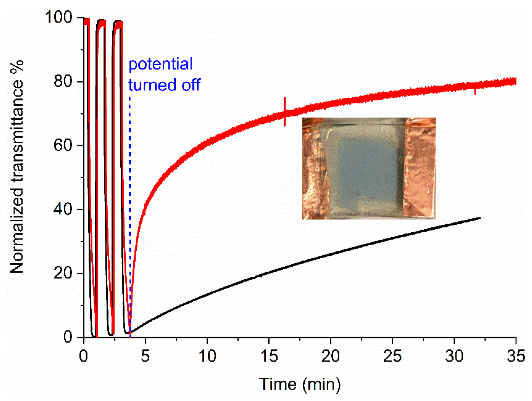
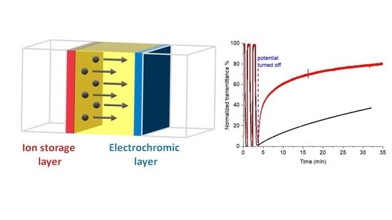
One layer acts as the charge storage for its complementary layer in a dual-layer device. In this configuration, the anodic and cathodic materials must have complementary oxidation and reduction potentials, respectively. This is the case with poly-1 and poly-2. Using poly-2 at the counter electrode, the blue color of the oxidized state of poly-1 should persist for longer periods than when poly-1 is uniquely used in a single-layer device. The double-layer sandwich device was therefore fabricated with poly-1 and poly-2 (Figure S17) to examine the extended color retention of the dual-layer device. A reference single-layer device was also fabricated with only poly-1 and using identical fabrication conditions with the same stock solution of 1. Both devices were first switched between their blue and colorless states for two complete cycles to condition the devices. This was in part to ensure that the color could be reversibly switched with applied potential. It was also to benchmark the transmittance percent difference between the two devices and to compare their capacity to maintain the switched color after the potential was no longer applied. As per Figure 5, the normalized transmittance percent difference for both devices was identical at 760 nm with the applied potential. To test their color memory, both devices were oxidized to their blue state for the same amount of time. The potential was then turned off and the transmittance was monitored over time. The transmittance of the single-layer device decreased by ~40% one minute after the potential was switched off. In contrast, the transmittance of the double-layer device decreased by only ~4% one minute after the potential was no longer applied. In fact, 60% of the color of the double-layer device was maintained upwards of 30 min without an applied potential. During the same time frame, more than 80% of the color of the oxidized stated for the single-layer device bleached. The color of the electrochemically generated state of the double-layer device therefore can be maintained for an extended period after once the potential is no longer applied, in contrast to its single-layer device counterpart. This proves that the addition of an ion-storage layer in the electrochromic device significantly increases its color retention in the absence of an applied potential. Moreover, immobilizing the electroactive layer as polymer films significantly reduces its diffusion. This further extends the colorfast of the oxidized state. Immobilizing the electroactive layers as polymer films also increases the duty cycle, with the device sustaining repeated cycles of switching the applied potentials and reversible color changes.

3. Materials and Methods

3.1. Electrochemistry

Electrochemical and spectroelectrochemical measurements were done similar to reported previously [60]. Platinum electrodes were used both as the working and auxiliary electrodes, while the pseudo-reference electrode was a polished silver wire.

3.2. Spectroelectrochemistry

Spectroelectrochemical measurements were done according to methods that were previously reported [60]. The spectroelectrochemistry of poly-1 was done after it was immobilized as a polymer film on a transparent ITO electrode. In this case, the ITO electrode was the working electrode and a platinum wire was the counter electrode with a silver wire pseudo-reference electrode. The electrochemically induced color changes of the layer were measured by switching between two redox states and monitoring the transmittance difference at 760 nm over time. The baseline was mathematically corrected by adjusted the transmittance at 760 nm of the neutral state to be consistently 100% over the course of the measurement. This was done to minimize the variations in the baseline that were a result from changes in the output of the spectrometer’s power supply. The correction did not change the absolute transmission difference between the two oxidation states.

3.3. Polymerization

The substrates (either glass microscopes coverslips or ITO glass) were sonicated in water and 2-propanol and then they were exposed to an UV-ozone atmosphere. A layer of either 2 with the addition of a small amount (~2% mol) of AIBN or 1 was obtained by spray-coating a stock solution on the ITO-coated glass slides [61]. The substrates were then heated in a glovebox under nitrogen at 110 °C for 1 and 90 °C for 2 for at least 1 h. The substrates were cooled and the resulting films were thoroughly rinsed with dichloromethane and the air dried to evaporate any residual solvent.

3.4. Film Thickness Measurements

The film thickness was measured with a stylus profilometer. The films were scored with a razor blade to expose the native surface. The film thickness was determined by scanning the height difference between the scored region and the polymer film over scans lengths of 2000 μm. Three different areas of the substrate were analysed to determine the average film thickness.

3.5. Device Fabrication

Transmissive sandwich-type devices were fabricated using ITO coated glass as the working electrodes. An electrolyte gel was prepared using the previously reported procedure [42]. Polyethylene glycol (20 kD) and LiClO4 were dissolved in 25% w/v acetonitrile to obtain a homogenous mixture. The solvent was then allowed to slowly evaporate at room temperature for 48 h. Double-sided adhesive tape was used to form a frame on the conductive side of either the ITO-coated glass slide (2 cm × 2 cm) or the ITO glass slide that was coated with poly-2. The gel electrolyte was then spread inside the frame. A second ITO-glass slide that was coated with a layer of the immobilized poly-1 was placed face down on the gel coated slide. The two electrodes were then pressed together. Any air bubbles that resulted when sandwiching the two electrodes together were removed before sealing the device. The device was subsequently sealed with a commercial 2-component epoxy that was applied to all sides of the device. This was to prevent oxygen and moisture from diffusing into the device. Sealing the device also prevented the two electrodes from delaminating during device operation.

3.6. Synthesis (See the Reaction Scheme in the Supporting Information for the Corresponding Numbering of the Compounds)

N4,N4,N4′,N4′-Tetraphenylbiphenyl-4,4′-diamine (3) [62,63]. To a solution of N4,N4′-diphenylbiphenyl-4,4′-diamine (1 g, 3 mmol) and iodobenzene (2.4 g, 11.8 mmol) in anhydrous toluene (30 mL) were added 1,10-phenantroline (107 mg, 0.6 mmol), copper(I) chloride (60 mg, 0.6 mmol) and potassium hydroxide (1.3 g, 23.2 mmol). The solution was stirred at 120 °C for 48 h. It was then cooled to room temperature; afterwards, water (50 mL) was slowly added. The organic phase was extracted with dichloromethane (3 × 30 mL). The combined organic fractions were dried over MgSO4, filtered, and the solvent was evaporated. The crude product was purified by column chromatography (SiO2, dichloromethane/hexane 1:9 v/v) to afford the product as a white solid (1.23 g, 85%). 1H NMR (400 MHz, CDCl3): δ 7.47 (d, J = 8.7 Hz, 4H), 7.29 (t, J = 7.4 Hz, 8H), 7.19-7.11 (m, 12H), 7.05 (t, J = 7.3 Hz, 4H) ppm. 13C NMR (100 MHz, CDCl3): δ 147.9, 146.9, 134.9, 129.4, 127.4, 124.4, 124.2, 122.9 ppm. HRMS m/z = [M+H]+ calcd. for C36H29N2 489.2325; found 489.2325.
4,4′-(Biphenyl-4,4′-diylbis(phenylazanediyl))dibenzaldehyde (4) [6,62]. A solution of 3 (0.7 g, 1.4 mmol) in anhydrous 1,2-dichloroethane (10 mL) and N,N-dimethylformamide (2.76 mL) was cooled to 0 °C. Slowly, POCl3 (3.45 mL) was added. Afterwards, the mixture was slowly warmed to room temperature. The mixture was then heated at 100 °C for 15 h, and then it was cooled to room temperature, neutralized with saturated NaHCO3 and extracted with dichloromethane (3 × 20 mL). The combined organic layer was dried over MgSO4 and the solvent was evaporated. The product was isolated as a yellow solid (650 mg, 81%) after purification by column chromatography (SiO2, CH2Cl2/hexane 8:2 v/v). 1H NMR (400 MHz, CDCl3) δ 9.83 (s, 2H), 7.71 (d, J = 8.9 Hz, 4H), 7.55 (d, J = 8.8 Hz, 4H), 7.40-7.32 (m, 4H), 7.26-7.16 (m, 10H), 7.08 (d, J = 8.7 Hz, 4H) ppm. 13C NMR (100 MHz, CDCl3) δ 190.6, 153.3, 146.2, 145.6, 136.8, 131.5, 130.0, 129.5, 128.1, 126.5, 126.3, 125.4, 119.9 ppm. HRMS m/z = [M+H]+ calcd. For C38H29N2O2 545.2224, found 545.2207.
(([1,1′-Biphenyl]-4,4′-diylbis(phenylazanediyl))bis(4,1-phenylene))dimethanol (5). A solution of 4 (0.45 g, 0.82 mmol) in anhydrous THF (20 mL) was cooled to 0 °C. Under a nitrogen atmosphere, NaBH4 (0.12 g, 3.3 mmol) was added portion-wise. The solution was slowly warmed to room temperature and it was stirred for 24 h. Water (30 mL) was slowly added to the mixture; afterwards, the organic phase was extracted with dichloromethane (3 × 30 mL). The organic layer was dried over MgSO4, filtered and the solvent was evaporated. The crude product was purified by column chromatography (SiO2, dichloromethane) to afford the product as a white solid (390 mg, 86%). 1H NMR (400 MHz, CDCl3): δ 7.45 (d, J = 8.7 Hz, 4H), 7.31-7.24 (m, 8H), 7.13 (d, J = 8.3 Hz, 12H), 7.04 (t, J = 7.3 Hz, 2H), 4.66 (s, 4H) ppm. 13C NMR (100 MHz, CDCl3): δ 147.7, 147.5, 146.8, 135.3, 135.0, 129.4, 128.4, 127.5, 124.5, 124.3, 124.3, 123.1, 65.2 ppm. HRMS m/z = [M+H]+ calcd. for C38H33N2O2 549.2537; found 549.2536.
N4,N4′-Diphenyl-N4,N4′-bis(4-(((4-vinylbenzyl)oxy)methyl)phenyl)-[1,1′-biphenyl]-4,4′-diamine (1). A solution of 5 (0.2 mg, 0.36 mmol) in anhydrous DMF (5 mL) was cooled to 0 °C. To this was added sodium hydride (60% in mineral oil; 60 mg, 1.46 mmol). The mixture was stirred at 0 °C for 30 min and 1-(chloromethyl)-4-vinylbenzene (0.17 g, 1.1 mmol) was then added dropwise. The solution was stirred at room temperature for 24 h. Afterwards, water (30 mL) and dichloromethane (30 mL) were added to the mixture. The organic phase was extracted with dichloromethane (3 × 30 mL), dried over MgSO4 and then filtered. The solvent was evaporated and the crude product was purified by column chromatography (SiO2, dichloromethane/hexane 6:4 v/v) to afford the title compound as a white solid (250 mg, 88%). 1H NMR (400 MHz, CDCl3): δ 7.49 (d, J = 8.6 Hz, 4H), 7.46 (d, J = 8.2 Hz, 4H), 7.40 (d, J = 8.2 Hz, 4H), 7.30 (m, 8H), 7.19-7.15 (m, 12H), 7.07 (t, J = 7.3 Hz, 2H), 6.77 (dd, J = 17.6, 10.9 Hz, 2H), 5.81 (dd, J = 17.6, 0.8 Hz, 2H), 5.29 (dd, J = 10.9, 0.8 Hz, 2H), 4.63 (s, 4H), 4.54 (s, 4H) ppm. 13C NMR (100 MHz, CDCl3): δ 147.7, 147.3, 146.7, 138.0, 137.1, 136.6, 134.9, 132.6, 129.4, 129.2, 128.1, 127.4, 126.4, 124.4, 124.2, 123.0, 113.9, 72.0, 71.9 ppm. HRMS m/z = [M+H]+ calcd. for C56H49N2O2 781.3789, found 781.3763.
1,1′-Bis(4-vinylbenzyl)-4,4′-bipyridine-1,1′-diium hexafluorophosphate(V) (2) [64]. A solution of 4,4′-bipyridine (0.25 g, 1.6 mmol) and 1-(chloromethyl)-4-vinylbenzene (0.97 g, 6.4 mmol) in acetonitrile (3 mL) was placed in a microwaveable pressure tube after degassing with nitrogen. It was sealed and then heated at 135 °C for 10 min in a microwave reactor. The yellow solid was filtered, solubilized in water and a solution of NH4PF6 (2.61 g, 16.0 mmol) was then added. The mixture was stirred for 30 min, and the resulting solid was filtered. The title compound was obtained as a slightly pink solid (960 mg, 88%) after recrystallizing from water. 1H NMR (400 MHz, MeOD): δ 9.36 (d, J = 7.0 Hz, 4H), 8.70 (d, J = 6.8 Hz, 4H), 7.59 (s, 8H), 6.79 (dd, J = 17.6, 10.9 Hz, 2H), 5.99 (s, 4H), 5.88 (dd, J = 17.6, 0.6 Hz, 2H), 5.35 (dd, J = 11.0, 0.5 Hz, 2H) ppm. 13C NMR (100 MHz, MeOD): δ 151.6, 147.0, 140.9, 137.0, 133.5, 130.7, 128.6, 128.4, 116.1, 65.6 ppm. HRMS m/z = [M-PF6]+ calcd. for C28H26N2(PF6)2 535.1723; found 535.1722.

4. Conclusions

Robustly immobilized electroactive layers could be obtained by thermally annealing the corresponding monomer on ITO coated glass substrates. No difference in the redox and the spectroelectrochemical properties was observed between the polymerized thin films and its solution soluble counterpart. The benefits of immobilizing the electroactive layer were prolonged electrochromic duty cycle with upwards of 250 colorless-to-colored cycles and extended colorfast being observed. Little color fading occurred in both the half- and the full-electrochromic devices, during 6 h of electrochemical switching. The addition of a complementary electroactive layer improved the device performance by preserving the colorfast of the oxidized state once the potential was no longer applied. Dual-layer devices consisting of complementary anodic and cathodic layers therefore have the potential to consume less energy by maintaining their colored state without an applied potential compared to their single-layer device counterparts. Meanwhile, the straightforward deposition and thermal annealing of the electroactive layers are potentially amenable to large-area and large-scale processing.

Supplementary Materials

The following are available online at https://www.mdpi.com/2673-3978/1/1/5/s1, Figure S1: Synthetic scheme for the preparation of 1, Figure S2: Synthetic scheme for the preparation of 2, Figure S3: TGA analysis of 1, Figure S4: TGA analysis of 2, Figure S5: DSC analysis of 1, Figure S6: DSC analysis of 2, Figure S7: The FT-IR spectra of 1 before (black) and after polymerization (red), Figure S8: The FT-IR spectra of 2 before (black) and after polymerization (red), Figure S9: Profilometry traces of a spin coated thin film of 1 before (red) and after (black) polymerization, Figure S10: Profilometry traces of a spin coated thin film of 2 before (red) and after (black) polymerization, Figure S11: Complete cyclic voltammogram of 2 measured in anhydrous and deaerated dichloromethane with 0.1 M TBAPF6 and calibrated against ferrocene (Eo = 0.46 V vs. SCE) at 100 mV/s, Figure S12: Cathodic cyclic voltammogram of poly-2 measured in anhydrous and deaerated dichloromethane with 0.1 M TBAPF6 at 100 mV/s, Figure S13: Anodic cyclic voltammograms (30 cycles) of 1 measured in anhydrous and deaerated dichloromethane with 0.1 M TBAPF6 at 100 mV/s, Figure S14: Spectroelectrochemistry of 1 measured in anhydrous and deaerated dichloromethane with TBAPF6 as an electrolyte with applied potentials of 0 (■), 400 (), 500 (), 600 (), 700 (), 800 (), 900 (), 1000 (), 1100 (*) and −300 () mV held for 30 s per potential. Insert: photographs of original neutral, first oxidation (700 mV), second oxidation (1100 mV), and reduced (−300 mV) states of 1 with applied potential of 1 min., Figure S15: CIE L*a*b*color coordinates of a film of poly-1 in its neutral (black), 1st oxidation (red) and 2nd oxidation (blue) states, Figure S16: Absorbance spectra of the dual-layer electrochromic device consisting of poly-1 and poly-2 with the electrolytic gel in its neutral (■) and oxidized () states, Figure S17: Change in transmittance percent of the double layer electrochromic device with poly-1 and poly-2 monitored at 760 nm as a function of switching potentials between +3300 and −2000 mV at 40 sec intervals. Baseline at 100% of transmittance was corrected to be consistent over time. Inserts: photographs of the double layer electrochromic device in the neutral (left) and oxidized states (right), Figure S18: 1H NMR spectrum of 3 in CDCl3, Figure S19: 13C NMR spectrum of 3 in CDCl3, Figure S20: 1H NMR spectrum of 4 in CDCl3, Figure S21: 13C NMR spectrum of 4 in CDCl3, Figure S22: 1H NMR spectrum of 5 in CDCl3, Figure S23: 13C NMR spectrum of 5 in CDCl3, Figure S24: 1H NMR spectrum of 1 in CDCl3, Figure S25: 13C NMR spectrum of 1 in CDCl3, Figure S26: 1H NMR spectrum of 2 in MeOD, Figure S27: 13C NMR spectrum of 2 in MeOD. Table S1: CIE coordinates with A, B and C illuminants with the 2° standard observer angle of poly-1.

Author Contributions

Conceptualization, M.W.-C., W.G.S; methodology, M.W.-C.; validation, M.W.-C., W.G.S.; formal analysis, M.W.-C.; investigation, M.W.-C.; resources, W.G.S; data curation, M.W.-C., W.G.S.; writing—original draft preparation, M.W.-C., W.G.S.; writing—review and editing, M.W.-C., W.G.S.; visualization, M.W.-C.; project administration, M.W.-C., W.G.S.; funding acquisition, W.G.S. All authors have read and agreed to the published version of the manuscript.

Funding

This research was funded by the Natural Sciences and Engineering Council of Canada (NSERC) via Discovery and I2IB research grants. The Canada Foundation for Innovation (CFI) is also acknowledged for equipment and infrastructure that enabled this work.

Acknowledgments

The former Center for Self-Assembled Chemical Structures and the Quebec Centre for Advanced Materials are acknowledged for access to infrastructure and equipment that were used for the reported measurements.

Conflicts of Interest

There are no conflict to declare.

References

  1. Yen, H.-J.; Liou, G.-S. Recent Advances in Triphenylamine-Based Electrochromic Derivatives and Polymers. Polym. Chem. 2018, 9, 3001–3018. [Google Scholar] [CrossRef]
  2. Hsiao, S.-H.; Liao, W.-K.; Liou, G.-S. A Comparative Study of Redox-Active, Ambipolar Electrochromic Triphenylamine-Based Polyimides Prepared by Electrochemical Polymerization and Conventional Polycondensation Methods. Polym. Chem. 2018, 9, 236–248. [Google Scholar] [CrossRef]
  3. Hsiao, S.-H.; Chen, Y.-Z. Electroactive and Ambipolar Electrochromic Polyimides from Arylene Diimides with Triphenylamine N-Substituents. Dye Pigment 2017, 144, 173–183. [Google Scholar] [CrossRef]
  4. Huang, Q.; Evmenenko, G.A.; Dutta, P.; Lee, P.; Armstrong, N.R.; Marks, T.J. Covalently Bound Hole-Injecting Nanostructures. Systematics of Molecular Architecture, Thickness, Saturation, and Electron-Blocking Characteristics on Organic Light-Emitting Diode Luminance, Turn-on Voltage, and Quantum Efficiency. J. Am. Chem. Soc. 2005, 127, 10227–10242. [Google Scholar] [CrossRef]
  5. Huang, Q.; Evmenenko, G.; Dutta, P.; Marks, T.J. Molecularly “Engineered” Anode Adsorbates for Probing OLED Interfacial Structure-Charge Injection/Luminance Relationships:  Large, Structure-Dependent Effects. J. Am. Chem. Soc. 2003, 125, 14704–14705. [Google Scholar] [CrossRef]
  6. Zhao, X.; Wang, S.; You, J.; Zhang, Y.; Li, X. Solution-Processed Thermally Stable Amorphous Films of Small Molecular Hole Injection/Transport Bi-Functional Materials and Their Application in High Efficiency OLEDs. J. Mater. Chem. C 2015, 3, 11377–11384. [Google Scholar] [CrossRef]
  7. Yuan, W.Z.; Gong, Y.; Chen, S.; Shen, X.Y.; Lam, J.W.Y.; Lu, P.; Lu, Y.; Wang, Z.; Hu, R.; Xie, N.; et al. Efficient Solid Emitters with Aggregation-Induced Emission and Intramolecular Charge Transfer Characteristics: Molecular Design, Synthesis, Photophysical Behaviors, and OLED Application. Chem. Mater. 2012, 24, 1518–1528. [Google Scholar] [CrossRef]
  8. Yuan, W.Z.; Lu, P.; Chen, S.; Lam, J.W.Y.; Wang, Z.; Liu, Y.; Kwok, H.S.; Ma, Y.; Tang, B.Z. Changing the Behavior of Chromophores from Aggregation-Caused Quenching to Aggregation-Induced Emission: Development of Highly Efficient Light Emitters in the Solid State. Adv. Mater. 2010, 22, 2159–2163. [Google Scholar] [CrossRef] [PubMed]
  9. Kimura, M.; Kuwano, S.; Sawaki, Y.; Fujikawa, H.; Noda, K.; Taga, Y.; Takagi, K. New 9-Fluorene-Type Trispirocyclic Compounds for Thermally Stable Hole Transport Materials in OLEDs. J. Mater. Chem. 2005, 15, 2393–2398. [Google Scholar] [CrossRef]
  10. Bacher, E.; Bayerl, M.; Rudati, P.; Reckefuss, N.; Müller, C.D.; Meerholz, K.; Nuyken, O. Synthesis and Characterization of Photo-Cross-Linkable Hole-Conducting Polymers. Macromolecules 2005, 38, 1640–1647. [Google Scholar] [CrossRef]
  11. Liu, X.; Zhu, L.; Zhang, F.; You, J.; Xiao, Y.; Li, D.; Wang, S.; Meng, Q.; Li, X. Stable Perovskite Solar Cells based on Hydrophobic Triphenylamine Hole-Transport Materials. Energy Technol. 2017, 5, 312–320. [Google Scholar] [CrossRef]
  12. Song, Y.; Lv, S.; Liu, X.; Li, X.; Wang, S.; Wei, H.; Li, D.; Xiao, Y.; Meng, Q. Energy Level Tuning of TPB-Based Hole-Transporting Materials for Highly Efficient Perovskite Solar Cells. Chem. Commun. 2014, 50, 15239–15242. [Google Scholar] [CrossRef] [PubMed]
  13. Zhao, X.; Liu, T.; Zhang, Y.; Wang, S.; Li, X.; Xiao, Y.; Hou, X.; Liu, Z.; Shi, W.; Dennis, T.J.S. Organic Single-Crystalline Donor–Acceptor Heterojunctions with Ambipolar Band-Like Charge Transport for Photovoltaics. Adv. Mater. Interfaces 2018, 5, 1800336. [Google Scholar] [CrossRef]
  14. Yen, H.-J.; Liou, G.-S. Design and Preparation of Triphenylamine-Based Polymeric Materials towards Emergent Optoelectronic Applications. Prog. Polym. Sci. 2019, 89, 250–287. [Google Scholar] [CrossRef]
  15. Jarosz, T.; Gebka, K.; Stolarczyk, A.; Domagala, W. Transparent to Black Electrochromism—The “Holy Grail” of Organic Optoelectronics. Polymers 2019, 11, 273. [Google Scholar] [CrossRef] [PubMed] [Green Version]
  16. Santra, D.C.; Nad, S.; Malik, S. Electrochemical Polymerization of Triphenylamine End-Capped Dendron: Electrochromic and Electrofluorochromic Switching Behaviors. J. Electroanal. Chem. 2018, 823, 203–212. [Google Scholar] [CrossRef]
  17. Ji, L.; Dai, Y.; Yan, S.; Lv, X.; Su, C.; Xu, L.; Lv, Y.; Ouyang, M.; Chen, Z.; Zhang, C. A Fast Electrochromic Polymer Based on TEMPO Substituted Polytriphenylamine. Sci. Rep. 2016, 6, 30068. [Google Scholar] [CrossRef]
  18. Moon, H.C.; Kim, C.-H.; Lodge, T.P.; Frisbie, C.D. Multicolored, Low-Power, Flexible Electrochromic Devices Based on Ion Gels. ACS Appl. Mater. Interfaces 2016, 8, 6252–6260. [Google Scholar] [CrossRef]
  19. Gélinas, B.; Das, D.; Rochefort, D. Air-Stable, Self-Bleaching Electrochromic Device Based on Viologen- and Ferrocene-Containing Triflimide Redox Ionic Liquids. ACS Appl. Mater. Interfaces 2017, 9, 28726–28736. [Google Scholar] [CrossRef]
  20. Ho, K.-C.; Lu, H.-C.; Yu, H.-F. Chapter 12 Viologens-based Electrochromic Materials and Devices. In Electrochromic Smart Materials: Fabrication and Applications; Xu, J.W., Chua, M.H., Shah, K.W., Eds.; The Royal Society of Chemistry: London, UK, 2019; pp. 372–405. [Google Scholar]
  21. Granqvist, C.-G. Out of a Niche. Nat. Mater. 2006, 5, 89–90. [Google Scholar] [CrossRef]
  22. Heusing, S.; Aegerter, M.A. Sol-Gel Coatings for Electrochromic Devices. In Handbook of Sol-Gel Science and Technology; Klein, L., Aparicio, M., Jitianu, A., Eds.; Springer International Publishing: Cham, Switzerland, 2016; pp. 1–49. [Google Scholar]
  23. Eh, A.L.-S.; Tan, A.W.M.; Cheng, X.; Magdassi, S.; Lee, P.S. Recent Advances in Flexible Electrochromic Devices: Prerequisites, Challenges, and Prospects. Energy Technol. 2018, 6, 33–45. [Google Scholar] [CrossRef]
  24. Liu, H.-S.; Pan, B.-C.; Huang, D.-C.; Kung, Y.-R.; Leu, C.-M.; Liou, G.-S. Highly Transparent to Truly Black Electrochromic Devices Based on an Ambipolar System of Polyamides and Viologen. NPG Asia Mater. 2017, 9, e388. [Google Scholar] [CrossRef]
  25. Wu, J.-T.; Lin, H.-T.; Liou, G.-S. Synthesis and Characterization of Novel Triarylamine Derivatives with Dimethylamino Substituents for Application in Optoelectronic Devices. ACS Appl. Mater. Interfaces 2019, 11, 14902–14908. [Google Scholar] [CrossRef] [PubMed]
  26. Zhuang, Y.; Zhao, W.; Wang, L.; Li, F.; Wang, W.; Liu, S.; Huang, W.; Zhao, Q. Soluble Triarylamine Functionalized Symmetric Viologen for all-solid-state electrochromic supercapacitors. Sci. China Chem. 2020, 63, 1632–1644. [Google Scholar] [CrossRef]
  27. Cospito, S.; De Simone, B.C.; Beneduci, A.; Imbardelli, D.; Chidichimo, G. Novel Electrochromic Gel with High Optical Contrast in the Visible and Near-Infrared. Mater. Chem. Phys. 2013, 140, 431–434. [Google Scholar] [CrossRef]
  28. Madasamy, K.; Velayutham, D.; Suryanarayanan, V.; Kathiresan, M.; Ho, K.-C. Viologen-Based Electrochromic Materials and Devices. J. Mater. Chem. C 2019, 7, 4622–4637. [Google Scholar] [CrossRef]
  29. Ding, J.; Zheng, C.; Wang, L.; Lu, C.; Zhang, B.; Chen, Y.; Li, M.; Zhai, G.; Zhuang, X. Viologen-Inspired Functional Materials: Synthetic Strategies and Applications. J. Mater. Chem. A 2019, 7, 23337–23360. [Google Scholar] [CrossRef]
  30. Hua, C.; Chan, B.; Rawal, A.; Tuna, F.; Collison, D.; Hook, J.M.; D’Alessandro, D.M. Redox Tunable Viologen-Based Porous Organic Polymers. J. Mater. Chem. C 2016, 4, 2535–2544. [Google Scholar] [CrossRef] [Green Version]
  31. Lei, L.; Yang, S.; Zheng, J.; Xu, C. Electrochromic Device Based on Adsorbable Viologens. Acta Chim. Sin. 2014, 72, 456–460. [Google Scholar] [CrossRef] [Green Version]
  32. Yen, H.-J.; Tsai, C.-L.; Chen, S.-H.; Liou, G.-S. Electrochromism and Nonvolatile Memory Device Derived from Triphenylamine-Based Polyimides with Pendant Viologen Units. Macromol. Rapid Commun. 2017, 38, 1600715. [Google Scholar] [CrossRef]
  33. Weng, D.; Shi, Y.; Zheng, J.; Xu, C. High Performance Black-to-Transmissive Electrochromic Device with Panchromatic Absorption Based on TiO2-Supported Viologen and Triphenylamine Derivatives. Org. Electron. 2016, 34, 139–145. [Google Scholar] [CrossRef]
  34. Li, M.; Wei, Y.; Zheng, J.; Zhu, D.; Xu, C. Highly Contrasted and Stable Electrochromic Device Based on Well-Matched Viologen and Triphenylamine. Org. Electron. 2014, 15, 428–434. [Google Scholar] [CrossRef]
  35. Ah, C.S.; Song, J.; Cho, S.M.; Kim, T.-Y.; Ryu, H.; Cheon, S.; Kim, J.Y.; Hwang, C.-S.; Kim, Y.-H. Optical and Electrical Properties of Electrochromic Devices Depending on Electrolyte Concentrations and Cell Gaps. Bull. Korean Chem. Soc. 2016, 37, 1812–1819. [Google Scholar] [CrossRef]
  36. Rauh, R.D. Electrochromic Windows: An Overview. Electrochim. Acta 1999, 44, 3165–3176. [Google Scholar] [CrossRef]
  37. Zuniga, C.A.; Barlow, S.; Marder, S.R. Approaches to Solution-Processed Multilayer Organic Light-Emitting Diodes Based on Cross-Linking. Chem. Mater. 2010, 23, 658–681. [Google Scholar] [CrossRef]
  38. Kim, S.; Jin, X.; Tanaka, A.; Nagamura, T. High Contrast and Dynamic Electrochromic Display with Thin Solid Hyper-Branched Polymer Film. Mol. Crystal Liq. Cryst. 2011, 539, 5–10. [Google Scholar] [CrossRef]
  39. Kao, S.-Y.; Lu, H.-C.; Kung, C.-W.; Chen, H.-W.; Chang, T.-H.; Ho, K.-C. Thermally Cured Dual Functional Viologen-Based All-in-One Electrochromic Devices with Panchromatic Modulation. ACS Appl. Mater. Interfaces 2016, 8, 4175–4184. [Google Scholar] [CrossRef]
  40. Lee, J.; Lee, Y.; Ahn, J.; Kim, J.; Yoon, S.; Kim, Y.S.; Cho, K.Y. Improved Electrochromic Device Performance from Silver Grid on Flexible Transparent Conducting Electrode Prepared by Electrohydrodynamic Jet Printing. J. Mater. Chem. C 2017, 5, 566022. [Google Scholar] [CrossRef]
  41. Lu, H.-C.; Kao, S.-Y.; Chang, T.-H.; Kung, C.-W.; Ho, K.-C. An Electrochromic Device Based on Prussian Blue, Self-immobilized Vinyl Benzyl Viologen, and Ferrocene. Sol. Energy Mater. Sol. Cells 2016, 147, 75–84. [Google Scholar] [CrossRef]
  42. Wałęsa-Chorab, M.; Skene, W.G. Visible-to-NIR Electrochromic Device Prepared from a Thermally Polymerizable Electroactive Organic Monomer. ACS Appl. Mater. Interfaces 2017, 9, 21524–21531. [Google Scholar] [CrossRef]
  43. Sun, Y.; Chien, S.-C.; Yip, H.-L.; Zhang, Y.; Chen, K.-S.; Zeigler, D.F.; Chen, F.-C.; Lin, B.; Jen, A.K.Y. Chemically Doped and Cross-linked Hole-Transporting Materials as an Efficient Anode Buffer Layer for Polymer Solar Cells. Chem. Mater. 2011, 23, 5006–5015. [Google Scholar] [CrossRef]
  44. Monnier, F.; Taillefer, M. Catalytic C-C, C-N, and C-O Ullmann-Type Coupling Reactions. Angew. Chem. Int. Ed. 2009, 48, 6954–6971. [Google Scholar] [CrossRef] [PubMed]
  45. Sung, S.; Sale, D.; Braddock, D.C.; Armstrong, A.; Brennan, C.; Davies, R.P. Mechanistic Studies on the Copper-Catalyzed N-Arylation of Alkylamines Promoted by Organic Soluble Ionic Bases. ACS Catal. 2016, 6, 3965–3974. [Google Scholar] [CrossRef] [Green Version]
  46. Gawande, M.B.; Shelke, S.N.; Zboril, R.; Varma, R.S. Microwave-Assisted Chemistry: Synthetic Applications for Rapid Assembly of Nanomaterials and Organics. Acc. Chem. Res. 2014, 47, 1338–1348. [Google Scholar] [CrossRef]
  47. Janoschka, T.; Morgenstern, S.; Hiller, H.; Friebe, C.; Wolkersdorfer, K.; Haupler, B.; Hager, M.D.; Schubert, U.S. Synthesis and Characterization of TEMPO- and Viologen-Polymers for Water-Based Redox-Flow Batteries. Polym. Chem. 2015, 6, 7801–7811. [Google Scholar] [CrossRef]
  48. Liu, J.; Tan, C.S.Y.; Scherman, O.A. Dynamic Interfacial Adhesion through Cucurbit[n]uril Molecular Recognition. Angew. Chem. Int. Ed. 2018, 57, 8854–8858. [Google Scholar] [CrossRef] [Green Version]
  49. Cheng, Y.-J.; Liu, M.S.; Zhang, Y.; Niu, Y.; Huang, F.; Ka, J.-W.; Yip, H.-L.; Tian, Y.; Jen, A.K.Y. Thermally Cross-Linkable Hole-Transporting Materials on Conducting Polymer: Synthesis, Characterization, and Applications for Polymer Light-Emitting Devices. Chem. Mater. 2008, 20, 413–422. [Google Scholar] [CrossRef]
  50. Niu, Y.H.; Munro, A.M.; Cheng, Y.J.; Tian, Y.Q.; Liu, M.S.; Zhao, J.L.; Bardecker, J.A.; Jen-La Plante, I.; Ginger, D.S.; Jen, A.K.Y. Improved Performance from Multilayer Quantum Dot Light-Emitting Diodes via Thermal Annealing of the Quantum Dot Layer. Adv. Mater. 2007, 19, 3371–3376. [Google Scholar] [CrossRef]
  51. Sun, Y.; Gong, X.; Hsu, B.B.Y.; Yip, H.-L.; Jen, A.K.-Y.; Heeger, A.J. Solution-Processed Cross-Linkable Hole Selective Layer for Polymer Solar Cells in the Inverted Structure. Appl. Phys. Lett. 2010, 97, 193310. [Google Scholar] [CrossRef]
  52. Mayo, F.R. The dimerization of styrene. J. Am. Chem. Soc. 1968, 90, 1289–1295. [Google Scholar] [CrossRef]
  53. Abraham, S.; Mangalath, S.; Sasikumar, D.; Joseph, J. Transmissive-to-Black Electrochromic Devices Based on Cross-Linkable Tetraphenylethene-Diphenylamine Derivatives. Chem. Mater. 2017, 29, 9877–9881. [Google Scholar] [CrossRef]
  54. Monthéard, J.-P.; Camps, M.; Chatzopoulos, M.; Pham, Q.-T. A New Convenient Synthesis of Ortho-, Meta- and Para-Chloromethylstyrenes. Makromol. Chem. Phys. 1985, 186, 2513–2518. [Google Scholar] [CrossRef]
  55. Hsu, C.-Y.; Zhang, J.; Sato, T.; Moriyama, S.; Higuchi, M. Black-to-Transmissive Electrochromism with Visible-to-Near-Infrared Switching of a Co (II)-Based Metallo-Supramolecular Polymer for Smart Window and Digital Signage Applications. ACS Appl. Mater. Interfaces 2015, 7, 18266–18272. [Google Scholar] [CrossRef] [PubMed]
  56. Seo, E.T.; Nelson, R.F.; Fritsch, J.M.; Marcoux, L.S.; Leedy, D.W.; Adams, R.N. Anodic Oxidation Pathways of Aromatic Amines. Electrochemical and Electron Paramagnetic Resonance Studies. J. Am. Chem. Soc. 1966, 88, 3498–3503. [Google Scholar] [CrossRef]
  57. Rybakiewicz, R.; Zagorska, M.; Pron, A. Triphenylamine-Based Electroactive Compounds: Synthesis, Properties and Application to Organic Electronics. Chem. Pap. 2017, 71, 243–268. [Google Scholar] [CrossRef]
  58. Szeghalmi, A.V.; Erdmann, M.; Engel, V.; Schmitt, M.; Amthor, S.; Kriegisch, V.; Nöll, G.; Stahl, R.; Lambert, C.; Leusser, D.; et al. How Delocalized Is N,N,N′,N′-Tetraphenylphenylenediamine Radical Cation? An Experimental and Theoretical Study on the Electronic and Molecular Structure. J. Am. Chem. Soc. 2004, 126, 7834–7845. [Google Scholar] [CrossRef] [PubMed]
  59. Hsiao, S.-H.; Wang, H.-M.; Liao, S.-H. Redox-Stable and Visible/Near-Infrared Electrochromic Aramids with Main-Chain Triphenylamine and Pendent 3,6-di-tert-Butylcarbazole Units. Polym. Chem. 2014, 5, 2473–2483. [Google Scholar] [CrossRef]
  60. Wałęsa-Chorab, M.; Yao, C.; Tuner, G.; Skene, W.G. Electrochemical and Solvent Mediated Visible-to-Near Infrared Spectroscopic Switching of Benzoselenodiazole Fluorophores. Chem. Eur. J. 2020. [Google Scholar] [CrossRef]
  61. Wałęsa-Chorab, M.; Skene, W.G. Engaging the Reversible Bonds of an Immobilized Styreno-Thiophene Film. Cryst. Growth Des. 2020, 20, 5688–5697. [Google Scholar] [CrossRef]
  62. Bao, L.Q.; Phuong, H.; Thuy, C.T.T.; Lee, J.W.; Kim, J.H.; Thogiti, S. Synthesis and Investigation of Triphenylamine-Based Double Branched Organic Dyes for p-Type Dye-Sensitized Solar Cells. Mol. Cryst. Liq. Cryst. 2017, 653, 109–117. [Google Scholar] [CrossRef]
  63. Shin, W.S.; Kim, S.C.; Lee, E.-J.; Park, S.-M.; Jin, S.-H.; Lee, J.W.; Gal, Y.-S. Introduction of Interlayer via Oxetane Based Crosslinking Method for Blue Polymer Light-Emitting Diode Applications. Mol. Cryst. Liq. Cryst. 2007, 471, 335–343. [Google Scholar] [CrossRef]
  64. Liu, X.; Neoh, K.G.; Zhao, L.; Kang, E.T. Surface Functionalization of Glass and Polymeric Substrates via Graft Copolymerization of Viologen in an Aqueous Medium. Langmuir 2002, 18, 2914–2921. [Google Scholar] [CrossRef]
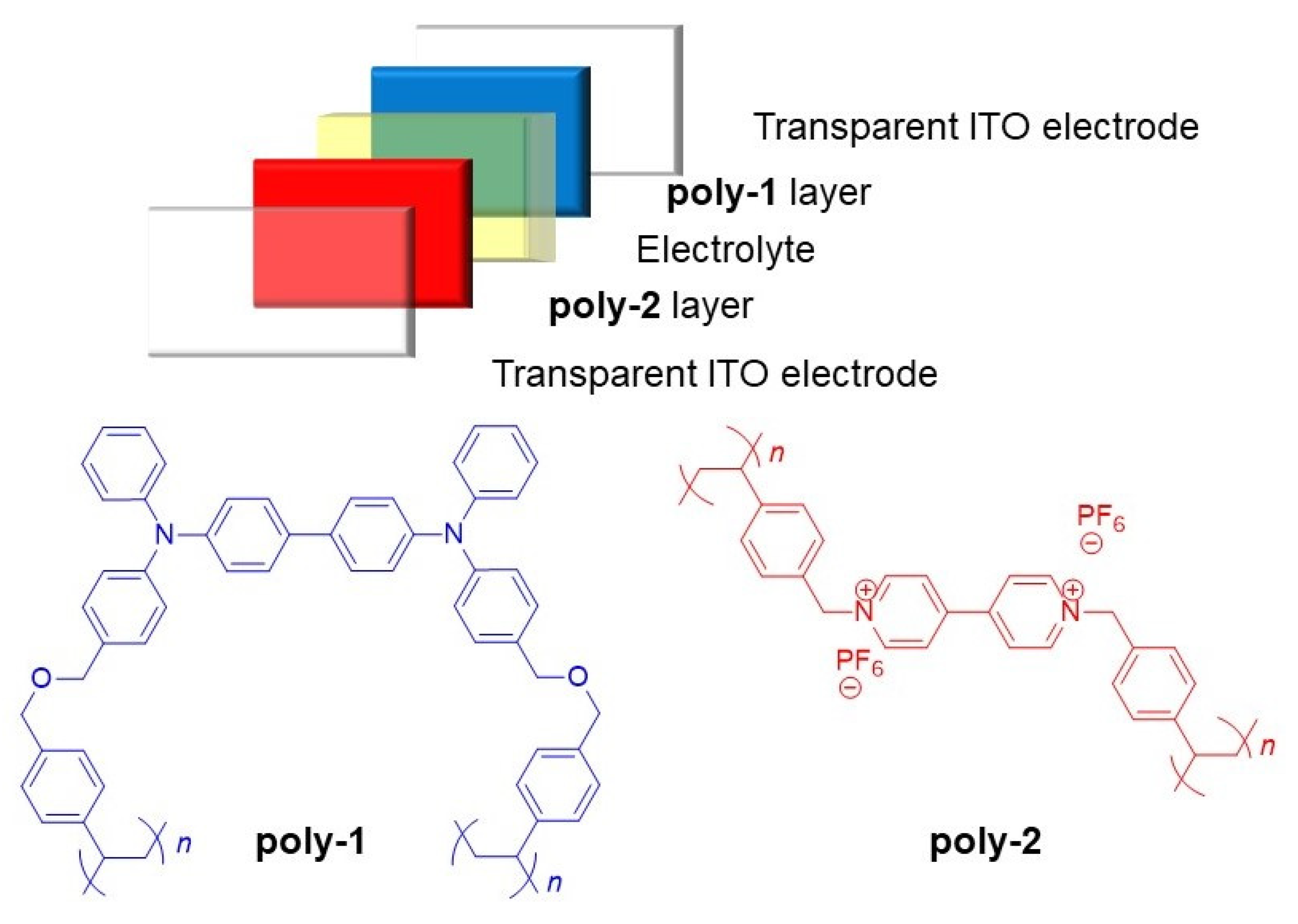
Figure 1. Schematic representation of the electrochromic device consisting of the electrochromic (poly-1) and ion storage (poly-2) layers. The layers of the device are arbitrarily colored for visual purposes only and to correlate with the represented polymer structures.
Electronicmat 01 00005 g001
Figure 2. Anodic cyclic voltammograms of 1 () dissolved in dichloromethane and poly-1 immobilized on a transparent ITO electrode (▬) measured in anhydrous and deaerated dichloromethane with 0.1 M TBAPF6 as an electrolyte at 100 mV/s.
Electronicmat 01 00005 g002
Figure 3. The spectroelectrochemistry of poly-1 on ITO glass measured in anhydrous and degassed dichloromethane with 0.1 M TBAPF6 with applied potential of 0 (■), 600 (), 700 (), 800 (), 900 (), 1000 () and −500 () mV held for 30 s per potentials. Insert: photographs of the original (left), first oxidation (600 mV) (middle) and second oxidation (1100 mV) (right) of the thin film of poly-1 on the transparent ITO by applying a potential for 1 min. Arrows indicate the growth/decay of the absorption with applied potential.
Electronicmat 01 00005 g003
Figure 4. (A) change in transmittance percent of poly-1 immobilized on transparent ITO and monitored at 760 nm as a function of switching potentials between +1100 and −500 mV for 40 s intervals in anhydrous and deaerated dichloromethane with 0.1 M TBAPF6. Insets: zoom of the main panel showing four complete switching cycles (right); (B) change in transmittance percent of the single layer sandwich electrochromic device consisting of poly-1 with an electrolytic gel monitored at 760 nm as a function of switching potentials between +3200 and −1000 mV at 40 s intervals. Baseline at 100% transmittance was mathematically corrected to be consistent over time. Inserts: photographs of the single layer electrochromic device in the neutral (left) and oxidized states (middle) along with a zoom of the main panel showing five complete switching cycles (right).
Electronicmat 01 00005 g004
Figure 5. The optical memory capacity of the oxidized state of the single layer () and the double-layer (▬) devices after the applied potential has been turned off when monitored at 760 nm. Insert: picture of the double-layer electrochromic device in its oxidized state taken ~30 min after the applied potential was turned off.
Electronicmat 01 00005 g005
Publisher’s Note: MDPI stays neutral with regard to jurisdictional claims in published maps and institutional affiliations.