Article

Numerical Simulation of Performance Analysis and Parameter Optimization for a High-Gas-Fraction Twin-Screw Multiphase Pump

1
School of Mechanical Engineering, Xi’an Shiyou University, Xi’an 710065, China
2
National Engineering Laboratory for Exploration and Development of Low-Permeability Oil and Gas Fields, Xi’an 710018, China
3
Oil and Gas Technology Research Institute, PetroChina Changqing Oilfield Company, Xi’an 710018, China
*
Author to whom correspondence should be addressed.
Modelling 2026, 7(1), 34; https://doi.org/10.3390/modelling7010034
Submission received: 27 December 2025 / Revised: 25 January 2026 / Accepted: 30 January 2026 / Published: 5 February 2026

Abstract

A twin-screw multiphase pump is essential equipment for the transfer of gas-liquid multiphase mixtures in oil and gas operations. This work addresses rotor deformation in real applications by correcting the rotor profile using the arc transition approach, eliminating teeth tips, mitigating local stress concentration, and reducing the danger of rotor deformation. Simultaneously, in conjunction with the oil and gas mixed transportation requirements of the Changqing Oilfield, the MPC208-67 twin-screw mixed transportation pump was engineered, and the essential structural specifications were established. This paper employs the Mixture multiphase flow model and the SST k-ω turbulence model to simulate the internal flow field of the pump in Changqing Oilfield, aiming to examine the impact of high-gas-content conditions on the pump’s performance and ensure it aligns with design specifications. The modeling findings indicate that the pressure in the pump progressively rises along the axial direction and remains constant within the chamber. As the void fraction of the medium increases, the pressure differential between the inlet and exit of the rotor fluid domain progressively diminishes, resulting in high-velocity fluid emerging in the interstice between driving and driven rotors. The simultaneous increase in rotational speed elevates the overall fluid velocity while diminishing the pressure value. Under rated conditions, the output pressure and flow rate of the planned multiphase pump achieve 1.8 MPa and 300 m3/h, respectively, thereby fully satisfying the design specifications. This work employs the response surface approach to optimize multi-objective performance parameters, including leakage and pressurization capacity, to enhance the pump’s operational performance under high gas content situations. The optimization results indicate a 17.87% reduction in pump leakage, an 8.86% rise in pressurization capacity, and a substantial enhancement in pump performance.

Graphical Abstract

1. Introduction

In recent years, as high-gas-fraction oil and gas fields have continued to develop and be utilized, gas-liquid multiphase transportation technology has been widely adopted across many fields [1,2]. Among these applications, the twin-screw multiphase pump has become the core equipment for transporting gas-liquid multiphase media in high gas-bearing oil and gas fields due to its strong self-priming ability, stable transport, low vibration, and low noise. However, during the actual transport of high-gas-fraction media, the twin-screw multiphase pump often experiences decreased volumetric efficiency, rotor deformation, and even jamming, which seriously affect the operational reliability and transport efficiency of the multiphase system. To ensure the long-term stable operation and high efficiency of the twin-screw pump under high-gas-content conditions, it is necessary to analyze in depth the flow characteristics (such as chamber pressure and clearance flow rate) and other operating behaviors within the rotor. The purpose of this paper is to predict and analyze the pump’s actual working performance and provide a reliable basis for subsequent optimization of the mixed pump’s structure and improvement of its ability to transport high-gas-fraction media.
Computational fluid dynamics (CFD) has become a crucial tool for investigating multiphase-flow characteristics in complex flow fields, and it provides an effective approach for accurately analyzing the internal flow field in multiphase mixed-flow pumps. In this area, Fall et al. [3] examined the effects of the inlet gas volume fraction (IGVF) and stator–rotor blade-number matching on the internal pressure-pulsation characteristics of multiphase rotodynamic pumps. Qiu et al. [4] combined numerical simulations with experimental validation to investigate how liquid-phase viscosity and inlet flow rate affect multiphase-flow behavior, separation efficiency, and energy consumption in dynamic gas-liquid separators. Parikh et al. [5] adopted an integrated CFD–experimental approach to evaluate the influence of inducer-wheel and vane tip clearance on internal gas-liquid two-phase flow in centrifugal pumps; the results indicated that both parameters can improve pump performance and phase mixing while generating finer bubbles. Alsarkhi et al. [6] used experiments together with CFD simulations to study the effects of increased GVF on gas-liquid two-phase-flow characteristics in homogenizers and in modified impellers of submersible electric pumps. Han et al. [7] performed numerical simulations to explore the influence of composite airfoil position and maximum thickness on multiphase flow in helical axial gas-liquid multiphase pumps. Wu et al. [8] combined experiments and numerical simulations to investigate cavitation-bubble evolution and the transient pressure pulsations induced by cavitation at different flow rates in the upper region of axial-flow pumps. Mao et al. [9] experimentally investigated gas–water two-phase flow in pump inducer wheels and showed that flow-pattern transitions significantly contribute to performance degradation and vibration under various operating conditions. Long et al. [10] employed a gas-liquid two-phase cavitation model to analyze the internal flow characteristics of a gear pump across a range of engine operating conditions using CFD; the effects of rotational speed, load, temperature, module, tooth number, and pressure angle were examined in relation to key issues such as cavitation, oil trapping, volumetric efficiency, and flow pulsation. Chen et al. [11] used CFD simulations to evaluate how centrifugal turbine self-priming devices affect multiphase-flow characteristics, oil-suction capacity, and cavitation in high-speed axial piston pumps. Kumar et al. [12] conducted numerical simulations of Newtonian fluid flow in complex channels formed by porous plates and internal corrugated walls, revealing the effects of Reynolds number, Darcy number, and corrugation amplitude on hydraulic performance. Shi et al. [13] performed CFD simulations to investigate variations in pressure, velocity, and temperature fields for different water-channel structures in permanent magnet synchronous motors, thereby clarifying how channel configuration influences heat-dissipation efficiency.
In the field of screw pump research, Zhang et al. [14] used CFD to simulate the internal flow characteristics and hydraulic performance of a twin-screw pump. Shen et al. [15] studied the internal flow characteristics and flow-induced noise mechanisms of twin-screw pumps under different working conditions by combining CFD with computational acoustics (CA). Yan et al. [16] analyzed the flow and cavitation characteristics in the pump using the VOF method and the homogeneous cavitation model within the CFD framework. Qiu et al. [17] used the immersed boundary method and the SST turbulence model to simulate the internal flow in the suction chamber and rotor of a rectangular screw pump. Ye et al. [18] compared the volumetric efficiency and sealing performance of an internal meshing twin-screw pump using CFD analysis. Höckenkamp et al. [19] established a two-layer simulation model and analyzed the internal flow characteristics of the water-jet twin-screw compressor during the two-phase steam compression process of the R718 high-temperature heat pump system using CFD. Moghaddam et al. [20,21] used CFD to compare and analyze the flow characteristics of a twin-screw pump in pump and turbine modes. Based on the theory of fluid–solid heat transfer, Wang et al. [22] used CFD to simulate the cooling performance of the cooling water jacket of a mixed-oil-gas twin-screw pump. Wang et al. [23,24] studied the gas–solid two-phase flow characteristics of the rotor region when the twin-screw pump transports solid fluid through numerical simulation. Zhao et al. [25] proposed an embedded triple-screw pump for submarine applications, integrating the pump with a servo motor. Using CFD to analyze the convective flow field in the clearances and to perform multi-physics coupled simulations of screw deformation, they found that radial clearance has a more pronounced effect on leakage and volumetric efficiency. Zhang et al. [26] employed numerical simulations to investigate the effects of gas volume fraction on the internal flow field and rotor deformation in a three-screw pump. Their results showed that gas volume fraction significantly influences the pump’s internal pressure, the gas-liquid distribution, and the rotor deformation.
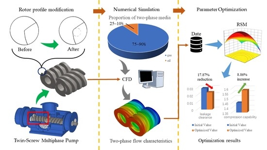
The objective of this study is to methodically examine the internal flow characteristics and performance enhancement pathways of twin-screw mixed-flow pumps under conditions of high gas content. The present focus of academic research on twin-screw pumps is predominantly on internal multiphase flow characteristics in pure liquid conditions or low gas content scenarios. A comprehensive and clear understanding of the variation patterns of key flow field parameters, such as pressure pulsations and velocity field distributions, under conditions of high gas content, remains elusive. Furthermore, extant studies have focused predominantly on the description and analysis of flow characteristics. However, there has been a neglect of the active control and optimization of mixed-flow pump performance under conditions of elevated gas content. This results in a significant disconnect between flow analysis and the design process for performance enhancement. In order to address the practical challenges posed by high-gas-content mixed-transport operations in the Changqing Oilfield, and to undertake a systematic investigation into the internal flow characteristics of twin-screw mixed-transport pumps under high-gas-content conditions with a view to performance optimization, this study will undertake the following tasks: Firstly, the overall design scheme and key structural parameters of the twin-screw mixed-transport pump will be determined based on the flow characteristics of high-gas-liquid two-phase mixed media. Secondly, numerical simulations of multiphase flow in the pump rotor region are conducted, employing CFD methods combined with a two-phase mixture model and the SST k-ω turbulence model. The primary objective of this study is to analyze the distribution and evolution patterns of pressure and velocity fields under high gas-liquid ratios and varying screw rotational speeds. In the subsequent stage of the research, we employed response surface methodology to perform a co-optimization of multiple performance metrics. These metrics included leakage volume and pressure-boosting capability. The screw depth, screw lead, and correct arc radius were identified as the key design variables. The present study establishes a comprehensive design workflow, spanning flow mechanisms to performance enhancement. This fills a research gap in the field between flow analysis and structural optimization.

2. Twin-Screw Pump Design Theory

2.1. Twin-Screw Pump Medium Conveying Principle

The twin-screw pump functions by generating suction and facilitating the discharge of the medium through the meshing motion of the double rotor. The working principle and process are illustrated in Figure 1. It has been established that, during operation, the motor drives the driving rotor in a rotary direction. Furthermore, it has been determined that power is transmitted to the driven rotor through the synchronous gear. This enables the two rotors to achieve synchronous reverse rotation. The construction consists of a series of continuous sealed chambers, formed between the spiral sleeve located on the rotor surface and the pump body bushing. It has been demonstrated that, due to the constant rotation of the rotor, these sealing chambers move smoothly from the suction side to the discharge side along the axial direction. This ensures the continuous and non-pulsating transportation of the high gas-bearing medium from the inlet to the outlet. Consequently, this results in stable and reliable oil-gas mixed transportation. The apparatus under consideration features a double-headed rotor design, which enables the rotor to complete the entire conveying process of two independent chambers with every rotation cycle. The specific stages in this process are outlined as follows:
(1)
Inhalation stage 1 (0-1/4T): The rotor is initiated into rotation from its initial position, thus inducing an increase in the volume of the suction side chamber. This results in the formation of a negative pressure, which in turn causes the medium to be drawn into the chamber. The chamber volume attains its maximum at 1/4T.
(2)
Discharge stage 1 (1/4-1/2T): The rotation of the rotor is sustained, resulting in a gradual augmentation of the volume of the discharge side chamber. Concurrently, the inhaled medium is propelled into the adjacent downstream chamber along the axial direction. Attaining a point of 1/2T, the volume of the discharge side chamber attains its maximum, and the overall volume of the chamber reverts to its initial state.
(3)
Inhalation stage 2 (1/2-3/4T): The rotor transitions into the second delivery cycle, with the chamber state maintaining consistency with that observed during the inhalation stage 1. Subsequently, the volume undergoes an increase from a minimal to a substantial state for the subsequent inhalation.
(4)
Discharge stage 2 (3/4-1T): The chamber state is analogous to that of discharge stage 1. The volume undergoes a decrease from a large to a small size, with the medium being propelled towards the outlet. Upon attaining a rotational speed of 1T, the rotor undergoes a return to its initial position, thus completing a one-cycle rotation. This results in the continuous transportation of two chambers.
The kinematic relationship between the driving and driven rotors is significant for determining the displacement per revolution of the screw pump and, therefore, the flow rate of the twin-screw pump. The formula for the theoretical flow q L is as follows [27]:
q L = 2 A L n ,
where L is the helical lead; n is the theoretical speed; and A is the cross-sectional area of the flow on the working length of the spiral:
A = A 3 2 A 1 ,
where A 1 is the cross-sectional area of a screw, and A 3 is the cross-sectional area of the inner hole of the screw bushing:
A 1 = 4 3 R r j sin Φ a b 2 r j 2 + R 2 Φ a b + 12 r j 2 1 sin Φ b c + 2 τ r r 2 + 2 τ R R 2 ,
A 3 = 2 π R 2 R 2 γ sin γ ,
where 2 τ r is the center angle of the tooth root circle, 2 τ R is the center angle of the addendum circle, R is the addendum circle radius, r j is the pitch circle radius, r is the root circle radius, Φ a b is the tooth profile rotation angle of ab, Φ b c is the tooth profile rotation angle of bc, and γ is the central angle of the rotor meshing line.
Under actual working conditions, the rotor assembly clearance will lead to medium leakage. The formula for calculating the total leakage of the gap q T H is as follows:
q T H = 16 n B A r R 2 r 2 ,
where A r is the area of the annular space between the outer diameter and the inner diameter of the screw, and B is the width of the screw.
Therefore, the formula for the actual flow q of the twin-screw pump is as follows:
q = q L q T H ,

2.2. Rotor Profile Modification

Under conditions of high-gas-content, the tip of the rotor tooth tends to develop cracks or deform due to stress concentration, which can reduce the efficiency of the mixed pump or even cause equipment failure. To address local stress concentration caused by the sudden change in curvature at the tip of the tooth’s original profile, this paper employs the arc transition method to modify the original shape, establishes the geometric model of the rotor, and characterizes it using the vector method (as shown in Figure 2). The model replaces the original cusp with a smooth arc, thereby improving the stress distribution. The specific construction process is as follows:
The pitch circle O on the helical end face of the screw is regarded as the moving circle, and the pitch circle O′ of the other screw is regarded as the fixed circle. In the event of the fixed circle rotating anticlockwise by an angle θ, the rolling circle will rotate clockwise by an angle θ′, and it can be demonstrated that the geometric parameters of the two rotors of the twin-screw pump are equal, i.e., θ = θ′, thus forming the vector ΔOPO′.
The epicycloid bc is generated by a generating point P on the pitch circle (assuming P is in the horizontal position). Then the coordinates of point P (in the rolling circle coordinate system) are as follows:
r P O = r j i
Coordinates of epicycloid bc (in the fixed circle coordinate system):
r b c O = K θ + θ r P O + d K θ i = r j K 2 θ + 2 K θ i
where d is the center-to-center distance between two circles, and K is the rotation matrix:
K = cos φ sin φ sin φ cos φ
where φ is the rotation angle.
The prolate epicycloid ab is generated by a generating point P′ on the addendum circle of the moving circle (assuming P′ is in the horizontal position). Then the coordinates of point P (in the rolling circle coordinate system) are as follows:
r P O = R i
Coordinates of prolate epicycloid ab (in the fixed circle coordinate system):
r a b O ¯ = K θ + θ + γ r P O + d K θ + γ i = R K 2 θ + γ + d R K θ + γ i
The modified circular arc cd is generated by a generating point P1 on the modified circle (assuming P1 is in the horizontal position). Then, the coordinates of point P1 (in the rolling circle coordinate system) are as follows:
r p 1 O = R r i
Coordinates of modified circular arc cd (in the fixed circle coordinate system):
r c d O = K θ θ + θ c d r p 1 O + r K θ i = R r K θ c d + r K θ i
where θcd is the central angle subtended by the modified arc cd.

2.3. Design Case

This paper presents the structural design of a twin-screw mixing pump with a high gas content, based on the design parameters of the MPC208-67 twin-screw pump used in the Changqing Oilfield. The design considers the pump’s actual working conditions and the field’s mixing and conveying requirements. The specific structure is shown in Figure 3. Its overall structure adopts a double-suction-single-discharge configuration. The main components include the pump body, driving rotor, driven rotor, transmission component (synchronous gearbox), sealing component (left and right bearing group and mechanical seal), pump port filter, and bottom support. The maximum outer diameter of the designed twin-screw oil-gas multiphase pump is 600 mm, the number of single-stage meshing cavities of the rotor is 4, the wall thickness of the bushing is 10 mm, the maximum diameter is 260 mm, the designed flow rate is 300 m3/h, and the inlet and outlet pressure difference is 1.6 MPa during operation. The rated speed is 1480 r/min, the gas content of the conveying medium is 70–80%, and the temperature is −20 °C to 60 °C. The total length of the screw rotor is 1300 mm, and the gap between the stator and rotor is 0.2 mm. The detailed structural parameters are listed in Table 1.
To evaluate the performance of the designed twin-screw multiphase pump under high-gas-content conditions, this paper employs the CFD method to simulate and analyze the internal flow characteristics at different gas contents and rotational speeds, based on the Mixture model and the SST k-ω model. The working performance is quantitatively evaluated by comparing the simulation results with the design indexes, thereby providing a direct basis for optimizing the parameters of subsequent key structures.

3. Numerical Simulation Method

3.1. Two-Phase Flow Model

In this paper, the focus is on the internal two-phase flow in the mixed pump. At present, the commonly used multiphase flow models include the VOF model, the Eulerian model, and the Mixture model [28]. Among the three multiphase flow models, the Mixture model is most suitable for studying the internal flow characteristics of the twin-screw multiphase pump rotor. The model is widely used to simulate multiphase flow in rotating machinery due to its ability to handle multiphase flow under strong shear forces [29,30]. The basic governing equations are as follows:
Continuity equation
The mixture’s continuity equation is:
t ρ m + · ρ m v m = 0 ,
Among them,
v m is the average mass velocity:
v m = k = 1 n α k ρ k v k ρ m ,
ρ m is the density of the mixture:
ρ m = k = 1 n α k ρ k ,
where α k , ρ k , and v k are the volume fraction, density, and velocity of phase k, respectively.
The momentum equation
The mixture’s momentum equation can be obtained by summing the individual momentum equations of all phases. It can be expressed as:
t ρ m v m + · ρ m v m v m          = p + · μ m v m + v m T + F · k = 1 n α k ρ k v d r , k v d r , k ,
where n is the number of phases, p   is the mixture pressure, F is the body force, v d r ; k is the drift velocity of the secondary phase k, and μ m is the viscosity of the mixture:
μ m = k = 1 n α k μ k ,
where μ k is the viscosity of phase k.
Energy equation
The energy equation of the mixture is:
t k α k ρ k E k + k α k ν k ρ k E k + p         = k e f f T k j h j , k J j , k + τ e f f ν ,
where h j , k is the enthalpy of substance j in phase k, J j , k is the diffusion flux of substance j in phase k, T is the mixture temperature, k e f f is the effective thermal conductivity, and τ e f f is the effective stress tensor.
k e f f = α k k k + k t ,
where k k is the molecular thermal conductivity of phase k and k t is the turbulent thermal conductivity.
E K is the total energy of phase k:
E K = h k p ρ k + v 2 2 ,
where h k is the apparent enthalpy of phase k. For the compressible phase, E K = h k .

3.2. Turbulence Model

Currently, the most commonly used turbulence models include the Standard k-ε, Realizable k-ε, RNG k-ε, and SST k-ω models. Table 2 presents a comparison of these models.
Among the four turbulence models mentioned above, the SST k-ω model [31] offers distinct advantages for simulating internal flows in rotating machinery. It combines the strengths of the k-ε and k-ω models and incorporates a shear-stress limiter, which improves the prediction of typical rotating-flow features such as strong shear, flow separation, and complex vortex structures. Its applicability has been widely validated in related studies. Wu et al. [32] employed this model to investigate the evolution of tip-leakage vortices in axial-flow pumps and verified the numerical results through experiments. Ahmed et al. [33] applied the SST k-ω model to analyze unsteady flow and pressure pulsations in pumps, with the simulations showing good agreement with experimental data. Zhao et al. [34] used a modified SST k-ω model to simulate cavitation and pump performance in centrifugal pumps, and their results were also supported by experiments.
As a typical type of rotating machinery, twin-screw pumps are prone to disturbed flow patterns when the fluid passes through designed clearances, which can strongly affect the internal flow field within the pump chamber [26]. The SST k-ω model can provide reliable descriptions and predictions of such complex flow behavior. Therefore, this study adopts the SST k-ω model for numerical simulations of the rotor region in twin-screw multiphase pumps to enhance the accuracy and credibility of the internal flow-field analysis.
The governing equations are as follows:
The transport equation of turbulent kinetic energy k is:
ρ k t + ρ k u i x i = x j μ + σ k μ t k x j + P k β * ρ k ω ,
where μ is the molecular dynamic viscosity, σ k is the Prandtl number of turbulent kinetic energy, μ t is the turbulent viscosity and P k is the turbulent kinetic energy production term.
The turbulent viscosity μ t is introduced into the limiter, defined as follows:
μ t = ρ k ω 1 m a x 1 α * , S F 2 a 1 ω ,
where S is the strain rate, α * is the low Reynolds number correction coefficient, a 1 is a model constant of the SST k-ω turbulence model and blending function F 2 is defined as follows:
F 2 = t a n h ( m a x 2 k β * ω y , 500 μ ρ y 2 ω 2 ) ,
where y is the distance to the next surface.
The transport equation of specific dissipation rate ω is:
ρ ω t + ρ ω u i x i = x j μ + σ k μ t ω x j + α ω k P k ρ β ω 2 + 2 1 F 1 ρ σ ω 2 1 ω k x j ω x j
where β * , α , and β are model constants and Blending function F 2 is defined as follows:
F 1 = tanh m i n m a x k β * ω y , 500 μ ρ y 2 ω , 4 ρ σ ω 2 k C D k ω y 2 4 ,
where C D k ω is the cross-diffusion term.

3.3. Modeling and Meshing

Due to the symmetrical design of the driving and driven rotors in the double-head twin-screw mixed pump, only one end of the rotor needs to be calculated and simulated. In the three-dimensional model, a rotor rotation domain with a length of 240 mm, a maximum outer diameter of 241 mm, and a 0.2 mm gap is defined between the driving and driven rotors, and likewise between the bushing and each rotor., and the internal flow field is assumed to be as follows: (1) neglect the influence of temperature change in the conveying medium on the flow field characteristics of the multiphase pump; (2) there is no other leakage or circulation interface except for the set inlet and outlet of the flow channel, and the internal medium is only the oil-gas two-phase mixture; and (3) the inner and outer walls of the screw rotor and the bushing are regarded as rigid boundaries, and no deformation occurs during the working process.
To ensure calculation accuracy, the established model is divided into hexahedral structural grids. The number of circumferential grid layers is set to 25, the number of radial grid layers to 45, the minimum cell size to 5 mm, and the number of iterations to 8000. At the same time, mesh refinement is performed on the rotor meshing area and the boundary area. The established fluid domain grid for the twin-screw pump rotor is shown in Figure 4. In the figure, blue grids denote the driving rotor and its fluid domain, while red grids denote the driven rotor and its fluid domain.
The number of grids affects the accuracy and calculation time of numerical simulation. Therefore, the simulation is carried out under the condition of 80% gas content. The working pressure is selected as the verification parameter, and three different meshing schemes are developed, as shown in Table 3, for grid independence verification. The verification results are shown in Figure 5. The horizontal axis of the diagram is the distance from the center point of the circumferential section along the Z-axis from the inlet to the outlet, and the vertical axis is the pressure value at the point.
The y+ value is a dimensionless parameter commonly used in CFD to characterize the nondimensional wall distance of the first near-wall cell. Specifically, it represents the dimensionless distance from the center of the first grid layer adjacent to the wall to the wall surface. Using an appropriate near-wall grid resolution (i.e., a suitable y+ range) often improves the accuracy of numerical simulations. The y+ value is defined as follows:
y + = y ρ μ τ μ
where y is the wall-normal distance; μ τ is the wall shear velocity.
Considering the influence of y+ on the accuracy of the SST k-ω turbulence model, boundary-layer refinement was applied to the outer surfaces of both the driving and driven rotors in the computational domain. The boundary layer consisted of 11 layers with a growth rate of 1.12. For fluid-machinery simulations, it is generally recommended that the y+ value of the first near-wall cell be less than 5 [35]. As shown in Figure 5, the y+ values of most wall nodes are distributed between 1 and 5, indicating that the mesh resolution near the wall is sufficient and satisfies the calculation requirements.
As shown in Figure 5, when the number of grids reaches 1,356,736, the simulation results show no significant change. To ensure the accuracy of the results and to meet the practical need to reduce computational cost, the subsequent calculation uses a grid with 1,356,736 cells.

3.4. Boundary Conditions and Calculation Methods

The CFD approach was employed to conduct a numerical simulation of gas-liquid two-phase flow within the rotor rotating region of a twin-screw multiphase pump. The solver employed was pressure-based, and steady-state calculations were performed. The initial and boundary conditions were specified according to the on-site operating conditions. The Mixture multiphase model was employed, with crude oil defined as the liquid phase and oilfield-associated gas defined as the gas phase. The turbulence model employed in this study was formulated using the SST k-ω model, with the default y+ insensitive enhanced wall treatment. The primary simulation parameters are enumerated in Table 4.
In the model, the flow field analysis and calculation use five boundary conditions: the inlet end face, the outlet end face, the outer surface of the active screw, the outer surface of the driven screw, and the inner surface of the bushing. The inner surface of the bushing is set as a no-slip boundary, and the rotor surface is set as a rotating surface. The driving screw rotor rotates clockwise, and the driven screw rotor rotates counterclockwise. The inlet and outlet boundary conditions are a pressure inlet and a pressure outlet, respectively. The SIMPLEC algorithm is used in the solution process, and the convergence accuracy is set to 1.0 × 10⁻⁴. The time step is set to 0.001 s, and the maximum number of iterations per time step is 30. The time step is dynamically adjusted based on the flow characteristics of the fluid under different working conditions, and the remaining relevant parameters are shown in Table 5.

3.5. Model Validation

To validate the numerical model, the simulated flow rate and volumetric efficiency of the screw pump were compared with the experimental results reported by Sun et al. [36]. To ensure the reliability of the validation, the simulated operating conditions were set to be consistent with those in the literature, as listed in Table 6. The comparison between the numerical predictions and the experimental measurements is presented in Figure 6. As shown, the simulation results agree well with the experimental data, and the overall mean deviation remains within the acceptable error margin (5%). Therefore, the established model is considered reliable and suitable for subsequent numerical analyses.

4. Results and Discussion

4.1. Effect of Air Rate on Flow Field Characteristics Within a Multiphase Pump

The pressure distribution in the rotor engagement gap region of the twin-screw pump under different gas content conditions is shown in Figure 7. The results demonstrate that the pressure under a single working condition shows a significant stepwise increase from the inlet to the outlet. From the standpoint of gas content, there is a substantial decline in the overall pressure level within the flow field when the gas content undergoes an increase from 75% to 90%. In the outlet section, given the markedly higher compressibility of the gas phase compared to the liquid phase, an augmented gas content enhances the overall compressibility of the medium. Consequently, this leads to a diminished pressure rise at a constant compression ratio. Concurrently, as the gas content rises, the pressure differential between the inlet and outlet diminishes. At a gas content of 75%, the pressure differential can reach approximately 1.64 MPa, while at 90% gas content, the pressure differential experiences a substantial decrease to approximately 1.48 MPa. This indicates that the pump’s boosting capacity experiences a decline in proportion to the rise in gas content.
To further analyze the axial pressure distribution in the rotor meshing zone of the twin-screw pump, Figure 8 shows the pressure distribution cloud diagram of the axial section of the rotor meshing zone under four working conditions. A local high-pressure zone forms in the corner region of the meshing clearance, with a peak pressure of about 2.08 MPa at 75% gas content. However, as the void fraction increases from 75% to 90%, the pressure level in the high-pressure zone decreases significantly, the peak pressure drops below about 1.95 MPa, and the internal pressure gradient is markedly reduced, with the distribution tending toward uniformity. At the same time, the pressure in each chamber of the positive rotor tends to stabilize as the gas content increases, with no significant pressure mutation area, and the pressure area gradually decreases with increasing gas content. The pressure distribution law of the negative rotor is basically similar to that of the positive rotor. Since the core working principle of the two is the same (the sealing cavity is formed by meshing), the specific mechanism of pressure distribution is not described here.
To explore the influence of void fraction on the pressure distribution in the meshing zone of the twin-screw pump rotor, Figure 9 shows the pressure distribution cloud diagram of the XOY parallel section at Z = 120 mm under different void fraction conditions. The analysis results show that the pressure in the rotor’s meshing zone is significantly higher than in the non-meshing zone, and that the distribution exhibits the characteristic that the pressure at the lower end is higher than at the upper end. As the void fraction increases, the pressure field distribution in this section gradually stabilizes, and the pressure gradient decreases accordingly.
To illustrate the influence of gas content on the velocity distribution in a twin-screw pump, Figure 10 shows velocity vectors indicating the flow direction (the inlet end face is on the right and the outlet end face on the left). Under all operating conditions, the overall velocity level in the rotor domain remains broadly similar, with most velocities distributed in the range of 0–22 m/s. Notably, the rotor meshing region and the clearance between the rotor tips and the pump casing consistently exhibit the largest velocity gradients, making them the primary locations of high-velocity zones.
At a gas content of 75%, peak velocities in these critical regions reach 30–40 m/s, with localized areas approaching 50 m/s. As the gas content increases from 75% to 90%, velocities in these regions rise further. The area occupied by the 30–40 m/s high-velocity zone expands significantly, especially near the meshing line where velocities consistently exceed 50 m/s. Meanwhile, the proportion of red-colored high-velocity regions in the rotor meshing clearance increases markedly, indicating a sustained increase in velocity within this zone.
To visually demonstrate the flow characteristics on the XOY plane at Z = 120 mm under different gas content ratios, Figure 11 shows the velocity-vector distributions for gas contents of 75%, 80%, 85%, and 90%. The velocity patterns are generally consistent across all four conditions. High velocities occur in the region between the rotor outer circumference and the inner wall of the bushing, typically ranging from 26 to 47 m/s, with local peaks approaching 60 m/s. In contrast, velocities in other regions remain relatively stable and are mainly distributed within 0–22 m/s. The rotor meshing region exhibits strong velocity gradients, where abrupt changes in vector direction and local backflow can be observed in the clearance zone.
As the gas content increases from 75% to 90%, the section-averaged velocity remains largely unchanged, and the mainstream velocity still lies within 0–22 m/s. Nevertheless, the high-velocity zone in the rotor meshing region expands continuously and its velocity level increases steadily. Meanwhile, discrete vortex structures appear in the spiral groove; their intensity strengthens with increasing gas content, and their affected area expands accordingly. These observations indicate that elevated gas content has a pronounced impact on local flow structures. At 90% gas content, the velocity in the high-speed zone of the meshing region increases to a range of 53.41–58.25 m/s.

4.2. Effect of Rotational Speed on Flow Field Characteristics Within a Multiphase Pump

Under working conditions of inlet pressure of 0.2 MPa, outlet pressure of 1.8 MPa, and gas content of 80%, four sets of rotational speeds (1280 r/min, 1480 r/min, 1680 r/min, and 1880 r/min) were set, and the time step was adjusted accordingly to maintain coordination with the rotational speed. Along the axial direction of the screw (Z direction), from the starting point to the end point, a total of 10 monitoring points were set up, with positions aligned with the center of each chamber, to measure speed and pressure at each point at different speeds. The results are shown in Figure 12. The monitoring data show that, under different rotational speeds, the speed at each monitoring point exhibits periodic characteristics. As the speed gradually increases from 1280 r/min to 1880 r/min, the speed at each monitoring point increases overall, rising from about 20 m/s at 1280 r/min to about 36 m/s at 1880 r/min. At the same time, the amplitude of velocity fluctuations decreases with increasing rotational speed, and the flow tends to stabilize. With increasing axial distance from the monitoring point, the overall pressure shows an upward trend. The peak pressure is about 1.93 MPa at 1280 r/min and about 1.68 MPa at 1880 r/min. At the same axial position, the higher the rotational speed, the lower the corresponding working pressure value.
Preliminary field tests conducted in the Changqing Oilfield have indicated that, under typical high-gas-content conditions, the pressure differential between the inlet and outlet of the multiphase pump is slightly lower than the rated value. Further analysis indicates that, within the established design parameters, the pump demonstrates the capacity to sustain consistent performance at the stipulated design objectives—an outlet pressure of 1.6 MPa and a flow rate of 300 m3/h—when operating at 1480 r/min and a gas content ranging from 70% to 80%. These conditions are sufficient to satisfy the requirements for gathering and transporting high-gas oil–gas mixtures. Furthermore, an analysis of the pressure contours and velocity streamlines indicates that an increase in gas content has a substantial impact on both operational reliability and transport efficiency in the multiphase pump.

5. Optimization of Parameters Based on Response Surface Methodology

To improve the overall performance of the designed multiphase pump, this paper uses the response surface method to optimize multi-objective parameters based on the design example parameters. Due to internal leakage in the twin-screw pump, the actual flow rate is lower than the theoretical flow rate; at the same time, the pressurization performance of the twin-screw mixed pump significantly affects the operational efficiency, stability, and reliability of the entire transportation system. Therefore, this paper sets the leakage gap and pressurization capacity of the twin-screw pump as the optimization targets, as shown in Table 7. Key design parameters, such as helix depth, helical lead, and correct arc radius, are selected as the optimization design variables, and their corresponding parameter ranges are determined. The details are shown in Table 8.
By varying the helix depth, helical lead, and correct arc radius, the leakage gap and the pressure difference between the inlet and outlet are calculated under different design parameters. Through the analysis of orthogonal test results:
(1)
For the leakage gap δ , the objective function is defined as follows:
δ = 0.0293 + 0.0028 h 0.0051 L 0.0025 r + 0.0008 h L 0.0005 h r 0.0007 L r + 0.0009 h 2 0.0045 L 2 + 0.0006 r 2 ,
where h is the helix depth.
Among these, the helix depth h, the helical lead L, and the correct arc radius have a significant impact on the leakage gap (p values are less than 0.0001). The fitting equation aligns with the test principle and shows good adaptability. The synergistic effect is shown in Figure 13. The colour gradient in the figure reflects the numerical change in the maximum leakage gap δ, and the points in each subfigure correspond to the extreme value points for different combinations of variables. The figure shows that when the arc radius r′ is held constant, the maximum leakage gap δ increases with helical depth h and decreases with helical lead L. When L is held constant, δ increases with h and decreases with r′. When h is held constant, δ decreases with L and increases with r′.
(2)
For the inlet and outlet pressure difference P , the objective function is defined as follows:
P = 1.58 + 0.0337 h 0.0613 L 0.03 r + 0.0125 h L 0.025 h r 0.005 L r + 0.0063 h 2 0.0263 L 2 + 0.0113 r 2 ,
Among them, the helical lead L and the correct arc radius have a very significant effect on the inlet-to-outlet pressure difference (p value is less than 0.0001). The helix depth h and the correct arc radius r also significantly affect the inlet-to-outlet pressure difference. The fitting equation conforms to the test principle and shows good adaptability. The synergistic effect is shown in Figure 14. The colour gradient in the figure shows the numerical variation of the maximum inlet-outlet pressure difference P, and the points in each subfigure correspond to extreme points under different combinations of variables. The figure shows that when the arc radius r′ is kept constant, P increases with helix depth h and decreases with helical lead L. When L is kept constant, P increases with h and decreases with r′. When h is kept constant, P decreases with L and increases with r′.
The formula above is used to construct a multi-objective function and is defined as follows:
m i n y = F x = δ , P ,
s . t . h = 0.45 ~ 0.7 L = 60 ~ 150 x = h , T , r , δ , P ,
The design variables and constraints in Table 7 are incorporated into the multi-objective function, and the multi-objective optimization model is then constructed and solved. The optimization results are presented in Table 9.
After optimization, the leakage gap is reduced from 0.0293 mm to 0.0238 mm, a 17.87% reduction. The inlet-to-outlet pressure difference increased from 1.45 MPa to 1.58 MPa, an 8.86% increase. The working performance is significantly improved, providing a reference for its practical design, development, and application.

6. Conclusions

This study conducted structural design and rotor profile optimization of the mixed transportation pump, considering the diverse transportation demands of high gas-bearing oil and gas resources in the Changqing Oilfield. The numerical simulation method was employed to examine the multiphase flow characteristics within the mixed transportation pump under high gas-bearing conditions, and a multi-objective optimization of critical structural parameters was conducted. The principal conclusions are as follows:
(1)
The arc transition method is employed to rectify the rotor profile, while the design scheme and essential structural parameters of the MPC208-67 twin-screw multiphase pump are established based on the requirements for high gas-bearing oil and gas mixed transportation in the Changqing Oilfield. The profile removes the tooth tip and mitigates local stress concentration on the rotor, thereby diminishing the likelihood of rotor deformation and significantly enhancing the operational stability and environmental adaptability of the pump under complicated settings with high gas content.
(2)
The flow field inside a pump is simulated numerically using a mixture multiphase flow model and an SST k-ω turbulence model. The simulation findings indicate that when the void fraction of the conveying medium increases, the pressure differential between the inlet and exit of the rotor fluid domain exhibits a declining trend, and a high-velocity flow region is readily established in the gap between the driving and driven rotors. Simultaneously, while an increase in screw speed enhances the total flow rate of the fluid domain, it results in a concomitant reduction in pressure. Under the specified operational conditions, the multiphase pump achieved an outlet pressure of 1.8 MPa and a flow rate of 300 m3/h, with all metrics meeting design specifications. This demonstrated the pump’s capacity to sustain stable pressurization performance in the intricate and variable high gas-bearing environment, thereby effectively validating the feasibility and reliability of the design scheme in high gas-bearing conditions, such as those present in the Changqing Oilfield.
(3)
The multi-objective optimization of the engineered multiphase pump is conducted utilizing the response surface methodology. The helix depth, helical lead, and correct arc radius are designated as the optimization variables. The leakage gap of the multiphase pump has been diminished by 17.87%, while the pressure differential between the intake and output has been augmented by 8.86%. The structural optimization parameters derived offer a scientific basis for the selection of twin-screw pumps in subsequent high-gas-content scenarios, facilitate a reduction in the design cycle of analogous products, enhance the rationality of the design, and support the performance optimization of related equipment.
The research results are highly relevant for engineering practice and subsequent in-depth research into twin-screw mixing pumps. The proposed rotor profile optimisation model and method can provide innovative structural design ideas for similar multiphase pumps, alleviating the problem of stress concentration at the top of the teeth. The simulation and analysis results under high-gas-containing conditions provide a direct and reliable basis for optimising the performance of such pumps. The optimisation method for the structural parameters and related results also lay a solid foundation for further improving the comprehensive performance of mixing pumps.
This study has several limitations: first, the conclusions are constrained by the predefined working conditions, necessitating further validation across diverse conditions; second, the pump body’s performance under extreme gas conditions of 90–95% remains unexamined; and third, the engineering applicability of the simulation results requires additional verification through experimental data, as support from the physical prototype is lacking.

Author Contributions

Conceptualization: W.X. and L.C.; Methodology: W.X. and L.C.; Software: L.C.; Validation: W.X.; Formal Analysis: W.T.; Investigation: X.W.; Resources: W.T., X.W., S.X. and Y.L.; Data Curation: Y.L., S.X. and W.X.; Writing-Original Draft Preparation: L.C.; Writing-Review and Editing: W.X.; Visualization: W.T. and L.C.; Supervision: W.T.; Project Administration: S.X.; Funding Acquisition: Y.L. All authors have read and agreed to the published version of the manuscript.

Funding

This research was funded by the Open Project of National Engineering Laboratory for Exploration and Development of Low-Permeability Oil and Gas Fields: Integrated Technology Process of “Wellbore Insulation-Hydrate Prevention-Wellhead Throttling” (Grant Number KFKT2024-13, CQYT-CQYQY-2024-JS-1506), and Oil and Gas National Science and Technology Major Project “Intelligent Sensing Wellbore and Efficient Artificial Lifting/Drainage Equipment for Oil and Gas Wells-Key Technologies and Equipment for Efficient Intelligent Oil and Gas Production Engineering” (Grant Number 2024ZD1406503).

Data Availability Statement

The datasets generated and analyzed during the current study are available from the corresponding author on reasonable request.

Conflicts of Interest

Authors Wei Tian, Xiongxiong Wang, Shuqin Xiao, and Yanbin Li were employed by the PetroChina Changqing Oilfield Company. The remaining authors declare that the research was conducted in the absence of any commercial or financial relationships that could be construed as a potential conflict of interest.

Nomenclature

List of Symbols
A The cross-sectional area of the flow on the working length of the spiral mm2
A 1 Cross-sectional area of the screw mm2
A 3 Cross-sectional area of the inner hole of the screw bushing mm2
A r Area of annular space blocked by thread mm2
a 1 , α, α*, β, β* Coefficients of the SST k-ω turbulence model
B Width of thread mm
C D k ω Cross-diffusion
d Screw shaft center spacing mm
E K The total energy per unit mass of k-phase J/kg
F External volume force N
F 1 ,   F 2 Blending function of the SST k-ω turbulence model
g Gravitational acceleration m/s2
h Helix depth %
h j k The enthalpy of substance j in phase k J/kg
h k The specific enthalpy of k-phase J/kg
J j k Diffusion flux of substance j in phase k kg/(m2·s)
K Rotation matrix
k Turbulent kinetic energy m2/s2
k e f f Effective thermal conductivity W/(m·K)
k k The molecular thermal conductivity of the k-phase W/(m·K)
k t Turbulent thermal conductivity W/(m·K)
L Lead of screw mm
n Theoretical rotative speed r/min
P Inlet-outlet pressure difference MPa
p Mixture pressure Pa
q Actual flow rate m3/h
q L Theoretical flow rate m3/h
q T H Total clearance leakage m3/h
r p The position vector of P mm
r a b Position Vector of Prolate epicycloid ab mm
r p The   position   vector   of   p mm
r b c Position Vector of Epicycloid bc mm
r p 1 The   position   vector   of   p 1 mm
r c d Position Vector of correct circular Arc cd mm
R Radius of addendum circle mm
r j Radius of pitch circle mm
r Radius of root circle mm
r Radius of correct arc mm
S Shear-strain rate 1/s
T Mixture temperature K
v Velocity vector m/s
y The distance to the nearest wall mm
Greek Symbols
α k The volume fraction of the k-phase
γ Half central angle of screw helical meshing line rad
δ Leakage clearance mm
Φ Tooth shape rotation angle rad
μ Dynamic viscosity Pa·s
μ τ Wall Shear Velocity m/s
ρ Density kg/m3
σ Turbulent Prandtl number
τ e f f Effective stress tensor Pa
τ Center angle rad
ω Specific dissipation rate 1/s
Subscript/superscript
Subscript ab Prolate Epicycloid ab
Subscript bc Epicycloid bc
Subscript   d r ,   k Drift velocity of the k-phase
Subscript k The k-th phase
Subscript m Mixture phase
Subscript t Turbulent
Subscript   θ Rolling circle rotation angle rad
Subscript   θ Fixed circular rotation angle rad
Subscript   θ c d Modified circle rotation angle rad
Superscript O Rolling Circle Coordinate System
Superscript O Fixed Circle Coordinate System

References

  1. Zhang, J.; Shu, J.; Yong, J.; Hong, W.; Yong, Z. Visualization study of gas-liquid two-phase flow patterns inside a three-stage rotodynamic multiphase pump. Exp. Therm. Fluid Sci. 2016, 70, 125–138. [Google Scholar] [CrossRef]
  2. Zhang, J.; Cai, J.; Zhu, H.; Zhang, Y. Experimental investigation of the flow at the entrance of a rotodynamic multiphase pump by visualization. J. Pet. Sci. Eng. 2015, 126, 254–261. [Google Scholar] [CrossRef]
  3. Fall, I.; Geng, L.; Gao, Y.; Appiah, D.; Ali, A.; Zhang, D. Investigation of pressure pulsation and unsteady multiphase flow characteristics in multiphase rotodynamic pump using dynamic mode decomposition. Phys. Fluids 2025, 37, 085162. [Google Scholar] [CrossRef]
  4. Qiu, Z.; Du, D.; El-Emam, M.; Agarwal, R.; Zhou, L. Numerical and experimental study of dynamic gas-liquid separator with various viscosities. Int. J. Fluid Eng. 2024, 1, 043904. [Google Scholar] [CrossRef]
  5. Parikh, T.; Mansour, M.; Thévenin, D. Investigations on the effect of tip clearance gap and inducer on the transport of air-water two-phase flow by centrifugal pumps. Chem. Eng. Sci. 2020, 218, 115554. [Google Scholar] [CrossRef]
  6. Alsarkhi, A.; Ben-Mansour, R.; Ejim, C.; Badr, H.; Banjar, H. Experimental investigation of a novel gas-liquid homogenizer methodology for ESP in high GVF flow applications. Results Eng. 2024, 24, 103040. [Google Scholar] [CrossRef]
  7. Han, W.; Nan, H.; Ju, P.; Zhang, H.; Li, F.; Li, R. Effect of the maximum thickness of a composite airfoil on the performance of a helical axial-flow gas-liquid multiphase pump. Front. Energy Res. 2022, 10, 993974. [Google Scholar] [CrossRef]
  8. Wu, H.; Shen, X.; Ni, C.; Yang, G. Experimental and Numerical Investigation of Cavitation-Induced Pressure Fluctuation Characteristics in the Blade-Tip Region of an Axial Flow Pump. J. Mar. Sci. Eng. 2025, 13, 1391. [Google Scholar] [CrossRef]
  9. Mao, Y.; Liu, H.; Zanetti, G.; Cavazzini, G.; Wang, Y.; Chen, J. Experimental investigation on gas-liquid two-phase flow patterns and vibration characteristics of an inducer pump. Int. J. Heat Mass Transf. 2025, 238, 126518. [Google Scholar] [CrossRef]
  10. Long, Y.; Chen, X.; Zhou, L.; Fu, J.; Li, H. Analysis and Research on the Influence of Parameters and Operating Conditions on Fuel Gear Pump. Manuf. Autom. 2024, 46, 164–174. [Google Scholar] [CrossRef]
  11. Chen, Y.; Tian, C.; Ren, X.; Yan, M.; Li, C. Analysis of Full-basin Flow Field Characteristics of Turbine Self-pressurizing Axial Piston Pump. Chin. Hydraul. Pneum. 2024, 48, 29–36. [Google Scholar] [CrossRef]
  12. Kumar, P.; Krishna, M. Numerical investigation of thermo-hydraulic transport characteristics of two-dimensional, steady flow through partially porous wavy channel. Numer. Heat Transf. Part A Appl. 2021, 81, 31–47. [Google Scholar] [CrossRef]
  13. Shi, Z.; Zhao, T.; Cui, H.; Cao, B.; Hao, B.; Xu, H.; Zhang, X. Numerical simulation on heat dissipation characteristics of complex flow channel in high-power permanent magnet synchronous motors for mining. Coal Eng. 2025, 57, 152–159. [Google Scholar]
  14. Zhang, D.; Cheng, L.; Li, Y.; Jiao, W. The hydraulic performance of twin-screw pump. J. Hydrodyn. 2020, 32, 605–615. [Google Scholar] [CrossRef]
  15. Shen, J.; Yang, W.; Pan, W.; Cheng, L. Research on flow-induced radiated noise of twin-screw pumps based on the Lighthill acoustic analogue theory. J. Phys. Conf. Ser. 2024, 2854, 12–23. [Google Scholar] [CrossRef]
  16. Yan, D.; Kovacevic, A.; Tang, Q.; Rane, S. Numerical investigation of flow characteristics in twin-screw pump under cavitating conditions. IOP Conf. Ser. Mater. Sci. Eng. 2017, 232, 12–26. [Google Scholar] [CrossRef]
  17. Qiu, R.; Zhang, W.; Jiang, Q.; Shen, K.; Gread, B.; Yuan, S. Research on Full Flow Passage Characteristics of Double Screw Pump Based on Immersion Entity Method. J. Phys. Conf. Ser. 2022, 2186, 12–15. [Google Scholar] [CrossRef]
  18. Ye, Z.; Zeng, Z.; Lei, C.; Zhao, Y.; Pang, Y. Analysis of operating performance parameters of the internal twin screw pump. Iran. J. Sci. Technol. Trans. Mech. Eng. 2024, 48, 957–970. [Google Scholar] [CrossRef]
  19. Höckenkamp, S.; Grieb, M.; Utri, M.; Brümmer, A. Performance analysis of a water-injected twin-screw compressor in a high-temperature R718 heat pump. IOP Conf. Ser. Mater. Sci. Eng. 2024, 1322, 12–18. [Google Scholar] [CrossRef]
  20. Moghaddam, A.; Kutschelis, B.; Holz, F.; Skoda, R. Experimental investigations and 3D simulations by the overset grid method on twin-screw machines in both pump and turbine mode. IOP Conf. Ser. Mater. Sci. Eng. 2022, 1267, 12–22. [Google Scholar] [CrossRef]
  21. Moghaddam, A.; Kutschelis, B.; Holz, F.; Skoda, R. Experiments and three-dimensional flow simulations on twin-screw pumps operated as control valves for energy recovery. Energy 2024, 306, 132400. [Google Scholar] [CrossRef]
  22. Zhang, X.; Wang, L.; Zhu, G.; Han, W. Study on the Unsteady Cavitation Flow Characteristics Inside the Mixed Transport Twin Screw Pump. Int. J. Fluid Mach. Syst. 2024, 17, 80–87. [Google Scholar] [CrossRef]
  23. Wang, Z.; Sun, S.; Wu, P. Particle distribution and two-phase flow characteristics of twin-screw pump during solid-liquid transfer. J. Phys. Conf. Ser. 2024, 2707, 12–49. [Google Scholar] [CrossRef]
  24. Wang, Z.; Sun, S.; Guo, P.; Ma, J. Solid-liquid flow characteristics of twin-screw pump under solid-containing transportation. J. Phys. Conf. Ser. 2024, 2854, 12–46. [Google Scholar] [CrossRef]
  25. Zhao, Y.; Zhu, B.; Hou, H.; Zhao, S. Performance analysis of embedded tri-screw pump based on computational fluid dynamics. J. Mech. Sci. Technol. 2021, 35, 601–614. [Google Scholar] [CrossRef]
  26. Zhang, X.; Zhu, G.; Yao, Y.; Han, W.; Huang, X. Multiphysics Analysis of Gas-liquid Interaction in Triple-Screw Pumps: Impacts of Gas Volume Fraction on Transient Flow Dynamics and Rotor Mechanical Response. ACS Omega 2025, 10, 29285–29294. [Google Scholar] [CrossRef]
  27. Li, F.B. Screw Pump, 1st ed.; China Machine Press: Beijing, China, 2010; pp. 149–160. [Google Scholar]
  28. Hammawa, H.; Hamad, E. A simple and accurate mixture model. Fluid Phase Equilibria 1996, 122, 67–74. [Google Scholar] [CrossRef]
  29. Xu, K.; Xiang, P.; Zhou, Z.; Xiong, Y.; Yu, Z.; Liu, X.; Pang, J. Solid–Liquid Flow Analysis of Francis-99 Turbine Runner: Effects of Sediment Concentration. Energy Sci. Eng. 2025, 13, 4131–4142. [Google Scholar] [CrossRef]
  30. Dong, H.; Wan, R.; Huang, C.; Liu, S.; Luo, S.; Chen, L.; Li, S.; Song, X. Numerical Study of Internal Flow Field in a Disc Stack Centrifuge Based on Mixture-PBM Model. Appl. Sci. 2024, 14, 8070. [Google Scholar] [CrossRef]
  31. Menter, F. Two-equation eddy-viscosity turbulence models for engineering applications. AIAA J. 1994, 32, 1598–1605. [Google Scholar] [CrossRef]
  32. Zhao, W.; Zhao, G.; Xian, L.; Han, X. Effect of Surface-fitted Obstacle in Centrifugal Pump on Cavitation Suppression. Trans. Chin. Soc. Agric. Mach. 2017, 48, 111–120. [Google Scholar] [CrossRef]
  33. Wu, H.; Zhang, D.; Shen, X.; Ni, C.; Yang, G. Study on the Suppression of Tip Leakage Vortex in Axial Flow Pumps Based on Circumferential Grooving in the Rotor Chamber. J. Mar. Sci. Eng. 2025, 13, 972. [Google Scholar] [CrossRef]
  34. Ahmed, R.; Anas, A. Investigation of hydraulic transient flow and dynamic response performance of axial pump based on novel vibration signals characteristics and numerical analyses. Alex. Eng. J. 2025, 125, 104–126. [Google Scholar] [CrossRef]
  35. Li, Y.; Wang, Z.; Fan, Z. Numerical Evaluation of Unsteady Flow in a Centrifugal Pump by Omega Vortex Identification Method. J. Eng. Thermophys. 2021, 42, 3187–3194. [Google Scholar]
  36. Sun, S.; Wu, P.; Guo, P.; Yi, G.; Kovacevic, A. Numerical investigation on a twin-screw multiphase pump under low IGVF. Int. J. Fluid Mach. Syst. 2021, 14, 335–344. [Google Scholar] [CrossRef]
Figure 1. Working principle and process of the twin-screw pump. (a) Working principle. (b) Working process.
Modelling 07 00034 g001
Figure 2. Geometric vectorization representation of rotor correction profile.
Modelling 07 00034 g002
Figure 3. Structural diagram of a high-gas-content twin-screw oil and gas mixed-flow pump.
Modelling 07 00034 g003
Figure 4. Fluid domain of screw rotor.
Modelling 07 00034 g004
Figure 5. Grid quality inspection: (a) grid independence verification; (b) y+ distribution of the first boundary layer.
Modelling 07 00034 g005
Figure 6. Verification results under different cases: (a) flow rate; (b) volumetric efficiency.
Modelling 07 00034 g006
Figure 7. Pressure cloud map of the rotor meshing clearance section under different void fraction conditions: (a) 75%; (b) 80%; (c) 85%; and (d) 90%.
Modelling 07 00034 g007
Figure 8. The pressure distribution cloud diagram of the axial clearance section of the positive rotor cavity, the negative rotor cavity and the meshing area: (a) 75%; (b) 80%; (c) 85%; and (d) 90%.
Modelling 07 00034 g008
Figure 9. Pressure distribution cloud map of the section parallel to the XOY plane at Z = 120 mm under different void fraction conditions: (a) 75%; (b) 80%; (c) 85%; and (d) 90%.
Modelling 07 00034 g009
Figure 10. Velocity vector plot of the full flow field under different void fraction conditions: (a) 75%; (b) 80%; (c) 85%; and (d) 90%.
Modelling 07 00034 g010
Figure 11. Velocity vector map of the XOY-parallel section at Z = 120 mm under different void fraction conditions: (a) 75%; (b) 80%; (c) 85%; and (d) 90%.
Modelling 07 00034 g011
Figure 12. The flow velocity and pressure values of each monitoring point at different speeds: (a) Monitoring point flow velocity numerical. (b) Monitoring point pressure numerical.
Modelling 07 00034 g012
Figure 13. Maximum leakage gap under the synergistic effect of different design variables: (a) the impact of L and h on δ ; (b) the impact of r and h on δ ; and (c) the impact of r and L on δ .
Modelling 07 00034 g013
Figure 14. Maximum inlet and outlet pressure difference under the coordination of different design variables: (a) the impact of L and h on P; (b) the impact of r and h on P; and (c) the impact of r and L on P.
Modelling 07 00034 g014
Table 1. Rotor geometric parameters.
Part NameAddendum Circle Radius R/mmPitch Radius
r j /mm
Root Radius
r/mm
Correction Circle Radius r′/mmLead of Screw L/mm Wrap   Angle   α w Tooth   Profile   Φ a b Tooth   Profile   Φ b c
driving spindle1008264512036024.1430.76
driven spindle1008264512036024.1430.76
Table 2. Comparison of different turbulence models.
Model NameFont Applicable Scene
Standard k-ε modelSimple pipe flow, boundary layer flow, and flow without significant separation
Realizable k-ε modelScenarios with strong streamline bending, vortices, strong adverse pressure gradient, and predicted flow separation, such as in cyclone separators and combustion chambers with backflow
RNG k-ε modelModerate swirl, strain flow, and the need to take into account the low Reynolds number effect
SST k-ω modelScenarios where adverse pressure gradients are present, and flow separation is expected, such as flow around airfoils in aerospace and internal flow in rotating machinery
Table 3. Grid-independence verification scheme.
Scheme NameCircumferential Layers NumberRadial Layer NumberTotal Grid Number
Scheme 12545643,802
Scheme 230451,356,736
Scheme 330501,672,142
Table 4. Model parameters.
Object NameValue
Liquid phase density860 kg/m3
Gas phase density0.8 kg/m3
Liquid viscosity0.01 Pa·s
Gas phase viscosity1.1 × 10−5 Pa·s
Surface tension coefficient (gas-liquid)0.01 N/m
Table 5. Boundary conditions.
Object NameValue
Rotational speed1480 r/min
Inlet pressure0.2 MPa
Inlet and outlet pressure difference1.6 MPa
Gas volume fraction75/80/85/90%
Table 6. The working condition parameters of model validation.
CaseGas Volume Fraction (%)Rotational Speed (r/min)Inlet Pressure (MPa)Inlet and Outlet Pressure Difference (MPa)
1014500.10.7
22.514500.10.7
3514500.10.7
47.514500.10.7
51014500.10.7
Table 7. Optimization objectives.
Optimization ProjectPerformance IndexOptimization Object
leakage leakage   clearance     δ /mmMin
compression capabilityinlet and outlet pressure difference P/MPaMax
Table 8. Optimization design variables and parameter ranges.
Design VariablesParameter Range
Helix depth h/%(0.45, 0.7)
Helical lead L/mm(60, 150)
Correct   arc   radius   r /mm(5, 15)
Table 9. Optimization results.
Optimization ProjectPerformance IndexInitial ValueOptimized Value
leakage leakage   clearance   δ /mm0.02930.0238
compression capabilityinlet and outlet pressure difference P/MPa1.451.58
Disclaimer/Publisher’s Note: The statements, opinions and data contained in all publications are solely those of the individual author(s) and contributor(s) and not of MDPI and/or the editor(s). MDPI and/or the editor(s) disclaim responsibility for any injury to people or property resulting from any ideas, methods, instructions or products referred to in the content.

