1. Introduction
Steel wire rope rigging, as a kind of flexible and high-strength load-bearing equipment, is widely used in various fields of social life and industrial production. The analysis of mechanical properties in steel wire rope slings serves as a fundamental theoretical approach for evaluating their load-bearing capacity and operational safety. Considerable research efforts have been devoted to this field by domestic and international scholars in recent years. Utilizing the spiral symmetry and periodic characteristics of strands, Jiang [
1,
2,
3,
4] developed a representative sector finite element model within ANSYS. This model was subsequently employed to investigate the frictional contact interactions among the wires within two configurations: a 1 × 7 single-strand wire rope and a more complex straight strand rope consisting of three layers. Nawrocki [
5] performed a comprehensive investigation into the mechanical response of single-strand wire ropes subjected to axial loading. Separately, Stanova et al. [
6,
7] utilized Catia V5 for 3D geometric modeling and Abaqus for finite element analysis to create a model of a 1 × 37 wire rope, which was then used to examine its behavior under analogous axial load conditions. In their studies [
8,
9], Ma constructed a finite element model to simulate a 6 × 7 + IWS wire rope, subsequently conducting stress analysis and comparing the mechanical performance of ropes manufactured using different laying techniques. Wang et al [
10]. conducted finite element simulations in ABAQUS 6.14 on 6 × 19 + IWS and 1 + 6 + 12 structured hoisting wire ropes to investigate their stress distributions and fatigue parameters. Such wire ropes are widely utilized in engineering applications for lifting and towing operations via pulleys or winch drums. While Kmet et al. investigated the bending behavior of wire ropes on a cable saddles [
11], the inherent complexity of this problem has hindered the establishment of a unified standard for both modeling methodologies and analytical theories. In a recent study, Cao et al. [
12] introduced a novel mechanical modeling approach tailored for multi-strand wire ropes under bending conditions. This method holds considerable general significance from both theoretical and modeling perspectives, thereby facilitating advancements in the mechanical modeling of wire ropes. Zhang et al. [
13] examined the 3D contact mechanics of wire ropes and friction pulleys. Their results demonstrated that the contact and wear positions predicted by the finite element model closely matched the experimental findings. Based on beam theory, the work of Guo et al. [
14] examined the effects of cross-sectional type, nominal diameter, prestress level, and boundary constraints on the bending behavior of steel wire ropes. Zhang et al. [
15] investigated the transmission of contact pressure within cables and subsequently computed the magnitude of this pressure in a parallel-wire cable configuration. Xia et al. [
16,
17] developed a complex special-shaped steel wire rope and proposed a new method for extracting the stress of the steel wire rope. The above research has laid the foundation for obtaining the stress information of steel wire rope rigging, but it is still limited to the static mechanics category mainly involving axial static tension and does not involve the connection parts of the rigging, so it cannot accurately describe the stress and strain conditions of individual wires in the dangerous areas when the rigging is subjected to impact and high-speed bending loads.
A certain special rigging uses 6-strand round-strand steel wire rope and cast-type joint structure. During service, wire ropes are subjected to complex multi-axial stress states. They must endure not only axial tensile impacts but also high-speed bending effects. These bending effects occur at the joints due to the propagation of bending waves through the rope structure. Therefore, wire breakage at the root of the joint is a typical failure phenomenon. This paper mainly combines the load characteristics of the rigging and decouples the loads it bears into axial impact and composite tension-bending loads for finite element analysis, providing a reference for the mechanical property analysis and design optimization of such rigging.
2. Mathematical Model
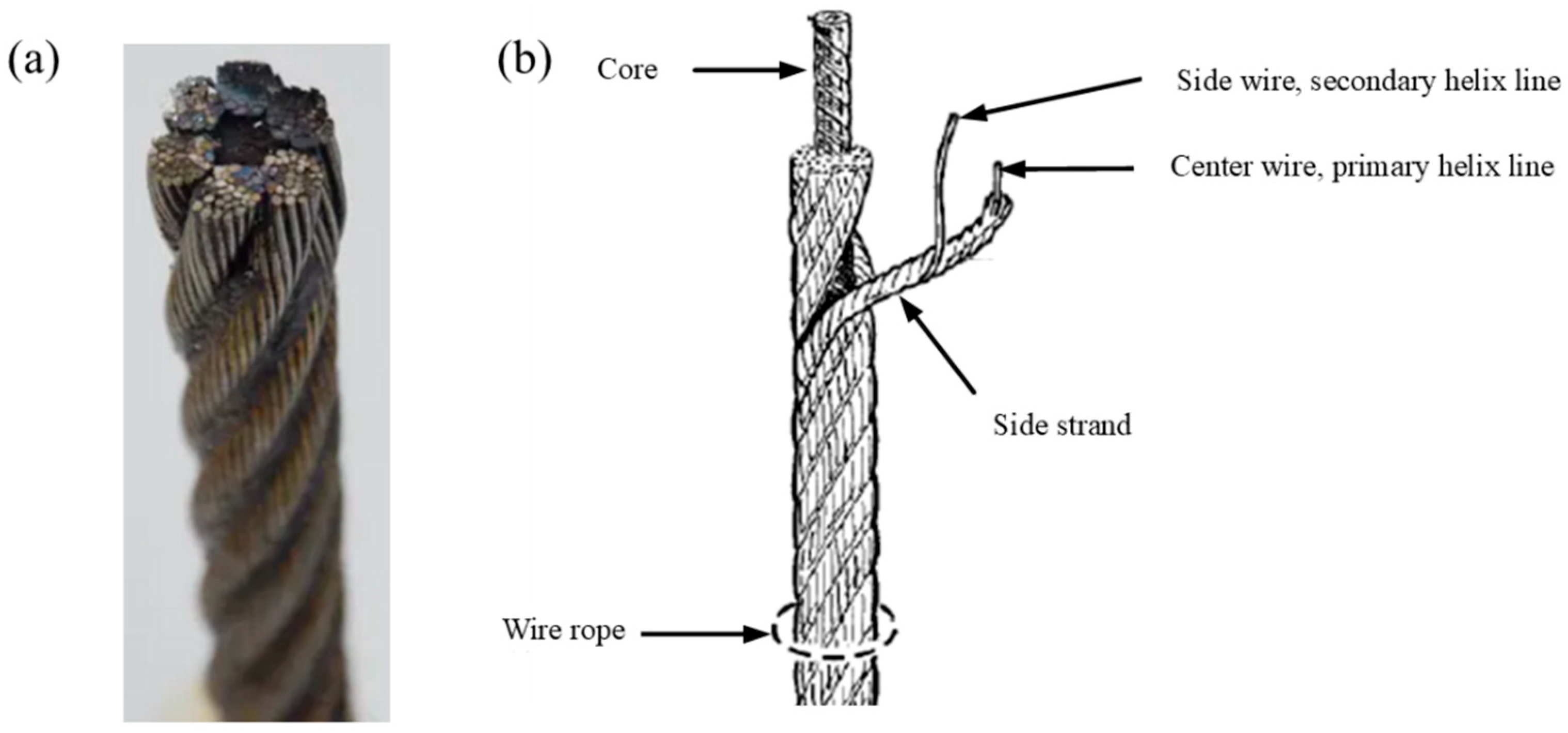
The special rigging wire rope is of the 6 × 31 WS-FC structure, that is, 31 wires of different diameters are layered and helically twisted to form strands, and then these 6 strands are helically twisted around a core to form the rope. Therefore, the rope is composed of a primary helix line and a secondary helix line in space, as shown in
Figure 1.
The key to establishing the three-dimensional model of the steel wire rope is to establish the equation of a single helical line representing the center line of the wire strand and the equation of a second helical line representing the space of 30 side line steel wires wound around the central steel wire of the wire strand.
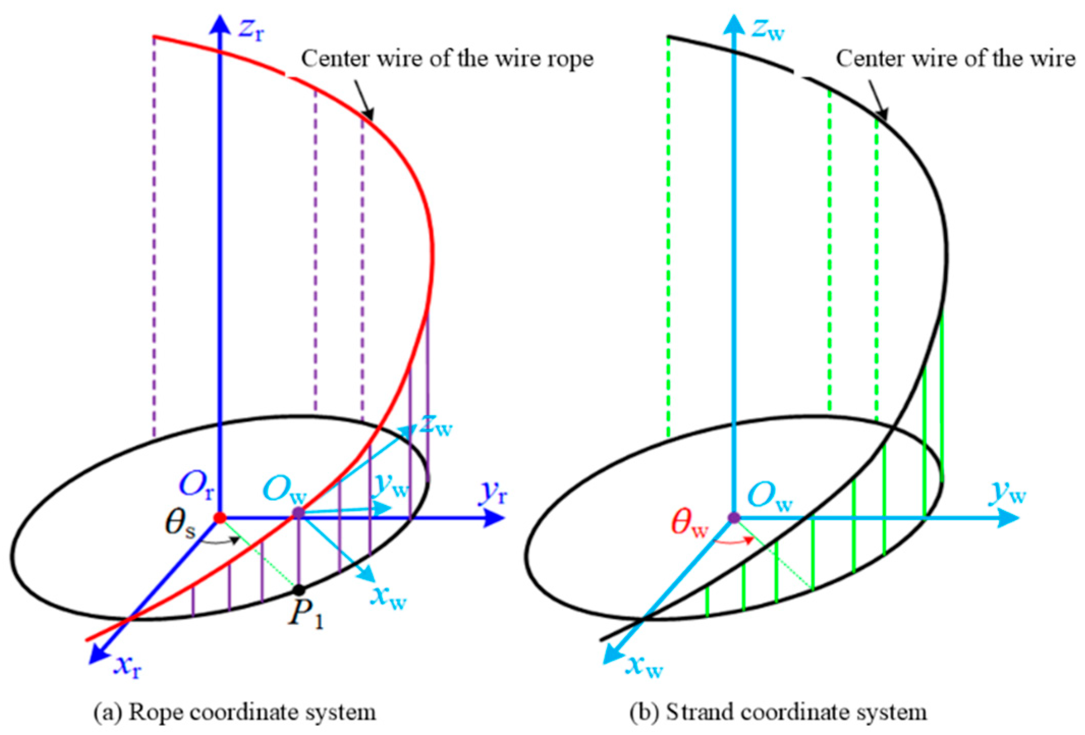
First, establish the right-angled coordinate system
CSOr on the cross-section of the steel wire rope, as shown in
Figure 2a, with the coordinate origin
Or (fixed) located at the center of the cross-section of the steel wire rope, the coordinate axis
zr coinciding with the axis line of the steel wire rope and pointing upwards in the positive direction, and the coordinate plane
xrOryr used to measure the helical angle
θs of the wire strand. Then establish the local coordinate system
CSOw as shown in
Figure 2b, with the coordinate origin
Ow (movable) located on the central line of the wire strand, as shown in
Figure 2a.
P1 is the projection of
Ow on the
xrOryr plane, the direction of the coordinate axis
zw is consistent with the tangent direction at point
Ow on the central line of the wire strand, the positive direction of
zw is the direction of the helix ascent; the coordinate plane
xwOwyw is used to measure the helical angle
θw of the steel wire,
xwOwyw is perpendicular to the
zw axis.
When
zr = 0, the center line of the rope strand intersects with the
xr axis, and at this time
θs = 0. Then, in the entire rope coordinate system
CSOr, the vector equation of the center line of the rope strand is expressed by the following formula:
The parameter expressions on the three components (
xs,
ys,
zs) can be calculated using the following formula:
In the formula, rs represents the first helical radius of the rope strand centerline, and αs represents the twist angle of the rope strand centerline.
Similarly, when
zw = 0,
θw = 0. Then, in the rope strand coordinate system
CSOw, the vector equation of the steel wire centerline is expressed by the following formula:
The parameter expressions on the three components (
xw,
yw,
zw) can be calculated using the following formula:
In the formula, rw represents the first helical radius of the steel wire centerline around the strand axis, and αw represents the twist angle of the steel wire centerline.
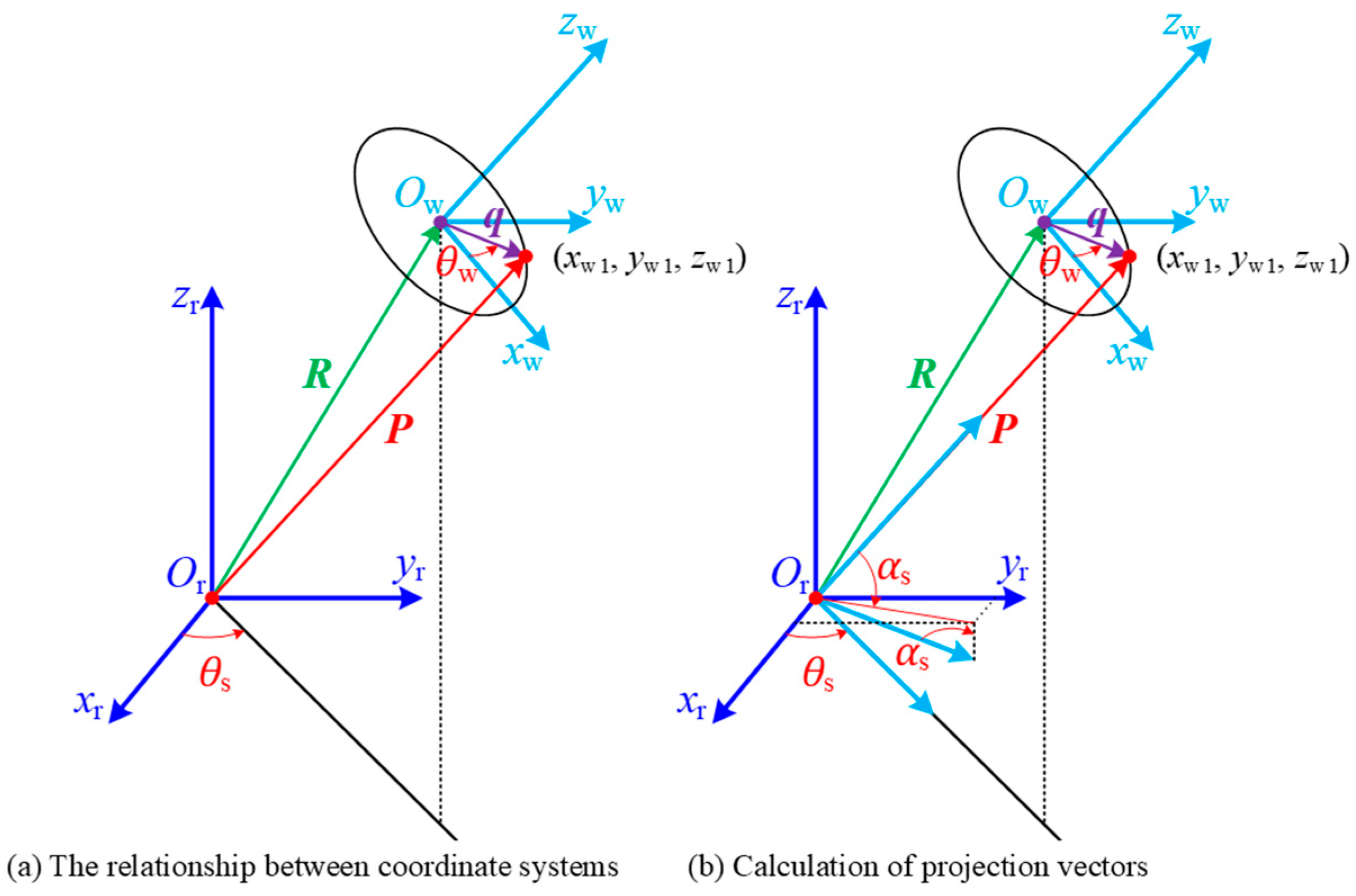
The second helical model is composed of the vector
R defined in the global rope coordinate system
CSOr and the vector
q defined in the coordinate plane
xwOwyw of the ropestrand, as shown in
Figure 3.
Suppose the position vector
P defined in the entire rope coordinate system points to the end point of vector
q (
xw1,
yw1,
zw1), and the point (
xw1,
yw1,
zw1) is also on the center line of the yarn of the rope strand, then the vector
P can be expressed as:
The vector
q located on the coordinate plane
xwOwyw can be expressed in the rope strand coordinate system as:
Since vector
q lies on the coordinate plane, therefore
zw1 = 0. Here, the coordinate components (
xw1,
yw1) can be obtained from Equation (4). Also, since vector
R points to the starting point of vector
q, vector
P can be obtained by vector summation, that is:
Next, we will solve for the projection coordinates of the vector
q defined in the rope fiber coordinate system
CSOw in the entire rope coordinate system
CSOr. Given: (1) The coordinate axis
xw is parallel to the line segment on the coordinate plane
xrOryr that indicates the rotation angle of the rope fiber; (2) The coordinate axis
zw points in the tangential direction of the rope fiber center line, and it has a helical pitch angle (twist angle)
αs; (3)
zw1 = 0. Then, the
xw1 component of the vector
q in the entire rope coordinate system can be expressed as:
According to the theorem of orthogonal projection: For two intersecting lines that are perpendicular to each other, if one of the lines is parallel to a certain projection plane, then the projections of the two lines on that projection plane still reflect the right-angle relationship. Then the projection of the
yw1 component of vector
q in the entire coordinate system can be expressed as:
Therefore, the vector
q can be expressed in the global coordinate system
CSOr as:
Similarly, vector
P can be expressed in the global coordinate system
CSOr as:
After substituting the parameters of the above formula with their respective expressions, the parametric equation of vector
P in the integral coordinate system
CSOr can be obtained. This equation is the mathematical model of the second-order helical line of the wire centerline.
4. Transient Dynamics Analysis
Considering the structure of the wire rope rigging, there are numerous contacts between the wires, and the contact surfaces constantly change during the loading process, featuring strong contact nonlinearity characteristics. Additionally, during the loading process, the rope itself will also undergo significant deformation, causing nonlinear responses of the structure. To enhance computational efficiency and mitigate convergence difficulties arising from strong nonlinearities in the model, an explicit dynamic algorithm was adopted for simulation. This method has been demonstrated to accurately predict the axial, torsional, and bending stiffness of wire ropes [
19].
In this paper, the elastic modulus of the wire in the rigging is 200 GPa, and the Poisson’s ratio is 0.3. The elastic–plastic material parameters used in the simulation are obtained through splitting the steel wire tensile test. The tension, stress, time, and angle in the text are in the normalized unit P.U., where 1 P.U. tension = 0.1 times the minimum breaking force of the wire rope, 1 P.U. stress = the tensile strength of the inner steel wire, 1 P.U. time = twice the time it takes for the tension of the rigging to rise to the maximum value during the impact loading, and 1 P.U. angle = the relative maximum allowable bending angle of the joint to the wire rope design.
4.1. Analysis of the Force on the Rigging Under Axial Impact Load
Based on the established finite element model of the rigging, an axial impact load was applied. Given that the joint exhibits substantially higher macroscopic stiffness compared to the wire rope, all six degrees of freedom of the joint were fully constrained in the simulation. The nodes on the end cross-section of the wire rope were kinematically coupled to the sectional center point. All degrees of freedom of this reference point were restricted except for translation along the axial direction. An axial impact load of 4 P.U. with a loading duration of 10 P.U. was then applied at this center point, as illustrated in
Figure 10.
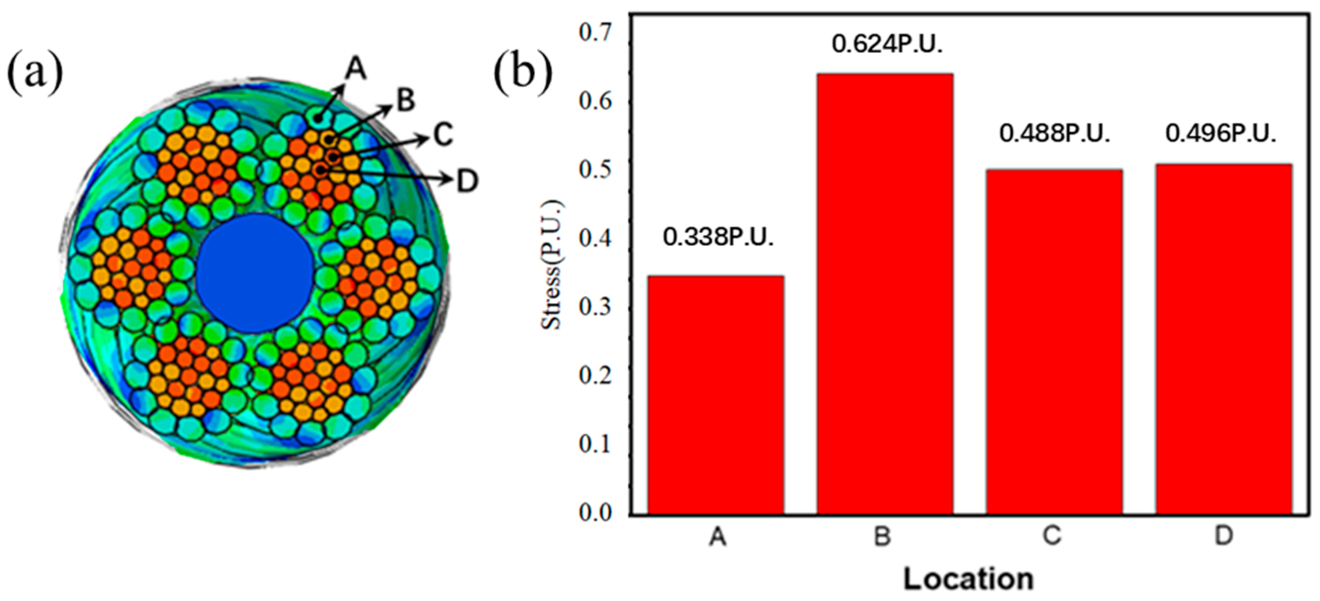
Following the simulation, the mechanical response of the rigging under a 4 P.U. axial impact load (upon load stabilization) is illustrated in
Figure 8 (cross-section of the wire rope) and
Figure 11 (cross-section at the joint root). In
Figure 11, labels A, B, C, and D denote the outer layer, the second outer layer, the inner layer, and the core wire, respectively.
It can be observed that under tensile loading, the maximum stress in the rigging occurs in the second outer layer of the wire rope at the joint root. The peak equivalent stress reaches 0.62P.U., which is 1.8 times greater than that of the outer wire. Stress levels in the inner and core wires are comparable, and the stress distribution across the strand cross-section exhibits an approximately fan-shaped pattern. This phenomenon can be attributed to the following factors: First, due to the larger helical radius of the outer wires compared to the inner wires, the outer wires have a longer effective length over the same rope segment. During tension, the outer wires experience less elongation, resulting in lower stress development. Second, the constraint imposed by the joint induces stress concentration near the contact region, causing the stress distribution to shift toward the joint side. As a result, the second outer layer bears higher stress than both the inner and core wires. Along the length of the rope, significant stress concentration is observed near the joint root due to end effects, while regions farther away show more uniform stress distribution, indicating effective load transfer characteristics of the wire rope.
Further analysis of the stress evolution at locations A, B, C, and D (as indicated in
Figure 12) during axial impact loading is presented in
Figure 13. It was observed that upon impact, the stress in all wires increased abruptly. Among them, the maximum instantaneous stress of the inner layer, the second outer layer, and the core wire reached 0.93 P.U., which was 1.5 times the maximum stress of the steel wires in the stable state. Moreover, the steel wires underwent yielding before reaching the stable state. With the continuous loading, the stress of the steel wires in the corresponding area decreased rapidly and stabilized. This indicates that the impact load is an important form of load causing damage to the rigging.
4.2. Analysis of the Forces Acting on the Rigging Under Tension Bending Loads
For the tension bending load of the rigging, the method of decoupling tension and bending loads is adopted. In this method, the joint end and the axial impact loading are the same. The joint and the steel wire rope inside the joint are subject to rigid constraints, and all nodes are constrained to the center point of the end face close to the steel wire rope direction (P1); the end face node of the steel wire rope is constrained to the center point of the end face (P2), as shown in
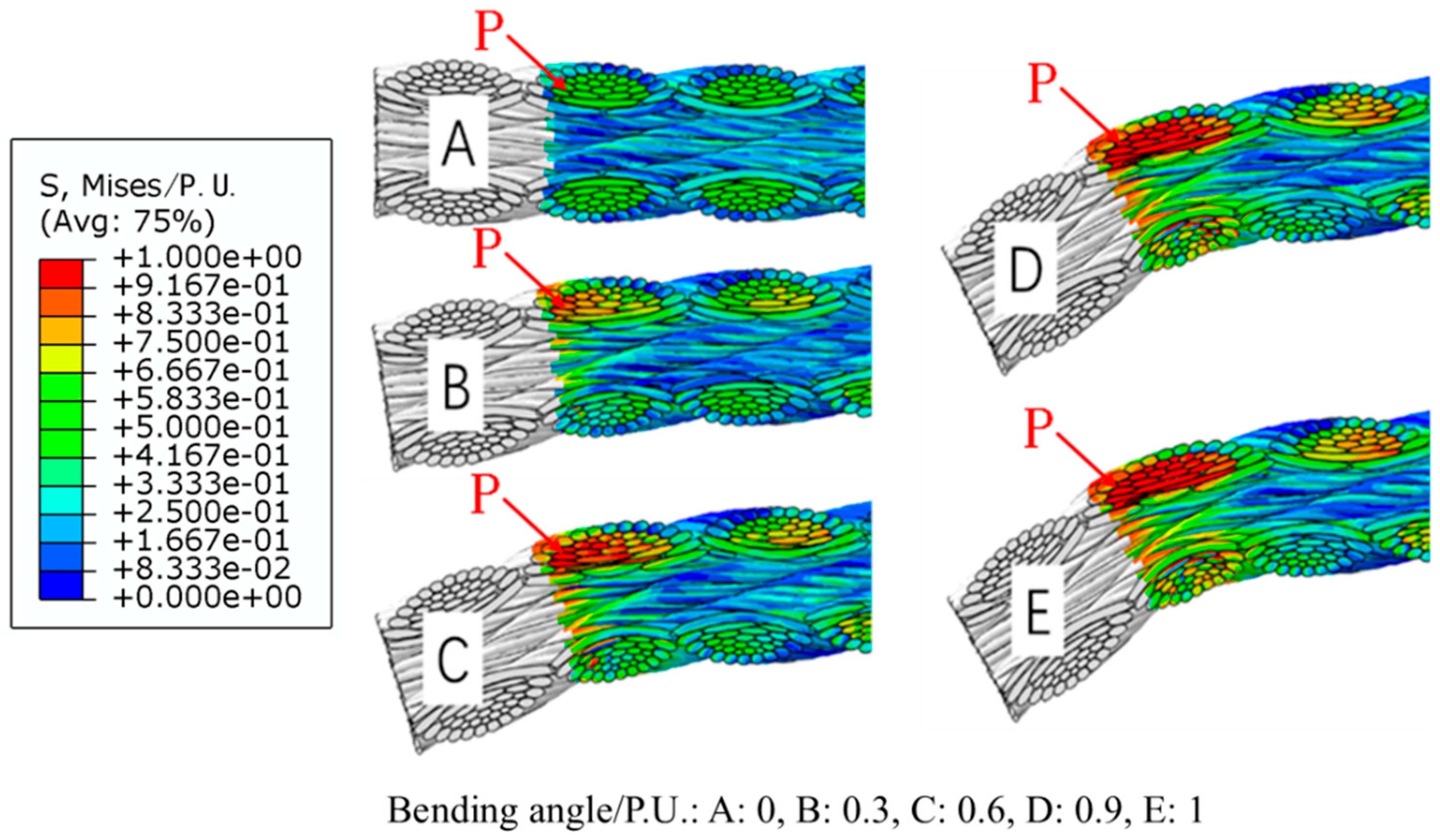
Figure 13. The combined tension-bending loading is applied in two time steps. During the tension application stage, all constraints are applied at point P1, and an axial impact load of 4 P.U. is applied at point P2. During the bending application stage, the tension at point P2 remains constant, and a bending load is applied at point P1 (where the object rotates 1 P.U. around the Z-axis).
Figure 14 shows the stress distribution of the rigging under tension bending load. It can be seen that the maximum stress still exists on the outermost layer of steel wires, at 0.97 P.U. However, at the root of the joint, the stress distribution on the steel wire rope has significantly changed compared to when it only bears axial load. The stress distribution on the upper and lower sections of the steel wire is no longer uniform, and the stress on the side of the steel wire rope that is under tension during bending has significantly increased; in the length direction of the steel wire rope, as the distance from the joint increases, the maximum stress of the entire cross-section of the rope gradually decreases, and the stress distribution becomes more uniform. This is because a "fixed end" constraint similar to casting was adopted between the joint and the steel wire rope, which has extremely high stiffness. The positions of the steel wires on the cross-section of the joint area are relatively fixed. However, when the rigging bears a large tension bending load, the steel wires away from this cross-section can automatically adjust their positions to better bear the load, while the positions of the steel wires on the cross-section of the joint area are rigidly constrained and fixed, so there is inevitably a large force imbalance.
The curves showing the stress and strain of each layer of steel wires on the tensioned side of the joint root in
Figure 14 (the steel wire at point P in the figure) as a function of the bending angle are shown in
Figure 15.
It can be seen that as the bending angle of the joint of the steel wire rope increases, the stress of each layer of steel wires on the tension side of the joint root increases rapidly. When the bending angle exceeds 0.15 P.U., the stress gradually slows down as the bending angle increases. This is because at this time, the steel wires have undergone yielding. As the strain increases, the stress no longer increases linearly. The strain of each layer of steel wires changes in an opposite trend to the stress with the change of the bending angle: when the bending angle is not more than 0.15 P.U., the strain of each steel wire changes little. When the bending angle is greater than 0.15 P.U., the strain of the steel wire approximately continuously increases linearly. This is because when the bending angle is not more than 0.15 P.U., the steel wire has not yet yielded, and its deformation is mainly elastic deformation. The steel wire material relies on its own strength to resist the bending deformation; when the bending angle is greater than 0.15 P.U., the steel wire yields, and the plastic deformation increases rapidly. Among them, the plastic deformation of the outer layer steel wire is greater than that of the inner layer steel wire, because the outer layer steel wire is farther from the bending rotation center, and after bending, a larger deformation is required to coordinate.
