Article

Numerical Study on the Effects of Surface Shape and Rotation on the Flow Characteristics and Heat Transfer Behavior of Tandem Cylinders in Laminar Flow Regime

1
Institute of Naval Architecture and Ocean Engineering, Ningbo University, Ningbo 315211, China
2
Faculty of Maritime and Transportation, Ningbo University, Ningbo 315211, China
3
Yungongfang Intelligent Technology Co., Ltd., No. 9 Chenghai Road, Meishan Free Trade Port Zone, Ningbo 315211, China
*
Authors to whom correspondence should be addressed.
These authors contributed equally to this work.
Modelling 2025, 6(4), 132; https://doi.org/10.3390/modelling6040132
Submission received: 29 August 2025 / Revised: 4 October 2025 / Accepted: 9 October 2025 / Published: 17 October 2025

Abstract

Tandem cylinders, widely used in heat exchangers, water storage units, and electronic cooling, require optimized flow and heat transfer to enhance engineering performance. However, the combined effects of various factors in tandem configurations remain insufficiently explored. This study proposes an innovative approach that integrates multiple parameters to systematically investigate the influence of surface pattern characteristics and rotational speed on the fluid dynamics and heat transfer performance of tandem cylinders. Numerical simulations are conducted to evaluate the effects of various pattern dimensions (w/D = 0.12–0.18), surface shapes (square, triangular, and dimpled grooves), rotational speeds (|Ω| ≤ 1), and frequencies (N = 2–10) on fluid flow and heat transfer efficiency at Re = 200. The study aims to establish the relationship between the complexity of the coupling effects of the considered parameters and the heat transfer behavior as well as fluid dynamic variations. The results demonstrate that, under stationary conditions, triangular grooves exhibit larger vortex structures compared to square grooves. When a positive rotation is applied, coupled with increases in w/D and N, square grooves develop a separation vortex at the front. Furthermore, the square and dimpled grooves exhibit significant phase control capabilities in the time evolution of lift and drag forces. Under conditions of w/D = 0.12 and w/D = 0.18, the CL of the upstream cylinder decreases by 17.2% and 20.8%, respectively, compared to the standard smooth cylinder. Moreover, the drag coefficient CD of the downstream cylinder is reduced to half of the initial value of the upstream cylinder. As the surface amplitude increases, the CD of the smooth cylinder surpasses that of the other groove types, with an approximate increase of 8.8%. Notably, at Ω = −1, the downstream square-grooved cylinder’s CL is approximately 12.9% lower than that of other groove types, with an additional 6.86% reduction in amplitude during counterclockwise rotation. When N increases to 10, the C ¯ D of the upstream square-grooved cylinder at w/D = 0.18 decreases sharply by 20.9%. Conversely, the upstream dimpled-groove cylinder significantly enhances C ¯ p at w/D = 0.14 and N = 4. However, the upstream triangular-groove cylinder achieves optimal C ¯ p stability at w/D ≥ 0.16. Moreover, at w/D = 0.18 and N = 6, square grooves show the most significant enhancement in vortex mixing, with an increase of approximately 42.7%. Simultaneously, the local recirculation zones in dimpled grooves at w/D = 0.14 and N = 6 induce complex and geometry-dependent heat transfer behaviors. Under rotational conditions, triangular and dimpled grooves exhibit superior heat transfer performance at N = 6 and w/D = 0.18, with TPI values exceeding those of square grooves by 33.8% and 28.4%, respectively. A potential underlying mechanism is revealed, where groove geometry enhances vortex effects and heat transfer. Interestingly, this study proposes a correlation that reveals the relationship between the averaged Nusselt number and groove area, rotational speed, and frequency. These findings provide theoretical insights for designing high-efficiency heat exchangers and open up new avenues for optimizing the performance of fluid dynamic systems.

1. Introduction

The investigation of fluid flow and heat transfer behavior around cylinders is currently a highly focused research topic. Extensive studies have expanded upon this foundation, encompassing rotating cylinders and various surface shapes, such as rectangular [1], square [2], trapezoidal [3], elliptical [4,5,6], D-shaped or blunt bodies [7,8]. Analyses have shown that rotation can effectively suppress unstable fluctuations in the wake region, particularly demonstrating significant effects in reducing drag and heat transfer, enhancing lift, and optimizing noise [9,10,11]. Furthermore, the development and evolution of wake structures are significantly influenced by different surface characteristics, especially in terms of vortex shedding, aerodynamic parameters, and heat transfer performance. Additionally, the arrangement of cylinders has also garnered considerable attention. Consequently, related examinations hold substantial importance for practical engineering applications, such as wind turbine blades, marine risers, and chip cooling [12,13].
Extensive investigations have been conducted on stationary, single smooth cylinders [14,15,16,17,18] to optimize drag coefficients and heat transfer rates; researchers have made significant advancements by modifying the surface shapes of the cylinders [19]. For example, inspired by the morphology of cacti, grooved cylinders have garnered considerable attention [20,21,22,23]. These grooves are believed to effectively control the wake structure behind the cylinder, reducing fluctuating pressure. Yamagishi [24] utilized numerical simulation methods to study the flow characteristics around cylinders with different groove shapes. The results indicated that cylinders with triangular grooves exhibited approximately 15% lower drag coefficients compared to those with semicircular grooves. Afroz and Sharif [25] investigated the laminar cross-flow around smooth cylinders and cylinders with longitudinal grooves (V-shaped, U-shaped and rectangular grooves) within a low Reynolds number range (50 to 300). The study indicates that at Reynolds numbers of 200 and 300, the average drag coefficient of U-grooved cylinders decreased by approximately 13% and 10%, respectively, with a 30% reduction in viscous drag. Moreover, the grooves on the cylinder surface delayed the separation point and significantly reduced drag at high Reynolds numbers. The effectiveness of the grooves was closely related to the position, with the most effective location being around 80 degrees from the front stagnation point [26]. Derakhshandeh and Gharib [27] and Li et al. [28] summarized the impact of protrusions on the flow field, indicating a decreasing trend in drag coefficients and an increase in average Nusselt numbers. Sharma and Barman [29] conducted numerical simulations to study the flow characteristics of slotted cylinders within a Reynolds number range of 60 to 180. The results showed that slotted cylinders suppressed periodic vortex shedding across all Reynolds numbers, with surface vorticity increasing by 16% to 23%. At Reynolds numbers greater than 70, the total drag coefficient and Strouhal number of slotted cylinders were lower than those of smooth cylinders.
Subsequently, other scholars further investigated the effects of groove inclination angles on flow field characteristics and heat transfer performance. Canpolat [19] experimentally studied the impact of different angular positions (θ = 0–150°) of a single longitudinally grooved cylinder on flow separation. It was found that, for all considered groove depths, the Strouhal number (St = fv D/U, where fv represents the vortex shedding frequency) peaked at θ = 90°. Derakhshandeh and Gharib [30] conducted numerical simulations to examine the flow characteristics of cylinders with various groove shapes (square, triangle and dimple) within a Reynolds number range of 50–200. The results indicated that the drag coefficient of a triangular-grooved cylinder at θ = 45° decreased by 100%. Additionally, Derakhshandeh et al. [31] explored the force coefficients and heat transfer properties of grooved cylinders at different angular positions (θ = 0°, 30°, 45°, 60° and 90°) under Re ≤ 200. The findings revealed that the triangular groove at θ = 45° exhibited the lowest drag coefficient and significantly enhanced the Nusselt number in the wake region. Moreover, at θ = 0°, the Nusselt number showed opposite trends at Re = 50 and Re = 200. Priyadarsan and Afzal [32] performed numerical simulations to investigate the hydrodynamic characteristics of single-groove (dimple, square and triangle) cylinders at low Reynolds numbers. The results demonstrated that a square groove at 90° was most effective in reducing drag and lift, while positions at 120° and 150° led to an increase in total drag. Analysis of pressure coefficients and separation angles indicated that grooves at 90° could delay separation, whereas grooves at 60° caused earlier boundary layer separation.
The aforementioned studies predominantly focus on flow characteristics under static conditions. The initial proposition of using rotating cylinders to reduce drag was made by scholars [33]. They discovered that for Reynolds numbers over 1.0 × 10⁵, the drag coefficient of grooved cylinders varied with an increasing rotation rate ratio α, regardless of the groove depth. Mittal and Kumar [34] conducted numerical simulations to investigate the flow characteristics of rotating cylinders in uniform flow (0 ≤ α ≤ 5). The study revealed that vortex shedding occurred when α < 1.91, with the flow becoming steady at higher rotation rates. However, within the range of 4.34 < α < 4.70, the flow became unstable again, exhibiting single-sided vortex shedding. Subsequently, Paramane and Sharma [35] numerically examined the forced convection heat transfer behavior of cylinders over a broader range of rotation rates (0 ≤ α ≤ 6) and Reynolds numbers (20–160). The results indicated that rotation facilitates drag reduction and suppresses heat transfer.
Interestingly, the presence of downstream cylinders introduces additional complexity to the flow field and heat transfer phenomena. When Re = 200, Ansari et al. and [36] Darvishyadegari [37,38] explored the effects of the rotation of two tandem cylinders on fluid dynamics and heat transfer. The studies revealed that counter-rotating cylinders achieved optimal heat transfer efficiency at a specific rotation speed [37]; however, co-rotating cylinders resulted in diminished heat transfer performance [36]. Furthermore, at high rotation speeds, the Nusselt number distribution between the two cylinders was relatively uniform [38]. Rastan et al. [39] conducted numerical analyses to investigate the influence of Reynolds number (Re), spacing ratio (S*), and rotation rate (α) on the fluid dynamics, Strouhal number, and convective heat transfer effects of two rotating cylinders. This study particularly focused on the impact of these parameters on wake dynamics and heat transfer behavior. The results indicated that cylinder rotation significantly affects fluid dynamics, revealing four flow regimes: steady flow, alternating shedding flow, single-rotating bluff body flow, and counter-rotating flow. Recently, the flow characteristics of tandem single-grooved cylinders (square, triangle and dimple) at different inclination angles (θ = 0°, 45° and 90°) and Reynolds numbers (75–200) were also investigated [40], reporting changes in vorticity and force coefficients. Based on this, studies [41,42] have further supplemented the research on heat transfer aspects [43,44].
According to the literature review, the majority of studies have focused on single-grooved rotating cylinders, tandem smooth rotating cylinders, and grooved cylinders under static conditions. Although previous research has explored the dynamics within single grooved regions, the flow and heat transfer characteristics of multiple grooves under rotating conditions remain unclear. Additionally, while some studies have investigated different groove types (square, triangle and dimple), the corresponding variations in scale ratio have not been thoroughly reported. Similarly, although three groove types are mentioned, the influence of grooves between two cylinders has not been demonstrated. Therefore, it is necessary to investigate the scale ratio factors under rotating and multiple-groove conditions. In this study, global parameters such as the Strouhal number, Nusselt number (Nu), time averages, surface averages, and root mean square values (denoted by over bar ‘-’, angle brackets ‘< >’, and prime symbol ‘ ‘ ’, respectively) are mentioned. Notably, this study fills the specific research gap, enabling comparative analysis.
This study numerically investigates the effects of pattern characteristics and rotational speed on the flow and heat transfer of tandem cylinders under laminar conditions (Re = 200). Although both this study and the comparative literature [45,46,47,48] employ numerical simulation methods, the present work introduces a research approach that incorporates multiple parameter interactions. This approach facilitates a deeper understanding of the flow and heat transfer phenomena in patterned rotating tandem cylinders, thus providing a more comprehensive analysis. The considered case models, as well as the single and tandem smooth cylinder models, are used as benchmark cases for grid independence testing and model accuracy verification. Subsequently, the numerical analysis is extended to investigate the flow and heat transfer characteristics of rotating tandem cylinders with different groove scale ratios (w/D), frequencies (N) and rotation rates (−1 ≤ Ω ≤ 1). The configuration proposed in this study has potential applications in various scenarios, such as heat exchangers, tandem chimneys, cylindrical components and chips on electronic device motherboards, water storage units, and microfluidic devices. The diversity of these applications underscores the necessity of thoroughly examining the flow structures of the specific configuration.

2. Numerical Model

2.1. Physical Geometry

The configuration of the computational domain is illustrated in Figure 1a, where a pair of tandem cylinders is exposed to a uniform incoming flow. Both cylinders have identical dimensions, with the diameter denoted as D. The spacing between the cylinders is defined as L, which is normalized as L* = L/D. The origin of the coordinate system is located at the center of the patterned upstream cylinder, while the surface of the downstream cylinder is smooth. The distances from the upstream and downstream cylinders to the inlet and outlet are both 40D. The lateral dimensions are symmetric about the horizontal centerline of the cylinders, resulting in a 5% blockage ratio. Consequently, the sidewall effects [49,50,51,52,53,54], blockage ratio [55,56,57] and outlet pressure can be effectively excluded from influencing the flow patterns and thermal characteristics.
The rotational motion of the upstream and downstream cylinders is co-rotating, and its angular velocities are constrained within the specified range (−1 ≤ Ω ≤ 1). Although previous studies [39] have suggested that higher rotational speeds require a larger computational domain, the method proposed in this study meets the requirements for both accuracy and efficiency, aligning with the results. The incoming flow velocity (U) and temperature (T) are kept constant, but the wall temperatures (Tw) of both cylinders are set higher than T to ensure effective heat transfer [58].
The variation in different groove shapes (square, triangle, and dimple) depends on the width-to-diameter ratio (w/D), the depth-to-width ratio (h/w = 1) [42], and the frequency (N) [Figure 1b–d], where h and w represent the groove depth and width, respectively. The w/D and N increase monotonically in intervals of 0.02 and 2, respectively, leading to a symmetrical distribution of surface patterns. Consequently, this study encompasses various case combinations, resulting in multiple configurations approximating wave crests and troughs.

2.2. Governing Equations

Consider a Newtonian fluid with a Reynolds number of 200 flowing past patterned tandem rotating cylinders. The flow is assumed to be two-dimensional incompressible, unsteady, laminar, and characterized by stable thermophysical properties. The relevant variables are presented in dimensionless form to address the modeling problem [59,60,61,62]:
Continuity equation
u * x * + v * y * = 0 .
Momentum equation
u * t * + u * u * x * + v * u * y * = p * x * + 1 R e 2 u * x * 2 + 2 u * y * 2 .
v * t * + u * v * x * + v * v * y * = p * y * + 1 R e 2 v * x * 2 + 2 v * y * 2 .
Energy equation
Θ * t * + u * Θ * x * + v * Θ * y * = 1 R e P r 2 Θ * x * 2 + 2 Θ * y * 2 ,
where Θ * represents the dimensionless temperature. The specific forms of the aforementioned variables are as follows:
x * = x D ,   y * = y D ,   u * = u U ,   v * = v U ,   p * = p ρ U 2 ,
Θ * = T T T W T ,   t * = t U D ,   R e = ρ U D μ   and   P r = μ c p K ,
where u and v represent the velocity components in the x and y directions, respectively. p denotes pressure, ρ represents fluid density, T stands for temperature, t denotes physical time, and μ represents the dynamic viscosity. The Prandtl number Pr is taken as 0.71 (air). Additionally, cp represents the specific heat capacity of the fluid, and K denotes the thermal conductivity of the fluid.
In this study, the fluctuating lift coefficient (CL), drag coefficient (CD), pressure coefficient (Cp), and dimensionless rotational speed (Ω) are defined as follows [63]:
C L = 2 F L ρ D U 2 ,
C D = 2 F D ρ D U 2 ,
C P = P c P ρ U 2 2 ,
Ω = U α R
where FL and FD represent the total lift and drag forces per unit length acting on the cylindrical surface in the flow direction, respectively, Pc denotes the pressure on the cylindrical surface, and P represents the pressure in the free stream. Furthermore, the parameters related to thermal performance are provided as follows:
The local Nusselt number N u β on the surface of the rotating cylinder is evaluated by the following equation:
K T n | w = h β ( T w T ) ,
N u β = h β D / K ,
where h represents the convective heat transfer coefficient, β denotes the polar angle of the cylinder, and n, the unit vector normal to the surface of the cylinder, is expressed as:
n = x e x + y e y x 2 + y 2 = n x e x + n y e y ,
where ex and ey are the unit vector components in the x and y-directions, respectively.
The weighted average Nusselt number integrated along the surface area of the cylinder is given by:
< N u > = 1 2 π 0 2 π N u β d β .
Equation (15) can be expressed as a function of groove area, frequency and rotational speed and is given as:
< N u > = f ( A , N , Ω )
When the surface of the cylinder is altered, both the Nusselt number and drag in the flow field change accordingly. Therefore, to quantitatively describe the relationship between heat transfer and pressure drop, the thermal performance index (TPI) has been introduced [64,65,66]. The TPI is defined as follows:
T P I = N u / N u 0 Δ P / Δ P 0
Here, ΔP represents the pressure drop in the flow field, while ΔP0 and Nu0 denote the baseline pressure drop and the average Nusselt number for the tandem smooth cylinders, respectively.
In addition, the empirical formula for calculating the Nusselt number (Nu) is provided in the existing literature [67,68,69]:
Žukauskas correlation:
N u = 0.51 R e 0.5 .
Knudsen and Katz correlation:
N u = 0.683 R e 0.466 P r 1 / 3 .
Churchill and Bernstein correlation:
N u = 0.3 + 0.62 R e 1 / 2 P r 1 / 3 [ 1 + ( 0.4 / P r ) 2 / 3 ] 1 / 4 1 + R e 282000 5 / 8 4 / 5 .

2.3. Numerical Details and Boundary Conditions

In this study, the partial differential Equations (1)–(4) are solved using a commercial software package based on the finite volume method (ANSYS Fluent 2019R3). A pressure-based solver is selected as the solution strategy, and the semi-implicit method for pressure linked equations (SIMPLE) algorithm is employed to handle the pressure-velocity coupling. The second-order upwind scheme and the second-order central differencing scheme are employed for the discretization of the convective and diffusive terms, respectively. Temporal discretization is carried out using a first-order implicit forward scheme [70] to enhance computational efficiency. The simulation process continues until the residuals meet the convergence criteria: 10−6 for continuity and momentum, and 10−8 for energy.
In the study of fluid flow over tandem rotating cylinders with varying surface patterns, the interaction between the cylinders and the surrounding fluid induces continuously changing interfaces, presenting challenges for the calibration of the numerical model. Therefore, the sliding mesh method (SMM) is introduced to address the interface variation. The SMM technique divides the computational domain into two regions: (1) stationary region; (2) rotating region. A larger circular area surrounding the patterned rotating cylinders is designated as the rotating mesh region, while the remaining area constitutes the stationary mesh region. The rotating and stationary mesh regions interface at a boundary where data is exchanged, allowing relative motion between the two regions without the need for shared nodes [Figure 2b].
A non-uniform mesh spacing is applied near the grooved structures on the cylinder surface to better capture the viscous boundary layer. The first layer of grid spacing is set to 0.01D [17,20], with a mesh growth rate of 1.12, gradually expanding toward the outer boundaries of the computational domain. Notably, to minimize errors, the mesh sizes at the interface should be consistent. Specifically, the grid sizes at the interface between the dynamic rotating region and the stationary region are 1.39 × 10⁻⁴ and 1.26 × 10⁻⁴, respectively. Furthermore, as the grid expands at a specified growth rate, the maximum grid size is limited to 3.53 × 10⁻³ to prevent excessive coarsening of the grid. Additionally, the geometry and mesh are generated using SolidWorks 2020 and Fluent Meshing 2019R3, respectively. The flow is initialized at t* = 0 using the inlet velocity field as the initial condition for the computational domain, where u* = 1, T* = 1, v* = 0, and p* = 0.
To solve the governing equations, the necessary boundary conditions are set as follows: a uniform inflow velocity and temperature are applied at the inlet boundary (The inlet velocity is determined using the Re formula. The inlet temperature is set to 293.5 °C, which is approximately 15% lower than the temperature of two cylinders configuration), while Neumann boundary conditions are imposed for all variables at the outlet boundary. The far-field boundary is configured as adiabatic, frictionless, and impermeable. The cylinder surface is subjected to no-slip and constant temperature conditions (see Table 1).

3. Validation of Numerical Code

To ensure the reliability and applicability of the results in this study, it is essential to conduct grid independence tests and method validation before introducing a large number of cases. This can be achieved by comparing the results with experimental data and numerical results from the published literature. Consequently, the feasibility of the methodology employed in this study can be further confirmed.

3.1. Grid Independence Study

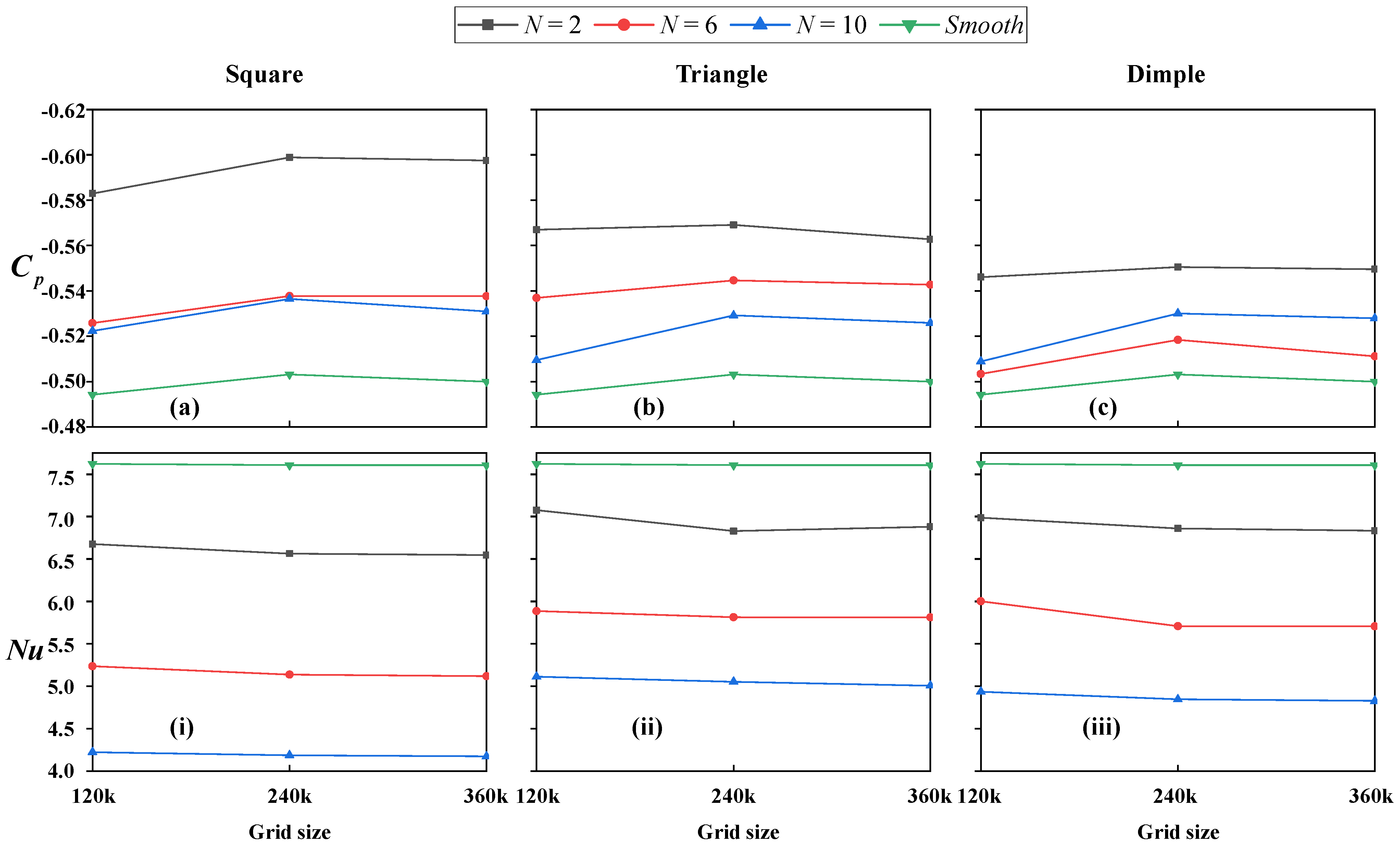
After defining the computational domain, the optimal meshing strategy is further considered. This study conducts tests on three groove shapes (square, triangle and dimple) at different frequencies (N = 2, 4, 6), maintaining a constant w/D = 0.12, with a smooth cylinder serving as the reference. Three types of meshes are employed: coarse mesh (CG = 120 k), medium mesh (MG = 240 k), and fine mesh (FG = 360 k). The test data are summarized in Figure 3 and Figure 4.
The results indicate that when the mesh is refined from MG to FG, the deviations for the square and triangular grooves are both less than 3%. In contrast, the dimpled groove shows even smaller deviations relative to the smooth cylinder, not exceeding 1.4% (see Figure 3). Moreover, the Cp shows a notable variation of approximately 4.2% when transitioning from the CG to the MG, while the change from MG to the FG remains mild, below 0.53%. A similar trend is also observed in the evolution of the Nu with increasing grid resolution. Interestingly, while less influential than the rectangular groove, triangular and dimpled grooves show consistent trends across grid levels (see Figure 4). This consistency indicates that the numerical results are essentially converged and free from significant numerical artifacts. Considering both computational time and efficiency, MG is identified as the optimal strategy [see Figure 2a].
Given that the study involves tandem rotating configurations with surface patterns, simulations are performed using twice the MG mesh to ensure accuracy. Additionally, based on the minimum mesh size (Gridmin = 2.03 × 10⁻⁵) and the Courant number ( C F L = U Δ t / Δ x < 1 ), a time step of 0.001 s is chosen to meet the computational demands of the extensive case studies.

3.2. Parameter Validation

The numerical code is validated by comparing the results for a single stationary and rotating cylinder at Re = 100 and 200 with data from the published literature (see Table 2 and Table 3). The results show that the measured time-averaged drag coefficient ( C ¯ D ), peak lift coefficient (CL,max) and Strouhal number are in good agreement with numerical results, experimental data and analytical solutions. Moreover, the average Nusselt number results presented in Table 3 exhibit a deviation of no more than 1% from the literature data [70], whether at Re = 100 or Re = 200.
To enhance the credibility of the research methodology, this study further investigates the data for a single stationary cylinder and tandem smooth cylinders within −1 ≤ Ω ≤ 1 at different Re. The results are then compared with published numerical and experimental data (Figure 4 and Figure 5). It is evident that at Re = 100, the pressure coefficient distribution aligns perfectly with the results of Rastan et al. [39]. It also closely follows the trend observed in the experimental data by Thom [79] [Figure 5a]. At Re = 200, the pressure coefficient distribution trends are highly consistent with previous studies [79,80]. Although there are some deviations from the conclusions of Mittal and Kumar [34], likely due to differences in the computational domain and solution methods, these results still provide a solid basis for validating the accuracy of this study [Figure 5b].
Figure 6 presents the parameter results as functions of rotational speed for tandem smooth cylinders at Re = 100 and 200. Subscripts 1 and 2 represent the upstream and downstream cylinders, respectively. The obtained force parameters closely follow the trends reported in the literature [39]. Figure 6c shows that, although the < N ¯ u > for the upstream and downstream cylinders differs slightly from the results of Rastan et al. [39], it generally aligns well with the trend observed in the literature. This supports the applicability and reliability of the proposed method.
In summary, this study concludes that the proposed parameter measures effectively meet the accuracy and validity requirements for validation.

4. Results and Discussion

4.1. Flow Characteristics

4.1.1. Streamlines

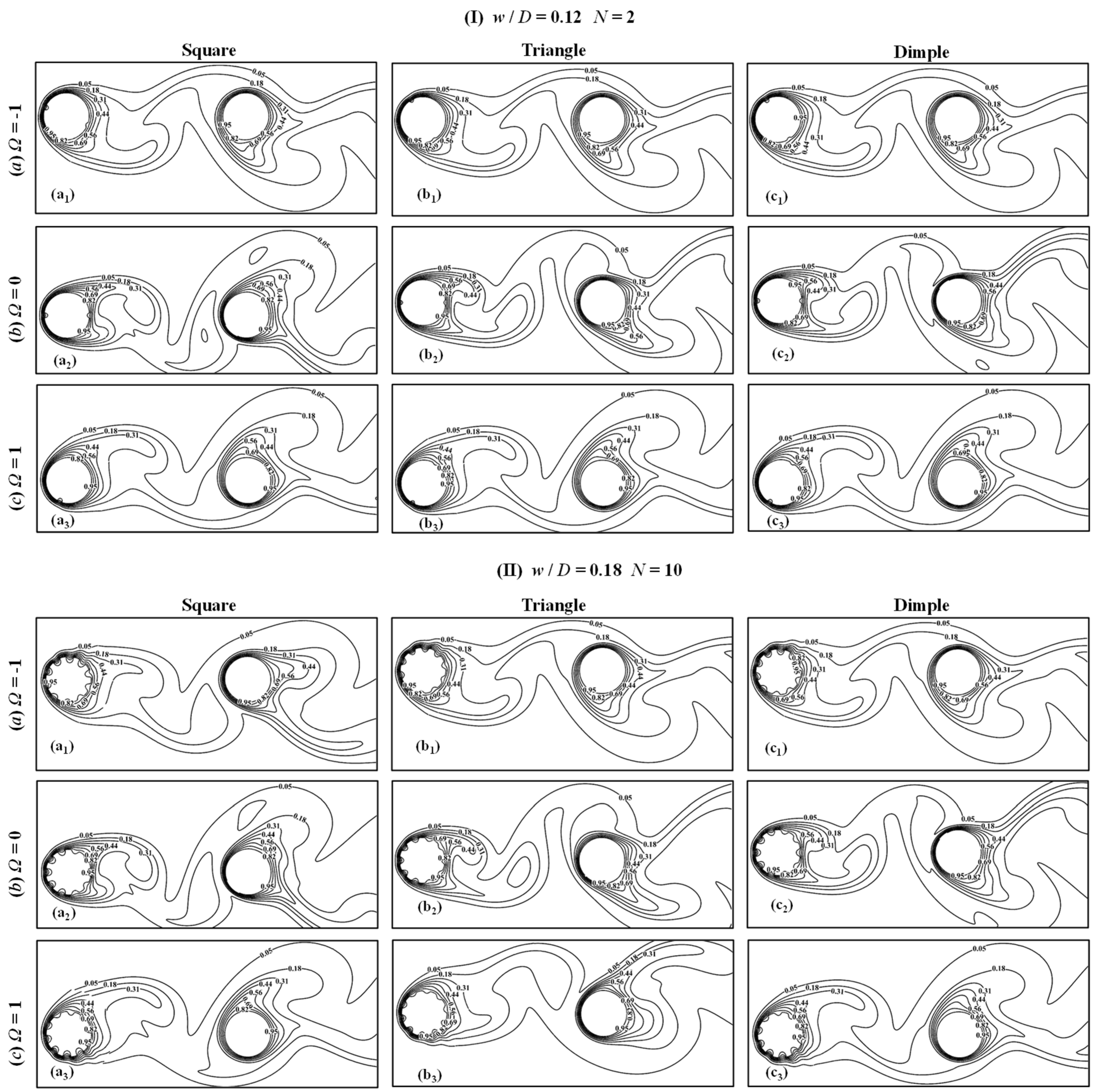
Figure 7 presents the extreme performance under w/D = 0.12 and 0.18, N = 2 and 10, groove types (square, triangle and dimple), and Ω = −1, 0 and 1. All streamline structures are obtained under steady periodic conditions.
To further analyze the influence of different groove shapes and Ω on the flow distribution around the cylinder, the streamline distribution for w/D = 0.12 and N = 2 is shown (see Figure 7I). The results indicate that, under Ω = −1 and 1, the Coriolis force predominantly governs vortex formation under rotational conditions. Furthermore, the streamline distribution is symmetric with respect to the horizontal line, regardless of groove type [see Figure 7I(a,c)]. This indicates that under rotational conditions, the Coriolis force stabilizes the flow field through inertial effects. Furthermore, it reduces the direct influence of various groove geometries on the flow field, leading to a more uniform flow. When Ω = 0, the vortex distribution changes significantly [see Figure 7Ib]. The triangular groove exhibits the largest wake vortex core, whereas the square groove has the smallest. This indicates the square groove’s capacity to suppress wake instability and suggests that a smaller groove area is more conducive to flow field stability. Recirculation zones are observed for all groove types, resulting from fluid entrapment. In the square groove, the recirculation zone at the front stagnation point is larger than that at the rear surface. This difference may be attributed to its deeper recess and the stronger fluid impingement at the leading edge, thereby influencing the flow characteristics.
As the surface pattern amplitude and N increase, new recirculation regions appear above the troughs (see Figure 7II). These recirculation regions are relatively small, primarily due to the deceleration of fluid at the crest region and acceleration in the trough region. The size of these recirculation zones is closely related to the groove type and variations in w/D (see Figure 7II). This suggests that the geometric characteristics of the grooves significantly influence the flow field. Low pressure drives recirculation in the troughs, while weakened momentum exchange at the crests results in flow deceleration. By comparing Figure 7Ib,IIb, it can be observed that as w/D increases, the size of the recirculation zone enlarges, indicating that the enhancement of geometric amplitude promotes the evolution of wake vortices. Unlike Figure 7Ib, Figure 7IIb reveals the formation of a fore-separation vortex in the wake region of the downstream cylinder. This indicates that under rotational conditions, the square groove design shifts the separation point upstream, enhances recirculation, and induces partial vortices. This phenomenon may be related to the uniformity of the square groove edges concentrating local velocity gradients, which in turn induces strong secondary vortices in the wake flow. Notably, only in the case of the square groove with Ω = 1 is a front separation vortex observed, and this vortex appears at the crest. Interestingly, the flow in the dimpled groove exhibits relatively stable behavior at both Ω = −1 and Ω = 1, whereas the opposite is observed in the square groove. This indicates that the curved structure of the dimple grooves can reduce separation intensity and weaken recirculation effects. The curvature design facilitates smooth fluid flow, preventing turbulence excitation.

4.1.2. Drag and Lift Coefficients

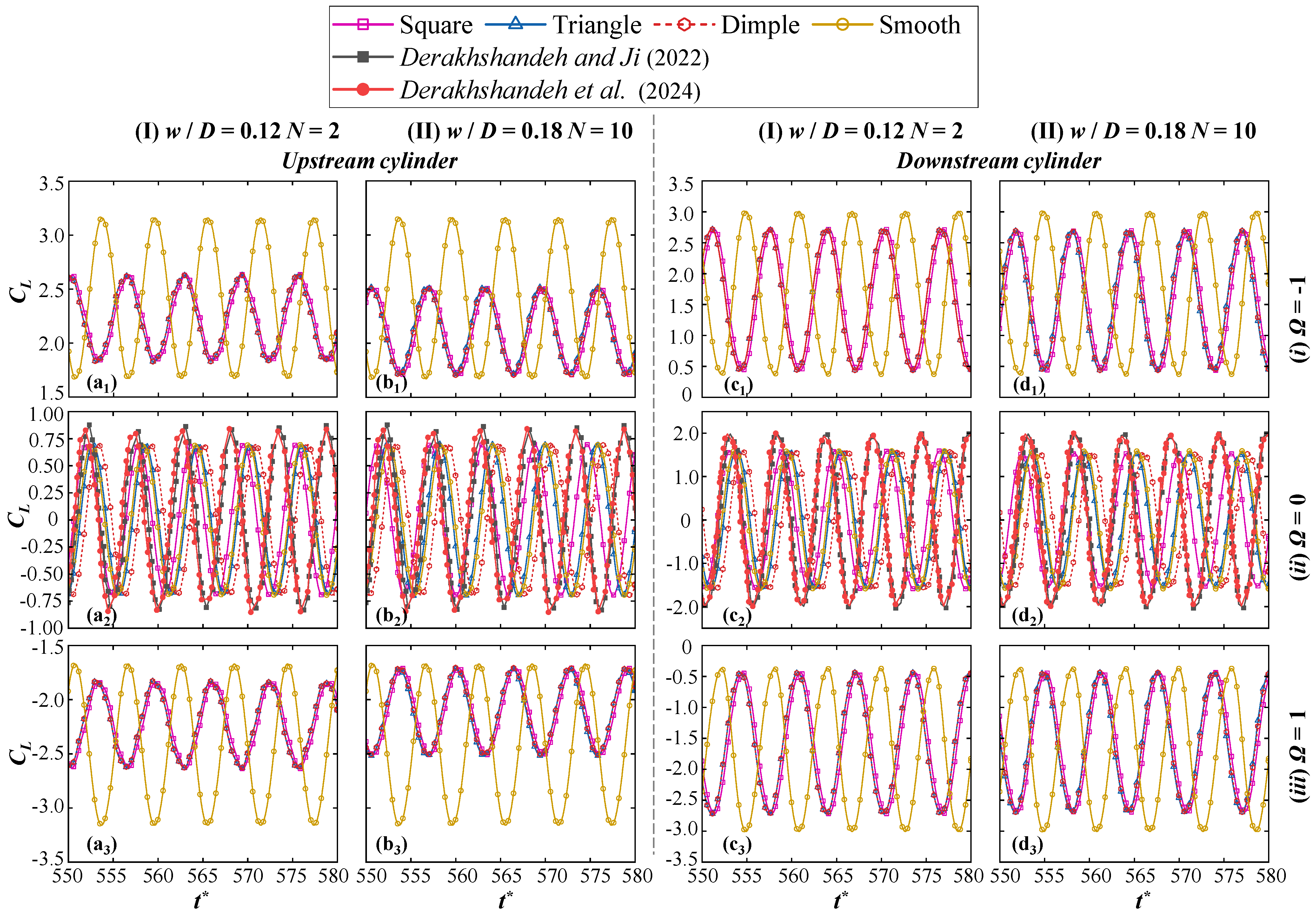
Figure 8 and Figure 9 present the effects of w/D = 0.12 and 0.18, N = 2 and 10, groove type (square, triangle and dimple), and Ω = −1, 0 and 1 on the time histories of drag coefficient (CD) and lift coefficient (CL) under extreme conditions. It should be noted that the analysis of CD and CL is conducted after the flow reaches a stable periodic state. To validate the current research findings, the CL and CD are compared with the results from existing studies [40,41]. Although slight differences in peak values and phase exist, attributed to variations in computational domain and boundary conditions, the overall trends show good agreement. This consistency confirms the reliability of the results and the accuracy of the numerical methodology employed. Figure 8 summarizes the variation of CL over time for both the upstream and downstream cylinders under extreme conditions. All computed cases exhibit a synchronous and in-phase trend under Ω = 0, independent of surface pattern [see Figure 8(a2–d2)]. This indicates that variations in the separation point lead to phase advancement or delay, thereby affecting vortex shedding and lift characteristics.
Additionally, the CL value of the downstream cylinder increases significantly by approximately 58% compared to the upstream cylinder. This increase is attributed to the formation of gap vortices, which accelerate vortex shedding in the wake region of the downstream cylinder. Once rotational speed is applied, the Magnus effect leads to a pressure decrease on the rotating side and a pressure increase on the non-rotating side, thereby increasing CL [see Figure 8(a1–d1)]. Regardless of the low width-to-diameter ratio (w/D = 0.12 and N = 2) or high width-to-diameter ratio (w/D = 0.18 and N = 10) surface patterns, the resulting CL is lower than smooth cylinder. Grooves induce earlier flow separation, which reduces the rear-surface pressure and exacerbates vortex shedding instability, consequently diminishing mean CL (see Figure 7).
Compared to the smooth cylinder, the CL of the upstream cylinder decreases by 17.2% and 20.8% for the different w/D, respectively [see Figure 8(a1,b1)]. Further observations reveal that the surface structure with a higher w/D corresponds to a lower CL than the lower w/D. This suggests that the high w/D grooves on the cylinder further advance the separation point, thereby suppressing the instability of vortex shedding. In contrast to the upstream cylinder, the CL fluctuations of the downstream cylinder under the influence of surface structures are smaller (2.08 ≤ CL ≤ 2.19). This further demonstrates that the grooved structure effectively reduces lift fluctuations at high amplitudes by stabilizing vortex shedding. When Ω = 1, the results are numerically identical to those at Ω = −1 but in the opposite direction.
Additionally, Figure 9 further summarizes the time histories of CD for both upstream and downstream cylinders under extreme conditions. Under Ω = 0, the smooth cylinder and the triangular patterned cylinder exhibit the same phase variation [see Figure 9(a2–b2)], with the CD of the triangular groove reaching a peak, increasing by approximately 0.78%. This reflects that the triangular groove structure has a minimal impact on wake separation when Ω = 0, with the separation point location being close to that of a smooth cylinder. In contrast, under high-amplitude surface patterns, the square groove shows a significant phase-leading effect, while the dimpled groove exhibits a phase-lagging effect. These effects appear to follow an out-of-phase trend (Figure 9(b2) compared to Figure 9(a2)). This indicates that complex surface geometries can alter the phase differences in wake vortex shedding, thereby influencing the fluctuation characteristics of CD. For the downstream cylinder, CD decreases to half of its initial value [see Figure 9(a2,c2)]. As surface pattern amplitude increases, the CD of the smooth cylinder exceeds the other grooves, with an increase of about 8.8%. This is attributed to the grooved structure effectively reducing wake momentum loss and drag when the w/D is large. This phenomenon may be attributed to the rearward shift in the separation point caused by the increased surface amplitude, reducing the pressure differential between the front and rear. Notably, regardless of Ω, the CD curves for the same amplitude surface patterns tend to converge [see Figure 9(a1–d1,a3–d3)]. Therefore, the impact of rotational speed on the drag of grooved cylinders tends to saturate under specific structural conditions. Further analysis reveals that the CD curve profiles for low-amplitude surface patterns differ significantly from those for high-amplitude surface patterns [see Figure 9(a1–b1,a3–b3)].

4.1.3. RMS Lift Coefficient and Time-Averaged Drag Coefficient

Due to changes in the surface geometry of the cylinders, the aerodynamic parameters of the flow field are adjusted accordingly. Figure 10, Figure 11, Figure 12 and Figure 13 present the variations in the root mean square of the lift coefficient ( C L ) and the time-averaged drag coefficient ( C ¯ D ) for both upstream and downstream cylinders, compared with the smooth cylinder. The calculations of C L and C ¯ D are based on data obtained from 10 periods within the steady regime.
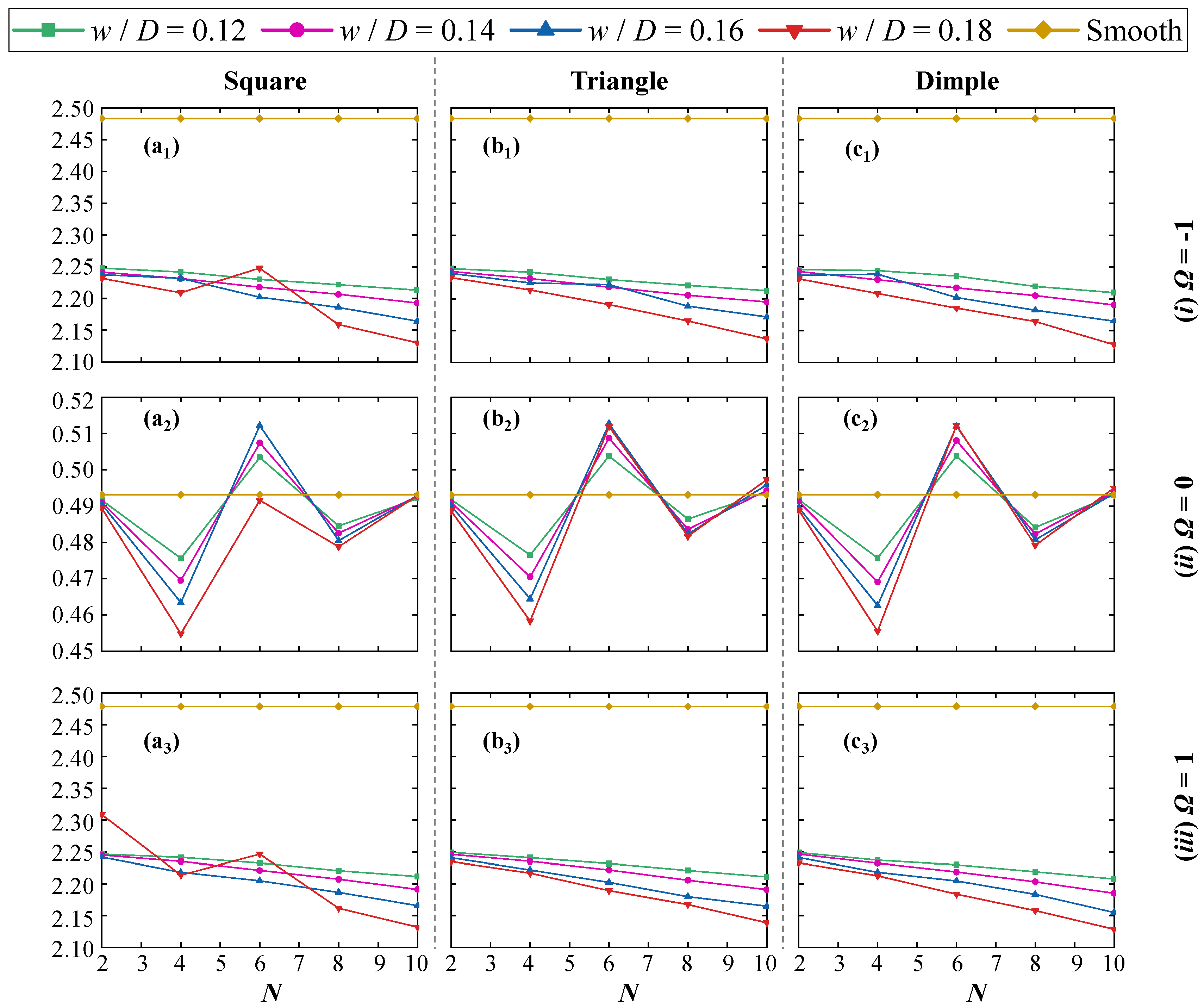
Figure 10 summarizes the C L values of the upstream cylinder under various simulation conditions. The curve profiles for all analyzed cases exhibit an approximate “w” shape and show a consistent trend at Ω = 0 [see Figure 10(a2–c2)]. The peaks and troughs of the “w” shape are either higher or lower than the smooth cylinder. Notably, the square-grooved cylinder with w/D = 0.18 displays relatively distinct characteristics (see Figure 10(a2)). Specifically, at N = 6, its peak is slightly lower than the smooth cylinder, with a reduction of approximately 3.97% compared to the triangular and dimpled grooves. This phenomenon is likely due to reduced lift caused by flow instability under the surface pattern. When the groove type transitions from square to triangle (see Figure 10(b2)), the C L values for all w/D exceed the smooth cylinder as N increases to 10. This indicates that the triangular grooves stabilize the vortex shedding period by altering the location of the flow separation point, thereby increasing the amplitude of lift fluctuations. However, in the case of the dimpled groove (see Figure 10(c2)), the amplitude slightly decreases, with values exceeding the smooth cylinder only for w/D = 0.14 and 0.18. This demonstrates that localized surface depressions can enhance the fluid recirculation region, thereby increasing wake instability.
When Ω = −1, the C L values increase significantly, and all analyzed cases show values lower than the smooth cylinder, exhibiting a trend independent of other parameters [see Figure 10(a1–c1,a3–c3)]. This phenomenon indicates that the presence of the groove structure can effectively suppress part of the lift generated by the Magnus effect. Additionally, C L decreases monotonically with increasing N. However, a notable jump occurs at N = 6, with the amplitude increasing by approximately 2.08% compared to the w/D = 0.16 condition (see Figure 10(a1)). This suggests that the square groove enhances lift more effectively under larger w/D and at N = 6. Under Ω = 1, the C L value for the square groove at N = 2 increases by 3.45% compared to the Ω = −1 (see Figure 10(a3), relative to Figure 10(a1)). Further analysis reveals that within a specific frequency range (4 ≤ N ≤ 6), the triangular and dimpled grooves exhibit opposite trends in influencing lift at w/D = 0.16 [see Figure 10(b1–c1)]. However, this variation fails to occur under Ω = 1 [see Figure 10(b3–c3)].
Figure 11 summarizes the C L for the downstream cylinder. In contrast to the “w”-shaped profiles shown in Figure 10(a2–c2), Figure 11 exhibits an “M”-shaped trend under the same conditions. Additionally, C L values slightly exceed the smooth cylinder only at a specific frequency (N = 4). Notably, the largest fluctuation amplitudes occur for the triangular and dimpled grooves with w/D = 0.18 [see Figure 11(b2–c2)]. It is worth mentioning that at N = 6, the C L exhibit abnormal behavior. The C L value for the square groove approaches the smooth cylinder, with an amplitude approximately 12.9% lower than other groove types. This suggests that, under this configuration, the square groove is ineffective at reducing lift fluctuations; however, the opposite is true when w/D = 0.16. When the square groove is replaced by the triangular groove, the minimum lift is achieved under the same operating conditions (see Figure 11(b2)). Sharp-edged square grooves tend to promote intense vortex shedding, whereas the smoother geometries of triangular and dimpled grooves help stabilize the flow and mitigate flow-field instability.
When the rotational speed increases to −1, the C L values for all cases remain within a narrow range (1.75 ≤ C L ≤ 1.77), significantly lower than the smooth cylinder [see Figure 11(a1–c1)]. However, under counterclockwise rotation at the same speed, the reduction in C L is approximately 6.86% smaller compared to clockwise rotation. This phenomenon is particularly evident under the low surface pattern of the square groove (N = 2) (see Figure 11(a3)). This result indicates that the direction of rotation has a significant impact on the fluctuations of flow forces in the square-grooved cylinder configurations examined in this study.
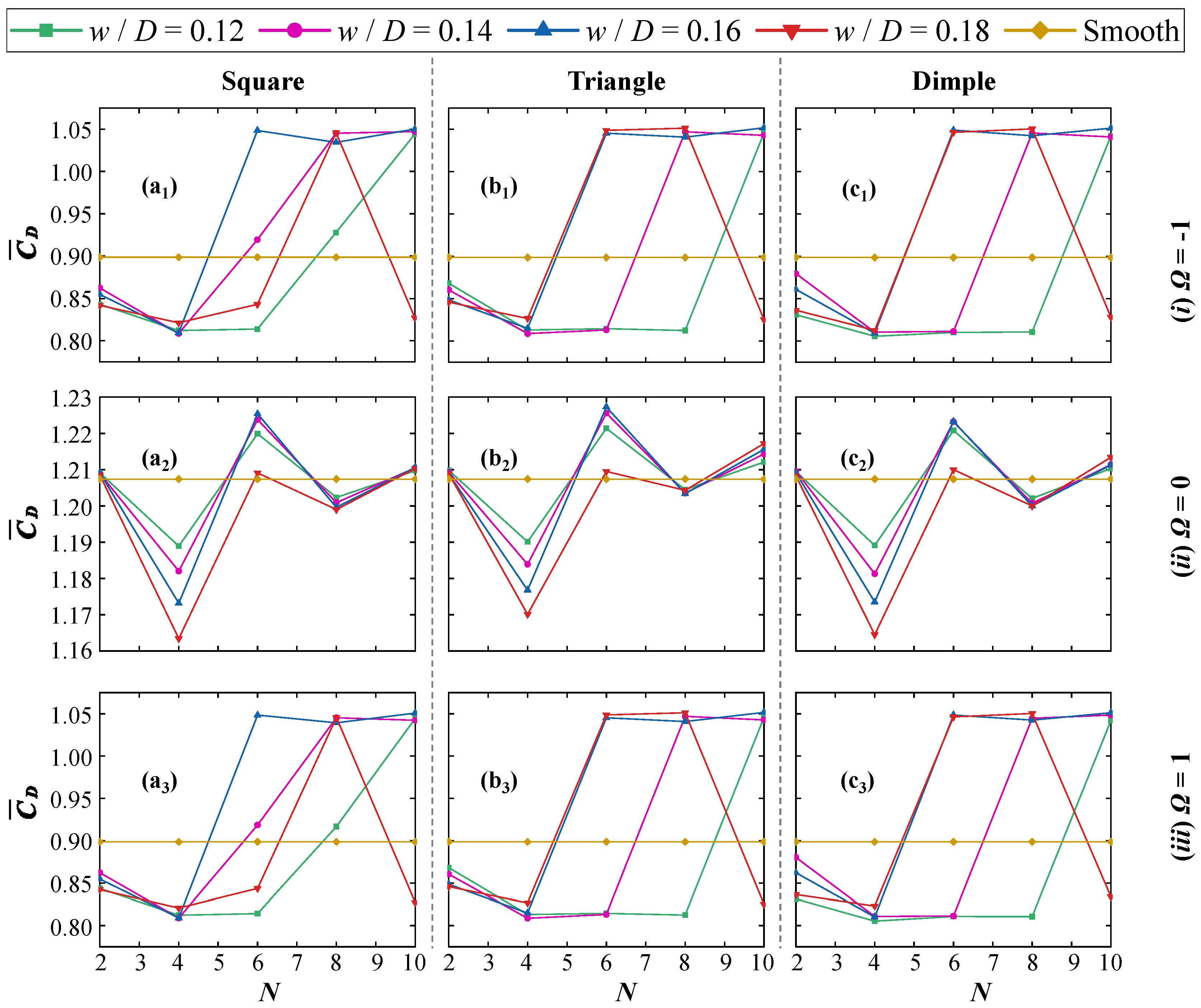
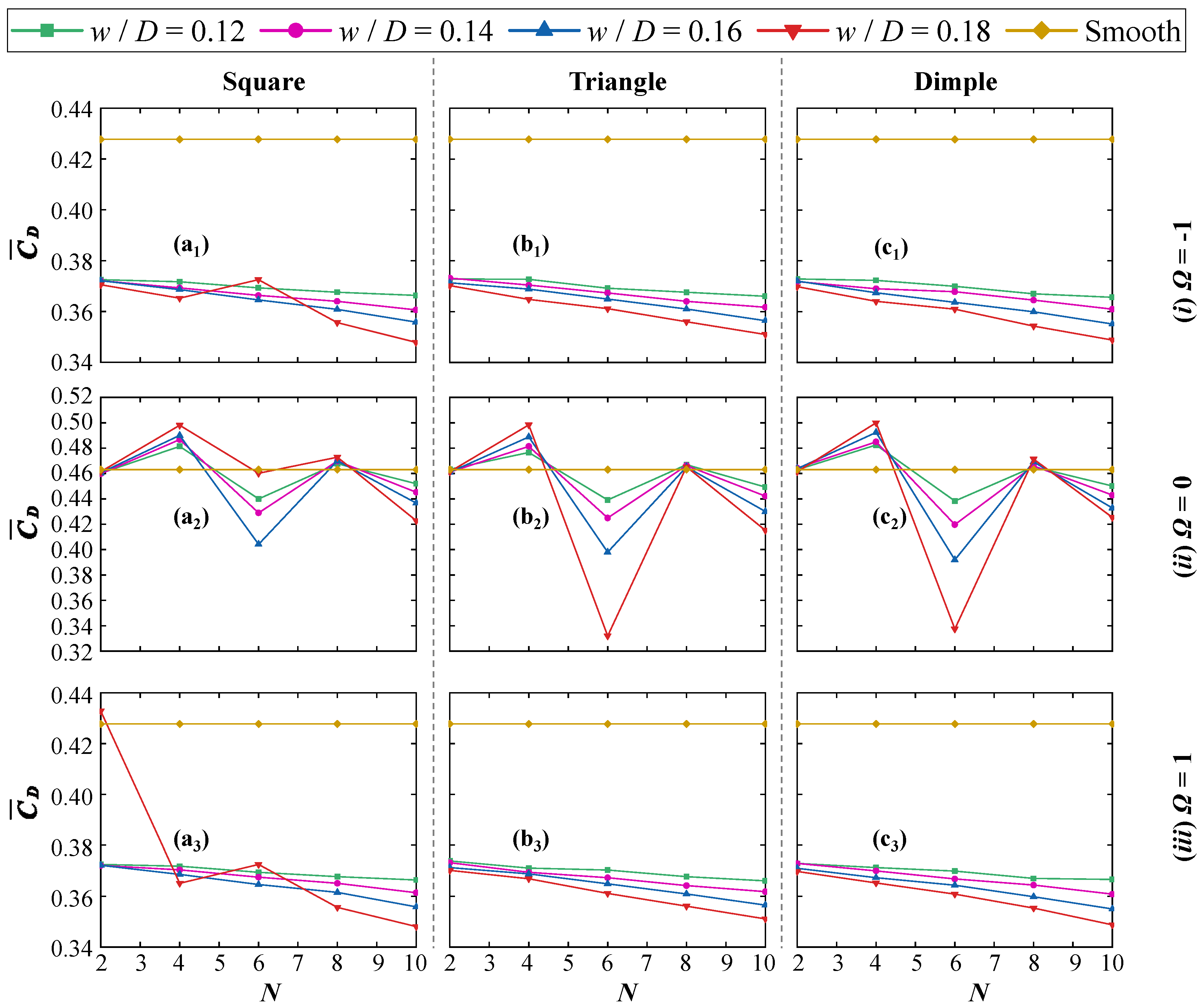
Simultaneously, Figure 12 presents the C ¯ D of the upstream cylinder. The results show a consistent overall trend across all cases in the stationary state [see Figure 12(a2–c2)]. When the w/D exceeds 0.16, the increase in C ¯ D for the triangular groove is relatively moderate and lower than the square and dimpled grooves (N = 4). As the rotational speed increases (Ω = −1), drag fluctuations significantly decrease [see Figure 12(a1–c1,a3–c3)], independent of the groove type.
It is noteworthy that the C ¯ D of the upstream cylinder exhibits a non-monotonic trend with increasing groove number, initially decreasing and then increasing. This behavior may be attributed to changes in near-wall disturbance, inter-groove interactions, and the evolution of vortex structures induced by the increased groove number. In particular, for groove numbers in the range of N = 6 to 10, the dimpled and triangular grooves tend to enhance local recirculation, resulting in elevated drag. Moreover, the introduction of cylinder rotation further intensifies the complex interactions between groove type and groove number. Therefore, this phenomenon reflects a nonlinear response of the underlying physical mechanisms.
As the frequency increases (e.g., w/D = 0.14 and 0.16), the C ¯ D profile for the square groove tends to become more consistent. In contrast, for the other two configurations, although the trend of C ¯ D remains similar, the maximum value is limited to N = 8. Particularly at N = 6, the C ¯ D of the square groove is lower than the smooth cylinder, displaying different behavior compared to other groove types (see Figure 12(a1)). Interestingly, when the N reaches 10, a sharp decline in C ¯ D occurs for the w/D = 0.18, with a reduction of approximately 20.9%. This phenomenon may be attributed to an excessive number of grooves, causing the flow separation point to shift toward the back-pressure region, a behavior independent of the groove type [see Figure 12(a1–c1)]. This indicates that under high-frequency conditions, the drag reduction effect of the grooved structure exhibits significant nonlinear characteristics. Additionally, this observation suggests that operating under lower frequencies (2 ≤ N ≤ 6) and higher frequencies (8 ≤ N ≤ 10) may provide insights for designing configurations that avoid large drag fluctuations.
Additionally, Figure 13 further presents the C ¯ D of the downstream cylinder. Under Ω = 0, all profiles are similar [see Figure 13(a2–c2)], with peaks at N = 4 and troughs at N = 6, exhibiting values higher and lower than those of the smooth cylinder, respectively. When Ω = −1, the C ¯ D reaches its maximum value, approximately 0.373, for the square groove configuration with w/D = 0.18 and N = 6 (see Figure 13(a1)). Under the opposite rotational direction (see Figure 13(a3)), a sudden change is observed at N = 2, where the C ¯ D exceeds the smooth cylinder. This further confirms that the coupling of surface structures and rotational effects significantly regulates the hydrodynamic distribution in the wake. It is noteworthy that at N = 6, the C ¯ D exhibits a similar pattern to the C L shown in Figure 10. Additionally, N = 6 may correspond to a natural frequency of the configuration, thereby triggering specific vortex shedding modes. This response mechanism appears to be more pronounced under the influence of square grooves, likely due to the synergistic effect between groove-induced flow instability and frequency characteristics.
In summary, based on the results from Figure 10, Figure 11, Figure 12 and Figure 13, it is evident that the square groove tends to exhibit significant fluctuations in lift and drag under specific frequencies and different rotational directions. Simultaneously, surface geometry plays a regulatory role in flow field instability. The square grooves, with the deeper concave structures, reduce recirculation in the wake region. Under medium-frequency conditions, triangular grooves delay the separation point, enhancing the stability of lift fluctuations.

4.1.4. Strohal Number

To describe the variation in vortex shedding frequency, Table 4 lists the Strouhal numbers for each case. The results indicate that St values are primarily influenced by rotational speed, while the effects of w/D, N and groove type are negligible. Under Ω = 0, the vortex shedding frequency of the tandem grooved cylinders is similar to smooth cylinders. However, when Ω is within the range of −1 to 1, the vortex shedding frequency in the wake of tandem grooved cylinders is reduced by approximately 7.14% compared to smooth cylinders. This indicates that changes in St are primarily governed by vortex shedding frequency, while the increase in Ω further suppresses frequency fluctuations in the wake region, consistent with the observations in Figure 6. Notably, the St values are 0.172 and 0.153 under Ω = 0 and 1, respectively. The lowest St value of 0.079 is observed for the square-grooved cylinder under clockwise rotation in specific conditions (N = 4, w/D = 0.12). Therefore, the subtle differences in surface patterns have a negligible effect on St under stationary conditions, while the vortex shedding frequency of square grooves decreases significantly at high rotational speeds. This finding provides important insights for further optimizing surface pattern designs to reduce noise and drag energy consumption in the wake region.

4.1.5. Time-Averaged Pressure Coefficient

The relationship between the time-averaged pressure coefficient ( C ¯ p ) and Ω, groove type, w/D and N is shown in Figure 14 and Figure 15. Figure 14 presents the distribution of C ¯ p fluctuations for the upstream cylinder.
It is noteworthy that in most cases, the C ¯ p fluctuation values are higher than the smooth cylinder, especially under Ω = 0, where this phenomenon is more pronounced [see Figure 14(a2–c2)]. Interestingly, when N = 4 (w/D = 0.12), the results are almost identical to the smooth cylinder, regardless of the groove type. A possible explanation is that the increase in the pressure gradient upon fluid entry is insufficient to cause significant deceleration. In addition, the acceleration upon exit fails to alter the flow separation point, resulting in an overall effect that may cancel out. Additionally, within a specific frequency range (N ≤ 6), the fluctuation trends of different groove types are similar, particularly for w/D = 0.12, 0.16 and 0.18 [see Figure 14(a2–c2)]. However, when w/D = 0.14, the fluctuation trend of the square groove differs significantly from the triangular and dimpled grooves. As N increases, the overall fluctuation trend becomes more complex (see Figure 14(a2)). This is especially true when N ≥ 6, where the fluctuation amplitude slightly decreases and falls below the triangular and dimpled grooves [see Figure 14(a2–c2)]. This indicates that the deep concave characteristics of square grooves enhance wake-attached flow and suppress pressure fluctuations, with the effect being more pronounced at smaller w/D ratios.
When w/D decreases to 0.12, the pressure fluctuation amplitude for the triangular and dimpled grooves is minimized, demonstrating the best fluctuation suppression effect. This suggests that under high frequency and a low width-to-diameter ratio (w/D = 0.12 and 0.14), unstable pressure fluctuations are significantly suppressed. As the groove area approaches the critical value (triangle ≤ square ≤ dimple), this suppression becomes more pronounced. Further analysis reveals that when the w/D increases to 0.18, the variation in pressure fluctuations becomes significantly more pronounced, regardless of the groove type. This may be related to the larger recirculation regions within the groove, consistent with the findings in Figure 7. Particularly when N is between 2 and 4, the reduction in pressure fluctuations for the square, triangular, and dimpled grooves is 34.2%, 21.1% and 11.1%, respectively. This indicates that the impact of different grooves on pressure fluctuations significantly depends on their geometries, as they alter wake retention and vortex structures.
As Ω = −1, compared to the stationary condition, the amplitude of pressure fluctuations induced by frequency variation (2 ≤ N ≤ 4) slightly decreases (see Figure 14(a1)). At w/D = 0.16 and 0.18, the fluctuation amplitude tends to decrease, while at w/D = 0.12 and 0.14, the opposite trend is observed. When the N exceeds 4, the pressure fluctuations of most patterned cylinders gradually diminish, falling below the level of the smooth cylinder (see Figure 14(a1)). This change is likely induced by the combined effects of surface patterning and rotation, which delay the separation point, enhance attached flow, and reduce the pressure coefficient. These results suggest that optimizing surface pattern design and adjusting rotational speed can provide an effective strategy for reducing the pressure distribution on cylinder surfaces. When the frequency further increases (8 ≤ N ≤ 10), the pressure fluctuations of the square-grooved cylinder with w/D = 0.18 significantly increase, by approximately 6.4%. This indicates that when N reaches 10, the fluid disturbances caused by the square grooves become too intense. This intensity potentially disrupts the attached flow, leading to more frequent or unstable vortex shedding, which causes the pressure coefficient to rise. In contrast, the triangular-grooved cylinder exhibits more compact and stable pressure fluctuations under various operating conditions (see Figure 14(b1)). A similar phenomenon is observed for the dimpled-grooved cylinder, but at w/D = 0.14 and N = 4, pressure fluctuations peak, with an amplitude 9.61% higher than the smooth cylinder (see Figure 14(c1)). This may be attributed to the structural characteristics of the dimpled groove, which create a larger recirculation zone, leading to a more complex flow structure. Particularly at w/D = 0.14 and N = 4, vortices are more likely to form within the grooves, thereby increasing the pressure coefficient.
When the rotational direction changes, significant changes in pressure fluctuations are observed across most conditions, except for w/D = 0.16, within a specific frequency range (4 ≤ N ≤ 8) (see Figure 14(a1,a3)). A similar phenomenon occurs under the dimpled groove condition (N = 4), where the fluctuation characteristics change notably after the rotational direction is reversed (see Figure 14(a1,a3)). However, the pressure fluctuations of the triangular groove remain stable (see Figure 14(b3)). These results provide valuable insights for the future design of grooved cylinders with different rotational directions, offering important guidance to avoid unfavorable operating conditions.
Under co-rotating conditions, the time-averaged pressure fluctuation curves for the downstream cylinder are also analyzed (see Figure 15). Compared to the upstream cylinder, except for the peaks observed at N = 6 for all groove types, the pressure fluctuation amplitudes are generally lower than or equal to the smooth cylinder in other cases [see Figure 15(a2–c2)]. This indicates that at N = 6, the square groove is more sensitive to low-amplitude surface disturbances compared to the triangular and dimpled grooves. The peak pressure fluctuation for the square groove differs from the triangular and dimpled grooves. It occurs at w/D = 0.14 and w/D = 0.18, respectively, with an increase of 4.71% and a decrease of 15.1% compared to the smooth cylinder. Further analysis reveals that two pairs of curves under different w/D exhibit opposite trends: w/D = 0.14 versus w/D = 0.18, and w/D = 0.12 versus w/D = 0.16 (see Figure 15(a2)). Interestingly, while the triangular and dimpled grooves exhibit similar phenomena, there is a significant difference in the effect of surface pattern size. For the triangular groove, the pressure fluctuation trends for w/D = 0.18 and w/D = 0.16 are consistent, whereas w/D = 0.12 and w/D = 0.14 show opposite trends (see Figure 15(b2)). In contrast, for the dimpled groove, the evolution trends for w/D = 0.14 and w/D = 0.18 are reversed, while w/D = 0.12 and w/D = 0.16 show similar trends (see Figure 15(c2)). This difference is evidently influenced by the distinct characteristics of the groove types.
As Ω = −1, the pressure fluctuation distribution of the downstream cylinder exhibits a trend similar to the upstream cylinder [see Figure 14(a1–c1) and Figure 15(a1–c1)], but with an increase in fluctuation amplitude under different surface pattern sizes. Notably, w/D = 0.14 and w/D = 0.16 display the same developmental trend, while w/D = 0.12 and w/D = 0.18 show opposite trends. Additionally, only in the case of w/D = 0.14 does the fluctuation amplitude fall below the smooth cylinder (see Figure 15(a1)). It is particularly noteworthy that the downstream cylinder with the triangular groove pattern shows a monotonically increasing relationship with N within a specific frequency range (2 ≤ N ≤ 8). More interestingly, as the surface size increases, the starting point of this increasing trend gradually decreases (see Figure 15(b1)). When the pressure fluctuation reaches its maximum value (N = 10), larger surface pattern sizes (w/D = 0.16 and 0.18) and smaller surface pattern sizes (w/D = 0.12 and 0.14) exhibit opposite trends. These trends are consistent with the behavior observed in the upstream cylinder (see Figure 14(b1)). The pressure fluctuation evolution of the dimpled groove follows a similar pattern to the triangular groove (see Figure 15(c1)). Although smaller surface pattern sizes (w/D = 0.12 and 0.14) exhibit similar trends, there are still differences, especially at N = 4, where the deviation reaches its maximum value, approximately 0.303. It is worth noting that when the rotational direction is reversed, the pressure fluctuation distribution of the downstream cylinder is similar to the upstream cylinder.

4.2. Heat Transfer

4.2.1. Isotherms

The thermal behavior around the tandem cylinders is analyzed through the distribution of isotherms. The isotherms are non-dimensionalized using the expression Θ * = (TT)/(TwT), and are presented for the extreme values of the design parameters (w/D = 0.12 and 0.18; N = 2 and 10; square, triangle and dimple; Ω = −1, 0 and 1). The isotherm distribution around the stationary patterned cylinders is analyzed first, followed by a discussion on the rotating patterned cylinders. The isotherm levels in all figures are kept consistent to allow for direct comparison of the results.
The isotherms around the non-rotating patterned cylinders are shown in Figure 16I(a2c2),II(a2c2), corresponding to w/D = 0.12 and 0.18, and N = 2 and 10, respectively. For the stationary patterned cylinders, the isotherms are densely concentrated on the front side of the cylinder, indicating a large temperature gradient in the frontal region. In contrast, heat transfer in the wake region is primarily dominated by diffusion, resulting in a relatively uniform distribution. Under stationary conditions, the groove type and frequency influence the thermal field only indirectly through the flow field. Therefore, the isotherm distribution exhibits no significant variation with increasing w/D and N. When rotational speed is applied, the thermal gradient distribution around the rotating cylinders with Ω = −1 and 1 exhibits symmetry relative to Ω = 0 [see Figure 16I(a1c1,a3c3)]. This causes the isotherms to lose central symmetry and shift in the direction of the cylinder’s rotation. Notably, under high-amplitude surface patterns, this distribution shows significant differences on the surface of the downstream cylinder [see Figure 16II(a1b1,a3b3)]. In summary, at Ω = 0, the surface pattern and groove type have minimal impact on the thermal gradient distribution, while rotational speed has a more significant effect on heat transfer.

4.2.2. Comparison of Average Nusselt Number for Patterned Tandem Cylinders

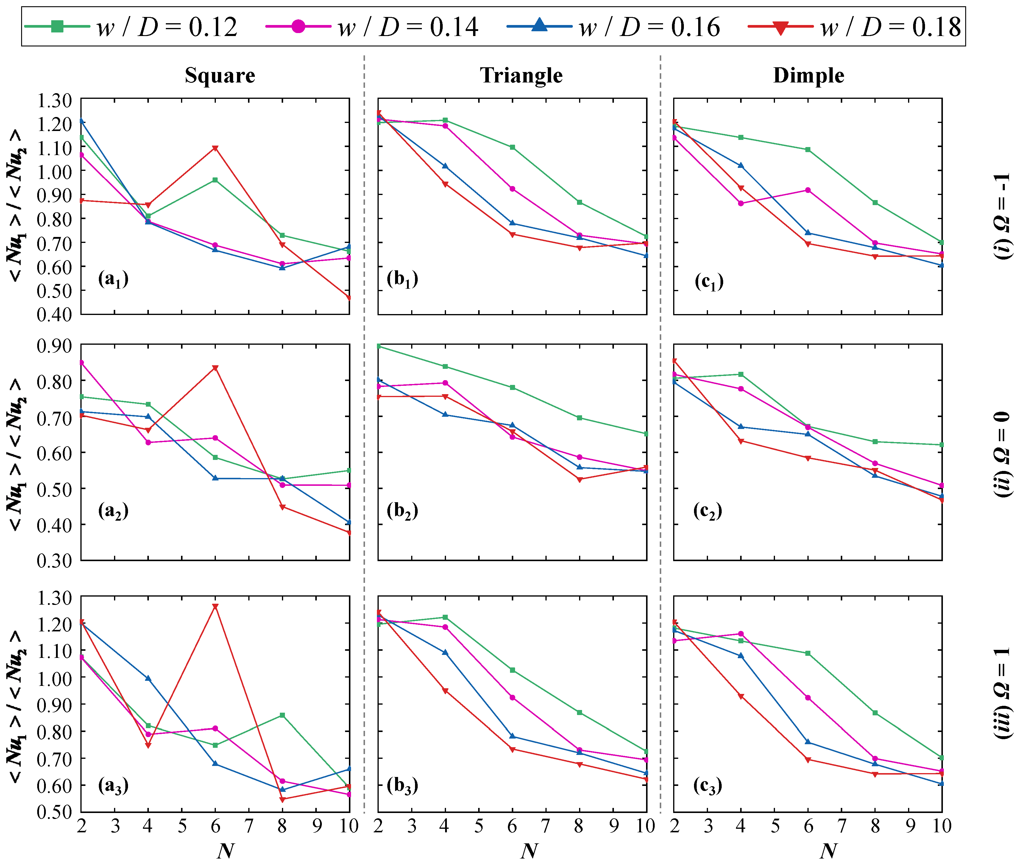
To thoroughly analyze the heat transfer characteristics between the upstream and downstream cylinders, a systematic comparison of the average Nusselt number for tandem grooved cylinders is conducted based on N, groove type, w/D and Ω (see Figure 17). Subscripts 1 and 2 represent the upstream and downstream cylinders, respectively.
The results indicate that, regardless of stationary and rotating conditions, the average Nusselt number generally decreases as the N increases across different surface pattern configurations. This suggests that the downstream cylinder absorbs more heat compared to the upstream cylinder. Further analysis reveals that under specific conditions (w/D = 0.18 and N = 6), the heat transfer performance of the square groove changes significantly. The Nusselt number increases by approximately 42.7% compared to the case of w/D = 0.12 (see Figure 17(a2)). This indicates that, within a certain frequency range (4 < N < 8), the vortex structures in the wake region undergo significant changes. Simultaneously, high w/D grooves enhance vortex mixing, improving convective heat transfer efficiency downstream of the cylinder. Similar phenomena are observed in smaller w/D s as well. Although the triangular groove and the dimpled groove do not exhibit similar changes (see Figure 17(b2,c2)), both configurations demonstrate higher overall thermal efficiency. Notably, under w/D = 0.12, the heat transfer curve of the triangular groove consistently exceeds other cases (see Figure 17(b2)). This indicates that the geometric characteristics of triangular grooves delay the separation point, enhancing the convective heat transfer performance of the upstream cylinder.
As Ω = −1, the square groove exhibits a similar evolution trend under the conditions of w/D = 0.14 and w/D = 0.16. However, at extreme width-to-diameter ratios (w/D = 0.12 and 0.18), a sudden change occurs at N = 6, displaying a consistent developmental pattern (see Figure 17(a1)). This indicates that the steep geometry of square grooves suppresses flow transitions, enhancing the mixing effect of high-frequency vortex shedding on convective heat transfer. In contrast to the square groove, the Nusselt number for the triangular and dimpled grooves shows a monotonically decreasing trend with increasing frequency (see Figure 17(b1,c1)). This demonstrates that both patterns optimize the wake separation point, suppress convective heat transfer fluctuations, and enhance heat transfer stability. Notably, a slight variation is observed for the dimpled groove at w/D = 0.14 and N = 6, although its value remains consistent with the triangular groove. Under counterclockwise rotation, the heat transfer behavior of the square groove becomes more complex, attributed to the steep structure of the groove, which suppresses flow transitions (see Figure 17(a3)).

4.2.3. Thermal Performance Indicators

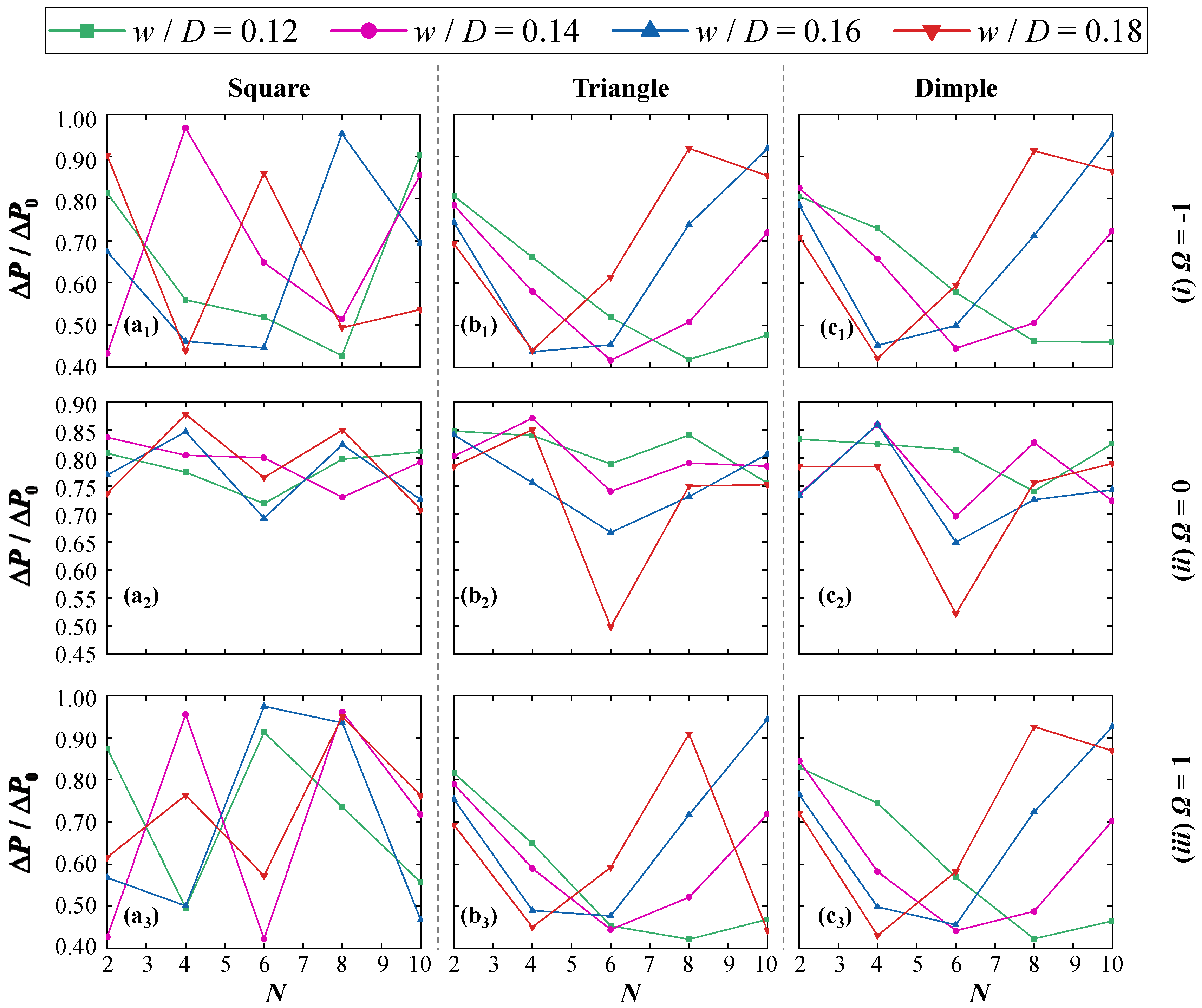
Based on the drag of the grooved surface and the impact on the flow field under rotation, this section first examines the relationship between the pressure drop (ΔPP0) of tandem cylinders and the selected variables (see Figure 18). Here, Nu0 and P0 are obtained from the numerical simulations of tandem smooth cylinders. The results indicate that, compared to other groove types, the pressure drop loss for square grooves is concentrated in the higher range (0.70 ≤ ΔPP0 ≤ 0.90) (see Figure 18(a2)). This phenomenon is due to square grooves influencing boundary layer separation, forming strong vortices and increasing wall resistance. This suggests that square grooves are at a disadvantage in terms of drag reduction performance. In contrast, the drag reduction effect for triangular and dimpled grooves significantly improves with increasing w/D (see Figure 18(b2,c2)). This effect is particularly pronounced at a specific frequency (N = 6), where the pressure drop for triangular and dimpled grooves decreases by approximately 34.8% and 31.7%, respectively, compared to square grooves.
Notably, as frequency increases, the pressure drop trends for triangular and dimpled grooves are similar and independent of rotational direction (see Figure 18(b1,b3,c1 and c3)). This indicates that both groove types, under rotational conditions, maintain a steady pressure drop variation trend by delaying flow separation. Additionally, smaller w/D correspond to more pronounced drag reduction effects at higher frequencies. Similarly, the square groove also exhibits this characteristic at w/D = 0.12. However, when w/D > 0.12, the square groove shows pressure drop peaks under different w/D and N. This indicates that Ω has a significant impact on drag variation for square grooves at specific frequencies, while other groove types exhibit greater stability (see Figure 18(b1,b3,c1 and c3)).
The overall thermal performance of rotating tandem grooved structures is of great significance in revealing the interaction between thermal behavior and fluid dynamics. The subscript “12” represents the net values for tandem cylinders, while “0” is based on the numerical simulation results of tandem smooth cylinders. Therefore, the Nusselt number ratio between tandem grooved cylinders and tandem smooth cylinders is further analyzed (see Figure 19). As Ω = 0 [see Figure 19(a2–c2)], regardless of w/D, the Nusselt number for triangular and dimpled grooves decreases monotonically with N, and the square groove exhibits a similar trend. Notably, when w/D > 0.12, the heat transfer performance of the triangular groove at N = 2 surpasses the smooth cylinder. This indicates that as the groove shape approaches a smooth surface, the enhancement in heat transfer becomes more significant. In contrast, the heat transfer performance of the square groove peaks at N = 6, exceeding other cases with w/D = 0.18 under the same conditions, with a value of approximately 0.943. This indicates that square grooves enhance vortex mixing in the wake, improving local heat transfer; however, the high wall friction adversely affects overall efficiency. As the N increases to its maximum, the heat transfer improvement for triangular and dimpled grooves compared to the square groove is 7.74% and 3.35%, respectively. Under rotating conditions [see Figure 19(a1–c1)], the heat transfer range for all groove types decreases due to the earlier flow separation. This phenomenon is particularly pronounced in the square groove (see Figure 19(a1)). This indicates that the steep geometry of square grooves under rotational conditions exacerbates flow instability, further diminishing heat transfer performance. In contrast, the heat transfer performance of the triangular and dimpled grooves remains relatively stable with changes in frequency. Meanwhile, the square groove continues to show a significant downward trend, unaffected by Ω. Therefore, under specific conditions, the triangular groove may be a reliable choice for achieving stable heat transfer performance. Notably, under reverse rotation, the abrupt changes in the square groove are suppressed, while other groove types fail to exhibit significant changes (see Figure 19(b3,c3)).
The Thermal Performance Index, calculated from the Nusselt number and pressure drop (see Figure 20), provides a more intuitive way to analyze the heat transfer performance of tandem grooved configurations.
The results indicate that the heat transfer performance of the square groove shows opposite trends at w/D = 0.12 and 0.14; however, as w/D increases, this difference gradually decreases and converges to a slightly declining trend (see Figure 20(a2)). Unlike the square groove, the triangular and dimpled grooves exhibit more stable trends with increasing frequency, and the effect of w/D on the configurations is minimal [see Figure 20(b2c2)]. This suggests that under specific conditions, both the triangular and dimpled grooves contribute positively to heat transfer and drag reduction. Notably, at N = 6 and w/D = 0.18, the TPI of the triangular and dimpled grooves is 33.8% and 28.4% higher than the square groove, respectively. This indicates that at N = 6 and w/D = 0.18, both groove types exhibit superior overall thermal performance compared to square grooves, owing to the efficient drag reduction and stable convective heat transfer mechanisms. As Ω increases [see Figure 20(a1–c1)], the triangular and dimpled grooves follow a consistent trend. The triangular groove demonstrates the best heat transfer performance among all configurations. Specifically, at lower w/D, the system exhibits superior heat transfer performance at high N (see Figure 20(b1)). This indicates that the combination of surface pattern design and frequency optimization can significantly enhance system thermal performance under multiple operating conditions. Similarly, within the frequency range of 6 ≤ N ≤ 8, the square groove shows better heat transfer performance at lower width-to-diameter ratios (w/D = 0.12 and 0.14) compared to higher ratios (w/D = 0.16 and 0.18) (see Figure 20(a1)). However, at w/D = 0.16, the optimal range narrows to 4 ≤ N ≤ 6. This indicates that, regardless of groove type, high N at low w/D and low N at high w/D both enhance heat transfer performance. When reverse rotation is applied, the heat transfer trends of the triangular and dimpled grooves show no significant differences from clockwise rotation, except for the square groove [see Figure 20(a3–c3)].

4.2.4. Analysis of Nusselt Number Distribution Characteristics on the Cylinder Surface

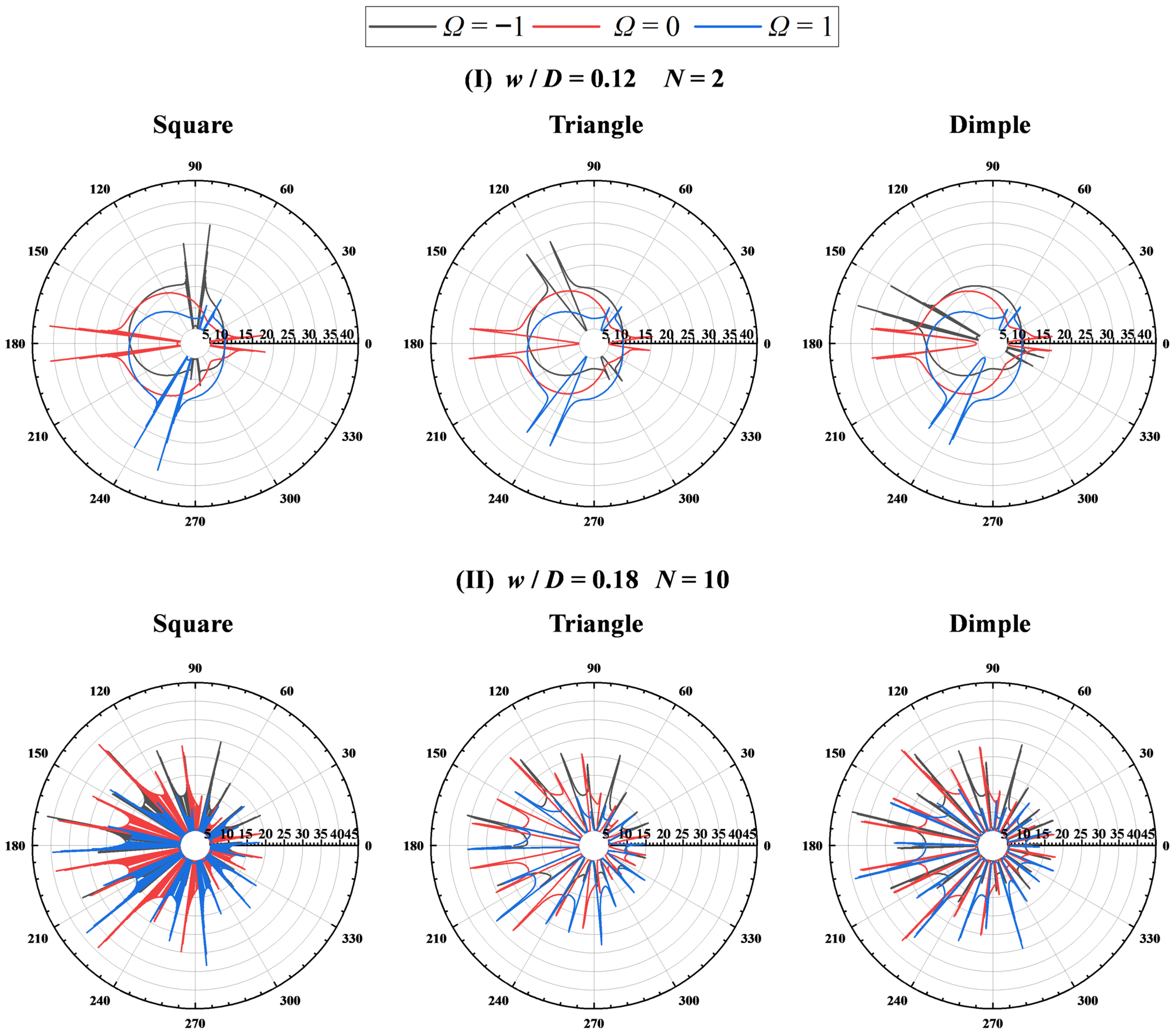
To further investigate the distribution characteristics of the Nusselt number, this study first presents the surface Nusselt number distribution along the polar angle of the grooved cylinder under extreme operating conditions (see Figure 21). All displayed surface Nusselt numbers are obtained under extreme operating conditions.
Under low surface pattern conditions (w/D = 0.12 and N = 2), the Nusselt number gradient distribution at Ω = −1 and Ω = 1 is symmetric about Ω = 0 and independent of the groove type (see Figure 21I). This phenomenon can be attributed to the enhanced turbulence of the fluid around the cylinder’s side due to rotation. The turbulence promotes thermal mixing, which is consistent with the temperature distribution shown in Figure 16I. However, when the surface pattern is increased to w/D = 0.18 and N = 10, a significant change in the Nusselt number distribution is observed at the separation points of different groove angles (see Figure 21II). This distribution pattern suggests a potential regime, which can be explained by the effect of groove geometry on flow separation and vortex strengthening. At a certain scale ratio, the vortex effect induced by larger grooves is more pronounced, enhancing heat transfer and resulting in higher Nusselt numbers. In particular, the dimple grooves, due to the larger curvature, exhibit the strongest vortex effects and display the highest Nusselt numbers.
The Nusselt number around the downstream cylinder shows mild fluctuations localized near the wall, with an overall smooth distribution. Figure 22 highlights the spatial influence of wake disturbances on local heat transfer, rather than large-scale variations in intensity.
Further analysis of the graphs reveals a clear shift in the Nusselt number of the downstream cylinder towards both the upper and lower sides, likely caused by the Magnus effect [see Figure 22I(a1–c1,a3–c3))]. In contrast, the stationary downstream cylinder also exhibits a similar trend, but with more pronounced Nusselt number values [see Figure 22I(a2–c2)], especially in the cases of square and concave groove shapes.
Figure 21 shows that different groove profiles affect the heat exchange with the surrounding fluid, thereby influencing the wall heat transfer distribution on the downstream cylinder. Although these local disturbances do not exhibit strong quantitative characteristics, they still carry physical significance in terms of spatial distribution and structural patterns.
As the surface pattern increases to its maximum value, the heat exchange performance on the front and side surfaces of the downstream cylinder improves (see Figure 22II). Therefore, the contour visualization in Figure 22 better reveals the distribution and location of local disturbances, aiding in understanding the overall impact of wake interference on downstream heat transfer.

5. The Relationship Between the Average Nusselt Number, the Number of Grooves, Groove Area and Rotational Speed

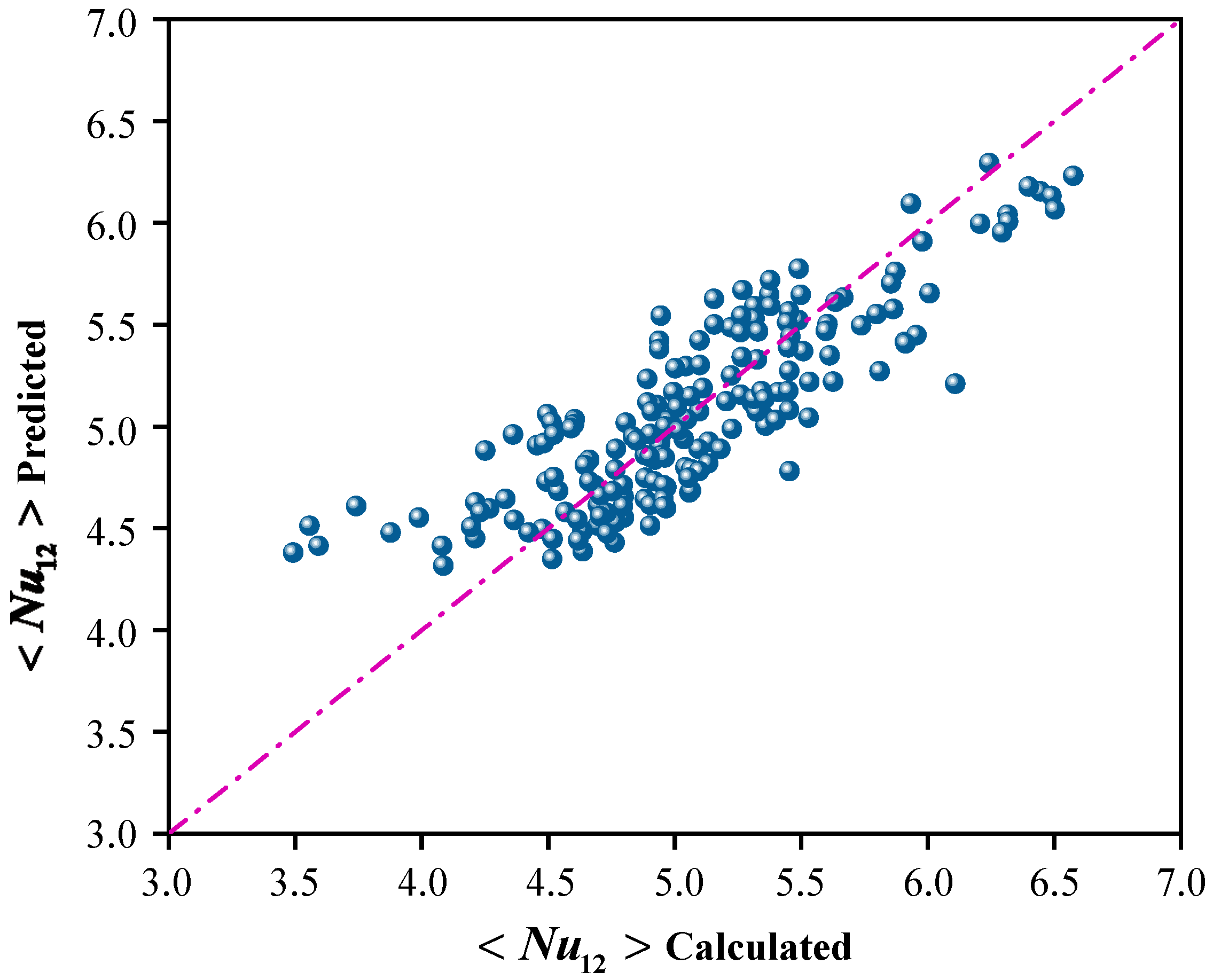
To validate the overall effectiveness of the developed extended model, this paper develops a simplified correlation to expand its applicability to intermediate values of various groove types, w/D, Ω, and N. This correlation provides a theoretical foundation for the design of a wide range of industrial equipment. According to the studies of Panda and Chhabra [81], and inspired by the insights from reference [62], this paper proposes a correlation formula. The formula determines the average Nusselt number (< Nu1,2 >) as a function of Aeq, Ω and N. The term Aeq incorporates the geometric type and corresponding dimensions of the grooves to simplify the calculation process. This parameter is calculated using the area formulas of different groove cross-sections (square, triangular, and dimpled) for a unit spanwise length (D), encapsulating both shape and size effects. The dimpled groove is considered a segment of an elliptical arc. The range of relevant parameters is presented in Table 5. The Nusselt number correlation achieves the best fit through the following equation:
< N u 1 , 2 > = 7.083 ( A e q 0.01 2 ) 0.0323 ( Ω 0.013 ) 0.02 N 0.128
Based on the consideration of all 180 data points, the established correlation demonstrates a minimum deviation of 0.07% and a maximum deviation of 26.89%. Figure 23 illustrates the strong agreement between the numerically calculated Nusselt numbers and the results predicted by the correlation [Equation (20)]. Although the Reynolds number (Re = 200) and Prandtl number (Pr = 0.71) are held constant in this study, Equation (20) still reflects the theoretical dependence of the Nusselt number on these dimensionless parameters. The Re characterizes flow inertia, while the Pr describes the ratio of momentum to thermal diffusivity. Their influence on Nu is captured by the exponents in the equation, consistent with previous studies and supported by established theory. It is worth noting that all data points were uniformly predicted by the same model (20), and identical symbols are used in Figure 23 to reflect the model’s overall fitting capability across the entire parameter space. Figure 23 is intended to emphasize predictive accuracy and global applicability, rather than to facilitate a comparative classification of different grooves geometries.

6. Conclusions

This study conducts a numerical investigation of fluid flow around rotating tandem cylinders with surface patterns. The research focuses on the effects of surface pattern characteristics (w/D = 0.12–0.18 and N = 2–10), rotational direction (|Ω| ≤ 1) and groove types (square, triangle and dimple) on engineering parameters such as force coefficients, temperature fields and Nusselt numbers. The following key findings are summarized:
The findings indicate that square grooves, characterized by reduced trailing vortex cores, effectively mitigate wake instability at elevated w/D values and substantially improve flow stability under specific conditions. Progressive increases in w/D and N enlarge the crest recirculation zone, elucidating intricate crest–trough interactions; at Ω = 1, groove edge effects additionally trigger upstream separation vortices. In summary, square grooves exhibit pronounced capability in optimizing wake topology and promoting aerodynamic stability.
Square and dimple grooves can markedly regulate the temporal characteristics of lift and drag, underscoring the critical role of surface geometry in fluid mechanics. This modulation effect is particularly prominent in downstream cylinders, where gap vortices contribute to enhanced lift. In contrast, groove structures reduce drag and suppress force fluctuations by altering separation points and wake characteristics. Notably, the magnitude and nature of this effect exhibit nonlinear dependence on geometric parameters and rotational conditions. This observation indicates the potential applicability of groove designs in flow control and in optimizing fluid–structure interaction performance.
In addition, square grooves exhibit relatively high pressure drops. By contrast, triangular and dimple grooves show markedly lower values under identical conditions and maintain stability across varying frequencies, highlighting its good applicability. Regarding pressure fluctuations, dimple grooves show higher amplitudes than smooth cylinders under specific parameter settings. Square grooves provide stronger suppression at smaller width-to-diameter ratios (w/D = 0.12 and 0.14), while triangular grooves sustain wake stability at larger ratios (w/D = 0.16 and 0.18).
With increasing N, the influence of surface morphology on the thermal gradient becomes less pronounced. Triangular grooves maintain comparatively high heat transfer efficiency over a broader range of parameters. Under medium-to-high w/D (≥0.16) and N = 6 conditions, the Nusselt number of square grooves can be approximately 43% higher than that observed at low w/D (0.12). This enhancement is accompanied by pronounced vortex-induced heat transfer effects. However, in terms of the overall TPI, triangular and dimple grooves are superior: at w/D = 0.18 and N = 6, they outperform square grooves by about 34% and 28%, respectively. Correlation formulae have been validated to establish the quantitative relationship between the average Nusselt number and groove area, rotational speed, and frequency. These formulae provide a useful reference for engineering design and for predicting heat transfer performance across different configurations.
In summary, this study reveals the scalability characteristics of flow and heat transfer behavior in grooved dual-cylinder systems. When the groove width ratio w/D ≥ 0.16 and the number of grooves N is around 6, various groove types generally exhibit a synergistic trend of enhanced heat transfer and improved flow stability. This pattern remains consistent across different groove geometries, demonstrating strong generality. This result is not only of significant theoretical importance but also provides valuable reference for engineering practice. For example, in shell-and-tube or tubular heat exchangers, the tube bundle region is often affected by wake vortices, leading to flow instability and insufficient heat transfer. This study reveals that different groove types can regulate vortex structures and heat transfer distribution. Such regulation can be applied to optimize the surface morphology of tandem cylinder bundles, thereby increasing local Nusselt numbers and reducing drag. In large water storage devices, flow stratification and non-uniform circulation velocities can affect the overall temperature distribution; the proposed approach helps mitigate temperature non-uniformities caused by vortex-induced mixing. In electronic cooling systems (such as air-cooled heat sinks), structural modifications of tandem cylinder fins can enhance cooling flow disturbances while maintaining a low pressure drop. This leads to reduced temperature gradients across the chip area and more uniform heat dissipation. Based on these findings, the proposed design principles and parameter optimization strategies can be extended to other grooved structures. This approach is also applicable to engineering systems operating under low-to-moderate Reynolds numbers, such as microchannel coolers and thermal management of electronic devices.
Although this study provides valuable insights, it has several limitations. First, the research is based solely on two-dimensional simulations, and future work could extend to three-dimensional models to further validate the generalizability of the results. Second, the study focuses on a single physical field, and future research could explore the coupling of fluid flow with other physical fields to further enhance the performance of thermal management systems. Additionally, this study did not include experimental validation, and future research could incorporate experimental data to verify the accuracy of the numerical simulations.

Author Contributions

Conceptualization, Y.L. and F.S.; methodology, Y.L. and C.W.; validation, J.X.; formal analysis, C.W.; investigation, F.S. and J.X.; resources, Y.L.; writing—original draft preparation, C.W.; writing—review and editing, Y.L., F.S. and J.X.; visualization, C.W.; funding acquisition, J.L. All authors have read and agreed to the published version of the manuscript.

Funding

This work is supported in part by the Natural Science Foundation Project of Zhejiang Province of China (LY24E090002), the Natural Science Foundation of Ningbo Municipality, China (2022J135) and the Science and Technology Innovation 2025 Major Project of Ningbo, China (2021Z045).

Data Availability Statement

Data will be made available upon request.

Conflicts of Interest

Author Changfa Wang was employed by Yungongfang Intelligent Technology Co., Ltd., No. 9 Chenghai Road, Meishan Free Trade Port Zone, Ningbo 315211, China. The remaining authors declare that the research was conducted in the absence of any commercial or financial relationships that could be construed as a potential conflict of interest.

Nomenclature

L Center-to-center distance between the cylindersαAngular velocity
C L Lift coefficientSuperscripts
C D Drag coefficient*Normalized
D Diameter of the cylinder-Time average
f v Vortex shedding frequency< >Surface average
U Freestream velocityRoot mean square
u Streamwise velocitySubscripts
v Cross-stream velocity w Wall
R e Reynolds number Freestream
S t Strouhal number0Baseline
P r Prandtl numberx,y,zCartesian coordinate system direction
N u Nusselt number12Tandem cylinder
h β Local convective heat transfer coefficient1Upstream cylinder
K Thermal conductivity2Downstream cylinder
T TemperaturemaxMaximum
p Static pressureminMinimum
t TimeAbbreviations
Δ t Time stepCFLCourant-Friedrichs-Lewy number
F ForceSIMPLESemi-Implicit Method for Pressure-Linked Equations
c p Specific heat capacityCGCoarse Grid
ω VorticityMGModerate Grid
C p Pressure coefficientFGFine Grid
Greek alphabet TPIThermal Performance Index
μ Dynamic viscositySMMSliding Mesh Method
ρ Fluid density
β Polar angle

References

  1. Schmidt, H.J.; Woszidlo, R.; Nayeri, C.N.; Paschereit, C.O. Drag reduction on a rectangular bluff body with base flaps and fluidic oscillators. Exp. Fluids 2015, 56, 151. [Google Scholar] [CrossRef]
  2. Patel, C.G.; Sarkar, S.; Saha, S.K. Mixed convective vertically upward flow past side-by-side square cylinders at incidence. Int. J. Heat Mass Transf. 2018, 127, 927–947. [Google Scholar] [CrossRef]
  3. Dhiman, A.; Ghosh, R. Computer simulation of momentum and heat transfer across an expanded trapezoidal bluff body. Int. J. Heat Mass Transf. 2013, 59, 338–352. [Google Scholar] [CrossRef]
  4. Derakhshandeh, J.F.; Gharib, N. Numerical studies of laminar flow over two tandem elliptical cylinders using Ramanujan approximation. J. Braz. Soc. Mech. Sci. Eng. 2021, 43, 169. [Google Scholar] [CrossRef]
  5. El-Maghlany, W.M.; Alnakeeb, M.A.; Teamah, M.A.; Sorour, M.M. Experimental and numerical study of laminar mixed convection from a horizontal isothermal elliptic cylinder. Int. J. Therm. Sci. 2018, 130, 116–127. [Google Scholar] [CrossRef]
  6. Liao, C.C.; Lin, C.A. Influences of a confined elliptic cylinder at different aspect ratios and inclinations on the laminar natural and mixed convection flows. Int. J. Heat Mass Transf. 2012, 55, 6638–6650. [Google Scholar] [CrossRef]
  7. Yoon, H.S.; Nam, S.H.; Kim, M.I. Effect of the geometric features of the harbor seal vibrissa based biomimetic cylinder on the forced convection heat transfer. Int. J. Heat Mass Transf. 2020, 159, 120086. [Google Scholar] [CrossRef]
  8. Cattafesta, L.N.; Sheplak, M. Actuators for active flow control. Annu. Rev. Fluid Mech. 2011, 43, 247–272. [Google Scholar] [CrossRef]
  9. Riahi, H.; Aminossadati, S.M.; Leonardi, C. A discrete immersed boundary method for the numerical simulation of heat transfer in compressible flows. Eur. J. Mech.-B/Fluids 2025, 111, 61–71. [Google Scholar] [CrossRef]
  10. Wang, N.; Aminossadati, S.M.; Leonardi, C. Numerical study of vortex-induced motion and heat transfer characteristics of elliptic cylinders with different aspect ratios. Eur. J. Mech.-B/Fluids 2025, 114, 204328. [Google Scholar] [CrossRef]
  11. Sadeghi, S.; Aminossadati, S.M.; Leonardi, C. Numerical investigation of the role of human motion in the spread of virus-laden droplets from coughing using CFD dynamic mesh technique. Eur. J. Mech.-B/Fluids 2025, 111, 42–60. [Google Scholar] [CrossRef]
  12. Ji, H.; Liu, Z.; Zhao, J.; Wang, B. Enhanced cooling performance in cutting tools using TPMS-integrated toolholders: A CFD-based thermal-fluidic study. Modelling 2025, 6, 73. [Google Scholar] [CrossRef]
  13. Lin, P.; Yuan, X.; Liu, T. Statistical evaluation of API P–Y curve model for offshore piles in cohesionless soils. Modelling 2025, 6, 91. [Google Scholar] [CrossRef]
  14. Nikfarjam, F.; Sohankar, A. Power-law fluids flow and heat transfer over two tandem square cylinders: Effects of Reynolds number and power-law index. Acta Mech. 2013, 224, 1115–1132. [Google Scholar] [CrossRef]
  15. Nikfarjam, F.; Sohankar, A. Study of hysteresis associated with power-law fluids past square prisms arranged in tandem. Ocean Eng. 2015, 104, 698–813. [Google Scholar] [CrossRef]
  16. Liu, M.M.; Lu, L.; Teng, B.; Zhao, M.; Tang, G.Q. Re-examination of laminar flow over twin circular cylinders in tandem arrangement. Fluid Dyn. Res. 2014, 46, 025501. [Google Scholar] [CrossRef]
  17. Alam, M.M. Lift forces induced by phase lag between the vortex sheddings from two tandem bluff bodies. J. Fluids Struct. 2016, 65, 217–237. [Google Scholar] [CrossRef]
  18. Wang, L.J.; Alam, M.M.; Zhou, Y. Two tandem cylinders of different diameters in cross-flow: Effect of an upstream cylinder on wake dynamics. J. Fluid Mech. 2018, 836, 5–42. [Google Scholar] [CrossRef]
  19. Canpolat, C. Characteristics of flow past a circular cylinder with a rectangular groove. Flow Meas. Instrum. 2015, 45, 233–246. [Google Scholar] [CrossRef]
  20. Derakhshandeh, J.F.; Alam, M.M. A numerical study of heat transfer enhancement by a rectangular cylinder placed parallel to the heated wall. J. Heat Transf. 2019, 141, 091702. [Google Scholar] [CrossRef]
  21. El-Makdah, A.M.; Ghanem, F.O. The flow past a cactus-inspired grooved cylinder. Exp. Fluids 2013, 54, 1464. [Google Scholar] [CrossRef]
  22. Wang, S.F.; Liu, Y.Z.; Zhang, Q.S. Measurement of flow around a cactus-analogue grooved cylinder at ReD = 5.4 × 10⁴: Wall-pressure fluctuations and flow pattern. J. Fluids Struct. 2014, 50, 120136. [Google Scholar] [CrossRef]
  23. Talley, B.S.; Mungal, G. Flow around cactus-shaped cylinders. Annu. Res. Briefs Cent. Turbul. Res. 2002, 2002, 363–376. [Google Scholar]
  24. Yamagishi, Y.; Oki, M. Effect of groove shape on flow characteristics around a circular cylinder with grooves. J. Visualization 2004, 7, 209. [Google Scholar] [CrossRef]
  25. Afroz, F.; Sharif, M.A.R. Numerical study of cross-flow around a circular cylinder with differently shaped span-wise surface grooves at low Reynolds number. Eur. J. Mech.-B/Fluids 2022, 91, 203. [Google Scholar] [CrossRef]
  26. Kimura, T.; Tsutahara, M. Fluid dynamic effects of grooves on circular cylinder surface. AIAA J. 1991, 29, 2062. [Google Scholar] [CrossRef]
  27. Derakhshandeh, J.F.; Gharib, N. Numerical investigations on the flow control over bumped surface circular cylinders. Ocean Eng. 2021, 240, 109943. [Google Scholar] [CrossRef]
  28. Li, S.; Zhou, T.; Sun, Z.; Dong, Z. External forced convection from circular cylinders with surface protrusions. Int. J. Heat Mass Transf. 2016, 99, 20. [Google Scholar] [CrossRef]
  29. Sharma, B.; Barman, R.N. Unsteady flow past slotted circular cylinders in laminar regime: Effect of slit shapes and Reynolds number. Phys. Fluids 2023, 35, 013602. [Google Scholar] [CrossRef]
  30. Priyadarsan, A.; Afzal, M.S. Numerical investigation of flow past a circular cylinder modified with a single groove at low Reynolds number. Phys. Fluids 2023, 35, 027125. [Google Scholar] [CrossRef]
  31. Derakhshandeh, J.F.; Gharib, N. Laminar flow instabilities of a grooved circular cylinder. J. Braz. Soc. Mech. Sci. Eng. 2020, 42, 580. [Google Scholar] [CrossRef]
  32. Derakhshandeh, J.F.; Tari, Z.G.; Gharib, N. Thermo-fluids effects of a grooved circular cylinder in laminar flow regimes. Int. Commun. Heat Mass Transf. 2021, 124, 105272. [Google Scholar] [CrossRef]
  33. Takayama, S.; Aoki, K. Flow characteristics around a rotating grooved circular cylinder with grooves of different depths. J. Vis. 2005, 8, 295. [Google Scholar] [CrossRef]
  34. Mittal, S.; Kumar, B. Flow past a rotating cylinder. J. Fluid Mech. 2003, 476, 303. [Google Scholar] [CrossRef]
  35. Paramane, S.B.; Sharma, A. Numerical investigation of heat and fluid flow across a rotating circular cylinder maintained at constant temperature in 2-D laminar flow regime. Int. J. Heat Mass Transf. 2009, 52, 3205. [Google Scholar] [CrossRef]
  36. Ansari, M.; Naeeni, S.T.O.; Moradi, M. Investigating the flow and heat transfer characteristics of two co/counter-rotating circular cylinders at a low Reynolds number. Iran. J. Sci. Technol. Trans. Mech. Eng. 2023, 48, 193–209. [Google Scholar] [CrossRef]
  37. Darvishyadegari, M.; Hassanzadeh, R. Convective heat transfer and fluid flow of two counter-rotating cylinders in tandem arrangement. Acta Mech. 2018, 229, 1783–1802. [Google Scholar] [CrossRef]
  38. Darvishyadegari, M.; Hassanzadeh, R. Heat and fluid flow around two co-rotating cylinders in tandem arrangement. Int. J. Therm. Sci. 2019, 135, 206–220. [Google Scholar] [CrossRef]
  39. Rastan, M.R.; Sohankar, A.; Alam, M.M. Flow and heat transfer across two inline rotating cylinders: Effects of blockage, gap spacing, Reynolds number, and rotation direction. Int. J. Heat Mass Transf. 2021, 174, 121324. [Google Scholar] [CrossRef]
  40. Derakhshandeh, J.F.; Gharbia, Y.; Ji, C. Numerical investigations on flow over tandem grooved cylinders. Ocean Eng. 2022, 251, 111160. [Google Scholar] [CrossRef]
  41. Derakhshandeh, J.F.; Ji, C. Flow disturbances over heated indented surface cylinders arranged in a tandem. Ocean Eng. 2024, 296, 116903. [Google Scholar] [CrossRef]
  42. Li, Y.; Shi, F.; Xin, J.; Peng, L.; Wan, L. Numerical investigation of the heat transfer and flow pattern on tandem triangle-grooved cylinders. Case Stud. Therm. Eng. 2024, 60, 104808. [Google Scholar] [CrossRef]
  43. Tatsumi, K.; Kuroki, R.; Nakamura, M.; Nakabe, K. Numerical investigation on fluid flow and heat transfer characteristics in a peristaltic micropump. Prog. Comput. Fluid Dyn. Int. J. 2011, 11, 160–168. [Google Scholar] [CrossRef]
  44. Akbar, Y.; Abbasi, F.M.; Zahid, U.M.; Shehzad, S.A. Effectiveness of heat and mass transfer on mixed convective peristaltic motion of nanofluid with irreversibility rate. Commun. Theor. Phys. 2021, 73, 105004. [Google Scholar] [CrossRef]
  45. Barnoon, P.; Toghraie, D.; Dehkordi, R.B.; Abed, H. MHD mixed convection and entropy generation in a lid-driven cavity with rotating cylinders filled by a nanofluid using two-phase mixture model. J. Magn. Magn. Mater. 2019, 483, 224–248. [Google Scholar] [CrossRef]
  46. Sadr, A.N.; Shekaramiz, M.; Zarinfar, M.; Esmaily, A.; Khoshtarash, H.; Toghraie, D. Simulation of mixed convection of water and nano-encapsulated phase change material inside a square cavity with a rotating hot cylinder. J. Energy Storage 2022, 47, 103606. [Google Scholar] [CrossRef]
  47. Liu, X.; Toghraie, D.; Hekmatifar, M.; Akbari, O.A.; Karimipour, A.; Afrand, M. Numerical investigation of nanofluid laminar forced convection heat transfer between two horizontal concentric cylinders in the presence of porous medium. J. Therm. Anal. Calorim. 2020, 141, 2095–2108. [Google Scholar] [CrossRef]
  48. Al-Rashed, A.A.; Shahsavar, A.; Akbari, M.; Toghraie, D.; Akbari, M.; Afrand, M. Finite volume simulation of mixed convection in an inclined lid-driven cavity filled with nanofluids: Effects of a hot elliptical centric cylinder, cavity angle, and volume fraction of nanoparticles. Phys. A 2019, 527, 121122. [Google Scholar] [CrossRef]
  49. Al-Kouz, W.; Abderrahmane, A.; Shamshuddin, M.D.; Younis, O.; Mohammed, S.; Bég, O.A.; Toghraie, D. Heat transfer and entropy generation analysis of water-Fe3O4/CNT hybrid magnetic nanofluid flow in a trapezoidal wavy enclosure containing porous media with the Galerkin finite element method. Eur. Phys. J. Plus 2021, 136, 1–23. [Google Scholar] [CrossRef]
  50. Mashayekhi, R.; Arasteh, H.; Toghraie, D.; Motaharpour, S.H.; Keshmiri, A.; Afrand, M. Heat transfer enhancement of water-Al2O3 nanofluid in an oval channel equipped with two rows of twisted conical strip inserts in various directions: A two-phase approach. Comput. Math. Appl. 2020, 79, 2203–2215. [Google Scholar] [CrossRef]
  51. Zafar, F.; Alam, M.M. Mixed convection heat transfer from a circular cylinder submerged in wake. Int. J. Mech. Sci. 2020, 183, 105733. [Google Scholar] [CrossRef]
  52. Bhatt, R.; Alam, M.M. Vibrations of a square cylinder submerged in a wake. J. Fluid Mech. 2018, 853, 301–332. [Google Scholar] [CrossRef]
  53. Zheng, Q.; Alam, M.M. Evolution of the wake of three inline square prisms. Phys. Rev. Fluids 2019, 4, 104701. [Google Scholar] [CrossRef]
  54. Zheng, Q.; Alam, M.M. Intrinsic features of flow past three square prisms in side-by-side arrangement. J. Fluid Mech. 2017, 826, 996–1033. [Google Scholar] [CrossRef]
  55. Buyruk, E. Numerical study of heat transfer characteristics on tandem cylinders, inline and staggered tube banks in cross-flow air. Int. Commun. Heat Mass Transf. 2002, 29, 353–362. [Google Scholar] [CrossRef]
  56. Wanderley, J.B.V.; Souza, G.H.B.; Sphaier, S.H. Vortex-induced vibration of an elastically mounted circular cylinder using an upwind TVD two-dimensional numerical scheme. Ocean Eng. 2008, 35, 1533–1544. [Google Scholar] [CrossRef]
  57. Sohankar, A.; Etminan, A. Forced-convection heat transfer from tandem square cylinders in cross flow at low Reynolds numbers. Int. J. Numer. Methods Fluids 2009, 60, 733–751. [Google Scholar] [CrossRef]
  58. Patankar, S. Numerical Heat Transfer and Fluid Flow; Taylor & Francis: New York, NY, USA, 2018. [Google Scholar]
  59. Khodabandeh, E.; Rozati, S.A.; Joshaghani, M.; Akbari, O.A.; Akbari, S.; Toghraie, D. Thermal performance improvement in water nanofluid/GNP–SDBS in novel design of double-layer microchannel heat sink with sinusoidal cavities and rectangular ribs. J. Therm. Anal. Calorim. 2019, 136, 1333–1345. [Google Scholar] [CrossRef]
  60. Tian, S.; Arshad, N.I.; Toghraie, D.; Eftekhari, S.A.; Hekmatifar, M. Using perceptron feed-forward artificial neural network (ANN) for predicting the thermal conductivity of graphene oxide-Al2O3/water-ethylene glycol hybrid nanofluid. Case Stud. Therm. Eng. 2021, 26, 101055. [Google Scholar] [CrossRef]
  61. Ding, L.; Sun, Y. Heat transfer and vibration response of a stationary cylinder and an elastic cylinder under mutual interference. Int. Commun. Heat Mass Transf. 2022, 139, 106493. [Google Scholar] [CrossRef]
  62. Routa, C.; Balaji, P.; Sahu, A.K. Numerical investigation of effect of surface pattern and rotation on power-law fluid flow and heat transfer around a cylinder in laminar flow regime. Phys. Fluids 2023, 35, 073605. [Google Scholar] [CrossRef]
  63. Khan, M.N.; Karimi, M.N.; Qidwai, M.O. Effect of circular perforated pin fin on heat transfer and fluid flow characteristics of rectangular microchannel heat sink. Numer. Heat Transf. Part A 2023, 83, 594–608. [Google Scholar] [CrossRef]
  64. Feng, Z.; Hu, Z.; Lan, Y.; Huang, Z.; Zhang, J. Effects of geometric parameters of circular pin-fins on fluid flow and heat transfer in an interrupted microchannel heat sink. Int. J. Therm. Sci. 2021, 165, 106956. [Google Scholar] [CrossRef]
  65. Li, Y.; Shi, F.; Li, J.; Xin, J. Thermal fluid dynamics interaction between dual cylinders: Numerical analysis of groove effects and rotational speed. Int. J. Heat Fluid Flow 2024, 109, 109525. [Google Scholar] [CrossRef]
  66. Žukauskas, A. Heat transfer from tubes in crossflow. Adv. Heat Transf. 1972, 8, 93–160. [Google Scholar]
  67. Knudsen, J.D.; Katz, D.L. Fluid Dynamics and Heat Transfer; McGraw Hill: New York, NY, USA, 1958. [Google Scholar]
  68. Churchill, S.W.; Bernstein, M. A correlating equation for forced convection from gases and liquids to a circular cylinder in crossflow. AIChE J. 1977, 23, 300–306. [Google Scholar] [CrossRef]
  69. Alam, M.M.; Zheng, Q.; Derakhshandeh, J.F. On forces and phase lags between vortex sheddings from three tandem cylinders. Int. J. Heat Fluid Flow 2018, 69, 117–135. [Google Scholar] [CrossRef]
  70. Mahir, N.; Altaç, Z. Numerical investigation of convective heat transfer in unsteady flow past two cylinders in tandem arrangements. Int. J. Heat Fluid Flow 2008, 29, 1309–1318. [Google Scholar] [CrossRef]
  71. Williamson, C.H.K. 2-D and 3-D aspects of the wake of a cylinder, and their relation to wake computations. Lect. Appl. Math. Am. Math. Soc. 1991, 28, 719. [Google Scholar]
  72. Roshko, A. On the Drag and Shedding Frequency of Two-Dimensional Bluff Bodies; NACA-TN-3169; NASA: Washington, DC, USA, 1954.
  73. Norberg, A. Fluctuating lift on a circular cylinder: Review and new measurements. J. Fluids Struct. 2003, 17, 57–96. [Google Scholar] [CrossRef]
  74. Yu, M.; Jiang, G.; Jiang, Y. Effect of acoustic waves on the flow and heat transfer around two tandem arranged cylinders. Case Stud. Therm. Eng. 2022, 40, 102573. [Google Scholar] [CrossRef]
  75. Kang, S.; Choi, H.; Lee, S. Laminar flow past a rotating circular cylinder. Phys. Fluids 1999, 11, 3312–3321. [Google Scholar] [CrossRef]
  76. Stojkovic, D.; Breuer, M.; Durst, F. Effect of high rotation rates on the laminar flow around a circular cylinder. Phys. Fluids 2002, 14, 3160–3178. [Google Scholar] [CrossRef]
  77. Harimi, M.; Saghafian, M. Numerical simulation of fluid flow and forced convection heat transfer from tandem circular cylinders using overset grid method. J. Fluids Struct. 2012, 28, 309–327. [Google Scholar] [CrossRef]
  78. Patnana, V.K.; Bharti, R.P.; Chhabra, R.P. Two-dimensional unsteady forced convection heat transfer in power-law fluids from a cylinder. Int. J. Heat Mass Transf. 2010, 53, 4152–4167. [Google Scholar] [CrossRef]
  79. Thom, A. The flow past circular cylinders at low speeds. Proc. R. Soc. Lond. A 1933, 141, 651–669. [Google Scholar]
  80. Rajani, A.; Kandasamy, A.; Majumdar, S. Numerical simulation of laminar flow past a circular cylinder. Appl. Math. Model. 2009, 33, 1228–1247. [Google Scholar] [CrossRef]
  81. Panda, S.K.; Chhabra, R.P. Laminar forced convection heat transfer from a rotating cylinder to power-law fluids. Numer. Heat Transf. Part A 2011, 59, 297. [Google Scholar] [CrossRef]
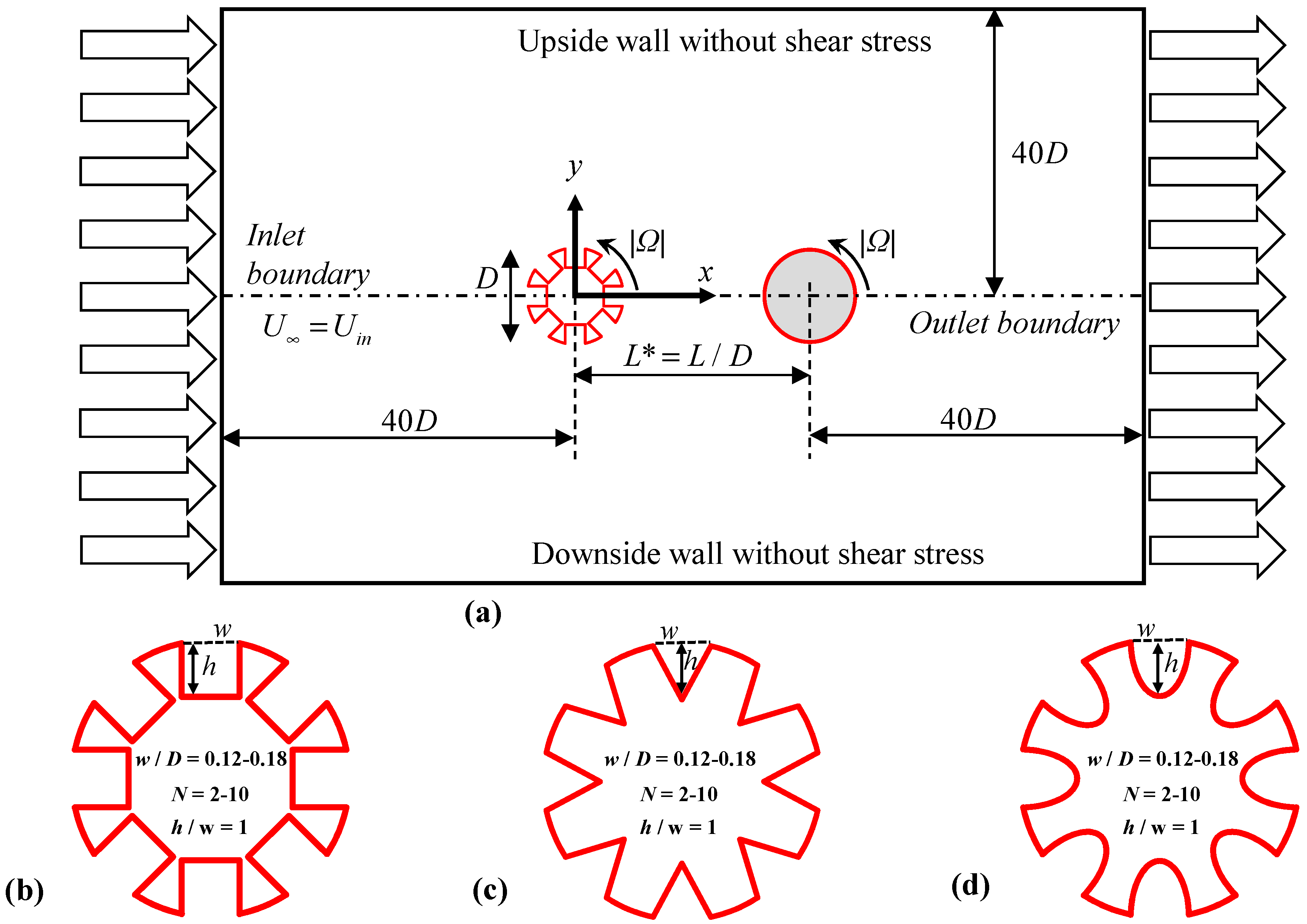
Figure 1. Schematic of the computational domain. (a) Boundary conditions and arrangement of the cylinders, including detailed local views and dimension ratios; (b) Square groove; (c) Triangular groove; (d) Dimpled groove.
Modelling 06 00132 g001
Figure 2. (a) Overall computational domain mesh; (b) Mesh in different regions; (c) Locally magnified details.
Modelling 06 00132 g002
Figure 3. The mesh independence test for grooved cylinders is conducted with a smooth cylinder as the reference, at w/D = 0.12. (a) Square; (b) Triangle; (c) Dimple.
Modelling 06 00132 g003
Figure 4. Mesh independence tests for pressure coefficient and Nusselt number across different geometries. Pressure coefficient: (a) Square; (b) Triangle; (c) Dimple. Nusselt number: (i) Square; (ii) Triangle; (iii) Dimple.
Modelling 06 00132 g004
Figure 5. Comparison of the C ¯ p for a single smooth cylinder at various Reynolds numbers with published experimental and numerical data. (a) Comparison of circumferential pressure distribution on single cylinder at Re = 100 with experimental data (Re = 100 baseline and Re = 107 approximation). (b) Benchmarking of surface pressure coefficient distribution at Re = 200 with literature data (Re = 200 reference and Re = 229 approximation).
Modelling 06 00132 g005
Figure 6. Distributions of the force coefficients of the upstream cylinder (red symbols) and the downstream cylinder (blue symbols) against Ω and Re. (a) The CL of upstream and downstream cylinders; (b) The CD of upstream and downstream cylinders; (c) The < N ¯ u > of upstream and downstream cylinders; (d) The St of upstream and downstream cylinders.
Modelling 06 00132 g006
Figure 7. Streamlines around the tandem cylinders for (I) w/D = 0.12, N = 2 [(a) Ω = −1, (b) Ω = 0, (c) Ω = 1] and (II) w/D = 0.18, N = 10 [(a) Ω = −1, (b) Ω = 0, (c) Ω = 1].
Modelling 06 00132 g007
Figure 8. Lift coefficients around the tandem cylinders for (I) w/D = 0.12, N = 2 [(i) Ω = −1, (ii) Ω = 0, (iii) Ω = 1] and (II) w/D = 0.18, N = 10 [(i) Ω = −1, (ii) Ω = 0, (iii) Ω = 1]. Upstream cylinder lift coefficient time history curves: (a1b1); (a2b2); (a3b3); Downstream cylinder lift coefficient time history curves: (c1d1); (c2d2); (c3d3).
Modelling 06 00132 g008
Figure 9. Drag coefficients around the tandem cylinders for (I) w/D = 0.12, N = 2 [(i) Ω = −1, (ii) Ω = 0, (iii) Ω = 1] and (II) w/D = 0.18, N = 10 [(i) Ω = −1, (ii) Ω = 0, (iii) Ω = 1]. Upstream cylinder drag coefficient time history curves: (a1b1); (a2b2); (a3b3); Downstream cylinder lift coefficient time history curves: (c1d1); (c2d2); (c3d3).
Modelling 06 00132 g009
Figure 10. RMS lift coefficient around the upstream cylinder for w/D against N [(i) Ω = −1, (ii) Ω = 0, (iii) Ω = 1]. Square RMS lift coefficient: (a1a3); Triangle RMS lift coefficient: (b1b3); Dimple RMS lift coefficient: (c1c3).
Modelling 06 00132 g010
Figure 11. RMS lift coefficient around the downstream cylinder for w/D against N [(i) Ω = −1, (ii) Ω = 0, (iii) Ω = 1]. Square RMS lift coefficient: (a1a3); Triangle RMS lift coefficient: (b1b3); Dimple RMS lift coefficient: (c1c3).
Modelling 06 00132 g011
Figure 12. Time-averaged drag coefficient around the upstream cylinder for w/D against N [(i) Ω = −1, (ii) Ω = 0, (iii) Ω = 1]. Square time-averaged drag coefficient: (a1a3); Triangle time-averaged drag coefficient: (b1b3); Dimple time-averaged drag coefficient: (c1c3).
Modelling 06 00132 g012
Figure 13. Time-averaged drag coefficient around the downstream cylinder for w/D against N [(i) Ω = −1, (ii) Ω = 0, (iii) Ω = 1]. Square time-averaged drag coefficient: (a1a3); Triangle time-averaged drag coefficient: (b1b3); Dimple time-averaged drag coefficient: (c1c3).
Modelling 06 00132 g013
Figure 14. Time-averaged pressure coefficient around the upstream cylinder for w/D against N [(i) Ω = −1, (ii) Ω = 0, (iii) Ω = 1]. Square time-averaged pressure coefficient: (a1a3); Triangle time-averaged pressure coefficient: (b1b3); Dimple time-averaged pressure coefficient: (c1c3).
Modelling 06 00132 g014
Figure 15. Time-averaged pressure coefficient around the downstream cylinder for w/D against N [(i) Ω = −1, (ii) Ω = 0, (iii) Ω = 1]. Square time-averaged pressure coefficient: (a1a3); Triangle time-averaged pressure coefficient: (b1b3); Dimple time-averaged pressure coefficient: (c1c3).
Modelling 06 00132 g015
Figure 16. Effect of fluid behavior on isotherm patterns around the tandem cylinders for (I) w/D = 0.12, N = 2 [(a) Ω = −1, (b) Ω = 0, (c) Ω = 1] and (II) w/D = 0.18, N = 10 [(a) Ω = −1, (b) Ω = 0, (c) Ω = 1]. Square isotherm patterns: (a1a3); Triangle isotherm patterns: (b1b3); Dimple isotherm patterns: (c1c3).
Modelling 06 00132 g016
Figure 17. The ratio of the average Nusselt numbers between the upstream and downstream cylinders for w/D against N [(i) Ω = −1, (ii) Ω = 0, (iii) Ω = 1]. Square ratio of the average Nusselt numbers: (a1a3); Triangle ratio of the average Nusselt numbers: (b1b3); Dimple ratio of the average Nusselt numbers: (c1c3).
Modelling 06 00132 g017
Figure 18. The pressure drop between tandem cylinders for w/D as a function of N [(i) Ω = −1, (ii) Ω = 0, (iii) Ω = 1]. Square pressure drop: (a1a3); Triangle pressure drop: (b1b3); Dimple pressure drop: (c1c3).
Modelling 06 00132 g018
Figure 19. The averaged Nusselt number between tandem cylinders for w/D as a function of N [(i) Ω = −1, (ii) Ω = 0, (iii) Ω = 1]. Square averaged Nusselt number: (a1a3); Triangle averaged Nusselt number: (b1b3); Dimple averaged Nusselt number: (c1c3).
Modelling 06 00132 g019
Figure 20. The TPI between tandem cylinders for w/D as a function of N [(i) Ω = −1, (ii) Ω = 0, (iii) Ω = 1]. Square TPI: (a1a3); Triangle TPI: (b1b3); Dimple TPI: (c1c3).
Modelling 06 00132 g020
Figure 21. Distribution of surface Nusselt number on the profile of grooved cylinders under extreme operating conditions.
Modelling 06 00132 g021
Figure 22. The distribution of the surface Nusselt number contour on the downstream cylinder wall under extreme operating conditions. The surface Nusselt number contour of square: (a1a3); The surface Nusselt number contour of triangle: (b1b3); The surface Nusselt number contour of dimple: (c1c3).
Modelling 06 00132 g022
Figure 23. Comparison of average Nusselt number calculated and predicted by Equation (20).
Modelling 06 00132 g023
Table 1. Boundary conditions.
BoundaryVelocityTemperaturePressure
Inlet (constant velocity and temperature)u = U, v = 0T = T p / x = 0 , p / y = 0
Outlet (zero pressure outlet) u / x = 0 , v / x = 0 T / x = 0 p = 0
u / y = 0 , v / y = 0
Cylinder (no slip wall)u = 0, v = 0T = Tw p / x = 0 , p / y = 0
Top and bottom (slip wall) u / y = 0 , v = 0 T / y = 0 p / x = 0 , p / y = 0
Table 2. Comparison of the present research with the literature on rotating and stationary cylinders.
Parameters C ¯ D CL,maxSt
SourcesReΩLiteraturePresentLiteraturePresentLiteraturePresent
Mahir and Altaç [70]100/20001.369 ± 0.029/1.377 ± 0.0481.31/1.30.343/0.6980.3/0.580.172/0.192
Williamson a [71]100/2000------0.164/0.196
Roshko a [72]100/2000------0.16–0.17/0.17–0.19
Norberg a [73]100/2000---0.18 ± 0.54/0.35 ± 0.700.168/0.18–0.197
Yu et al. [74]100/20001.385/1.3530.323/0.6350.167/0.198
Li et al. [42]100/20001.37/1.330.328/0.6320.169/0.195
Kang et al. [75]10011.1041.176−2.49−2.580.1660.164
Stojkovic et al. [76]10011.108−2.500.166
Paramane and Sharma [35]10011.095−2.490.165
a Experimental.
Table 3. Comparing the present mean Nusselt number with literature using empirical formulas and numerical results at Re = 100 and 200.
SourcesRe = 100Re = 200
Present5.237.54
Harimi and Saghafian [77]5.06137.1079
Mahir and Altaç [70]5.1797 ± 0.0037.4747 ± 0.028
Patnana et al. [78]5.153---
Equation (17)5.107.21
Equation (18)5.197.16
Equation (19)5.167.19
Yu et al. [74]5.2127.354
Table 4. Strohal number.
w/DGrooveN = 2N = 4N = 6N = 8N = 10
−101−101−101−101−101
0.12Square0.1560.1710.1560.0790.1720.1560.1560.1720.1570.1560.1720.1570.1570.1720.156
Triangle0.1560.1720.1560.1560.1720.1560.1560.1720.1560.1560.1720.1560.1560.1720.156
Dimple0.1560.1720.1560.1560.1720.1560.1560.1720.1560.1560.1720.1560.1560.1720.156
Smooth0.1680.1730.1680.1680.1730.1680.1680.1730.1680.1680.1730.1680.1680.1730.168
0.14Square0.1560.1720.1560.1570.1730.1570.1580.1720.1560.1560.1730.1570.1570.1720.158
Triangle0.1560.1720.1560.1560.1730.1560.1560.1720.1560.1560.1720.1560.1580.1720.158
Dimple0.1560.1720.1560.1570.1720.1560.1560.1720.1560.1560.1720.1560.1580.1720.158
Smooth0.1680.1730.1680.1680.1730.1680.1680.1730.1680.1680.1730.1680.1680.1730.168
0.16Square0.1560.1730.1560.1560.1730.1560.1560.1730.1570.1580.1720.1580.1580.1720.157
Triangle0.1560.1720.1560.1560.1730.1560.1560.1720.1560.1580.1720.1580.1580.1720.158
Dimple0.1560.1720.1560.1560.1730.1560.1560.1720.1560.1580.1720.1580.1580.1720.158
Smooth0.1680.1730.1680.1680.1730.1680.1680.1730.1680.1680.1730.1680.1680.1730.168
0.18Square0.1570.1720.1560.1560.1730.1580.1560.1720.1560.1570.1730.1580.1570.1730.158
Triangle0.1560.1720.1560.1560.1730.1560.1580.1720.1580.1580.1720.1580.1580.1720.158
Dimple0.1560.1720.1560.1560.1730.1560.1580.1720.1580.1580.1720.1580.1580.1730.158
Smooth0.1680.1730.1680.1680.1730.1680.1680.1730.1680.1680.1730.1680.1680.1730.168
Table 5. Ranges of parameters used in correlation.
ParametersAeqΩN
Ranges0.0072–0.050894−1–12–10
Disclaimer/Publisher’s Note: The statements, opinions and data contained in all publications are solely those of the individual author(s) and contributor(s) and not of MDPI and/or the editor(s). MDPI and/or the editor(s) disclaim responsibility for any injury to people or property resulting from any ideas, methods, instructions or products referred to in the content.