Article

Enhanced Cooling Performance in Cutting Tools Using TPMS-Integrated Toolholders: A CFD-Based Thermal-Fluidic Study

1
School of Mechanical Engineering, Shandong University, Jinan 250061, China
2
State Key Laboratory of Advanced Equipment and Technology for Metal Forming, Shandong University, Jinan 250061, China
3
Key Laboratory of High Efficiency and Clean Mechanical Manufacture of Ministry of Education, Jinan 250061, China
4
Key National Demonstration Center for Experimental Mechanical Engineering Education, Jinan 250061, China
5
Shandong Key Laboratory of High Performance Tools and System, Jinan 250061, China
6
School of Mechanical, Electrical & Information Engineering, Shandong University, Weihai 264209, China
*
Author to whom correspondence should be addressed.
Modelling 2025, 6(3), 73; https://doi.org/10.3390/modelling6030073
Submission received: 29 June 2025 / Revised: 23 July 2025 / Accepted: 25 July 2025 / Published: 28 July 2025

Abstract

The efficient thermal management of cutting tools is critical for ensuring dimensional accuracy, surface integrity, and tool longevity, especially in the high-speed dry machining process. However, conventional cooling methods often fall short in reaching the heat-intensive zones near the cutting inserts. This study proposes a novel internal cooling strategy that integrates triply periodic minimal surface (TPMS) structures into the toolholder, aiming to enhance localized heat removal from the cutting region. The thermal-fluidic behaviors of four TPMS topologies (Gyroid, Diamond, I-WP, and Fischer–Koch S) were systematically analyzed under varying coolant velocities using computational fluid dynamics (CFD). Several key performance indicators, including the convective heat transfer coefficient, Nusselt number, friction factor, and thermal resistance, were evaluated. The Diamond and Gyroid structures exhibited the most favorable balance between heat transfer enhancement and pressure loss. The experimental validation confirmed the CFD prediction accuracy. The results establish a new design paradigm for integrating TPMS structures into toolholders, offering a promising solution for efficient, compact, and sustainable cooling in advanced cutting applications.

1. Introduction

The efficient thermal management of cutting tools is essential for maintaining dimensional accuracy and surface integrity and prolonging tool life, especially under high-speed or dry machining conditions [1]. The generated heat is primarily concentrated near the tool–chip interface, leading to severe thermal loads on the cutting edge. This thermal concentration, if not adequately dissipated, causes a significant localized temperature rise, which can lead to tool softening, loss of hardness, plastic deformation, and even catastrophic failure during operation [2,3,4]. Furthermore, high thermal gradients within the cutting tool not only deteriorate its mechanical performance but also result in unpredictable dimensional deviations, adversely affecting surface finish and part accuracy [5,6]. Various external cooling and lubrication strategies have been employed in the machining industry to mitigate thermal damage [7]. Conventional cooling techniques, such as flood cooling [1,8,9], high-pressure jet cooling [10,11], or minimum quantity lubrication [12,13], have proven effective to some extent in lowering tool temperatures and reducing friction at the tool–workpiece interface. However, their cooling performance is often limited by poor accessibility to the actual heat generation zones, particularly in complex geometries or high-speed dry cutting operations [14]. Moreover, environmental concerns and the cost of coolant disposal have driven the demand for more sustainable and localized cooling solutions in modern manufacturing [15].
With the advancement of aerospace, thermal power generation, and electronics, enhanced heat transfer in compact heat exchangers has been extensively investigated [16]. High-performance miniature heat sinks have been developed by incorporating phase change materials (PCMs) or flow channels based on triply periodic minimal surface (TPMS) structures to meet demanding thermal management requirements under space constraints [17,18]. PCMs regulate temperature by absorbing heat during phase transitions, but suffer from low thermal conductivity [19]. In contrast, TPMS structures enhance convective heat transfer by directing fluid flow, offering a more efficient thermal management solution for cutting tools. Research attention has increasingly turned toward architected porous structures with enhanced thermal-fluidic characteristics to address the limitations of conventional channel configurations. Triply periodic minimal surfaces (TPMS) represent a class of mathematically defined geometries that feature continuous, smooth, and non-self-intersecting surfaces extended periodically in three dimensions [20,21]. Due to their inherently high surface-to-volume ratios and spatially complex topology, TPMS structures offer superior performance in convective heat transfer by increasing the contact area and promoting flow mixing [22,23]. Compared to traditional straight or serpentine channels, TPMS-based flow passages introduce tortuous paths and multiple flow bifurcations, which enhance turbulence even at low Reynolds numbers and contribute to more uniform temperature fields throughout the structure. In recent years, TPMS geometries such as Gyroid, Diamond, Schwarz-D, and Fischer–Koch S have been extensively explored in the design of next-generation heat exchangers, thermal energy absorbers, and high-performance heat sinks [24,25].
TPMS structures are difficult to fabricate using conventional manufacturing methods due to their geometric complexity. Additive manufacturing (AM), which enables near-net-shape fabrication from powders, resins, or filaments, offers a feasible solution. In particular, its capability to construct overhanging and self-supporting features makes it well-suited for the realization of TPMS architectures [26]. With the advancement of AM technologies, resin [27], metal [28], ceramic [29], and composite [30] materials have all been successfully used to fabricate TPMS structures. It has become technically feasible to fabricate complex TPMS geometries within metallic components with high precision [22,31]. This technological progress opens up new design possibilities for cutting tools. Despite these promising developments, research efforts on applying TPMS structures to cutting tool cooling remain scarce. Existing studies have primarily focused on macro-scale heat exchangers and cold plates, with limited attention given to the thermal performance of TPMS geometries in complex engineering environments.
To address the limitations of conventional internal cooling methods, this study proposes a novel cooling strategy by embedding TPMS structures into the toolholder to enhance local heat extraction from the cutting insert. A series of computational fluid dynamics (CFD) simulations was conducted to evaluate the thermal-fluidic performance of various TPMS configurations under typical cutting heat loads and coolant flow conditions. The findings aim to provide a theoretical basis and design insights for the development of next-generation internally cooled cutting tools that leverage the geometric and thermal advantages of TPMS structures.

2. Methods

In this section, the overall methodology for evaluating the thermal-fluidic performance of TPMS-integrated toolholders is presented. Four representative TPMS topologies—Gyroid, Diamond, I-WP, and Fischer–Koch S—were embedded into a simplified toolholder model. The geometric models were constructed using periodic unit cells with identical porosity and bounding dimensions to ensure a fair comparison. Computational fluid dynamics (CFD) simulations were performed to analyze coolant flow and heat transfer under varying inlet velocities. Key thermal–hydraulic performance indicators—including Nusselt number, convective heat transfer coefficient, pressure drop, and thermal resistance—were extracted and compared. A mesh independence study and experimental validation were also conducted to verify the accuracy of the numerical results. The following subsections detail the geometric modeling, simulation setup, validation approach, and performance evaluation criteria.

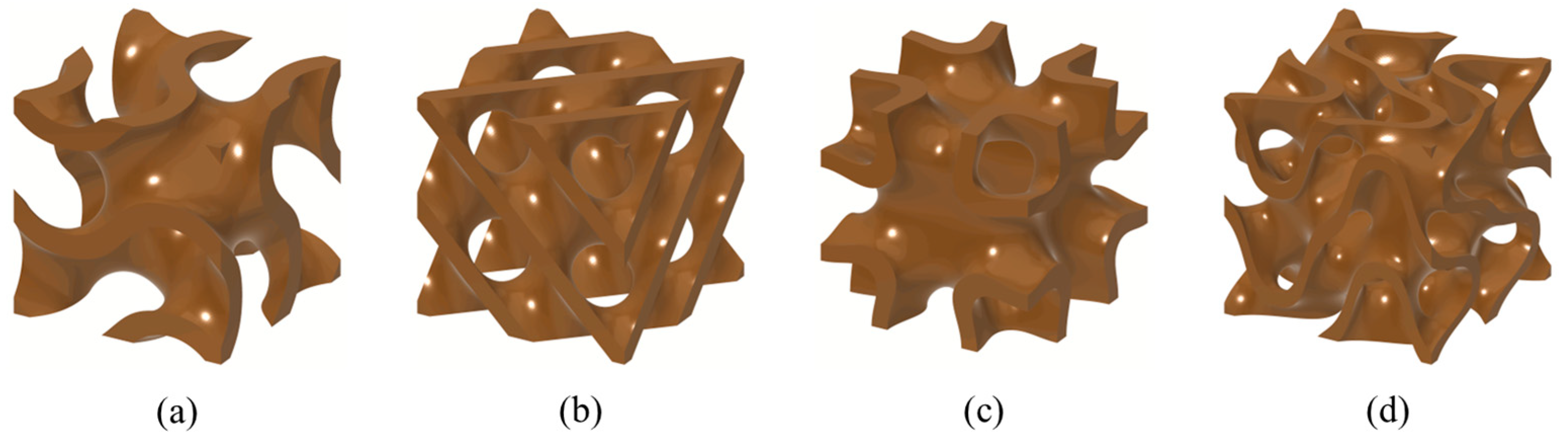
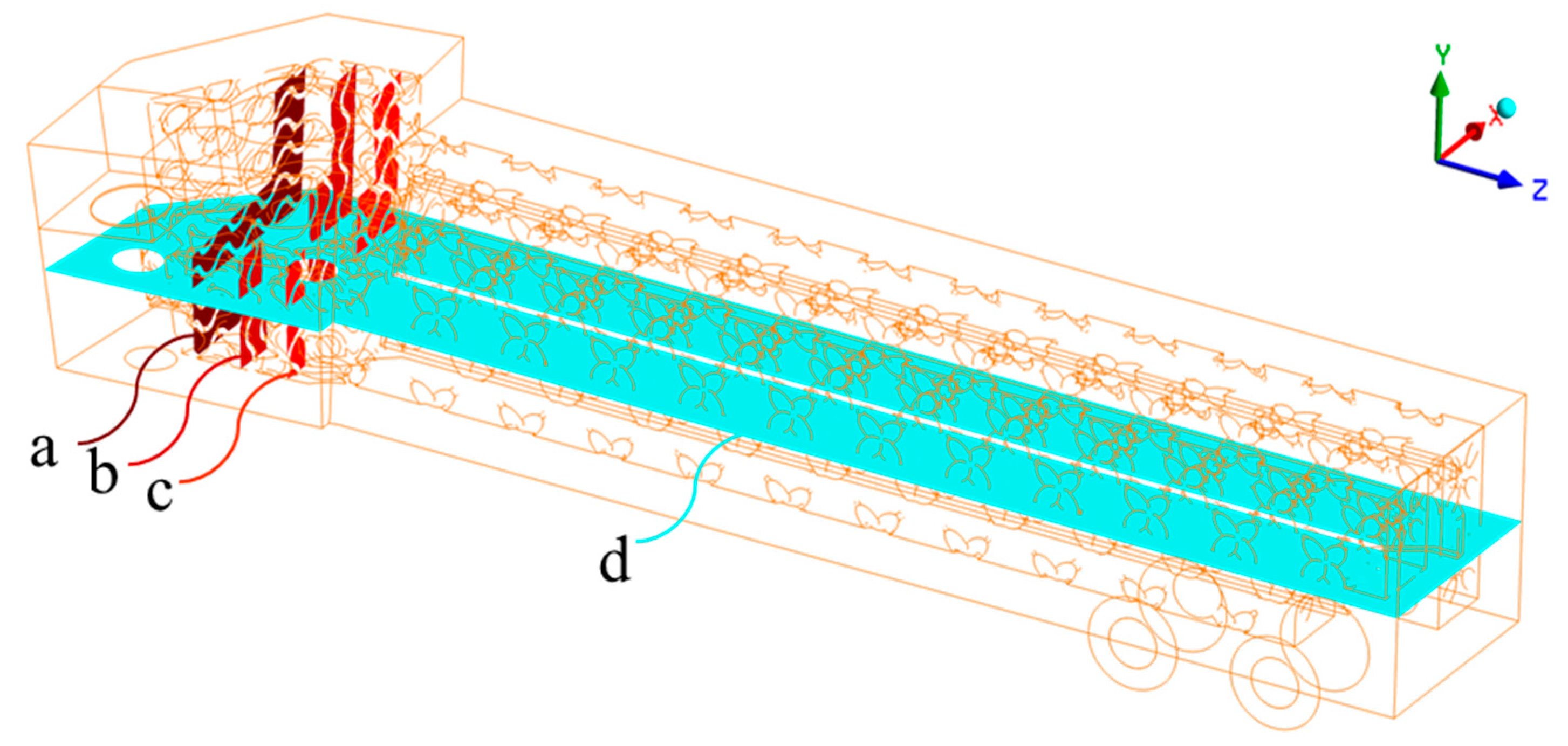
2.1. Geometric Model Construction

As shown in Figure 1, four representative triply periodic minimal surface (TPMS) structures—Gyroid, Diamond, I-WP, and Fischer–Koch S—were selected to construct internal cooling geometries for the cutting tool. These structures were mathematically defined using their respective implicit surface equations, which allow for precise control over key geometric parameters such as porosity (volume fraction) and unit cell size. The implicit equations for the four TPMS types used in this study are given as follows [32,33,34]:
Gyroid:
ϕ Gyroid   ( x , y , z ) = s i n ( 2 π x L   ) c o s ( 2 π y L   ) + s i n ( 2 π y L   ) c o s ( 2 π z L   ) + s i n ( 2 π z L   ) c o s ( 2 π x L   ) C = 0
Diamond:
ϕ Diamond   ( x , y , z ) = s i n ( 2 π x L   ) s i n ( 2 π y L   ) s i n ( 2 π z L   ) + s i n ( 2 π x L   ) c o s ( 2 π y L   ) c o s ( 2 π z L   ) + c o s ( 2 π x L   ) s i n ( 2 π y L   ) c o s ( 2 π z L   ) + c o s ( 2 π x L   ) c o s ( 2 π y L   ) s i n ( 2 π z L   ) C = 0
I-WP (Infinite Periodic Wrapped Package):
ϕ I - WP   ( x , y , z ) = c o s ( 2 π x L   ) + c o s ( 2 π y L   ) + c o s ( 2 π z L   ) s i n ( 2 π x L   ) s i n ( 2 π y L   ) s i n ( 2 π y L   ) s i n ( 2 π z L   ) s i n ( 2 π z   L ) s i n ( 2 π x L   ) C = 0
Fischer–Koch S:
ϕ F - Koch   ( x , y , z ) = c o s ( 2 π x   L ) s i n ( 2 π y L   ) + c o s ( 2 π y L   ) s i n ( 2 π z L   ) + c o s ( 2 π z L   ) s i n ( 2 π x L   ) C = 0
In the above expressions: x, y, and z are spatial coordinates, L is the unit cell size, set as 6 mm in all directions, and C is a constant threshold value that controls the solid–void distribution, which is tuned for each structure to achieve a consistent solid volume fraction of 30%.
The MCLNR2525M12 toolholder was used as the baseline toolholder to enable comparison with the commonly used toolholder. The computer-aided design model of the toolholder shell with a thickness of 3 mm was constructed based on the dimensions of the BT. An array of TPMS with the dimensions 30 mm × 30 mm × 30 mm was constructed (Figure 2a). This array was placed inside the internal cavity of the toolholder, close to the insert installation area. The placement aimed to enhance the cooling performance in the region with the highest thermal load during cutting. As shown in Figure 2, the inlet and outlet of the coolant channel, each with a diameter of 6 mm, were located at the tail of the toolholder to avoid interference from the fluid circulation system during cutting. BCC (Body-Centered Cubic) lattice structures with a rod diameter of 2 mm were incorporated into the flow channels to enhance their structural strength (Figure 2b). A 1 mm cavity was introduced between the inlet and outlet channels to serve as a thermal buffer and reduce mutual thermal interference (Figure 2c). With this model, the coolant enters through the inlet and flows along the toolholder toward the cutting zone. It reverses direction and exits through the return channel, after providing forced cooling in the TPMS region (Figure 2d). The hollow insulating layer separating the forward and return flow paths helps minimize energy loss and enhances the overall efficiency of the cooling system. Table 1 presents the geometric characteristics of the chosen TPMS structures, detailing parameters such as channel volume Vc, surface area Ac, TPMS unit cell volume VTPMS, unit cell surface area ATPMS, specific surface area SSA, wall thickness, and hydraulic diameter Dh. The calculation of the hydraulic diameter Dh follows the expression given in Equation (5):
D h = 4 V c / A c

2.2. CFD Modeling and Boundary Settings

Steady-state computational fluid dynamics (CFD) simulations were carried out using ANSYS Fluent (version 2024 R2) to investigate the thermal–fluid performance of the internal cooling channels in the TPMS-integrated toolholder structure. The working fluid selected was liquid water. A total of 316 L stainless steel was assigned as the material for all solid domains of the toolholder, while the cutting insert was modeled using WC-Co (tungsten carbide–cobalt composite), in line with typical industrial applications. The thermal properties of the materials involved in the simulation—including liquid water, 316 L stainless steel, and WC-Co—are listed in Table 2. Spatial gradient terms were calculated using a cell-based least-squares approach, ensuring numerical stability and accuracy. For convective transport, the QUICK (Quadratic Upstream Interpolation for Convective Kinematics) scheme was applied to achieve higher-order accuracy, and second-order discretization was used for the pressure term. The coupling between the velocity and pressure fields was resolved using a pressure-based solver algorithm. Heat transfer between the fluid and solid domains was modeled using the thermal energy formulation, which provides accurate resolution of heat exchange across fluid–solid interfaces. The Shear Stress Transport (SST) turbulence model was employed to capture the complex turbulent flow structures, especially near walls and in separated regions. The overall thermal–fluid analysis was governed by the conservation equations for mass, momentum, and energy, which collectively describe the behavior of the coupled system. These governing equations are expressed as follows [35]:
Continuity equation:
( ρ . u ) = 0
This equation ensures mass conservation, where ρ is the fluid density (kg/m3) and u is the velocity vector (m/s).
Momentum equation:
( ρ u u ) = p + μ eff [   ( . u + . u T ) 2 3 . u ]
Here, the left-hand-side term represents the outer (tensor) product of the velocity vector with itself, p is the static pressure (Pa), and μeff is the effective dynamic viscosity, including both laminar and turbulent contributions.
Energy equation for the fluid domain:
( ρ u h ) = ( λ eff   T )
Energy equation for the solid domain:
( λ s   T ) = 0
where h is the specific enthalpy (J/kg), T is the temperature (K), λeff is the effective thermal conductivity in the fluid, including turbulent effects, and λs is the thermal conductivity of the solid material (W/(m·K)).
The Shear Stress Transport (SST) k-ω model was employed to resolve the complex internal turbulence within the TPMS region. This model effectively blends the near-wall sensitivity of the k-ω formulation with the free-stream stability of the k-ε model. The governing equations are as follows [36]:
Turbulence kinetic energy (k) equation:
( ρ k ) t   + ( ρ u k ) = P k   β ρ k ω + [ ( μ + σ k   μ t   ) k ]
Specific dissipation rate (ω) equation:
( ρ ω ) t   + ( ρ u ω ) = α ω k   P k   β ρ ω 2 + [ ( μ + σ ω   μ t   ) ω ] + 2 ( 1 F 1   ) ρ σ ω 2   1 ω   k ω
where Pk is the turbulence production term, μt is the turbulent (eddy) viscosity, given by μt = ρa1k/max (a1ω,SF2), α, β, β*, σk, σω, a1 are model constants, S is the strain-rate magnitude, and F2 are blending functions for the SST model.
This modeling approach enables accurate resolution of heat and momentum transport in both boundary-layer-dominated and separated flow regions within the TPMS cooling channels. It is particularly suitable for the sharply curved and spatially periodic geometries of TPMS structures.
The boundary conditions are summarized in Table 3. Five different inlet velocities were considered—0.2, 0.5, 1.0, 1.6, and 2.5 m/s—to evaluate the cooling performance of the TPMS- integrated toolholder under varying operating conditions. Liquid water at an initial temperature of 273.15 K was used as the coolant. The inlet was defined as a velocity inlet, while the outlet was specified as a pressure outlet with a gauge pressure of 0 Pa. The flow was assumed to be incompressible and steady. A volumetric heat source of 200 W was applied to the region corresponding to the cutting insert to simulate the heat generated during the machining process. This region has a rhombic base area of 151 mm2 and a height of 9.6 mm. To account for imperfect thermal contact between the insert and the toolholder, a thermal contact resistance of 10,000 (m2·K)/W was defined at the insert–toolholder interface. The remaining external surfaces of the toolholder were treated as convective boundaries, with the ambient temperature set to 300 K. This method provides a more realistic representation of the thermal load concentrated near the cutting edge. These boundary conditions aim to replicate the thermal–fluid environment encountered in dry or near-dry cutting operations, where localized heat buildup occurs at the tool–chip interface. The configuration allows for an evaluation of how effectively the internal TPMS cooling structure dissipates heat from the cutting zone.

2.3. Grid Independence and Model Validation

High-quality mesh generation is essential for ensuring the accuracy and reliability of computational fluid dynamics (CFD) simulations. Independent meshing strategies were employed for the thermal–fluid domains due to their distinct geometric features and physical modeling requirements. The CFD domain—especially the regions containing TPMS structures—required significantly finer meshes to resolve complex internal geometries, steep thermal gradients, and near-wall turbulence behavior. Mesh independence studies were conducted for CFD simulations to ensure the accuracy and reliability of the simulation results. In the CFD simulation, structured hexahedral meshes were generated for both the fluid and solid regions to balance computational efficiency with solution accuracy. To accurately capture the near-wall flow behavior, inflation layers were added near the solid surfaces. A total of seven layers were generated, with a growth rate of less than 1.2. These layers were designed to achieve a dimensionless wall distance (Y+) close to 1. Mesh convergence was assessed by monitoring the temperature and pressure drop between the inlet and outlet at a representative flow velocity of 1 m/s. The variations in these parameters remained within 2% compared to the finest mesh solution, confirming numerical stability. Based on this analysis, the final meshes—ranging from approximately 13.82 to 16.02 million elements—were adopted for all CFD cases, corresponding to each TPMS structure: Gyroid (13.82 M), Diamond (14.08 M), I-WP (13.97 M), and Fischer–Koch S (16.02 M). The details of the mesh sensitivity study are summarized in Table 4.
A TPMS-based toolholder with a comparable channel internal structure was tested to verify the reliability of the CFD methodology adopted in this study. The experimental setup is illustrated in Figure 3. The toolholder was placed on a thermostatically controlled platform maintained at 393.15 K, while liquid water was introduced as the coolant at various inlet flow rates. A Type K thermocouple was embedded at a predefined surface location on the toolholder to measure the steady-state temperature. CFD simulations with the same boundary conditions as the experimental setup were conducted, enabling a direct comparison of the measured and simulated temperatures at the same location. The comparison between simulated and measured temperatures under different flow conditions is presented in Table 5. The slight deviations can be ascribed to simplified thermal boundary assumptions and the presence of contact resistance or heat losses in the experimental setup, which are difficult to fully replicate in the simulation. The close agreement between the two confirms that the numerical model provides reliable predictions of heat transfer and fluid behavior within TPMS-based cooling structures.

2.4. Thermal–Hydraulic Evaluation Parameters

Thermal–hydraulic evaluation parameters were adopted to quantify the thermal and hydraulic performance of the TPMS-integrated toolholder. These include the Nusselt number (Nu) and Colburn j-factor (j) for evaluating convective heat transfer behavior, and the Reynolds number (Re) and friction factor (f) for assessing flow dynamics and pressure resistance. The average convective heat transfer coefficient (h) was also introduced to represent the thermal exchange intensity across solid–fluid interfaces.
The Reynolds number was defined using the volume-averaged velocity uavg:
R e = ρ u avg D h μ
The friction factor f was calculated from the pressure drop Δp along the flow path of length L. Considering the reciprocating flow within the TPMS structure, L is taken as twice the axial length (L = 300 mm):
f = 2 D h Δ p ρ u avg 2 L
The convective heat transfer coefficient h quantifies the heat exchange between the solid wall and fluid, calculated by the heat flux q transferred through the heated surface area As, the wall temperature Tw, and the volume-averaged fluid temperature Tavg:
h = q A s T w T avg
The Nusselt number (Nu):
N u = h D h k
The Colburn j-factor provides a normalized measure of convective heat transfer performance relative to flow conditions, defined as:
j = N u R e P r 1 / 3
where Pr is the Prandtl number of the fluid.
Thermal resistance Rth describes the effectiveness of the cooling system, expressed as the temperature difference between the heated surface and fluid divided by the heat transfer rate Q:
R th   = T w   T avg Q    

3. Results and Discussion

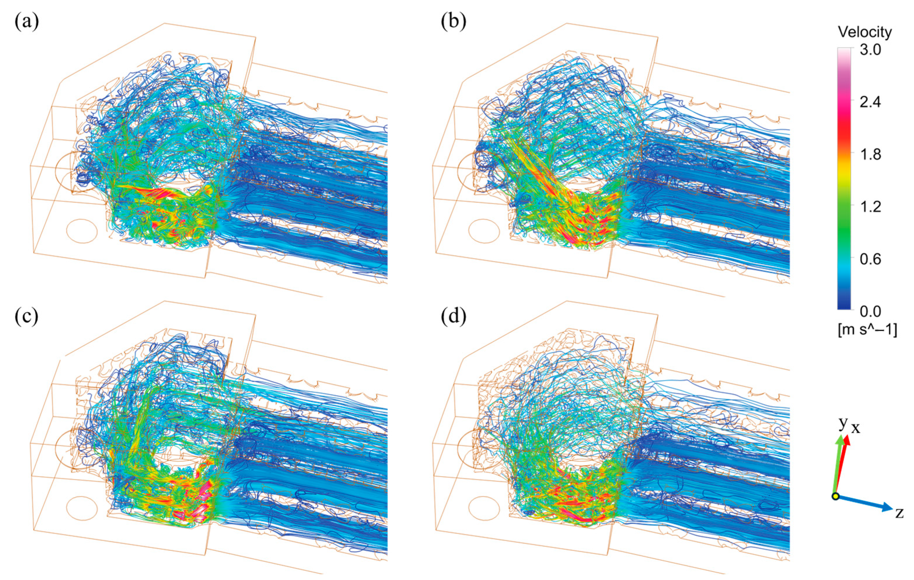
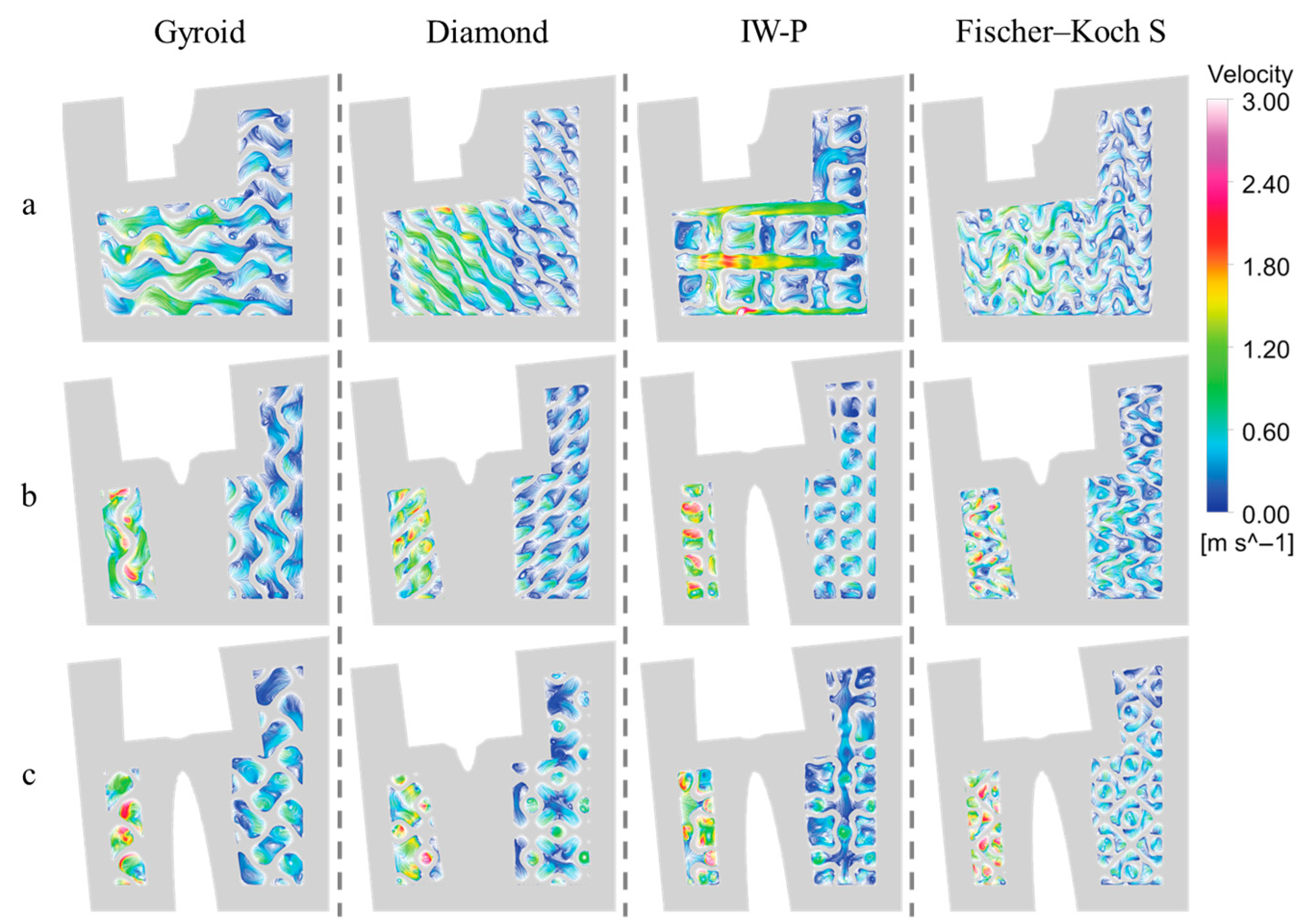
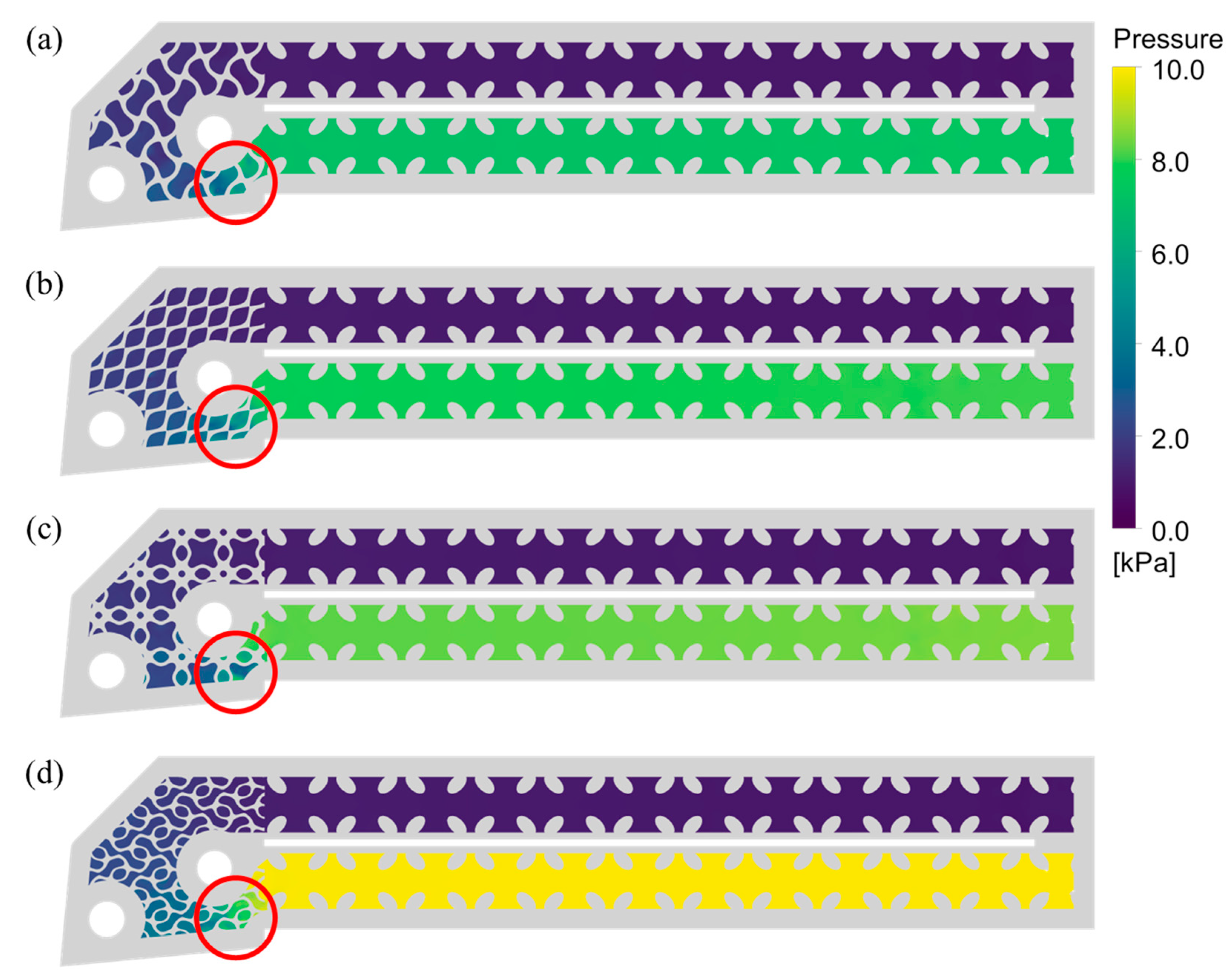
3.1. Flow Field Characteristics and Internal Mixing

Figure 4 shows the streamline distributions for the four TPMS-integrated toolholders. During the flow process, the coolant is constantly disturbed by the three-dimensional curvature of the internal surfaces. This leads to frequent changes in flow direction. The complexity of the topology enhances internal mixing and disrupts boundary layer development. As a result, the fluid undergoes periodic acceleration and deceleration. These effects promote vortex generation and increase overall turbulence intensity. Different TPMS topologies produce distinct flow patterns, which influence both turbulence intensity and flow resistance. Sharp changes in flow velocity are mainly observed in the narrow channel sections of the cavity. While TPMS structures contribute to flow disturbance, their effect is weaker compared to the sudden contraction of channel volume. Therefore, in TPMS cooling designs, the hydraulic performance of the available space should be a primary consideration.
Cross-sectional views provide further insight into the flow behavior. As shown in Figure 5, four cross-sections were selected along the toolholder. Sections b and c correspond to the narrow flow regions identified in Figure 4. Figure 6 presents the flow characteristics on sections a, b, and c for each structure. The cross-sectional area at the narrow region is much smaller than that in the regular flow passages. Combined with the complex spatial occupation of the TPMS surfaces, this leads to significant flow loss. These observations highlight the dominant role of spatial hydraulic design in engineering applications of TPMS structures. Recirculation zones and vortices are observed in regions where the fluid encounters geometric obstructions and is forced to change its path. In these regions, the coolant flows around the surfaces repeatedly, undergoing separation and recombination. This behavior promotes secondary flow, shear layers, and vortex formation. These features help to disrupt the boundary layer and enhance heat transfer.
The periodic structure of the TPMS channels introduces repeated flow disturbances along the flow direction. This causes periodic variations in the fluid motion, confirming that the design objective has been achieved. The pressure distribution in cross-section d (Figure 7) provides information on the channel behavior in the flow direction. The overall flow field in the TPMS region is shaped by its irregular surface geometry. Pressure losses are mainly concentrated in the narrow regions and within the TPMS channels. In the TPMS regions, the pressure drop shows a relatively uniform gradient. However, in the narrow channel sections, the pressure drop is significantly more abrupt.

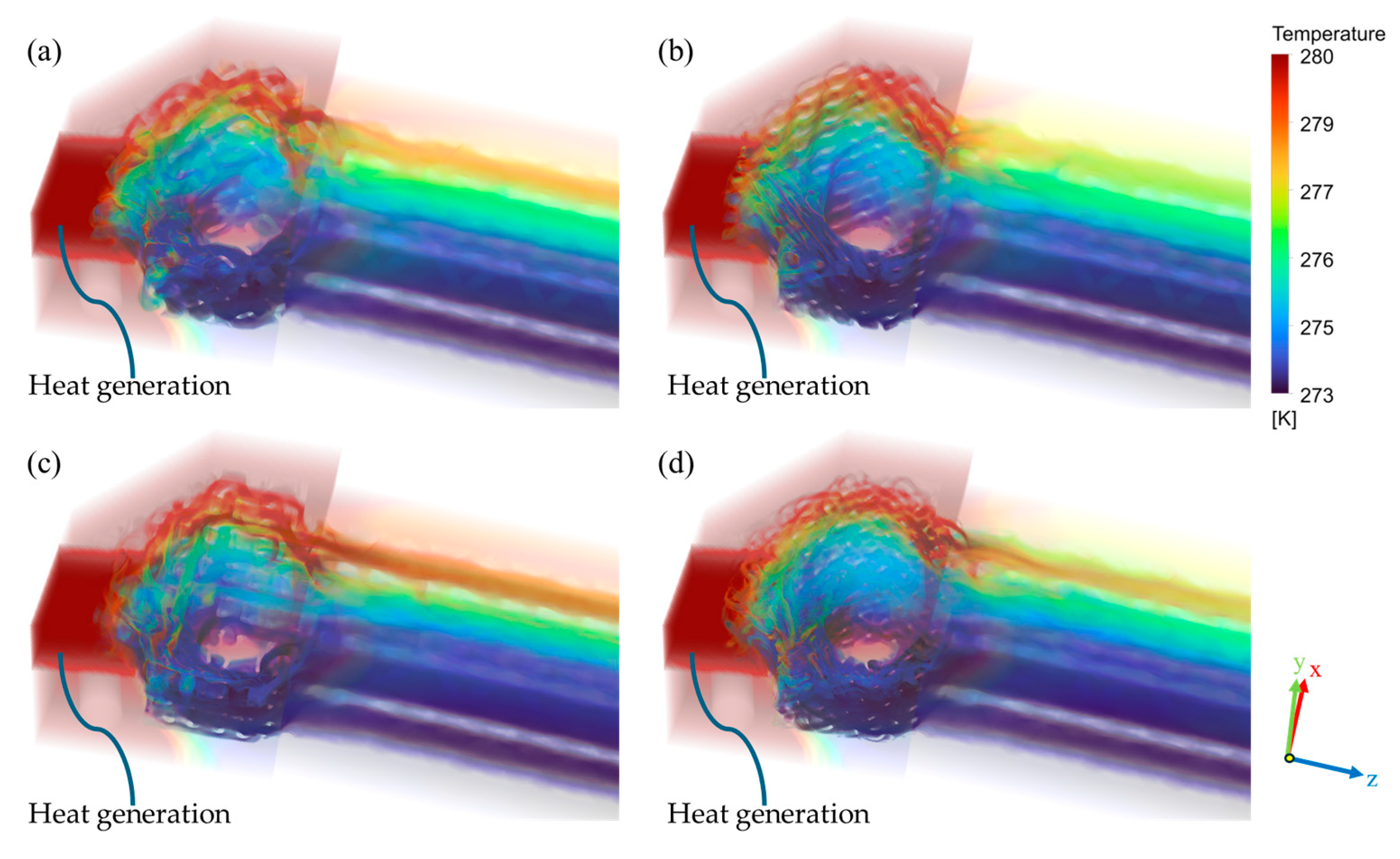
3.2. Temperature Distribution and Thermal Field Analysis

This section investigates the heat transfer behavior of TPMS-integrated toolholders. Figure 8 presents the temperature distribution of the toolholder and the internal flow channels obtained through CFD-based thermal–fluid coupling analysis. Under the predefined boundary conditions, a stable temperature difference is observed between the inlet and outlet of the cooling channel. This confirms the effective heat transfer capability of the TPMS structure. As the coolant travels through the internal channels, the low-temperature fluid in the forward path and the returning high-temperature fluid fully interact with the TAT structure. The turbulent zones generated by the TPMS geometry enhance convective heat transfer, achieving efficient thermal regulation. However, several regions with poor coolant circulation are visible in Figure 8 and Figure 9. These areas exhibit locally elevated temperatures due to insufficient connectivity to the main flow path. Most of these zones are located near abrupt geometric transitions in the toolholder, where the flow resembles parallel dead-end branches—an inherent limitation when using TPMS structures for internal channeling. Such complex channel geometries may lead to low-velocity regions that promote fluid stagnation or even bubble accumulation, which can further deteriorate local heat dissipation. This issue should be considered when optimizing TPMS-based cooling designs for practical applications.
Additional thermal details can be observed in Figure 9, which shows the temperature distribution on cross-section d. Along the flow direction, the fluid temperature consistently increases for all four TPMS configurations. This confirms that effective heat transfer occurs between the fluid and the cutting insert. All TPMS structures produce a clear wall-to-core temperature gradient due to their complex surface geometry. This gradient promotes convective heat transfer. In the solid part of the toolholder, especially in the TPMS region, high thermal gradients are also present. This confirms the enhanced thermal performance of the proposed design. The thermal isolation between the inlet and outlet channels effectively separates hot and cold fluids. It prevents unwanted thermal mixing and improves overall cooling efficiency.

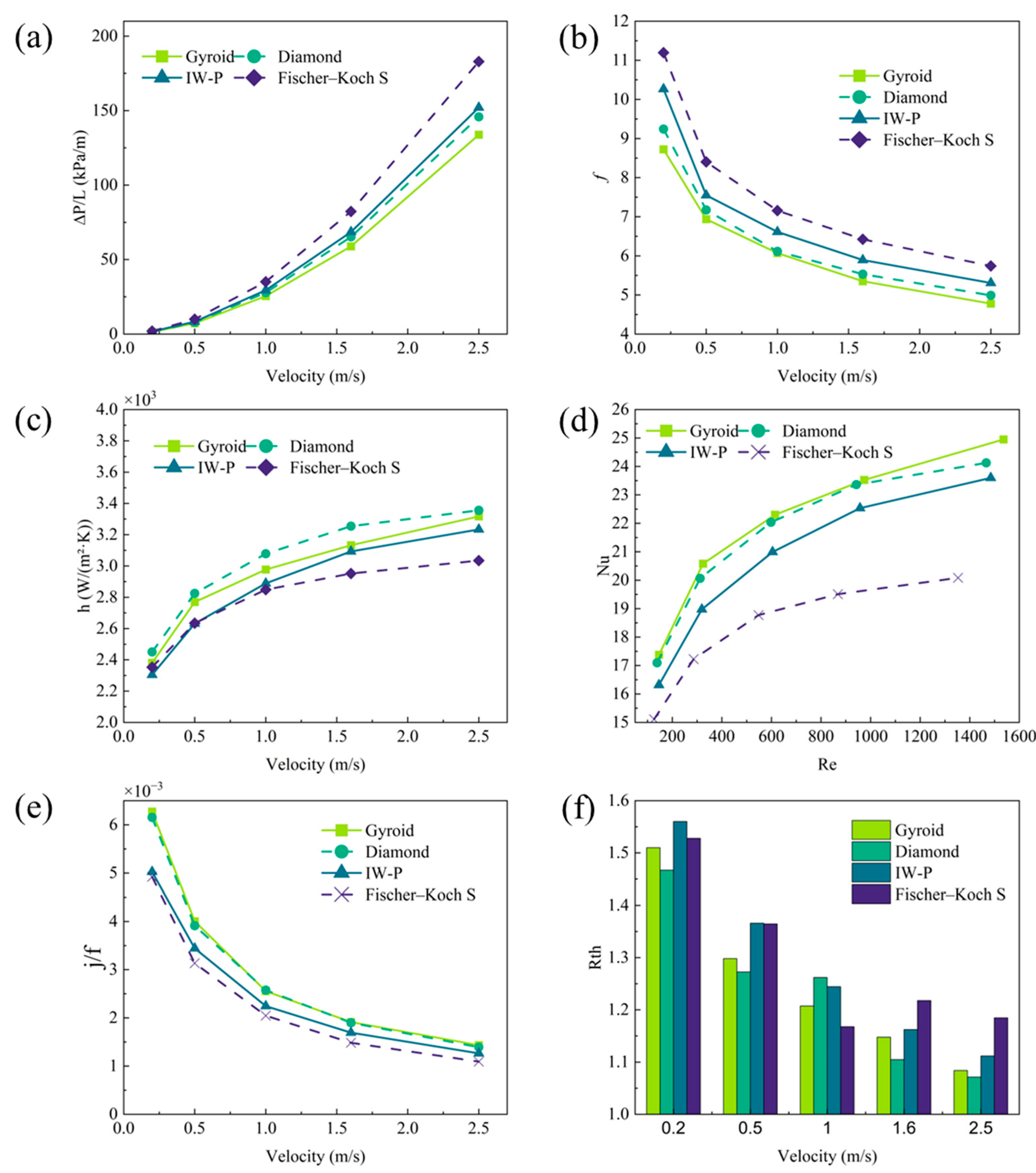
3.3. Evaluation of Thermo-Hydraulic Performance

This section presents a quantitative evaluation of the thermo-hydraulic performance of the TPMS-integrated toolholders based on the previously defined performance parameters. As shown in Figure 10, the heat transfer and flow resistance characteristics of the four TPMS toolholders were investigated under five inlet velocities, ranging from 0.2 to 2.5 m/s.
Figure 10a illustrates the variation of pressure drop (ΔP) with inlet velocity. The pressure drop ΔP increases nonlinearly with velocity due to enhanced flow inertia. Among the four structures, Fischer–Koch S exhibits the highest pressure drop at all velocities, which indicates significant internal flow resistance. In contrast, the Gyroid and Diamond structures consistently produce lower pressure losses, demonstrating more favorable flow characteristics for practical application. The friction factor (f), shown in Figure 10b, decreases consistently with an increasing flow rate for all four TPMS structures. This inverse relationship is characteristic of internal flow within the transitional regime, where inertial effects begin to emerge but turbulence is not yet fully developed. The Reynolds numbers in this study range approximately from 147 to 1536, which confirms that the flow remains within the laminar-to-transitional range across all tested conditions. The Fischer–Koch S structure maintains the highest f values, whereas Gyroid and Diamond show notably lower values. The lower f values of Gyroid and Diamond indicate reduced flow resistance, which can be attributed to their more continuous and less tortuous internal channel geometry. These findings emphasize the importance of TPMS topology on flow efficiency under transitional flow conditions and suggest that Gyroid and Diamond offer better hydraulic performance for internal cooling applications.
The convective heat transfer coefficient (h) is presented in Figure 10c. Diamond exhibits the highest heat transfer rates across all flow velocities, followed by Gyroid and I-WP. Fischer–Koch S consistently demonstrates the poorest thermal performance. This trend is also reflected in the Nusselt number (Nu) profiles plotted against Reynolds number in Figure 10d. Diamond and Gyroid structures show substantial enhancement in Nu, indicating effective disruption of thermal boundary layers and vigorous mixing. These differences in thermal performance can be attributed to the geometric features of each TPMS topology. The Diamond structure, with its well-distributed curvature and continuous interconnecting channels, promotes strong fluid mixing and repeated disruption of thermal boundary layers, thereby improving heat transfer efficiency. The Gyroid, which also possesses a smooth and interconnected morphology, exhibits similar but slightly lower performance. In contrast, the Fischer–Koch S structure presents a more tortuous and segmented flow path, which may suppress coherent mixing and lead to the formation of stagnant zones, reducing its overall heat transfer capability. Figure 10e compares the j/f performance metric, which quantifies the trade-off between heat transfer enhancement and pressure loss. Gyroid and Diamond structures exhibit the highest values across the flow velocity range, indicating their efficiency in achieving high thermal performance with minimal pumping penalty. Fischer–Koch S performs the worst, suggesting that its complex geometry does not translate into an effective thermal–fluid design. The results highlight that TPMS geometries with smoother transitions and more uniform flow distribution are better suited for enhancing convective heat transfer under transitional flow conditions.
Figure 10f presents the thermal resistance Rth of the four TPMS- integrated toolholders under varying coolant velocities. Thermal resistance is a critical parameter that quantifies the system’s ability to transfer heat from the solid domain to the coolant, defined as the temperature difference between the heated surface and the fluid volume average, normalized by the heat input. Lower values of Rth indicate better cooling performance. As shown, all four structures exhibit a monotonic decrease in Rth with increasing velocity, reflecting the enhanced convective heat transfer at higher flow rates. Among them, the Diamond structure achieves the lowest Rth across the entire velocity range, followed closely by Gyroid, indicating their superior cooling effectiveness. The Fischer–Koch S structure maintains the highest thermal resistance, especially at low velocities, suggesting insufficient heat removal due to suboptimal flow and thermal boundary layer interaction. At a low inlet velocity of 0.2 m/s, the Diamond and Gyroid structures reduce thermal resistance by approximately 30–40% compared to the Fischer–Koch S design. This performance gap persists, though diminishes, at higher velocities. The I-WP structure offers intermediate thermal resistance values, confirming its moderate overall thermal behavior. These results reinforce the findings from heat transfer coefficient and Nusselt number comparisons, confirming that Diamond and Gyroid structures are the most effective geometries for minimizing thermal resistance and maximizing toolholder cooling efficiency.

4. Conclusions

This study conducted a comprehensive thermal–fluid analysis of four TPMS-integrated toolholder designs for internal cooling applications. The key conclusions are as follows:
  • The complex three-dimensional curvature of TPMS structures effectively disturbs the coolant flow, promoting vortex formation and enhancing turbulence intensity. This leads to improved convective heat transfer through boundary layer disruption.
  • Among the four TPMS topologies, the Fischer–Koch S structure exhibits the highest flow resistance and pressure drop, resulting in poorer thermal performance. In contrast, the Gyroid and Diamond structures demonstrate superior hydraulic efficiency with lower pressure losses.
  • The Diamond structure achieves the highest convective heat transfer coefficients and the lowest thermal resistance across the tested velocity range, indicating its outstanding cooling effectiveness. Gyroid performs closely behind Diamond, both outperforming the I-WP and Fischer–Koch S structures.
  • Thermal isolation between the inlet and outlet channels in TPMS toolholders effectively reduces thermal mixing, thereby enhancing overall cooling efficiency. The trade-off metric confirms that Gyroid and Diamond topologies provide the best balance between heat transfer enhancement and flow resistance, making them the most promising designs for advanced internal cooling tools.
These findings provide a valuable design basis for future high-performance, internally cooled cutting tool systems. The integration of additively manufacturable TPMS structures offers a promising pathway toward compact, efficient, and application-specific cooling solutions in advanced manufacturing environments. Future work will focus on experimental validation, transient thermal behavior, and the integration of TPMS-based cooling into complex tool geometries and machining processes. These efforts aim to further enhance the reliability and applicability of the proposed design approach in industrial settings.

Author Contributions

Conceptualization, Z.L. and J.Z.; methodology, Z.L. and H.J.; validation, B.W.; formal analysis, H.J.; investigation, J.Z. and B.W.; resources, Z.L.; writing—original draft preparation, H.J.; writing—review and editing, Z.L., J.Z. and B.W.; visualization, H.J.; funding acquisition, Z.L. All authors have read and agreed to the published version of the manuscript.

Funding

This research was funded by the National Natural Science Foundation of China (U24B2057. 92360311, and 52205482). This study was also supported by grants from Shandong Province Key Research and Development Plan (2023JMRH0307), the Natural Science Foundation of Shandong Province (ZR2024ZD43, ZR2022QE011), the Instrument Improvement Funds of Shandong University Public Technology Platform (ts20230104), and the Self-developed Instrument and Equipment Project of Shandong University (zy20240303).

Data Availability Statement

Data will be made available upon request.

Conflicts of Interest

The authors declare no conflicts of interest.

Abbreviations

The following abbreviations are used in this manuscript:
TPMSTriply Periodic Minimal Surface
CFDComputational Fluid Dynamics
I-WPInfinite Periodic Wrapped Package
BCCBody-Centered Cubic
SSASpecific Surface Area
WC-Co Tungsten Carbide–Cobalt Composite
QUICKQuadratic Upstream Interpolation for Convective Kinematics
SSTShear Stress Transport

References

  1. Vieira, J.M.; Machado, A.R.; Ezugwu, E.O. Performance of cutting fluids during face milling of steels. J. Mater. Process Technol. 2001, 116, 244–251. [Google Scholar] [CrossRef]
  2. Shaw, M.C.; Cookson, J.O. Metal Cutting Principles. Tribol. Int. 1985, 18, 55. [Google Scholar] [CrossRef]
  3. Abukhshim, N.A.; Mativenga, P.T.; Sheikh, M.A. Heat generation and temperature prediction in metal cutting: A review and implications for high speed machining. Int. J. Mach. Tools Manuf. 2006, 46, 782–800. [Google Scholar] [CrossRef]
  4. Arrazola, P.J.; Özel, T.; Umbrello, D.; Davies, M.; Jawahir, I.S. Recent advances in modelling of metal machining processes. CIRP Ann. Manuf. Technol. 2013, 62, 695–718. [Google Scholar] [CrossRef]
  5. Peng, Z.; Zhang, X.; Zhang, D. Performance evaluation of high-speed ultrasonic vibration cutting for improving machinability of Inconel 718 with coated carbide tools. Tribol. Int. 2021, 155, 106766. [Google Scholar] [CrossRef]
  6. Liu, D.; Liu, Z.; Wang, B. Effect of Cutting Parameters on Tool Chipping Mechanism and Tool Wear Multi-Patterns in Face Milling Inconel 718. Lubricants 2022, 10, 218. [Google Scholar] [CrossRef]
  7. Korkmaz, M.E.; Gupta, M.K.; Ross, N.S.; Sivalingam, V. Implementation of green cooling/lubrication strategies in metal cutting industries: A state of the art towards sustainable future and challenges. Sustain. Mater. Technol. 2023, 36, e00641. [Google Scholar] [CrossRef]
  8. Wang, Y.; Murga, A.; Long, Z.; Yoo, S.J.; Ito, K. Experimental study of oil mist characteristics generated from minimum quantity lubrication and flood cooling. Energy Built Environ. 2021, 2, 45–55. [Google Scholar] [CrossRef]
  9. Kuram, E.; Ozcelik, B.; Demirbas, E.; Şik, E.; Tansel, I.N. Evaluation of new vegetable-based cutting fluids on thrust force and surface roughness in drilling of AISI 304 using Taguchi method. Mater. Manuf. Process. 2011, 26, 1136–1146. [Google Scholar] [CrossRef]
  10. Fang, Z.; Obikawa, T. Turning of Inconel 718 using inserts with cooling channels under high pressure jet coolant assistance. J. Mater. Process Technol. 2017, 247, 19–28. [Google Scholar] [CrossRef]
  11. Fang, Z.; Obikawa, T. Cooling performance of micro-texture at the tool flank face under high pressure jet coolant assistance. Precis. Eng. 2017, 49, 41–51. [Google Scholar] [CrossRef]
  12. Bai, X.; Jiang, J.; Li, C.; Dong, L.; Ali, H.M.; Sharma, S. Tribological Performance of Different Concentrations of Al2O3 Nanofluids on Minimum Quantity Lubrication Milling. Chin. J. Mech. Eng. 2023, 36, 1–12. [Google Scholar] [CrossRef]
  13. Liu, M.; Li, C.; Zhang, Y.; An, Q.; Yang, M.; Gao, T.; Mao, C.; Liu, B.; Cao, H.; Xu, X.; et al. Cryogenic minimum quantity lubrication machining: From mechanism to application. Front. Mech. Eng. 2021, 16, 649–697. [Google Scholar] [CrossRef]
  14. Shu, S.; Zhang, Y.; He, Y.; Zhang, H. Design of a novel turning tool cooled by combining circulating internal cooling with spray cooling for green cutting. J. Adv. Mech. Des. Syst. Manuf. 2021, 15, JAMDSM0003. [Google Scholar] [CrossRef]
  15. Shokoohi, Y.; Khosrojerdi, E.; Rassolian Shiadhi, B.H. Machining and ecological effects of a new developed cutting fluid in combination with different cooling techniques on turning operation. J. Clean. Prod. 2015, 94, 330–339. [Google Scholar] [CrossRef]
  16. Venkateshan, S.P. Heat Transfer; Springer International Publishing: Berlin/Heidelberg, Germany, 2021. [Google Scholar] [CrossRef]
  17. Dixit, T.; Al-Hajri, E.; Paul, M.C.; Nithiarasu, P.; Kumar, S. High performance, microarchitected, compact heat exchanger enabled by 3D printing. Appl. Therm. Eng. 2022, 210, 118339. [Google Scholar] [CrossRef]
  18. Zhang, X.; Zhang, Z.; Li, S.; Yan, G.; Li, H.; Dong, H.; Sun, M.; Zhang, Y.; Song, Y. Enhanced melting behavior of phase change materials using anisotropic Primitive sheet-networks triply periodic minimal surface structure. Energy 2025, 328, 136624. [Google Scholar] [CrossRef]
  19. Yang, Z.L.; Walvekar, R.; Wong, W.P.; Sharma, R.K.; Dharaskar, S.; Khalid, M. Advances in phase change materials, heat transfer enhancement techniques, and their applications in thermal energy storage: A comprehensive review. J. Energy Storage 2024, 87, 111329. [Google Scholar] [CrossRef]
  20. Yu, S.; Sun, J.; Bai, J. Investigation of functionally graded TPMS structures fabricated by additive manufacturing. Mater. Des. 2019, 182, 108021. [Google Scholar] [CrossRef]
  21. Lee, J.W.; Oh, S.H.; Jeon, E.; Kim, J.; Park, K. Functional gradation of the morphological properties of TPMS channel for enhanced flow performance. Mater. Des. 2022, 224, 111413. [Google Scholar] [CrossRef]
  22. Feng, J.; Fu, J.; Yao, X.; He, Y. Triply periodic minimal surface (TPMS) porous structures: From multi-scale design, precise additive manufacturing to multidisciplinary applications. Int. J. Extrem. Manuf. 2022, 4, 022001. [Google Scholar] [CrossRef]
  23. Tang, W.; Zhou, H.; Zeng, Y.; Yan, M.; Jiang, C.; Yang, P.; Li, Q.; Li, Z.; Fu, J.; Huang, Y.; et al. Analysis on the convective heat transfer process and performance evaluation of Triply Periodic Minimal Surface (TPMS) based on Diamond, Gyroid and Iwp. Int. J. Heat Mass. Transf. 2023, 201, 123642. [Google Scholar] [CrossRef]
  24. Baobaid, N.; Ali, M.I.; Khan, K.A.; Abu Al-Rub, R.K. Fluid flow and heat transfer of porous TPMS architected heat sinks in free convection environment. Case Stud. Therm. Eng. 2022, 33, 101944. [Google Scholar] [CrossRef]
  25. Yeranee, K.; Rao, Y. A Review of Recent Investigations on Flow and Heat Transfer Enhancement in Cooling Channels Embedded with Triply Periodic Minimal Surfaces (TPMS). Energies 2022, 15, 8994. [Google Scholar] [CrossRef]
  26. Li, J.; Fan, H.; Hua, L.; Du, J.; He, Y.; Jin, Y. Bone implants with triply periodic minimal surface architectures: Design, fabrication, and biological performance. Biodes Manuf. 2025, 8, 672–704. [Google Scholar] [CrossRef]
  27. Zhang, Y.; Zhang, J.; Chen, X.; Yang, W.; Chen, H.; Che, S.; Han, L. Mechanical Properties of 3D-Printed Polymeric Cellular Structures Based on Bifurcating Triply Periodic Minimal Surfaces. Adv. Eng. Mater. 2025, 27, 2402507. [Google Scholar] [CrossRef]
  28. Qiu, N.; Wan, Y.; Shen, Y.; Fang, J. Experimental and numerical studies on mechanical properties of TPMS structures. Int. J. Mech. Sci. 2024, 261, 108657. [Google Scholar] [CrossRef]
  29. Wu, S.; Yang, L.; Wang, C.; Yan, C.; Shi, Y. Si/SiC ceramic lattices with a triply periodic minimal surface structure prepared by laser powder bed fusion. Addit. Manuf. 2022, 56, 102910. [Google Scholar] [CrossRef]
  30. Wu, Y.; Li, X.; Li, S.; Wang, H.W.; Wang, P.; Li, W. Bending behavior of additively manufactured short fiber reinforced composite sandwich structures based on triply periodic minimal surface. Polym. Test. 2025, 146, 56–70. [Google Scholar] [CrossRef]
  31. Yuan, L.; Ding, S.; Wen, C. Additive manufacturing technology for porous metal implant applications and triple minimal surface structures: A review. Bioact. Mater. 2019, 4, 56–70. [Google Scholar] [CrossRef]
  32. Schoen, A.H. Infinite Periodic Minimal Surfaces Without Self-Intersections; National Aeronautics and Space Administration: Washington, DC, USA, 1970; Volume 5541. [Google Scholar]
  33. Gandy, P.J.F.; Cvijović, D.; Mackay, A.L.; Klinowski, J. Exact computation of the triply periodic D (‘diamond’) minimal surface. Chem. Phys. Lett. 1999, 314, 543–551. [Google Scholar] [CrossRef]
  34. Fischer, W.; Koch, E. Spanning minimal surfaces. Philos. Trans. R. Soc. A Math. Phys. Eng. Sci. 1996, 354, 2105–2142. [Google Scholar] [CrossRef]
  35. Versteeg, H.K.; Malalasekera, W.; Orsi, G.; Ferziger, J.H.; Date, A.W.; Anderson, J.D. An Introduction to Computational Fluid Dynamics-The Finite Volume Method; Pearson Education India: Noida, Uttar Pradesh, India, 1995. [Google Scholar]
  36. Menter, F.R. Two-equation eddy-viscosity turbulence models for engineering applications. AIAA J. 1994, 32, 1598–1605. [Google Scholar] [CrossRef]
Figure 1. Models of (a) Gyroid, (b) Diamond, (c) I-WP and (d) Fischer–Koch S.
Modelling 06 00073 g001
Figure 2. Design configuration: (a) TPMS array; (b) BCC lattice; (c) Thermal buffer zone; (d) Complete internal flow path.
Modelling 06 00073 g002
Figure 3. Temperature measurement system.
Modelling 06 00073 g003
Figure 4. Streamline distribution: (a) Gyroid; (b) Diamond; (c) I-WP; (d) Fischer–Koch S.
Modelling 06 00073 g004
Figure 5. Locations of four selected sections.
Modelling 06 00073 g005
Figure 6. Flow characteristics along the section a, b, c.
Modelling 06 00073 g006
Figure 7. Pressure distribution: (a) Gyroid; (b) Diamond; (c) I-WP; (d) Fischer–Koch S.
Modelling 06 00073 g007
Figure 8. Temperature distribution: (a) Gyroid; (b) Diamond; (c) I-WP; (d) Fischer–Koch S.
Modelling 06 00073 g008
Figure 9. Distributions of temperature: (a) Gyroid; (b) Diamond; (c) I-WP; (d) Fischer–Koch S.
Modelling 06 00073 g009
Figure 10. Thermal and hydraulic performance comparison: (a) Pressure drop (ΔP/L); (b) Friction factor (f); (c) Convective heat transfer coefficient (h); (d) Nusselt number (Nu); (e) Performance evaluation metric (j/f); (f) Thermal resistance (Rₜₕ).
Modelling 06 00073 g010
Table 1. The geometric characteristics of the models.
TypeGyroidDiamondI-WPFischer–Koch S
Vc (mm3)32,809.832,785.132,829.932,817.0
Ac (mm2)31,318.632,744.532,302.035,599.1
VTPMS (mm3)64.564.56464.3
ATPMS (mm3)213.8270.1245.5376.2
SSA (mm−1)3.31 4.19 3.84 5.85
Thickness (mm)0.64050.48970.45180.2659
Dh (mm)4.194.004.073.69
Table 2. Thermal properties of materials.
MaterialDensity ρ (kg/m3)Thermal Conductivity λ (W/(m·K))Specific Heat Capacity cp (J/(kg·K))
Liquid water999.80.64182
316 L stainless steel800016.2500
WC-Co14,50085200
Table 3. Boundary conditions.
Boundary RegionTypeValue/Description
InletVelocity inlet0.2–2.5 m/s, water at 273.15 K
OutletPressure outlet0 Pa gauge pressure
Insert regionVolumetric heat source200 W
Insert–toolholder interfaceThermal contact resistance10,000 (m2·K)/W
Outer surfacesConvective boundaryAir convection boundary (Tair = 300 K)
Table 4. Grid Independence verification.
TypeCell Count (Million)ΔP (Pa)ErrorP (%)ΔT (K) ErrorT (%)
Gyroid9.657.1328.38 1.8015.88
13.827.6471.76 1.7191.06
22.347.784-1.701-
Diamond8.737.6978.77 1.5612.90
14.088.3560.96 1.4921.65
19.718.437-1.517-
I-WP9.288.1077.91 1.8174.37
13.978.8250.25 1.7250.92
19.648.803-1.741-
Fischer–Koch S9.869.6129.79 1.5226.21
16.0210.5221.25 1.4571.67
23.210.655-1.433-
Table 5. Comparison of simulation and experimental surface temperatures.
Flow Rate
(m3/h)
Inlet Velocity (m/s)Measured Temp (K)Simulated Temp (K)Absolute Error (K)
0.0300.2947310.45304.755.7
0.0420.4126307.85300.557.3
0.0540.5305304.05297.756.3
0.0660.6484298.35292.955.4
0.0780.7663293.65288.355.3
0.0900.8842290.95286.154.8
Disclaimer/Publisher’s Note: The statements, opinions and data contained in all publications are solely those of the individual author(s) and contributor(s) and not of MDPI and/or the editor(s). MDPI and/or the editor(s) disclaim responsibility for any injury to people or property resulting from any ideas, methods, instructions or products referred to in the content.

