Article

EMB System Design and Clamping Force Tracking Control Research

1
School of Automotive and Traffic Engineering, Wuhan University of Science and Technology, Wuhan 430065, China
2
Hubei Provincial Engineering Research Center of Advanced Chassis Technology for New Energy Vehicles, Wuhan 430065, China
*
Author to whom correspondence should be addressed.
Modelling 2025, 6(3), 72; https://doi.org/10.3390/modelling6030072 (registering DOI)
Submission received: 3 June 2025 / Revised: 18 July 2025 / Accepted: 22 July 2025 / Published: 25 July 2025

Abstract

The electromechanical braking (EMB) system is an important component of intelligent vehicles and is also the core actuator for longitudinal dynamic control in autonomous driving motion control. Therefore, we propose a new mechanism layout form for EMB and a feedforward second-order linear active disturbance rejection controller based on clamping force. This solves the problem of excessive axial distance in traditional EMB and reduces the axial distance by 30%, while concentrating the PCB control board for the wheels on the EMB housing. This enables the ABS and ESP functions to be integrated into the EMB system, further enhancing the integration of line control and active safety functions. A feedforward second-order linear active disturbance rejection controller (LADRC) based on the clamping force of the brake caliper is proposed. Compared with the traditional clamping force control methods three-loop PID and adaptive fuzzy PID, it improves the response speed, steady-state error, and anti-interference ability. Moreover, the LADRC has more advantages in parameter adjustment. Simulation results show that the response speed is increased by 130 ms, the overshoot is reduced by 9.85%, and the anti-interference ability is increased by 41.2%. Finally, the feasibility of this control algorithm was verified through the EMB hardware-in-the-loop test bench.

1. Introduction

Intelligence and electrification are the future development trends of automobiles. Advanced complete braking systems are the prerequisite for ensuring vehicle safety and stability [1].
Approximately 23% of road traffic accidents are caused by brake failure, and the imbalance in braking force distribution caused by dynamic changes in load is the key factor. Traditional hydraulic braking has a response delay (>500 ms) and braking force fluctuations (±15%) when there is a sudden change in sprung mass (such as emergency avoidance or slope braking), significantly increasing the risk of skidding [2]. EMB directly controls the brake caliper through a motor, enabling load-adaptive distribution and dynamically adjusting torque based on real-time axle load feedback, compressing the error to ±3% [3]. The fault-tolerant safety redundancy has been improved, and the four-wheel independent control architecture can maintain 50% braking force when a single point fails.
In autonomous driving motion control, EMB is the core actuator for longitudinal dynamics control. The response delay of EMB is <100 ms, which is five times higher than that of traditional methods. The 0.01 Nm torque resolution of EMB enables the vehicle to precisely track the expected deceleration curve within 0.1 s (error < 0.05 g), which is the prerequisite for balancing control between braking and comfort/safety [4].
Due to the long axial distance of the traditional coaxial EMB and the need to be arranged in the rim space, high requirements are placed on the axial distance, and the pressure sensor of the EMB system is arranged between the ball screw and the reduction gear, which is subject to significant vibration and shock. Therefore, to reduce system complexity and cost, the existing EMB design tends to eliminate the arrangement of the clamping pressure sensor [5]. Thus, how to estimate the braking clamping force without sensors and achieve precise tracking control has become the current research focus of EMB.
For the dynamic estimation problem of the clamping force, the team of Park G and Wei Z constructed a polynomial model of the driving motor rotation angle–clamping force and established a nonlinear mapping relationship between the two, thereby achieving the dynamic calculation [6,7] of the clamping force. The team of Yun F F and Xin H H focused on the displacement characteristics of the ball screw, experimentally calibrated the function relationship between the screw displacement and the clamping force, and used a high-precision displacement sensor to simply obtain real-time clamping force data [8] The proposal of the above-mentioned dynamic estimation strategy of brake clamping force without sensing also provides a new direction for the research on precise clamping force control.
For EMB clamping force control, the three-loop PID control strategy proposed by J. Fox and Li J et al. has advantages such as a simple structure and strong environmental adaptability. However, this algorithm has a multi-loop coupling effect and requires repeated iterative debugging to achieve global performance optimization, resulting in low [9,10] parameter tuning efficiency. Giseo Park and Seibum B Choi’s team developed an adaptive slide controller that can effectively improve the robustness of friction tracking by online identification of the friction coefficient and dynamic updating of the control model, but its adaptive mechanism only targets single-parameter perturbation and is prone to failure [11] in multiparameter transient coupling conditions. Chris Line et al. reconstructed the three-loop PID architecture based on model prediction theory, co-optimized feedback linearization with controller design, and verified its superiority [12] in dynamic response and constraint handling through experiments. The overall design method of nonlinear model predictive control proposed by Lee Chih et al. generates control laws by minimizing quadratic performance metrics and quickly obtains feedback gain using table lookup. Simulation results show that its response time is 24% [13] less than that of linear MPC, but this method faces high-dimensional table lookup requirements. This leads to problems such as a surge in storage resource usage and accumulation of steady-state errors. In summary, high-precision, fast response control of EMB brake clamping force without pressure sensing has become an urgent problem.
Therefore, in order to address the issue that the axial distance of the traditional coaxial EMB is too long, which is not conducive to the layout within the hub space, this paper proposes a new mechanical structure for EMB used in passenger vehicles. Through the tracking differentiator (TD) in linear active disturbance rejection control (LADRC), the differential signal is extracted without noise, thereby improving the feedback accuracy. Compared with traditional PID control, it enhances the anti-interference ability and achieves a significant improvement in response speed, steady-state time, and stability compared with PID control and adaptive fuzzy PID control. It achieves faster, more accurate, and more stable clamping force control. Finally, through staged control, complete braking is achieved, including gap elimination and braking gap recovery. The rationality of this approach is verified through simulations.

2. Design and Parameter Selection of Actuator in Electromechanical Braking System

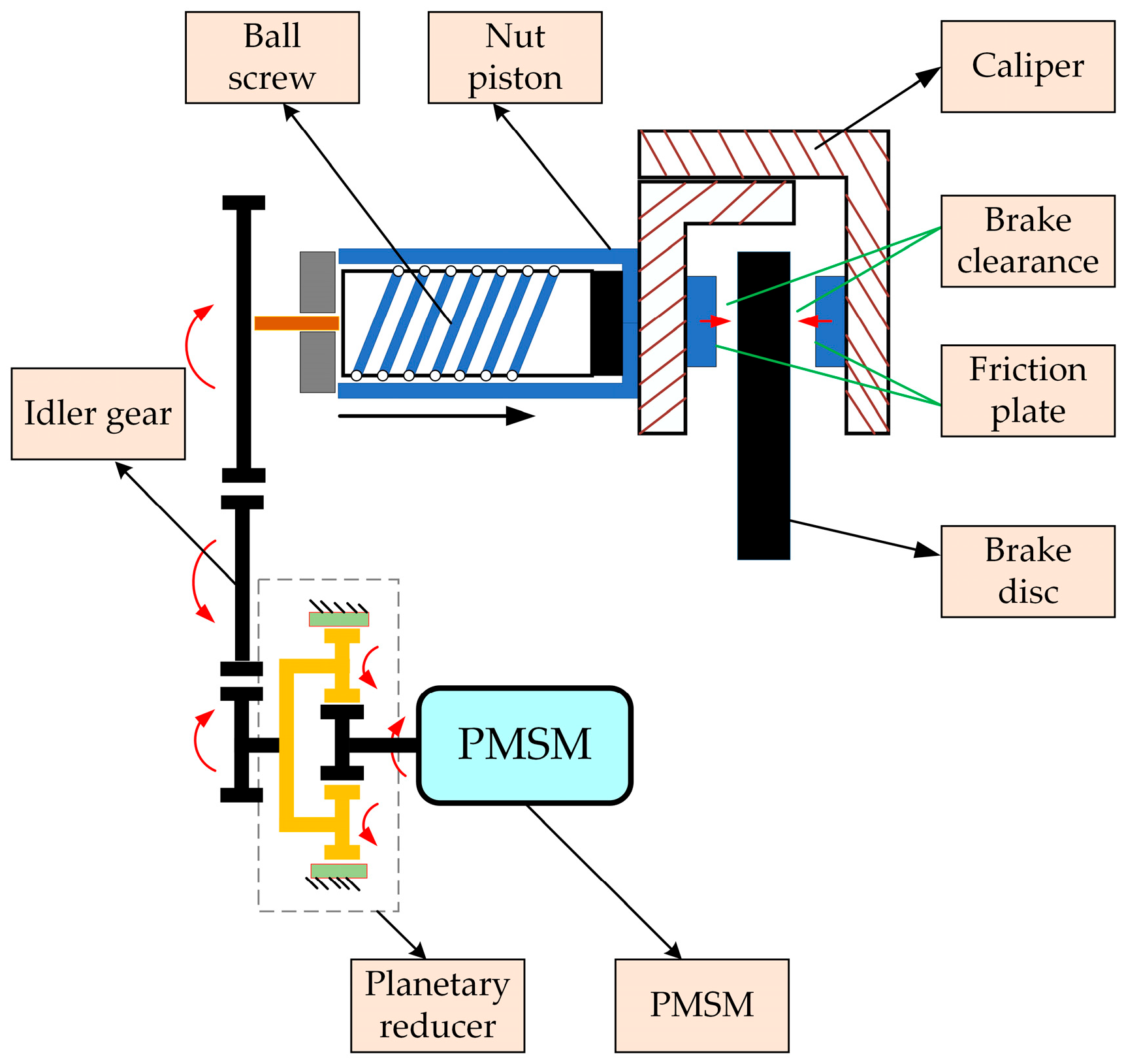
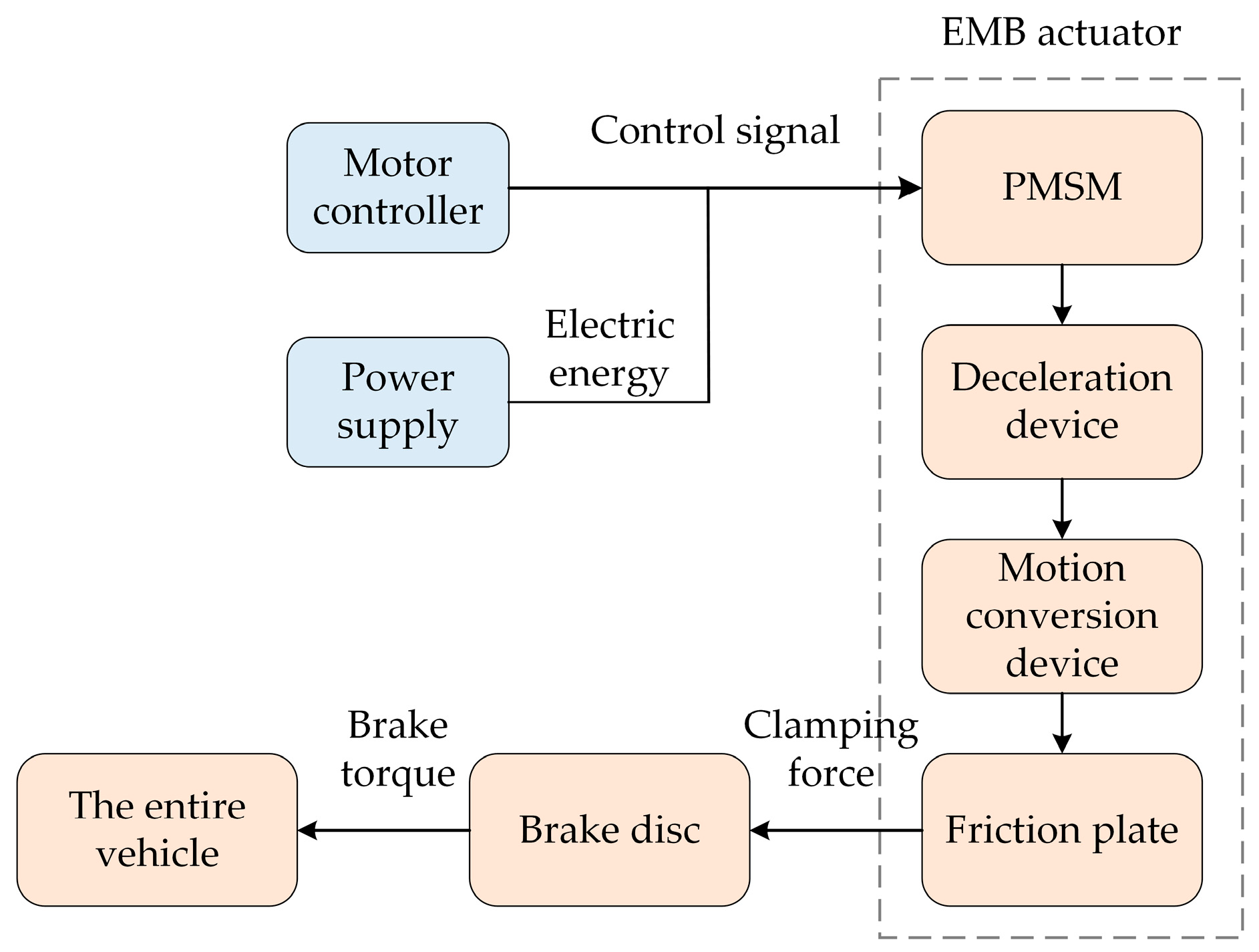
2.1. Composition of the EMB Structure

The main structure of the EMB system consists of brake calipers, brake discs, friction pads, ball screws, planetary gear reducers, motors, motor gears, idler wheels, and secondary reduction gears. The structural diagram is shown in Figure 1.
In the EMB braking system, the brake pedal is completely disconnected from the actuator and in a fully decoupled state. It is connected to the ECU via the CAN bus, and it receives and processes control signals from the ECU through the controller, which enables independent control of the brake clamping force for each wheel. The overall layout is shown in Figure 2.
The working principle of EMB is as follows: When the driver steps on the brake pedal, the displacement and speed of the pedal are converted into electrical signals and input to the ECU. The ECU then issues control instructions to the wheel-side motor controller, which controls the output speed and torque of the motor. First, through the deceleration and torque-increasing device, the output speed of the motor is reduced and the output torque is enhanced. Then, through the motion conversion device, the rotational motion of the motor is converted into axial displacement in the horizontal direction. Since the design in this article directly processes the ball screw nut into the caliper piston, the axial movement of the piston pushes the friction plate, causing it to come into contact with the brake disc and pressurize it, thereby generating braking torque. At this time, the sensor collects the vehicle speed and slip rate as feedback signals and transmits them to the ECU, thereby achieving closed-loop control. The specific structure and working process are shown in Figure 3.
A complete working process of EMB can be divided into three stages. The switching between stages is based on information such as vehicle speed, motor speed, brake clamping force, and pedal displacement obtained by the sensor for judgment and stage switching:
(1)
Clearance Elimination Stage: The motor rotates forward and quickly reaches the set target speed and remains stable, allowing the clearance between the brake disc and the brake friction liner to be eliminated as soon as possible.
(2)
Brake Clamping Force Holding Stage: When the brake disc comes into contact with the friction lining, braking force begins to be generated, as detected by the sensor. The measured displacement of the car’s brake pedal and the pedal speed will be used as parameters to obtain the corresponding brake clamping force, which will be input as the target value into the motor controller. Since the pressure sensor is inconvenient and costly to install in the EMB system, the corresponding brake clamping force is simulated through the ball screw displacement signal. At this point, the motor’s output torque will quickly reach the corresponding set value and remain stable, while the motor is in a locked state.
(3)
Brake Clearance Reset Stage: When the driver releases the brake pedal, in order to ensure the smooth progress of the next brake, the brake clearance needs to be reset quickly. At this time, the motor controller will control the motor to reverse and restore its brake clearance to the original set value.

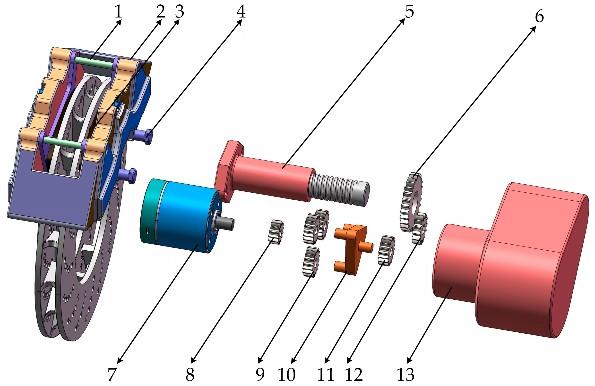
2.2. EMB Actuator Design and Check

2.2.1. Brake Performance Verification

In the design of the brake system, the core parameters mainly include the required braking force, braking clearance, and braking response time. These parameters directly affect the configuration and dynamic characteristics matching of the drive unit, deceleration and torque-increase mechanism, and motion conversion device. The actual braking process of the vehicle is a nonlinear friction behavior [14] under the multi-physical coupling of high torque–high temperature–high pressure strength. To reduce the complexity of the system and achieve quantitative analysis of key parameters, a single-wheel model was used for subsequent research. The single-wheel model of the vehicle is shown in Figure 4.
In this paper, based on the functional equivalence requirements of traditional hydraulic braking systems, the structural parameters of the EMB system are designed for the laboratory prototype. The specific parameters of the target model are shown in Table 1.
The maximum hydraulic oil pressure in the pipeline of the hydraulic disc brake system of this model can reach 12 Mpa, and the diameter of the brake wheel cylinder piston is 50 mm. From this, the maximum clamping force [15] acting on the brake disc is calculated as follows:
F n _ m a x = π × d 2 × P m a x / 4 = 23.56   KN
where F n _ m a x is the maximum clamping force of the caliper, P m a x is the maximum oil pressure in the brake tubing, and d is the diameter of the brake wheel cylinder piston.
In order to ensure the braking reliability of the EMB system, the maximum clamping force of 24 KN is selected in this paper. Based on the relevant parameters of the target vehicle given above, the braking torque T μ and braking force F μ generated on a single wheel can be calculated.
T μ = 2 × F m a x × μ × R = 2030.6   N m
F μ = T μ r = 6.47   KN
where F m a x is the maximum clamping force of the caliper, T μ is the braking torque of the brake, F μ is the braking force of the brake, μ is the friction coefficient of the brake liner, R is the effective radius of the brake disc, and r is the rolling radius of the wheel.
Given that there is an upper limit to ground adhesion, the relationship between the braking force of a single wheel and the ground braking force, ignoring the influence of lateral forces, can be expressed as follows:
F x b = F μ = T μ r F μ F φ F x b = F φ F μ > F φ
F φ = φ × M × g = 14.11   KN
where F φ is the road adhesion, φ is the adhesion coefficient, and F x b is the ground braking force. The maximum ground braking force is equal to the adhesion force. Under full-load conditions, the braking force distribution coefficient at this time can be calculated as follows:
β 0 = φ × h + b L = 0.64
where h is the distance between the center of mass of the vehicle and the ground (0.53 m), L is the wheelbase (2.68 m), and b is the distance from the center of mass to the rear axle (1.25 m); β 0 is the braking force distribution coefficient.
Then, the maximum ground braking force for a single wheel is
F x b _ m a x = F φ × β 0 × 0.5 = 4.52   KN
From Equations (3) and (7), it is known that F μ > F x b _ m a x , i.e., the maximum braking force generated by the EMB actuator exceeds the maximum ground braking force that a single wheel can obtain, which ensures that the vehicle can make full use of the ground friction force regardless of the road surface adhesion conditions, thereby improving the braking performance and safety.
According to the relevant national standards of the Chinese automotive industry (GB7258-2017) [16], when the initial speed of the vehicle is 30 km/h, the braking distance shall not exceed 9 m. At this time, the minimum braking deceleration of the vehicle is
a = V 1 2 V 0 2 2 S = 3.86   m / s 2
where S is the braking distance, V is the initial braking velocity, and a is the braking deceleration.
Assuming that the deceleration of the vehicle during braking is entirely dependent on the sliding friction between the tires and the road surface, the minimum braking force required can be calculated as follows:
F x b _ m i n = M × a = 6.18   KN
From the previous Equations (3), (5) and (9), the following can be obtained:
4 F μ > F φ > F x b _ m i n
From Equation (10) it can be concluded that the maximum braking force provided by the vehicle’s brakes is greater than the maximum braking force on the ground, and the maximum braking force on the ground is greater than the minimum braking force of the vehicle.
The braking clearance on one side of the original hydraulic braking system of this vehicle model was 0.15 mm, and the time to eliminate the braking clearance was 0.24 s. In the EMB system, without changing the original braking clearance S , the braking clearance elimination time is shortened to 0.1 s.

2.2.2. Selection of EMB System Actuator

Due to the high efficiency, high precision, high reliability, and compact lightweight features of ball screws, they meet the core requirements of modern automotive braking for quick response, precise control, and low energy consumption. When the lead of the ball screw increases, its load capacity increases, and its service life and stiffness increase accordingly. However, a larger lead may lead to a decrease in transmission accuracy and an increase in overall size. Since the EMB system is located at the rim or within the hub, the volume requirements for the entire system are more demanding. The size of the ball screw is related to the lead of the screw and the angle of rise of the thread, and it is necessary to minimize the volume of the ball screw as much as possible within the appropriate range. In the EMB workflow, the ball screw is subjected to multiple vibration shocks, so it is necessary to check the rated dynamic load of the ball screw. The initial plan sets the lead of the ball screw to 5 mm.
Based on the provided parameters, the maximum driving torque acting on the screw can be calculated as follows:
T m a x = F m a x × L 0 2 × π × η 1 = 19.67   N m
where F is the maximum brake clamping force, L is the lead of the ball screw, and η 1 is the transmission efficiency of the ball screw.
As can be known from the previous text, the braking clearance is 0.3 mm, and the time to eliminate the braking clearance is approximately 0.1 s. Then, the average rotational speed is 36 rpm. Take two-thirds of the maximum load as the average load for the verification of the rated dynamic load of the ball screw [17]. Selecting two-thirds of the maximum load Fmax as the average load to verify the rated dynamic load of the ball screw uses a constant equivalent average load to approximately simulate the cumulative fatigue damage caused to the screw by the actual variable load conditions (especially including peak loads). Based on engineering experience and life theory, it has been proven that two-thirds of the maximum load Fmax can well represent the actual “average” stress level that lead screws typically endure in many common applications. The verification formula is
C a K h K f K H K n 2 3 F max = 19.3   KN
where K h is the lifespan coefficient of 0.9, K n is the rotational speed coefficient of 0.95, K f is the load factor of 1.5, and K H is the hardness influence coefficient of 0.85.
Planetary gear reducers have a high transmission ratio. Their advantages, such as compact design, high efficiency, and high load-bearing capacity, make them an ideal choice for EMB systems. In order to reduce the output torque requirement of the torque motor and minimize the volume of the torque motor and the planetary gear reducer, a two-stage gear reducer was adopted. When designing the reduction ratio of the gears, the difference in reduction ratio between each stage should not be too large; otherwise, it would cause significant noise and vibration, affecting the power transmission and service life. Initially, the first-stage gear reducer was selected as a planetary gear reducer with a reduction ratio of 4.2; the second-stage reducer was a cylindrical gear reducer with a reduction ratio of 3.54, resulting in a total reduction ratio of 14.868.
The designed EMB system adopts a permanent-magnet synchronous motor as the driving motor. The permanent-magnet synchronous motor has the advantages of high efficiency, high power density, precise control, and excellent locked-rotor performance.
During the process of eliminating the braking clearance, the motor outputs rotational speed and torque, and through the motion conversion device it converts the rotational motion into axial motion, pushing the piston to perform axial displacement. At this time, the motor is approximately in a no-load state. Therefore, the requirement for the elimination time of the braking gap is actually the requirement for the maximum idling speed of the motor:
ω m a x S × i × 60 t × L 0 = 493 r / min
where ω m a x is the maximum rotational speed S is the braking clearance, i is the reduction ratio of the planetary gear reducer, T is the time required for gap elimination, and L 0 the lead of the ball screw.
Since the motor is in a locked-rotor state during braking, it is required that the continuous locked-rotor output torque of the motor satisfy
T d T m a x i = 1.14   N m
where T d is the locked-rotor torque of the motor, while T max is the maximum braking torque of the brake. The relevant parameters of the permanent-magnet synchronous motor are shown in Table 2.
As can be known from the previous text, the maximum rotational speed that the ball screw is subjected to during braking is 36 rpm, the locked-rotor torque that the motor can provide is 1.92 N·m, and the rated rotational speed of the motor is 2000 rpm. The reduction ratio range of the second-order planetary gear reducer can be calculated as follows:
T max T d < i < n e n max
The reduction ratio range of the planetary gear reducer is from 10.3 to 55.5. Considering the installation of the reducer and its volume size, the initially selected reduction ratio of 12.96 in the previous text meets the design requirements.
The relevant parameters of the ball screw and the second-order planetary gear reducer are finally obtained, as shown in Table 3.
Based on the parameter design of the above-mentioned related components, the authors used SolidWorks (https://www.solidworks.com/) to establish the three-dimensional model of the EMB system, as shown in Figure 5, Figure 6 and Figure 7.
This paper adopts a parallel-axis type electric motor dynamic balancing system layout. The output speed and torque of the motor are reduced and increased by a first-stage planetary gear reducer, respectively, and they are then transmitted to the cylindrical reduction gear. After passing through the idler gear, the power is transmitted to the gear connected to the ball screw, and finally, the rotational motion is converted into linear motion through the ball screw, pushing the caliper piston made of the nut to press the friction plate, generating braking force. Compared with the traditional coaxial arrangement of the planetary gear reducer and the ball screw, the axial distance of the traditional electric dynamic balancing system is the sum of the length of the ball screw and the length of the second-stage planetary gear reducer. However, the axial distance of the electric dynamic balancing system designed in this paper is the sum of the length of the screw and the maximum thickness of the gear, which can be shortened by 40% in the direction of the motor shaft, making it more suitable for installation at the hub. The traditional electric dynamic balancing system uses a second-stage planetary gear reducer, while this paper only uses a single-stage planetary gear plus gear transmission. It uses the idler gear for power transmission, so there is a position at the upper end of the cylindrical gear where a PCB board can be placed, thus achieving the integration and encapsulation of the basic braking function of the electric dynamic balancing system and the ABS function. Therefore, the mechanical structure designed in this paper has more advantages.

3. Mathematical Model of the EMB Actuator

3.1. Mathematical Model of Permanent-Magnet Synchronous Motor

Permanent-magnet synchronous motors are a kind of strongly coupled complex nonlinear system, and their precise modeling is quite difficult. Therefore, some reasonable simplifications are usually made during the modeling process:
(1)
Ignore the resistance windings in the motor rotor;
(2)
Ignore the eddy current and hysteresis losses inside the motor and assume that the motor core does not saturate;
(3)
Assume that the three-phase windings of the motor are symmetrically arranged, with an electrical angle difference of 120° between each phase, and the current in the motor presents an ideal three-phase sinusoidal current [18].
Then, the three-phase equations in the natural coordinate system are
U a = R r I a + d ψ a d t U b = R r I b + d ψ b d t U c = R r I c + d ψ c d t
where ψ a , ψ b , and ψ c represent the three-phase stator winding flux linkage of the motor; U a , U b , and U c represent the three-phase voltage of the motor; R r is the three-phase winding resistance of the motor; and I a , I b , and I c represent the phase current of the motor’s three-phase windings.
ψ a ψ b ψ c = L aa M a b M a c M b a L b b M b c M c a M c b L c c I a I b I c + ψ f sin θ e ψ f sin θ e 2 π / 3 ψ f sin θ e + 2 π / 3
where L a a , L b b , and L c c are the self-inductance coefficients of the stator winding; M a b , M a c , M b c , M b a , M c a , and M c b are the mutual inductance coefficients between the stator windings; θ e is the electrical angle difference between the D-axis and the A-phase winding axis in the rotating coordinate system; and ψ f is the magnetic chain of the permanent magnet of the motor’s rotor.
The stator voltage equation of the PMSM obtained in the synchronous selection coordinate system is
U d = R I d + L d d I d d t ω m e L q I q U q = R I q + L q d I q d t + ω m e L d I d + ω m e ψ f
where I d and I q are the current of the d-q axis in the synchronous selection coordinate system, L d and L q are the inductance components of the d-q axis, U d and U q are the voltage of the d-q axis, ω m e is the angular velocity of the motor, and ψ f is a permanent-magnet magnetic chain.
The torque equation of the motor is obtained as follows:
T e = 3 2 p n I q ψ f + L d I d L q I q
where P n is the number of pole pairs of the motor, and T e is the motor torque.
J d ω m d t = T e T l T f
ω m = ω m e p n
where T l is the motor’s load torque, J is the moment of inertia of the motor’s rotor, T f is the frictional torque of the motor, and ω m is the mechanical angular velocity of the motor.
T f = T c + ( T s T c ) exp [ ( v / v S ) δ 1 ] + δ 2 v v 0 T e v = 0 , T e < T s T s sgn ( T e ) v = 0 , T e T s
where T s is the maximum static friction torque (0.0387 N·m), T c is the Coulomb friction torque (0.0192 N·m), T e is the static friction torque of the system, δ 2 is the coefficient of viscous friction (1.086 × 10⁻³), v is the movement speed of the system, v s is the Stribeck speed, and δ 1 is the empirical coefficient. The Stribeck friction model is shown in Figure 8.

3.2. Transmission Mechanism Model

The transmission mechanism of this EMB system consists of a ball screw, a first-stage planetary reduction gear, and a cylindrical reduction gear. The rotational speed and torque generated by the motor are reduced and increased by the reducer, respectively, before being transmitted to the screw of the ball screw, which drives the piston machined by the nut of the ball screw. Through rotation, the nut will undergo axial displacement. Ignoring the axial elastic deformation of the ball screw, the contact between the ball and the raceway is simplified as a linear model; assuming that the stiffness of the gears is idealized and the loads of each planetary gear are evenly distributed, its mathematical model is
s = L θ 2 π i
where L represents the lead of the ball screw, θ is the rotation angle of the motor, i is the reduction ratio of the reducer, and s represents the displacement distance of the nut.

3.3. Drive Motor Load Model

The braking friction force comes from the nut of the ball screw pair driving the piston to push the friction liner, and thus is generated due to the deformation of the friction liner. Chris Line et al. proposed a nonlinear relationship of cubic polynomials that conforms between the braking pressure and the deformation of the friction liner. Based on the measurement results of the physical experiment of the EMB actuator, the polynomial coefficients were obtained through curve fitting [19]. The braking pressure and the deformation of the friction plate adopted in this paper satisfy the following relationship:
F N = 356.767 x 0 x 0.112 1805 x 3 + 27290 x 2 6036 x + 376.2 x > 0.112
x = 0 s s 0 s s 0 s > s 0
where F N represents the braking pressure on one side of the brake, x is the deformation of the friction plate, and s 0 represents the initial distance between the brake friction pad and the brake disc as well as the braking clearance.

3.4. Brake Disc Model

The friction linings on both sides of the brake come into contact with the brake disc and deform, generating a braking torque of T μ . Its mathematical model is
T μ = 2 × F N × R r × f r
where f r represents the friction coefficient between the friction lining and the brake disc, while R r is the effective radius of the brake disc.

4. Design of EMB Segmented Controller

In the three working stages of EMB, corresponding closed-loop control strategies need to be designed according to the different operational requirements of the actuator to achieve the best control effect [20]. During the braking clearance elimination stage, the objective is to rapidly accelerate the motor to the target speed in the shortest possible time and maintain this state to eliminate the braking clearance as soon as possible, thereby enhancing the response speed of braking force control. Therefore, the “rotational speed–current” double closed-loop control strategy was adopted at this stage.
During the brake clamping force holding stage, the motor’s output torque needs to quickly reach and maintain the set value. When the motor’s output torque remains stable, the motor enters a locked-rotor state, and its speed is close to 0. At this time, there is an approximately linear relationship between the motor output torque and the armature current [21]. Therefore, the second-order linear active disturbance rejection controller (LADRC) is adopted to control the motor clamping force, and combined with the PI controller, it is connected in series to obtain the closed-loop control of the “clamping force–current” to achieve precise control of the clamping force.
During the braking clearance reset stage, the aim is to create an initial braking clearance between the braking friction and the brake disc, ensuring the smooth progress of the next braking process. At this stage, the position of the actuator needs to be reset and controlled. The motor reverses to restore the braking clearance to the set initial target value. Therefore, a “position–speed–current” three-closed-loop control strategy is adopted. The control process is shown in Figure 9.

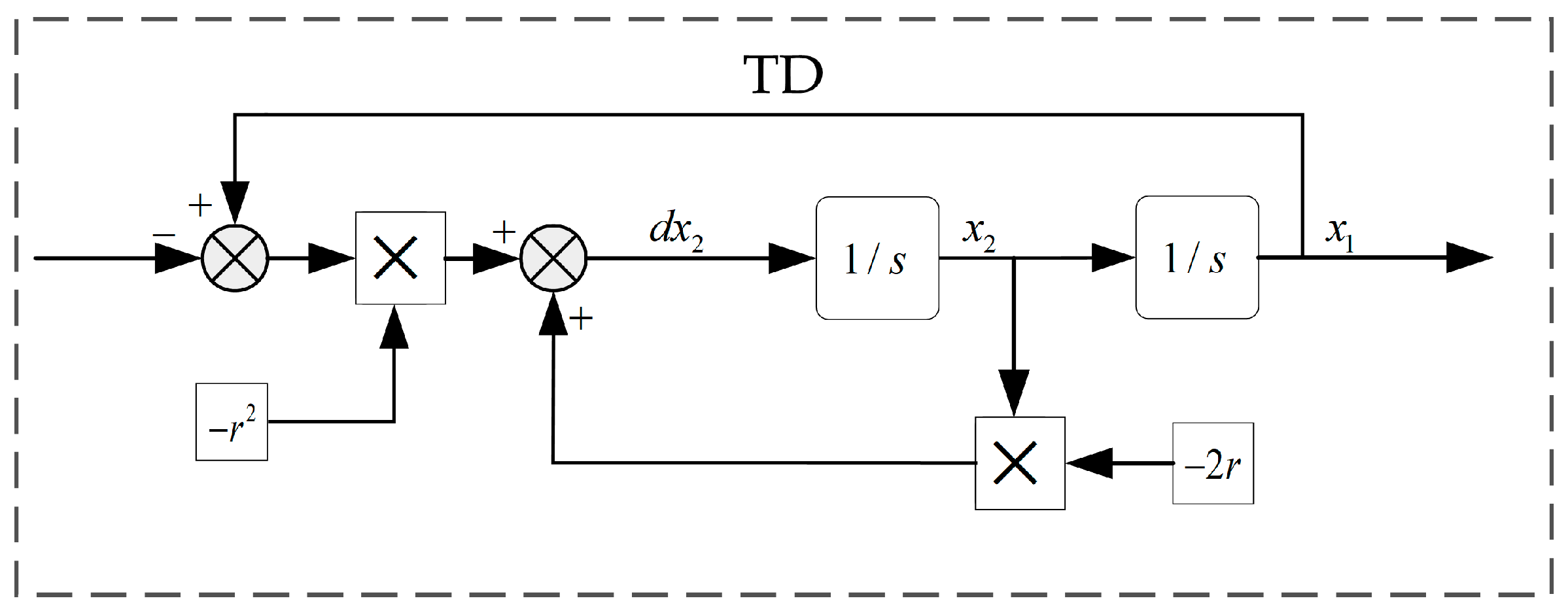
4.1. Controller Design for Braking Clearance Elimination Stage

During the stage of eliminating the braking clearance, the motor needs to be able to increase the rotational speed to the set speed as quickly as possible to eliminate the braking clearance relatively quickly. In the current loop control section, the current consists of the torque current component iq and the excitation current component id, and it is necessary to perform id = 0 control. The most common control strategy for vector control based on PMSMs is control, and at the same time, the intersection current iq is controlled according to the target electromagnetic torque [22]. In this paper, the PI controller is adopted to control the current of the straight axis (D-axis) and the intersection axis (Q-axis):
u ( t ) = K p i e i ( t ) + K i i 0 t e i ( t ) d t
where u represents the control quantity, K p and K i are the proportional term and integral term coefficients of the current loop, respectively, and e is the current control deviation. Configuring the current loop as a typical second-order system to eliminate the steady-state error results in
d I q d t = ( R I q p n ψ f ω m + U q ) L s d ω m d t = 1 J ( 3 2 p n I q ψ f T L )
Then, the state variable of PMSM can be defined as follows:
e 1 = ω r e f ω m e 2 = e ˙ 1 = ω m
where ω r e f is the reference speed of the motor and is a constant, while ω e is the actual rotational speed. From Equations (32) and (33), it can be obtained that
e ˙ 1 = ω ˙ m = 1 J ( 3 2 p n I q ψ f + T L ) e ˙ 2 = ω ¨ m = 3 p n I ˙ q ψ f 2 J
By definition, the equation of state can be obtained as A = 3 p n ψ f / 2 J .
e ˙ 1 e ˙ 2 = 0 1 0 0 x 1 x 2 + 0 A I ˙ q
The proportional integral form of the synovial surface function is defined as follows:
s = c e 1 + e 2
where c is a positive proportionality coefficient, which is used to adjust the sensitivity of the synovial membrane to positional errors. By differentiating Equation (38) and choosing the method of exponential approach law, we can obtain
s ˙ = c e ˙ 1 + e ˙ 2 = c e 2 A I ˙ q s ˙ = ε sgn ( s ) q s
where ε > 0 and q > 0 ; the expression of the controller can be obtained as follows:
I q * = 1 A 0 t [ c e 2 + ε sgn ( s ) + q s ] d t

4.2. Controller Design for Clamping Force Holding Stage

During the braking force holding stage, as the motor is in a locked-rotor state, the actual braking pressure is controlled by regulating the current of the motor. The active disturbance rejection controller (ADRC) is an advanced robust control method based on the integral series architecture design. It consists of the tracking differentiator (TD), the extended state observer (ESO), and the nonlinear state error feedback (NLSEF) [23]. It regards the nonlinear characteristics and external disturbances in the system dynamics as the total disturbance and uses the extended state observer as a means. The implementation estimates the total disturbance and eliminates it. However, due to the introduction of nonlinear functions such as fhan and fal in the nonlinear extended state observer (NLESO) and nonlinear state error feedback (NLSEF), the controller parameters become complex and numerous, and the system stability analysis also becomes more complicated. To solve problems such as the cumbersome parameter adjustment of ADRC, Dr. Gao Zhiqiang proposed a simplified scheme, namely, linear active disturbance rejection control (LADRC). This controller converts the nonlinear functions in NLESO and NLSEF into the linear extended state observer (LESO) and linear error feedback (LSEF) by parameterizing and linearizing them, and it introduces the concept of bandwidth. In this paper, a feedforward second-order linear active disturbance rejection controller is selected to control the clamping force. Since the system can be simplified to a second-order series integral structure, the linear error feedback control rate (LSEF) is replaced by the proportional–derivative (PD) control method. Its basic structural block diagram is shown in Figure 10.
The system friction of the motor load model is regarded as a system disturbance, and the model of the EMB actuator is
F N = f ( x ) + μ x
The EMB pressure control is treated as a second-order nonlinear approximation, as follows:
F ¨ N = f ( x , ω m , i q ) + b 0 i q
where b 0 is
b 0 = μ K T K s J i
where K T is the motor torque coefficient, representing the ratio of the motor’s output torque to the current:
T e = K T i q
If x is selected as the state variable, the tracking differentiator (TD) can be obtained as follows:
v 2 = v ˙ 1 v ˙ 2 = r 2 ( v 1 r ) 2 r v 2
where r is the tracking factor, which is used to adjust the tracking speed of the reference signal and the smoothness of the tracking speed. Take v 1 as the smoothed reference signal to replace the original input and avoid sudden shocks, and take v 2 as the differential of the reference signal, enhancing the dynamic response of the controller. Its structure is shown in Figure 11 as follows:
The third-order extended equation of state is obtained as follows:
x ˙ 1 = x 2 x ˙ 2 = x 3 + b 0 i q x ˙ 3 = f ˙ F N = x 1
where x 1 represents the observed value of the brake clamping force, x 2 represents the first-order differential observed value of the brake clamping force, and x 3 represents the expanded state observed quantity. The third-order LESO for the clamping force control of EMB is established as follows:
z ˙ 1 = z ˙ 2 e β 1 z ˙ 2 = z 3 e β 2 + b 0 i q z ˙ 3 = e β 3 e = z 1 F N
where β 1 , β 2 , and β 3 represent the observer error feedback gain. To simplify the design, it is expressed using the observer bandwidth ω 0 , which can be expressed as follows:
β 1 = 3 ω 0 β 2 = 3 ω 0 2 β 3 = ω 0 3
Its structure is shown in Figure 12.
The feedback control adopted by PD control is
u 0 = k P F N * z 1 k D z 2
where k p and k d represent the observer state feedback gains, which can be expressed as follows:
k P = ω c 2 k D = 2 ω c
When the motor is in a locked state, the brake clamping force is linearly related to the motor’s output torque, and the motor’s output torque is directly proportional to the armature current. Therefore, the deviation between the target clamping force and the actual clamping force can be selected as the feedforward term for control. The specific expression is as follows:
i q = K s F N i K T
The feedforward control quantity is
i q f * = K s F N * z 1 i K T
The final brake clamping force control target can be obtained as follows:
i q * = u 0 z 3 b 0 + i q *

4.3. Stage Judgment and Switching Design

The braking stage is judged based on the actual vehicle speed, the target brake clamping force, and the actual brake clamping force. When the vehicle speed is not equal to zero and the actual clamping force is zero, it is in the stage of eliminating the braking clearance at this time. When the braking clearance is eliminated, the clamping force begins to be generated at this time, with a value greater than zero and the vehicle speed also greater than zero. At this point, it is in the braking force holding stage, and it is necessary to quickly reach the target braking force and maintain it continuously. When the vehicle speed decelerates to zero and the braking force is greater than zero, it is in the stage of resetting the braking clearance at this time. Under the switching of control strategies in three stages, they jointly constitute the EMB multi-stage closed-loop control strategy.

5. EMB Simulation Analysis

5.1. Analysis of Motor Speed and Position Control

In order to verify the effectiveness of the SMC controller in speed tracking control and the performance of the three-closed-loop PID series control in motor position tracking control, a speed loop simulation experiment was conducted. The experimental results are shown in Figure 13 and Figure 14.
For the motor speed control loop, in the sin signal tracking control, the SMC controller can achieve a lag time of only 3 ms and an overshoot of only 0.02%; in the step signal tracking control, the SMC controller can achieve a maximum lag time of 40 ms and a maximum overshoot of 0.05%. It can be seen that the tracking effect is excellent, and it can reach the set speed value at the fastest speed and remain stable; that is, it can eliminate the braking gap at the fastest speed.
For the motor position loop control, in the step signal tracking control, the three-loop PID controller can achieve a lag time of only 10 ms and an overshoot of only 0.01%; in the triangular signal tracking control, the three-loop PID controller can achieve a maximum lag time of up to 60 ms and a maximum overshoot of 0.02%. It can be seen that the motor position tracking effect is excellent, and it can reach the set motor position at the fastest speed and remain stable; that is, it can restore the braking gap at the fastest speed and remain stable.

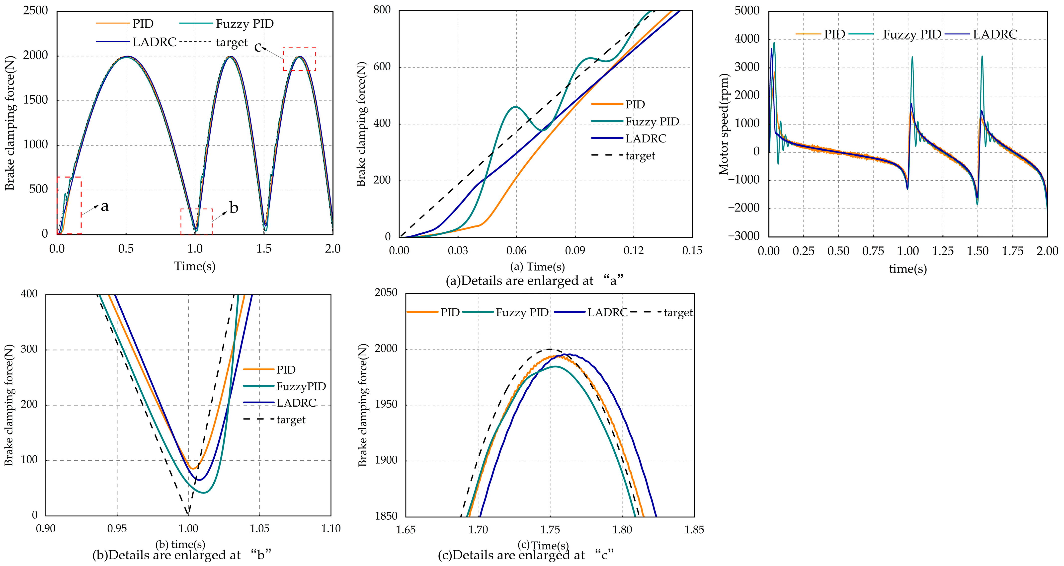
5.2. Force Following Control Analysis

In order to verify the anti-interference capability of the LADRC controller in controlling the clamping force, a simulation experiment was conducted on the clamping force loop. The experimental results are shown in Figure 15.
The control target value of the clamping force is 5000 newtons. Under the condition that the overshoot is almost the same, the LADRC controller reaches the steady state at 0.18 s, while the PID controller reaches the steady state at 0.3 s. The LADRC controller reaches the steady state at 0.18 s, and the optimization effect can reach 40. When a step load is added to the motor at 0.1 s, the LADRC controller reduces the movement of the PID controller by 41.2%, which shows that the LADRC controller has stronger anti-interference ability.
In addition, the continuous step condition and the triangular signal condition were simulated. The simulation experiment results of the clamping force and the corresponding rotational speed are shown in Figure 16 and Figure 17.
Under the continuous step condition, as shown in Figure 16a, while maintaining a similar time for reaching the target value, the overshoot of the fuzzy PID controller reaches 10.85%, while that of the LADRC controller is less than 1%. The optimization effect on the overshoot of the LADRC controller is approximately 90%, whereas traditional PID control has a delay of up to 0.12 s, and both the PID and fuzzy PID controllers exhibit vibration in subsequent control. The difference can also be observed through the comparison of rotational speeds. Similarly, in Figure 16b,c, the following effect for the step signal can be clearly seen: the overall effect of the LADRC controller is much better than that of traditional PID control and fuzzy PID control.
Under the triangular signal tracking condition, with almost the same overshoot, the fuzzy PID control has a larger fluctuation, and both it and the traditional PID control reach the steady state only after 0.25 s. However, the LADRC reaches the steady state at approximately 0.01 s, reducing the response time by 240 ms. At 2 s, the tracking quantity of the LADRC controller can reach the minimum value of 5 N, which is 50% less than the minimum tracking quantity of 10 N for the fuzzy PID control and 46 N for the traditional PID control. Moreover, it can be observed from the speed of the coriander motor that the LADRC controller enables the motor to reach a higher speed and remain stable faster than the fuzzy PID control and the traditional PID control.
To further verify the tracking effect of the LADRC controller on the clamping force, a special subsequent clamping force condition was simulated. The simulation experiment results are shown in Figure 18.
Under the condition of similar steady-state error, the LADRC controller can reach the stable state more quickly, and during the control process, the vibration amplitude is significantly better than that of the traditional PID controller and the fuzzy PID controller. Through the simulation tests of the above three different working conditions, it can be seen that the LADRC controller has the best overall performance in terms of tracking control, response speed, steady-state error, and anti-interference ability.

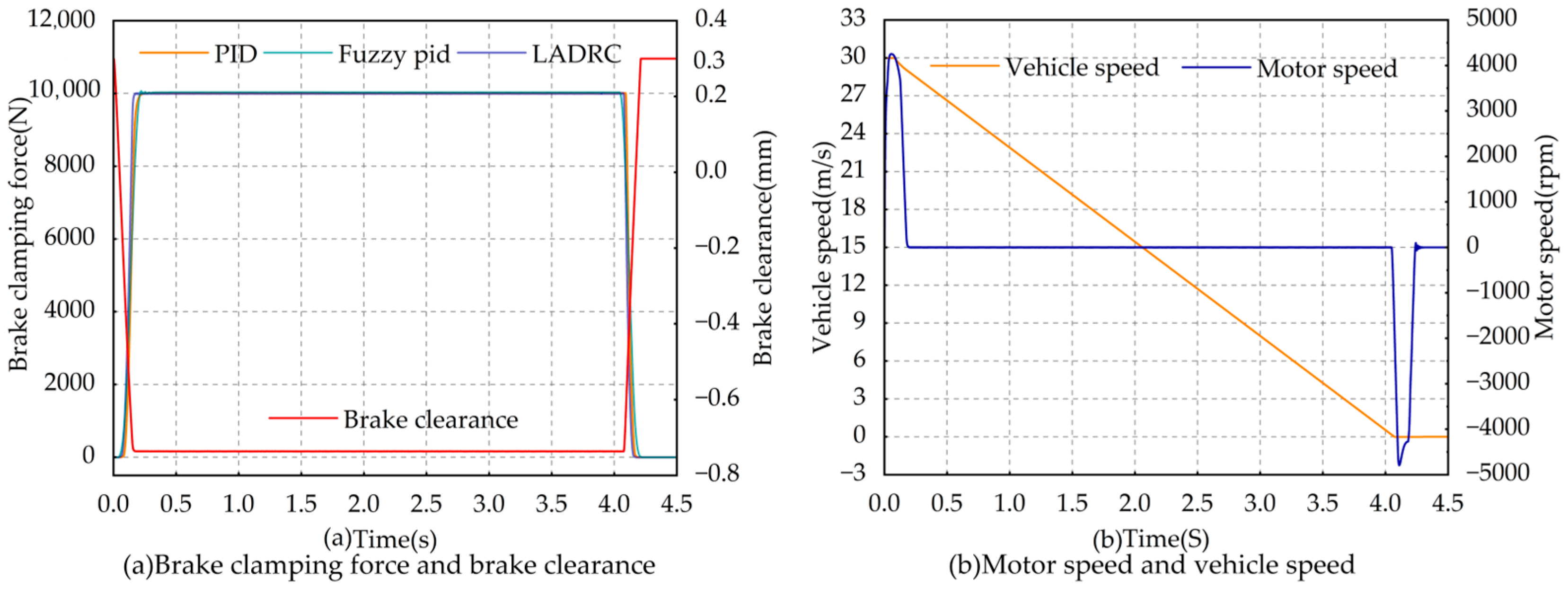
5.3. Analysis of Emergency Braking Conditions

In order to verify the effectiveness of the segmented closed-loop control strategy designed in this paper, an emergency braking condition simulation test was conducted. The simulation model diagram is shown in Figure 19. The initial vehicle speed was set at 108 km/h. After receiving the braking command, it was in the braking elimination stage first. The motor carried out speed loop tracking control through the SMC control algorithm. Then, when the braking gap was eliminated, this was the braking clamping force maintenance stage. The motor achieved the target clamping force quickly through the LADRC control algorithm and maintained stability until the vehicle speed dropped to 0. At this point, the motor was controlled by the PID controller to restore the braking gap. Thus, the emergency braking was completed.
The simulation test results are shown in Figure 20. It can be seen that regardless of which control algorithm is used, the clamping force ring can complete the emergency braking condition. However, in terms of the response time to reach the steady state, the LADRC control algorithm is 50 ms earlier than the other two algorithms. Three-stage control enables the motor speed to quickly reach the set value, the clamping force to remain stable, and finally allows for the recovery of the braking gap, thereby verifying the rationality of the three-stage control.

5.4. EMB Hardware-In-the-Loop Test Bench Verification

To verify the feasibility of the clamping force control strategy proposed in this paper in engineering applications, an experimental platform, as shown in Figure 21, was built, and relevant verification experiments were conducted.
The experimental bench pedal simulator, PCBA control board, EMB actuator, and circuit box are composed of each other. The photos are shown in Figure 22a–d, respectively.
The algorithm of the feedforward second-order linear active disturbance rejection controller based on clamping force, as mentioned in this article, was burned into the controller. An EMB hardware-in-the-loop clamping force tracking control experiment was conducted, and the results shown in Figure 23 were obtained.
The EMB hardware-in-the-loop test bench uses a pedal simulator to output the target braking clamping force. Through a travel sensor and previous calibration data, the target braking clamping force of the caliper is output. Signal transmission is carried out via CAN and controlled by the PCB board to control the movement of the EMB actuator and output the target braking clamping force. The opening degree of the brake pedal is shown in Figure 23a, the target clamping force of the left rear wheel and the right rear wheel is shown in Figure 23b, and the actual clamping force of the left rear wheel and the right rear wheel is shown in Figure 23c.
From the experimental data graph, it can be seen that different pedal openings correspond to different target clamping forces. In the tracking control of the target clamping force, the second-order linear active disturbance rejection control algorithm proposed in this paper can achieve a maximum overshoot of 1%, with a response tracking delay of less than 50 ms and a very small steady-state fluctuation. Therefore, it can be proven that the control algorithm proposed in this paper has practical application value.

6. Conclusions

This paper designed and analyzed an EMB system for passenger vehicles. In terms of structural layout, a different-axis arrangement of the motor, the first-stage reducer, and the motion conversion device was proposed, and the PCB board of the wheel-side controller was placed inside the EMB housing for integration. In terms of control strategy, the mathematical models of each mechanism were determined based on the physical structure of the EMB system, and a feedforward second-order linear active disturbance rejection control algorithm based on clamping force and a judgment process for the braking stage were proposed. Through simulation experiments and the EMB hardware-in-the-loop test bench, the following conclusions were drawn:
(1)
By adopting a layout where the motor and the ball screw are not on the same axis, the length of the traditional coaxial EMB system can be reduced by 30% in the axial distance of the motor. This is more conducive to the layout of the EMB system at the vehicle’s wheel hub. Moreover, through the design of the housing, the PCB board can be integrated into the EMB housing, allowing the basic locking release function of EMB, the ABS function, and the ESP function to be integrated. This can reduce the information transmission time and enhance the active safety performance of the vehicle.
(2)
A feedforward second-order linear active interference suppression control algorithm based on braking clamping force was proposed. Compared with the traditional PID control, its anti-interference ability is improved by approximately 41.2%; in the clamping force tracking control, its overshoot is approximately 9.85% lower than that of the adaptive fuzzy PID control; in terms of the time to reach the steady state, it is approximately 130 ms earlier compared to the other two control algorithms, and at the steady state, the fluctuation is smaller; after optimizing the braking force response, the braking efficiency and stability are improved. Through simulation experiments, the rationality of the segmented control planning was verified. This enables the completion of the braking process and the adaptation of the brake pedal.
(3)
Through the EMB hardware-in-the-loop test bench, it can be seen that in terms of the clamping force tracking control, the response delay is only 70 ms, and the overshoot is less than 1%. This is essentially consistent with the simulation test results. It can be seen that the proposed braking clamping force tracking control algorithm is reasonable and effective, and it can improve the braking safety of the vehicle.
Since this paper only used a single-round model for verification, many assumptions and omissions were made for the complex nonlinear system of the motor, as well as the assumption that other transmission mechanisms are rigid during the transmission process. Therefore, this research has limitations. Our next research focus will be on the vehicle’s EMB, integrating ABS and ESP functions, conducting more in-depth research on longitudinal dynamics, and analyzing the failure of four-wheel independent braking. Finally, real vehicle experiments will be conducted for verification.

Author Contributions

Conceptualization, writing—original draft preparation, J.Z.; methodology, visualization, resources, investigation, software, H.Y.; supervision, Y.Y.; data curation, writing—review and editing, supervision, X.H. All authors have read and agreed to the published version of the manuscript.

Funding

This research was funded by the Project of National Natural Science Foundation of China (52202480) and the Project of Natural Science Foundation of Hubei Province (2022CFB732).

Data Availability Statement

The original contributions presented in this study are included in the article. Further inquiries can be directed to the corresponding author.

Conflicts of Interest

The authors declare no conflicts of interest.

References

  1. Paul, D.; Velenis, E.; Cao, D.; Dobo, T. Optimal μ-estimation-based regenerative braking strategy for an AWD HEV. IEEE Trans. Transport. Electrific. 2017, 3, 249–258. [Google Scholar] [CrossRef]
  2. Hu, M.; Li, J.; Bian, Y. Distributed Coordinated Brake Control for Longitudinal Collision Avoidance of Multiple Connected Automated Vehicles. IEEE Trans. Intell. Veh. 2022, 8, 2567–2581. [Google Scholar] [CrossRef]
  3. Zhang, Y.; Chen, L.; Wang, H. Adaptive Braking Torque Control for Electronic Mechanical Brake Systems Based on Real-Time Axle Load Observation. IEEE Trans. Intell. Veh. 2023, 4, 567–582. [Google Scholar]
  4. Bai, F.H.; Zhang, Q.; Guo, J.J. Research on the Control Strategy of Bending Road Braking Force for Electro-mechanical Brake Based on Active Disturbance Rejection Control. Automob. Technol. 2023, 6, 55–62. [Google Scholar]
  5. Mu, X.D. The Dynamic Control System for Electronic Mechanical Braking Control Strategy Research. Master’s Thesis, Jilin University, Changchun, China, 2021. [Google Scholar]
  6. Park, G.; Choi, S.; Hyun, D. Clamping force estimation based on hysteresis modeling for electro-mechanical brakes. Int. J. Automot. Technol. 2017, 18, 883–890. [Google Scholar] [CrossRef]
  7. Wei, Z.; Xu, J.; Halim, D. Clamping force control of Sensor-less Electro-Mechanical brake actuator. In Proceedings of the 2017 IEEE International Conference on Mechatronics and Automation (ICMA), Takamatsu, Japan, 6–9 August 2017; pp. 764–769. [Google Scholar]
  8. Fu, Y.F.; Hu, X.H.; Wang, W.R. Simulation and Experimental Study of a New Electromechanical Brake with Automatic Wear Adjustment Function. Int. J. Automot. Technol. 2020, 21, 227–238. [Google Scholar] [CrossRef]
  9. Li, J.; Mengchun, W.; He, R. A design of electromechanical brake system triple-loop controllers using frequency domain method based on Bode plote. In Proceedings of the 2011 International Conference on Transportation, Mechanical, and Electrical Engineering (TMEE), Changchun, China, 16–18 December 2011; pp. 795–798. [Google Scholar]
  10. Fox, J.; Roberts, R.; Baier-Welt, C. Modeling and control of a single motor electronic wedge brake. SAE Trans. 2007, 116, 321–331. [Google Scholar]
  11. Peng, X.; Chen, C.; Zhang, J. Study of the sliding mode control of electromechanical brake systems. Hunan Univ. (Nat. Sci.) 2010, 37, 35–39. [Google Scholar]
  12. Line, C.; Manzie, C.; Good, M.C. Electromechanical brake modeling and control: From PI to MPC. IEEE Trans. Control Syst. Technol. 2008, 16, 446–457. [Google Scholar] [CrossRef]
  13. Lee, C.F.; Line, C.M.C. Explicit nonlinear MPC of an automotive electromechanical brake. IFAC Proc. Vol. 2008, 41, 10758–10763. [Google Scholar] [CrossRef]
  14. Liu, Z.Q.; Wang, Z.; Chen, Y.J. Modeling, Simulation and Experimental Research of Electro-Mechanical Brake. Mech. Electr. Eng. 2023, 40, 485–493. [Google Scholar]
  15. Wang, Z. Electronic Mechanical Braking System Control Strategy Design and Simulation Study. Master's Thesis, Jiangsu University, Zhenjiang, China, 2023. [Google Scholar]
  16. GB7258-2017; Technical specifications for safety of power-driven vehicles operating on roads. China Standard Press: Beijing, China, 2017.
  17. Huang, Y.J. Selection Calculation and Application of Ball Screw Pair. Metalworking 2011, 19, 46–48. [Google Scholar]
  18. Yuan, L.; Hu, B.X.; Wei, K. Control Principle of Modern Permanent Magnet Synchronous Motor and MATLAB Simulation; Beihang University Press: Beijing, China, 2016. [Google Scholar]
  19. Jia, M.F. Research on Control Strategy of Automotive Line Control Actuator. Master's Thesis, Hunan University, Changsha, China, 2018. [Google Scholar]
  20. Song, Y.D.; Hao, M.J.; Yu, B.W. Electronic mechanical brake phases closed-loop control strategy research. Shandong Univ. Sci. Technol. (Nat. Sci. Ed.) 2024, 38, 1–6. [Google Scholar]
  21. Liu, Y.G. Research on ABS Control of Automotive Electronic Mechanical Braking System Based on Active Disturbance Rejection Control. Master's Thesis, Jiangsu University, Zhenjiang, China, 2023. [Google Scholar]
  22. Zhou, Y.Y. Automobile Electronic Mechanical Braking System Control Strategy Research. Master's Thesis, Chang’an university, Xi’An, China, 2022. [Google Scholar]
  23. Ma, L.Y.; Wang, Y.; Ma, J. Parameter tuning of second-order Linear active disturbance rejection control based on PI parameters. Control Eng. 2024, 31, 1761–1767. [Google Scholar]
Figure 1. Diagram of the EMB structure.
Modelling 06 00072 g001
Figure 2. The layout of EMB in the entire vehicle: 1. EMB actuator; 2. CAN bus; 3. control circuit; 4. brake system controller; 5. brake pedal; 6. power supply.
Modelling 06 00072 g002
Figure 3. EMB work process.
Modelling 06 00072 g003
Figure 4. Single-wheel model of the car.
Modelling 06 00072 g004
Figure 5. 3D explosion view of the EMB actuator: 1. guide rod; 2. caliper; 3. friction plate; 4. screw bolt; 5. ball screw (clamp piston); 6. second-stage reduction-driven wheel; 7. PMSM; 8. motor gear; 9. planetary gear; 10. planetary gear; 11. secondary reduction driving wheel; 12. idler gear; 13. shell.
Modelling 06 00072 g005
Figure 6. Upper view of the EMB actuator.
Modelling 06 00072 g006
Figure 7. Front view of the MB actuator.
Modelling 06 00072 g007
Figure 8. Stribeck friction model.
Modelling 06 00072 g008
Figure 9. Segmented control strategy.
Modelling 06 00072 g009
Figure 10. Feedforward second-order linear active disturbance rejection controller.
Modelling 06 00072 g010
Figure 11. Tracking the structure of the differentiator.
Modelling 06 00072 g011
Figure 12. Third-order linear extended state observer.
Modelling 06 00072 g012
Figure 13. Continuous step and sinusoidal signal speed tracking of different frequencies.
Modelling 06 00072 g013
Figure 14. Step signal and triangular signal motor position tracking control.
Modelling 06 00072 g014
Figure 15. Interference signal-based clamping force tracking control.
Modelling 06 00072 g015
Figure 16. Comparison of clamping force for step signals and comparison of rotational speed.
Modelling 06 00072 g016
Figure 17. Tracking and comparison of triangular signal clamping force.
Modelling 06 00072 g017
Figure 18. Sin signal clamping force tracking control.
Modelling 06 00072 g018
Figure 19. Segmented control simulation diagram.
Modelling 06 00072 g019
Figure 20. Simulation comparative analysis of emergency braking conditions.
Modelling 06 00072 g020
Figure 21. EMB hardware-in-circuit test bench.
Modelling 06 00072 g021
Figure 22. All components of the test bench.
Modelling 06 00072 g022
Figure 23. Brake pedal opening, target clamping force, and actual clamping force.
Modelling 06 00072 g023
Table 1. Parameters related to the target vehicle.
Parameter Name/Unit
Vehicle full-load mass M/kg1600
Wheel rolling radius r/m0.314
Effective radius of the brake disc R/m0.132
Friction coefficient of brake lining μ0.32
Pavement adhesion coefficient φ0.86
Gravitational acceleration g/(m/s2)9.8
Centroid height h/m0.53
The distance between the center of mass and the rear axis b/m1.25
Automobile wheelbase L/m2.68
Table 2. Relevant parameters of PMSM.
NameParameter/UnitNumerical Value
PMSMRated power  P e /w200
Rated speed of the motor  ω e /rpm6000
Motor locked-rotor torque  T d /Nm1.92
Motor torque coefficient  K /N·m/A0.13
Rated voltage of the motor  V e /V12
Motor pole logarithm  P n 4
Table 3. Parameters related to the actuators of the EMB system.
NameParameter/UnitNumerical Value
Ball screwLead L/mm5
Thread elevation angle °15
Transmission efficiency  η 1 0.97
Planetary gear reducerReduction ratio  i 12.96
Moment of inertia J/kg·cm20.03
Transmission efficiency  η 2 0.94
Disclaimer/Publisher’s Note: The statements, opinions and data contained in all publications are solely those of the individual author(s) and contributor(s) and not of MDPI and/or the editor(s). MDPI and/or the editor(s) disclaim responsibility for any injury to people or property resulting from any ideas, methods, instructions or products referred to in the content.

