Article

Dynamic Modelling and Simulation of a Permanent Magnet Synchronous Motor (PMSM) Applied in a Prototype Race Car and the Comparison of Its Performance with BLDC Motor

by
Attila Szántó
1,*,
Masuk Abdullah
2,
Tibor Péter Kapusi
3 and
Szabolcs Sándor Diós
4
1
Department of Basic Technical Studies, Faculty of Engineering, University of Debrecen, Ótemető Str. 2-4, H-4028 Debrecen, Hungary
2
Department of Vehicles Engineering, Faculty of Engineering, University of Debrecen, Ótemető Str. 2-4, H-4028 Debrecen, Hungary
3
Department of Data Science and Visualization, Faculty of Informatics, University of Debrecen, Kassai Str. 26, H-4028 Debrecen, Hungary
4
Faculty of Informatics, Debrecen University, H-4032 Debrecen, Hungary
*
Author to whom correspondence should be addressed.
Modelling 2025, 6(3), 104; https://doi.org/10.3390/modelling6030104
Submission received: 24 July 2025 / Revised: 12 September 2025 / Accepted: 15 September 2025 / Published: 16 September 2025

Abstract

Electric vehicles are playing an important role in transport, aided by rapid advances in battery technology. The Faculty of Engineering at the University of Debrecen is also engaged research and development in the field of electric vehicles. To support the development of electric vehicle prototypes, a vehicle dynamics simulation program has been designed. The study presents the modeling and simulation of a permanent magnet synchronous motor (PMSM) in MATLAB/Simulink, which has been integrated into the existing vehicle dynamics simulation framework. The methods used to determine the motor characteristics required for the simulation are described in detail. In addition, the performance of the PMSM is compared with that of a brushless DC (BLDC) motor within the vehicle dynamics simulation program. The developed method allows the selection of the appropriate motor type for the given competition tasks.

1. Introduction

Electric vehicles are playing an increasingly important role in road transport today, thanks to the rapid development of modern batteries and electric systems. In addition, a number of other factors are also influencing this trend, such as increasing environmental awareness and the resulting legal regulations, or economic considerations, as more and more manufacturers are now offering a viable alternative to conventional internal combustion engine vehicles in the field of electric vehicles. This means that the entire global vehicle industry is currently undergoing a transformation. One of the main components of hybrid and electric vehicles is the electric motor, for which manufacturers use a variety of different types of motors to power their vehicles [1,2,3]. These motor types are summarized in Figure 1 [1].
Each type of motor has different characteristics, so when designing a new vehicle, for example, these must be taken into account in order to select the optimum motor for the vehicle. The selection process usually starts with vehicle dynamics simulations [4], the results of which can provide a good basis for the decision. The above facts underline the importance of research into different types of electric motors.
The Faculty of Engineering of the University of Debrecen has more than a decade of experience in the development of pneumatic and electric prototype race cars. In order to improve the efficiency and awareness of development and racing, a vehicle dynamics simulation program has already been developed [4]. One element of the above program is the simulation of the electric motor, which has been previously performed for brushless DC (BLDC) and series-wound DC (SWDC) motors and incorporated into the vehicle dynamics simulation program [5]. Since the permanent magnet synchronous motor (PMSM) is often used in electric drive vehicles due to its outstanding properties, in this paper, the model and simulation program of this motor are presented in MATLAB/Simulink (R2022b) and applied to the above vehicle dynamics simulation program. In order to run the simulation program, it is necessary to know the various electromagnetic and dynamic characteristics of the motor, which are often not or only partially provided by the manufacturers. Therefore, methods developed for the experimental determination of the motor characteristics required as input to the simulation program are also presented. Furthermore, the research compare the performance of the PMSM motor with another motor type (BLDC) in the vehicle dynamics simulation program to select the optimal motor type for the competition tasks. The results obtained here may be useful for the design of a Formula Student race car in the future.
Although there are several publications in the literature dealing with the modelling and simulation of PMSM motors [6,7,8,9,10,11] or the experimental determination or estimation of the motor characteristics [12,13,14], no comprehensive publication on the above has been found. In this research, after a detailed description of the motor model and simulation, used this motor simulation as a module of a vehicle dynamics simulation program and run it with different type of motors to compare and analyze the results obtained. In addition, present research provide a comprehensive solution for the experimental determination of engine characteristics, building upon extensive prior experience in this field [15,16,17,18], which is also novel in the literature.

2. The Applied Vehicle Dynamics Simulation Program

The following section briefly presents a vehicle dynamics simulation program previously developed for prototype race cars in a MATLAB Simulink environment [4]. One of the modules of the program is the simulation of an electric motor, which has been previously implemented and tested for two types of motors (BLDC, SWDC) [5]. In connection with this, in the following sections, present the modelling and simulate the PMSM motor and integrate it into the vehicle dynamics simulation program. In this way, simulation results for different motor types can be compared.
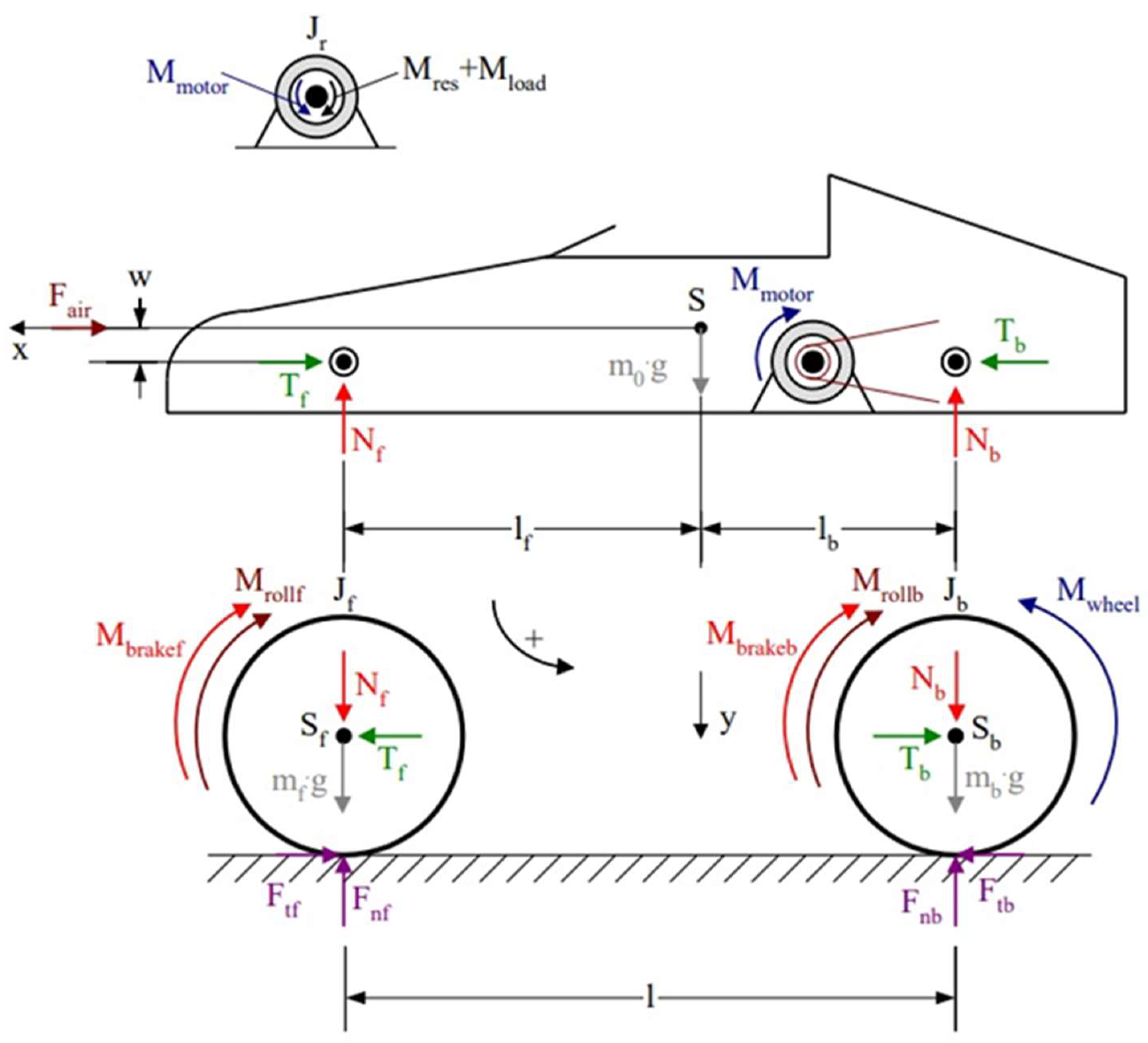
The simulation program mentioned above is based on a proprietary vehicle dynamics model, the structure of which is shown in Figure 2.
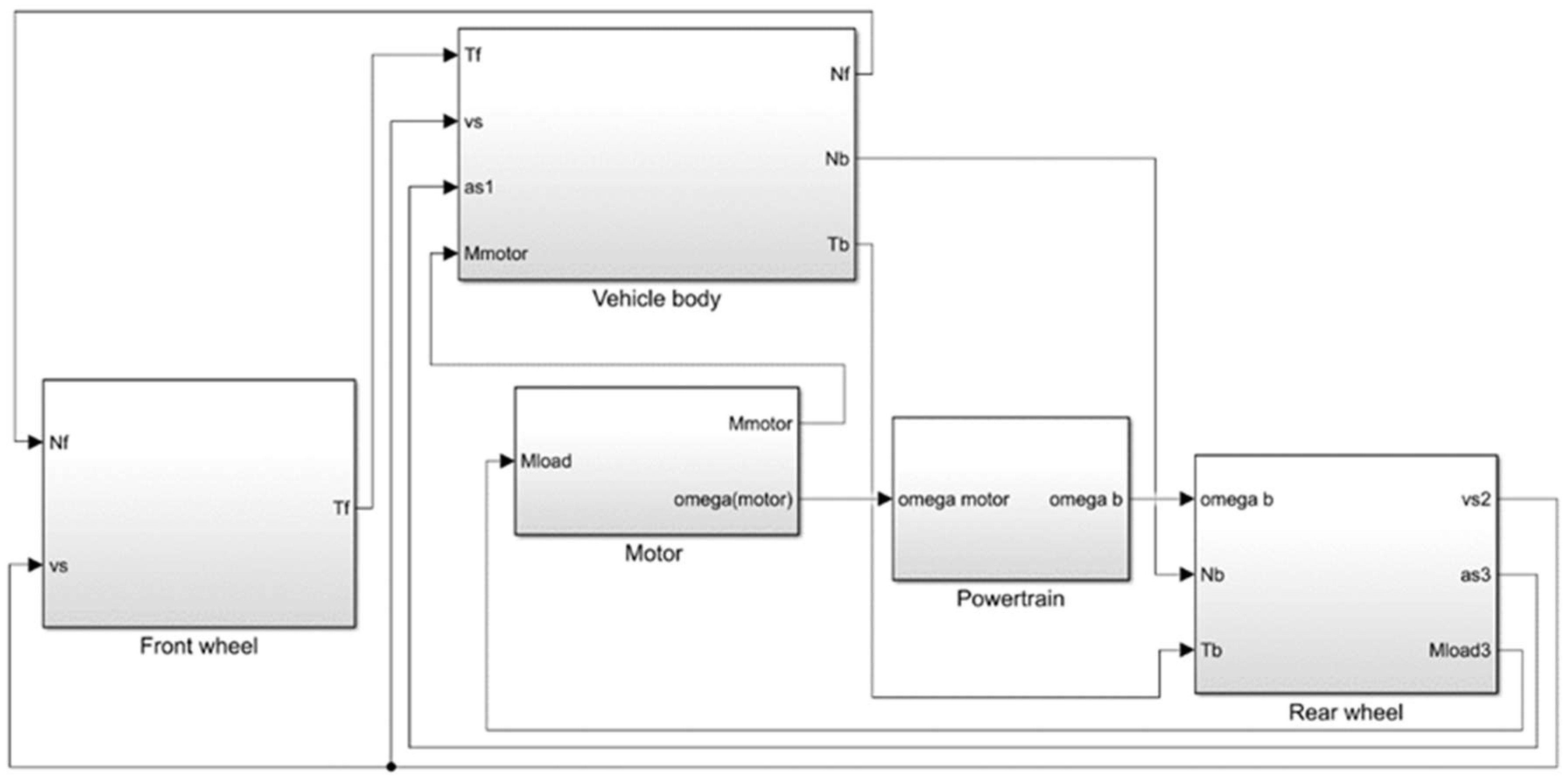
The model was developed for an electric single-seater prototype race car, with a sufficiently rigid frame and chassis, and powered by an electric motor that drives the rear wheels via a chain drive. In the model, the vehicle is divided the vehicle into 4 structural units, which are the vehicle body, including the motor housing (stator), the rotor of the motor, the freely rotating front and the driven rear wheels with the rotating parts belonging to them. A description of the meaning of the symbols shown in Figure 2 can be found in [4]. Based on the models presented in Figure 2, a vehicle dynamics simulation program in MATLAB Simulink (R2022b) [4] was created. The modular structure of the simulation program is shown in Figure 3.
The simulation program, in accordance with the above dynamic model, is built up of five modules: vehicle body, front wheels and related rotating machine parts, rear wheels and related rotating machine parts, motor and powertrain. A detailed description of the structure and operation of the different modules of the program can be found in reference [4]. For the purpose of this publication, the “Motor” simulation module shown in Figure 3 is important, as the PMSM motor simulation module developed in Section 3 can be installed in its place. The input to this module is the load torque (Mload) exerted by the vehicle, as well as the electromagnetic and dynamic characteristics of the motor (see Section 3), while its output is the torque delivered by the motor (Mmotor) and the motor angular velocity (omega(motor)). So, the motor simulation module is connected to the vehicle dynamics simulation program through these inputs and outputs.
The inputs of the whole simulation program and its output functions are also found in [4]. The input parameters of the simulation program are mainly the technical data and characteristics of the vehicle and motor. Some of the above data can be found in the catalogue of the motor and other machine parts, or in the related scientific literature, but in most cases, they must be determined experimentally [15,16,17,18,19,20]. Such experiments usually require a complex measurement system [21]. In this case, a unique system was developed and applied, as presented in the referenced work [22].

3. Permanent Magnet Synchronous Motor (PMSM) Modelling and Simulation

3.1. Brief Description and Modelling of the Permanent Magnet Synchronous Motor

Permanent magnet synchronous motors (PMSM) are used by many vehicle manufacturers (e.g., Nissan, Honda, Toyota) to power electric or hybrid vehicles. This is due to the motor’s superior characteristics compared to other types of motors [3], such as high torque and power density (kW/kg) and good controllability. In addition, its small size and mass also give it good torque-to-power and torque-to-volume ratios, making it particularly suitable for direct wheel drive applications [23,24]. However, the main magnetic field of permanent magnet motors is fixed (due to the permanent magnets), so they can only deliver their high power at low speeds. However, this phenomenon can be greatly improved by field weakening [25,26,27]. One drawback is that their application is costly, mainly due to the expensive rare-earth permanent magnets, and thus less common in cost-sensitive applications. Figure 4 shows the internal structure of a PMSM motor. [1]
In terms of construction, three-phase AC coils are mounted on the stator of the PMSM motor, while permanent magnets are mounted on the rotor. These magnets are often rare-earth neodymium magnets (NdFeB) to achieve higher performance. The motor’s blades are connected to sinusoidal AC current, so the motor is also called a BLAC (brushless AC) motor. If the voltage waveform applied to the motor is rectangular or trapezoidal, it is called a brushless DC (BLDC) motor [1,28].
There are various methods for modelling the PMSM motor in the literature, summarized in reference [29]. There are three main modelling methods: electrical equivalent circuit [EEC]-based methods, magnetic equivalent circuit [MEC]-based methods, and numerical methods [NMs]. Within these main methods, there are further subcategories that affect the achievable accuracy and computational speed. The highest accuracy is generally achieved with numerical methods, but the computational time is also the longest. While the shortest computational time can be achieved with electrical equivalent circuit-based methods, but these are the least accurate methods. The chosen method belongs to the electrical equivalent circuit (EEC)-based methods. We chose this method because the computational time is the shortest with this method, which greatly facilitates the use of our previously mentioned vehicle dynamics simulation program for optimization purposes, where the simulation program is run up to several thousand times during an optimization process [30]. On the other hand, the previously completed BLDC motor simulation [5] was also based on such a method, so the comparison of the two motors is relevant.
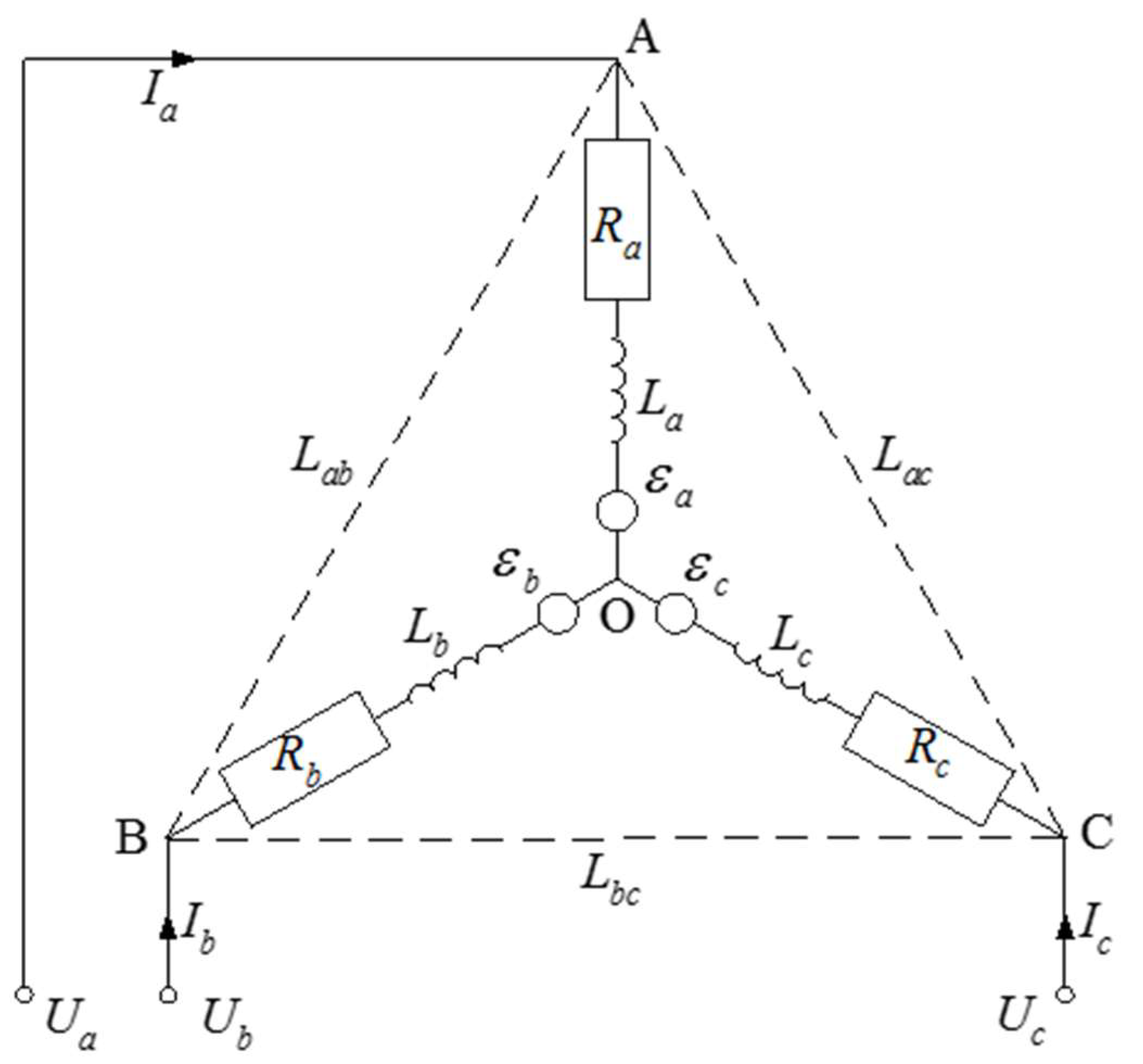
Since the design of the PMSM motor is very similar to the BLDC motor, whose modelling and simulation we have previously addressed [5], the modeling of the PMSM motor is based on that earlier model. Figure 5 shows a model of a PMSM motor with a star-coupled stator.
Based on the model, the following equations can be written:
U a = R a · I a + L a · d I a d t + L a b · d I b d t + L a c · d I c d t + ε a
U b = R b · I b + L b a · d I a d t + L b · d I b d t + L b c · d I c d t + ε b
U c = R c · I c + L c a · d I a d t + L c b · d I b d t + L c · d I c d t + ε c
where, U a , U b and U c are the electric potential of points A, B and C. The R a , R b , R c , L a , L b and L c are the electrical resistances and self-inductances of each winding, L a b , L a c , L b a , L b c , L c a and L c b are mutual inductances between the pairs of windings, ε a , ε b és ε c are the back electromotive forces (Counter or Back EMF) generated by the permanent magnet rotor in the stator windings.
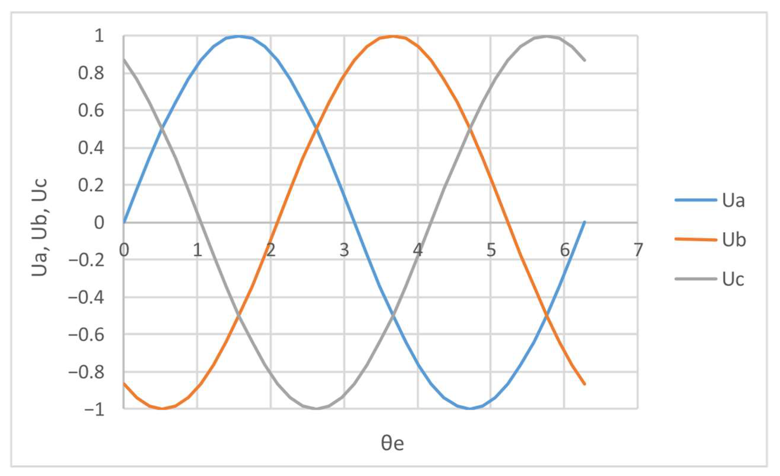
For one pair of poles and a peak voltage of 2 [V], the voltages applied by the motor control electronics to each winding can be given as a function of the electrical angle ( θ e ):
U a = U 0 · sin ( θ e )
U b = U 0 · sin θ e 2 π 3
U c = U 0 · sin θ e 4 π 3
The electric angle ( θ e ) can be calculated from the angular position of the rotor ( θ r ) using the following equation:
θ e = p 2 · θ r
where p 2 is the number of pairs of poles of permanent magnets in the rotor. The Figure 6 shows the U a , U b and U c voltages as a function of electrical angle for a peak voltage is 2 [V] and the pair of poles is p 2 = 1 .
The control electronics, including the electronically controlled commutation system, are not described here. The windings are identical in all respects, and a magnetically linear approximation is used in the modelling, i.e., the inductances are constant:
R = R a R b R c
L = L a L b L c
M = L a b L b a L a c L c a L b c L c b
where R and L are the electrical resistances and self-inductances of each winding and M is the mutual inductance between pairs of windings.
In conclusion:
U a = R a · I a + L · d I a d t + M · d I b d t + M · d I c d t + ε a
U b = R b · I b + M · d I a d t + L · d I b d t + M · d I c d t + ε b
U c = R c · I c + M · d I a d t + M · d I b d t + L · d I c d t + ε c
Applying Kirchhoff’s nodal law at the star point O (Figure 5) yields the following:
I a + I b + I c = 0 d I a d t + d I b d t + d I c d t = 0
Therefore:
d I b d t + d I c d t = d I a d t
d I a d t + d I c d t = d I b d t
d I a d t + d I b d t = d I c d t
By using this:
U a = R · I a + ( L M ) · d I a d t + ε a
U b = R · I b + ( L M ) · d I b d t + ε b
U c = R · I c + ( L M ) · d I c d t + ε c
The back electromotive forces can be calculated as follows:
ε a = d Ψ a d t d Ψ a d θ r · d θ r d t d Ψ a d θ r · ω r k B · F ( s i n ( θ e ) ) · ω r
ε b = d Ψ b d t d Ψ b d θ r · d θ r d t d Ψ b d θ r · ω r k B · F s i n θ e 2 π 3 · ω r
ε c = d Ψ c d t d Ψ c d θ r · d θ r d t d Ψ c d θ r · ω r k B · F s i n θ e 4 π 3 · ω r
In the above equations ω r is the angular speed of the rotor, and d Ψ a d θ r is the derivative of the magnetic flux of the winding with angle θ r , which traditionally given by k B · F ( s i n ( θ e ) ) , where k B is the Back EMF constant and the function F s i n ( θ e ) is interpreted by for a pair of poles:
F a = F s i n ( θ e )
F b = F s i n θ e 2 π 3
F c = F s i n θ e 4 π 3
It should be noted here that the theoretically assumed sinusoidal shape of the Back EMF may deviate from the sinusoidal shape in practice due to the effect of permanent magnets. Thus, for a more accurate simulation, it is worth experimentally determining the Back EMF (see Section 3.4.1) and using the measured values in the simulation (e.g., in the form of a “look-up table”).
Equation of motion for the motor rotor:
i M i = M m o t o r M r e s M l o a d J r · Ɛ r
where M m o t o r is the electromagnetic torque of the motor, M r e s is the friction (resistance) torque, M l o a d is the load on the motor, J r is the moment of inertia of the rotor, and Ɛ r is the acceleration of the rotor.
The electromagnetic torque can be calculated here using the following equation:
M m o t o r = P ω r ε a · I a + ε b · I b + ε c · I c ω r k B · ω r · F s i n ( θ e ) · I a + F s i n θ e 2 π 3 · I b + F s i n θ e 4 π 3 · I c ω r k B · F s i n ( θ e ) · I a + F s i n θ e 2 π 3 · I b + F s i n θ e 4 π 3 · I c
where P is the power of the motor.

3.2. Simulation of the Permanent Magnet Synchronous Motor (PMSM)

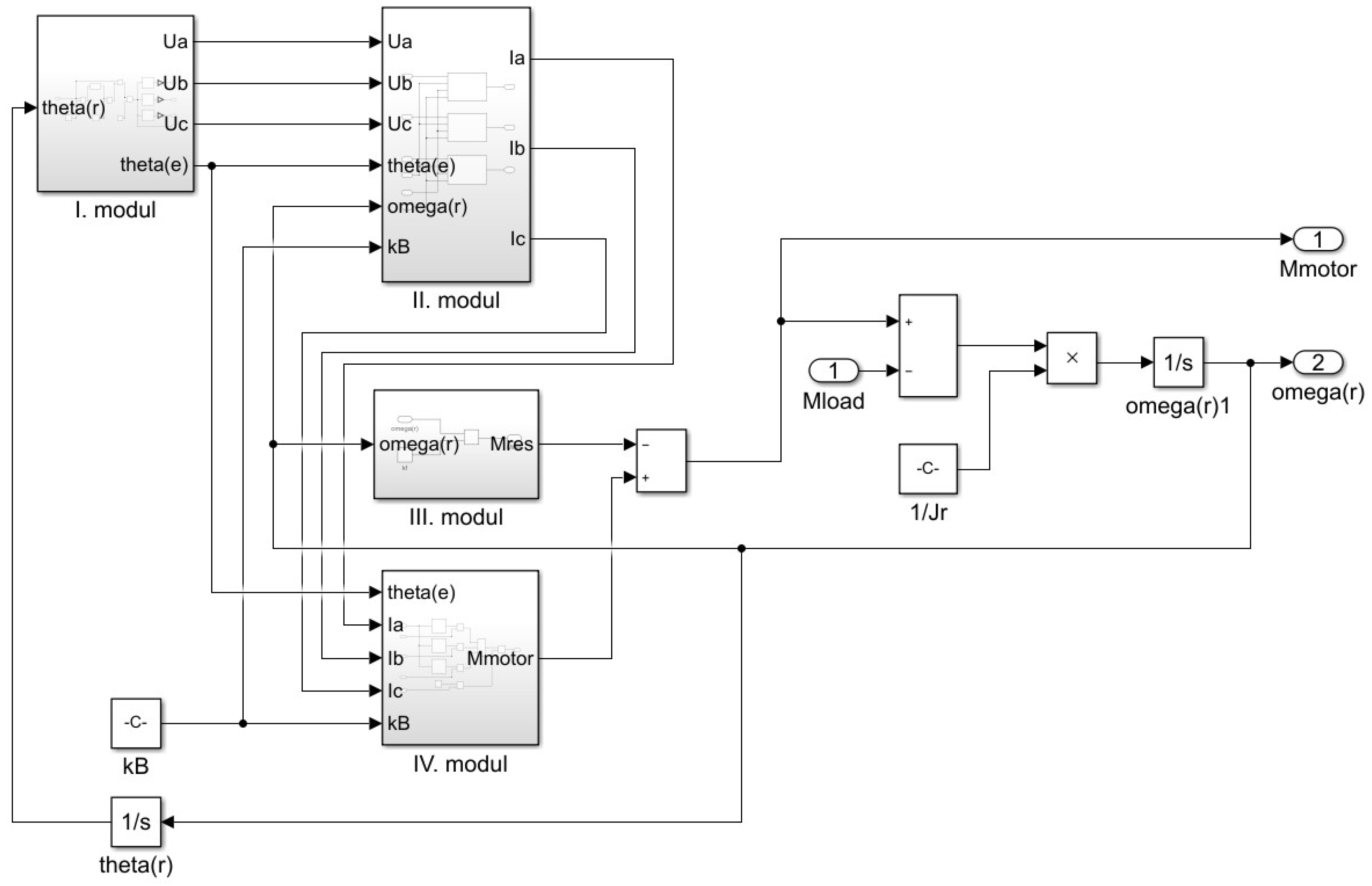
Based on the model described in Section 3.1, a simulation module for the PMSM motor was created using MATLAB Simulink software (R2022b), which is illustrated in Figure 7.
The internal structure and operation of each module is described in detail below.
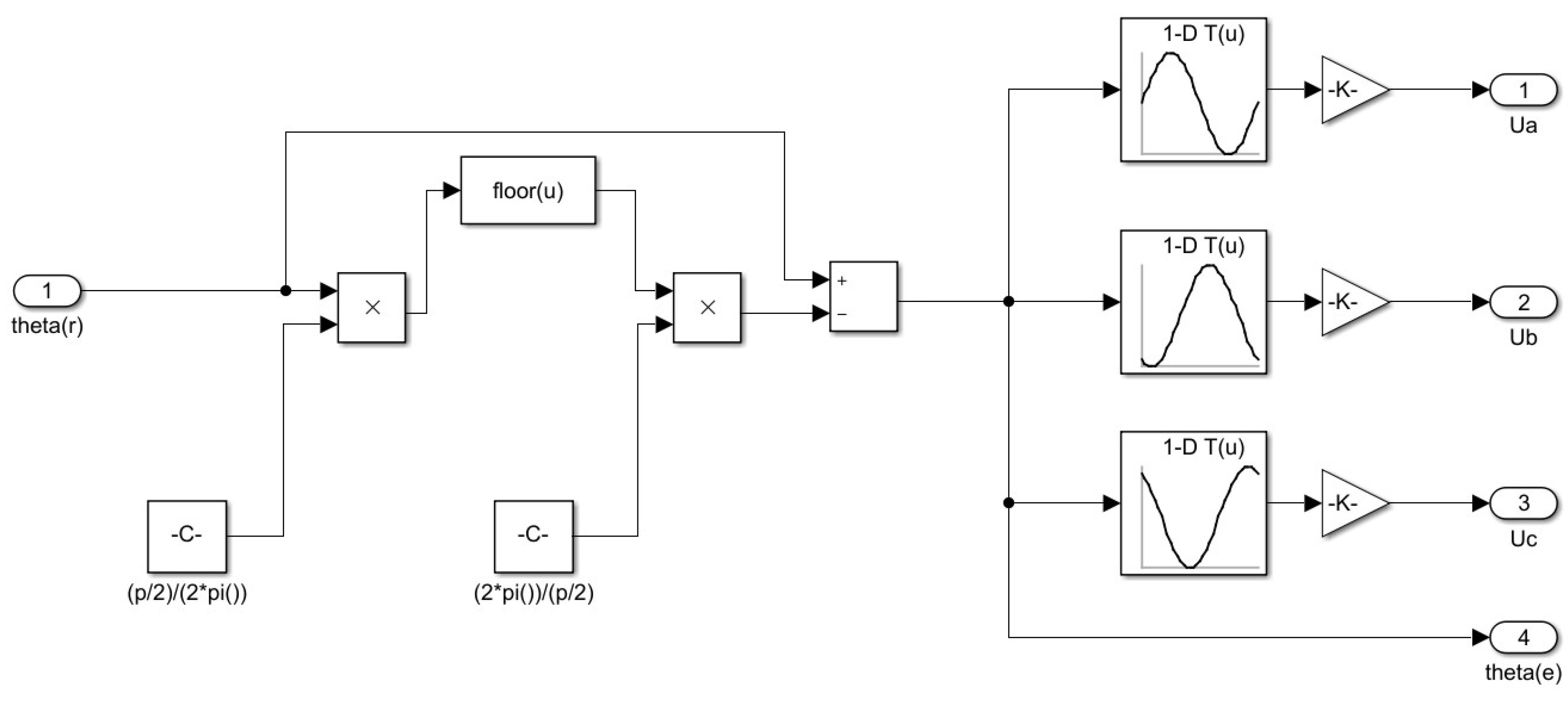
The Module I in Figure 8 is calculated the U a , U b and U c voltages and the electrical angle ( θ e ) from the angular position of the rotor θ r and the number of pole pairs p 2 based on Equations (4)–(7) in Section 3.1. The U a , U b and U c voltage waveforms shown in Figure 6, were fitted as a “look-up table” as a function of electrical angle, and then multiplied by the nominal voltage.
Description of Module II:
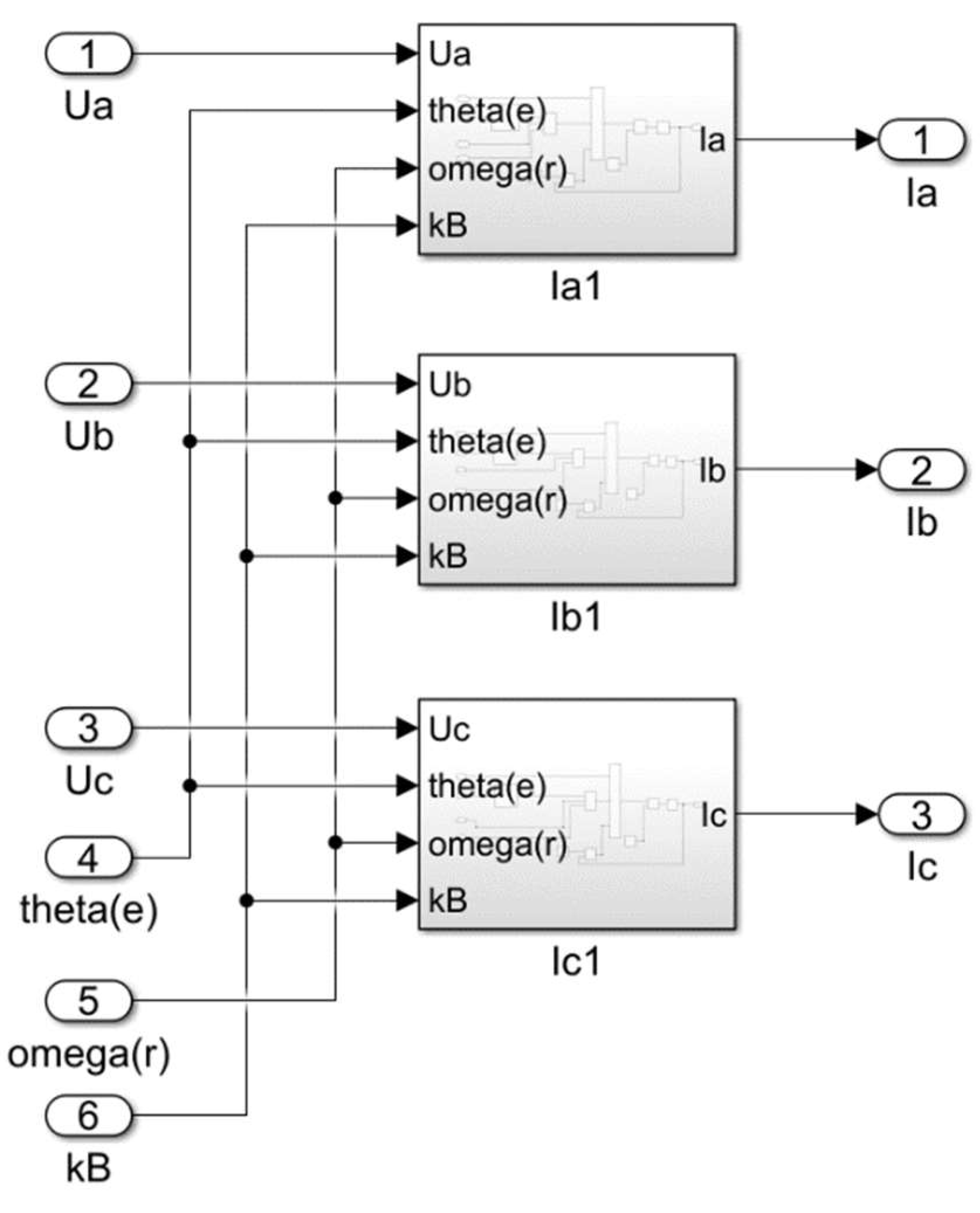
The Module II in Figure 9 is calculate the currents I a , I b and I c from the U a , U b and U c voltages and the electrical angle θ e , as well as the angular velocity of the rotor ( ω r ) and the Back EMF constant ( k B ).
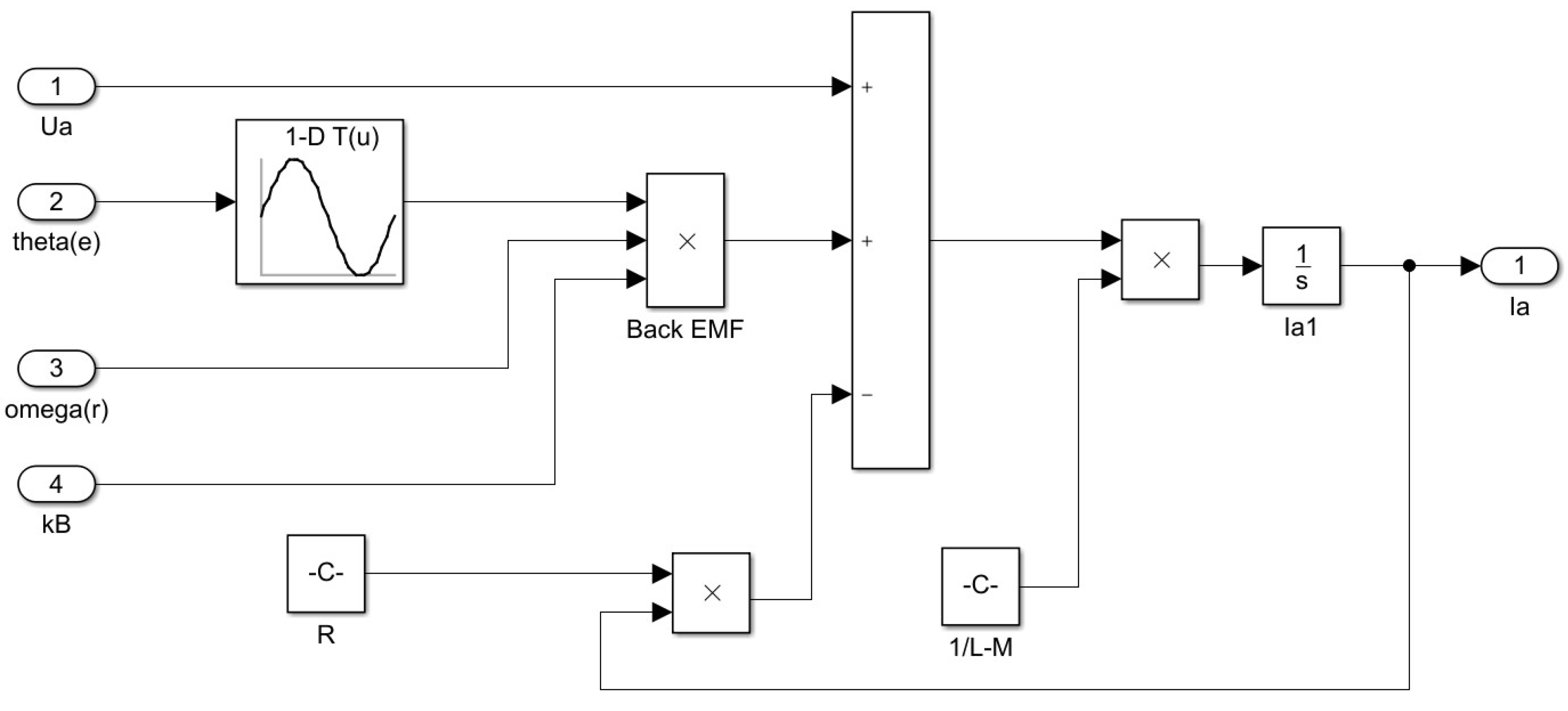
The currents are calculated in separate internal modules based on Equations (18)–(26) in Section 3.1. Figure 10 shows the structure of the internal module that calculates the current I a . (For currents I b and I c , the modules are similar.)
In the internal module that calculates the I a current, the sinusoidal function in Equation (24) is incorporated in the form of a “look-up table”, while the other motor characteristics ( R ,   L ,   M ) are in the form of constants.
Description of Module III:
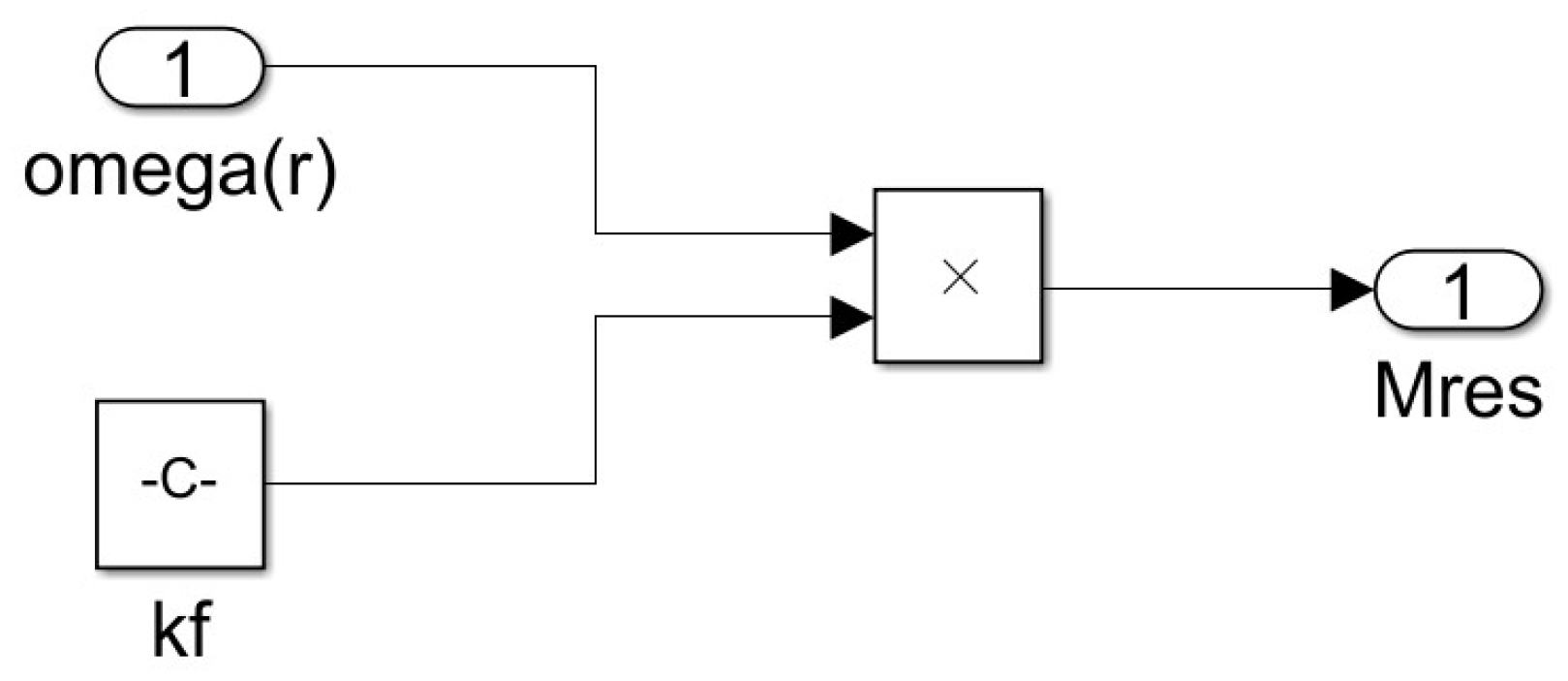
The Module III in Figure 11 calculates the bearing resistance (friction) torque ( M r e s ) of the motor from the angular velocity of the rotor ( ω r ) and the bearing friction factor ( k f ).
Description of Module IV:
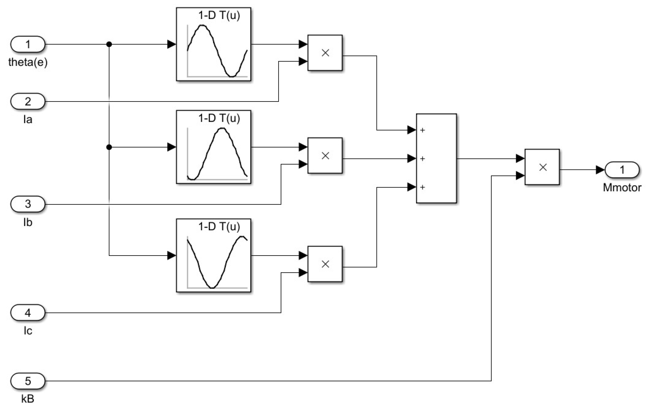
The Module IV in Figure 12 reads in the current intensity I a , I b and I c , the electrical angle ( θ e ) and the Back EMF constant ( k B ) , and calculate the electromagnetic torque ( M m o t o r ) of the motor based on Equation (28) in Section 3.1.
The sinusoidal functions in the equation, which give the shape of the Back EMF for each winding, are incorporated in the form of a “look-up table”.

3.3. The Functions Obtained by Simulation

Since the BLDC and PMSM motors are similar in design, and thus the modelling and simulation are similar, simulations were performed with both motors and compared the resulting functions. The input data of the motors were the same in both cases, namely: rated power: 1.4 [kW]; rated DC voltage: 100 [V], phase resistance: 0.28 [Ω], phase inductance: 0.24 [mH], bearing friction factor ( k f ): 0.001 [Nms], moment of inertia of the rotor: 0.002139 [kgm2], Back EMF konstans ( k B ): 0.0033 [V/(r/min)] [31].
In addition, for both motors the load torque is set to M l o a d = 10   [ N m ] . A detailed description of the BLDC motor simulation program can be found in [5]. To run the simulation, we used the default settings of Simulink (solver: ode45, with variable step size, automatic minimum, maximum and initial step size, and automatic tolerance). In the case of the “look-up tables”, we used the “Linear point-slope” interpolation method.
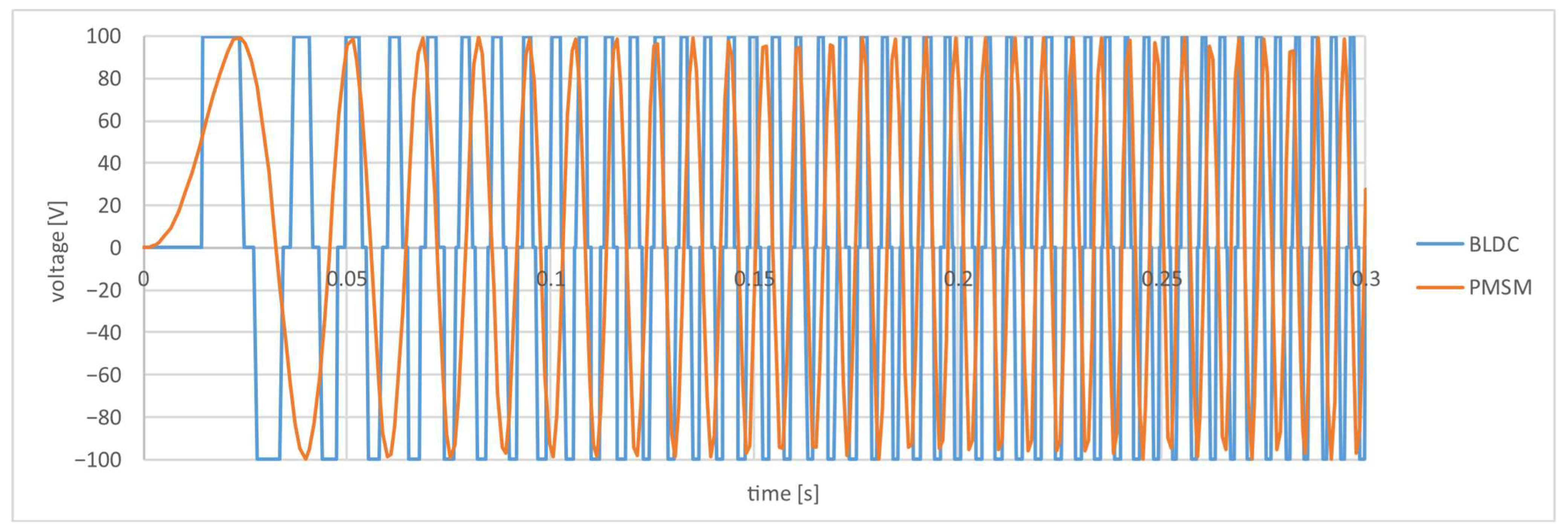
Figure 13 shows the simulated voltage-time functions of the motors for one phase in the time interval 0–0.3 s.
The Figure 13 shows the voltage waveforms on one phase and shows that the BLDC motor spins up faster at the same load and peak voltage. Figure 14 shows the current intensity versus time function through the motors in one phase.
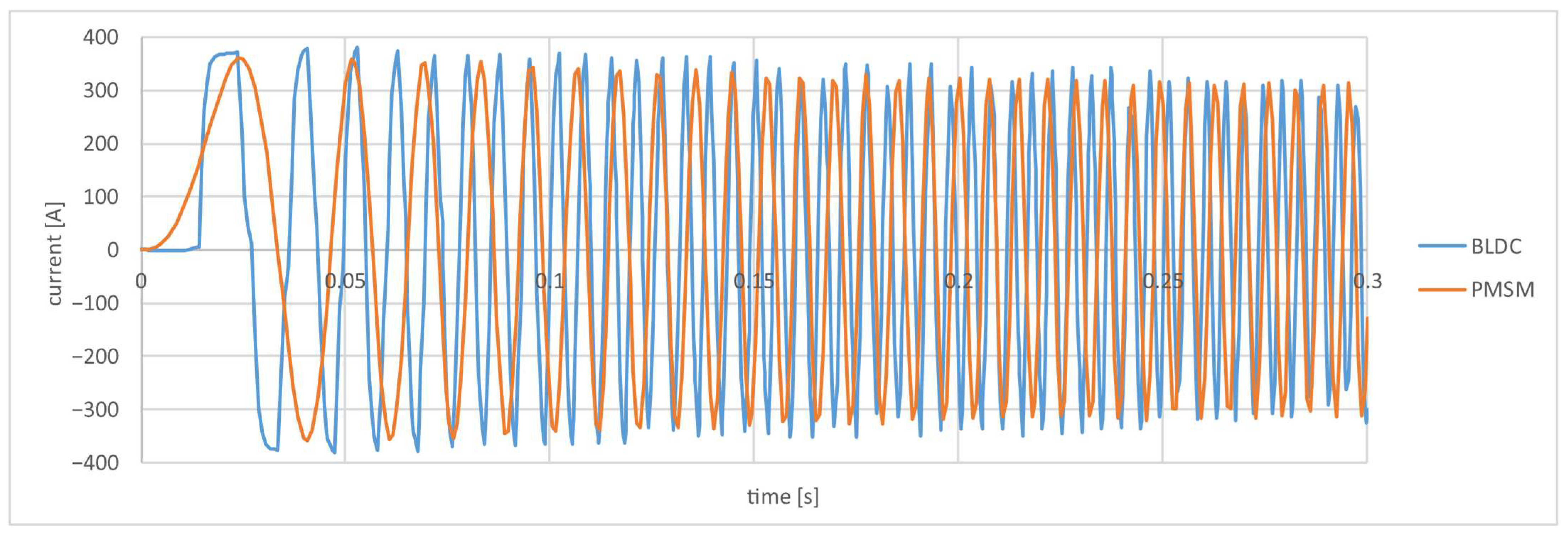
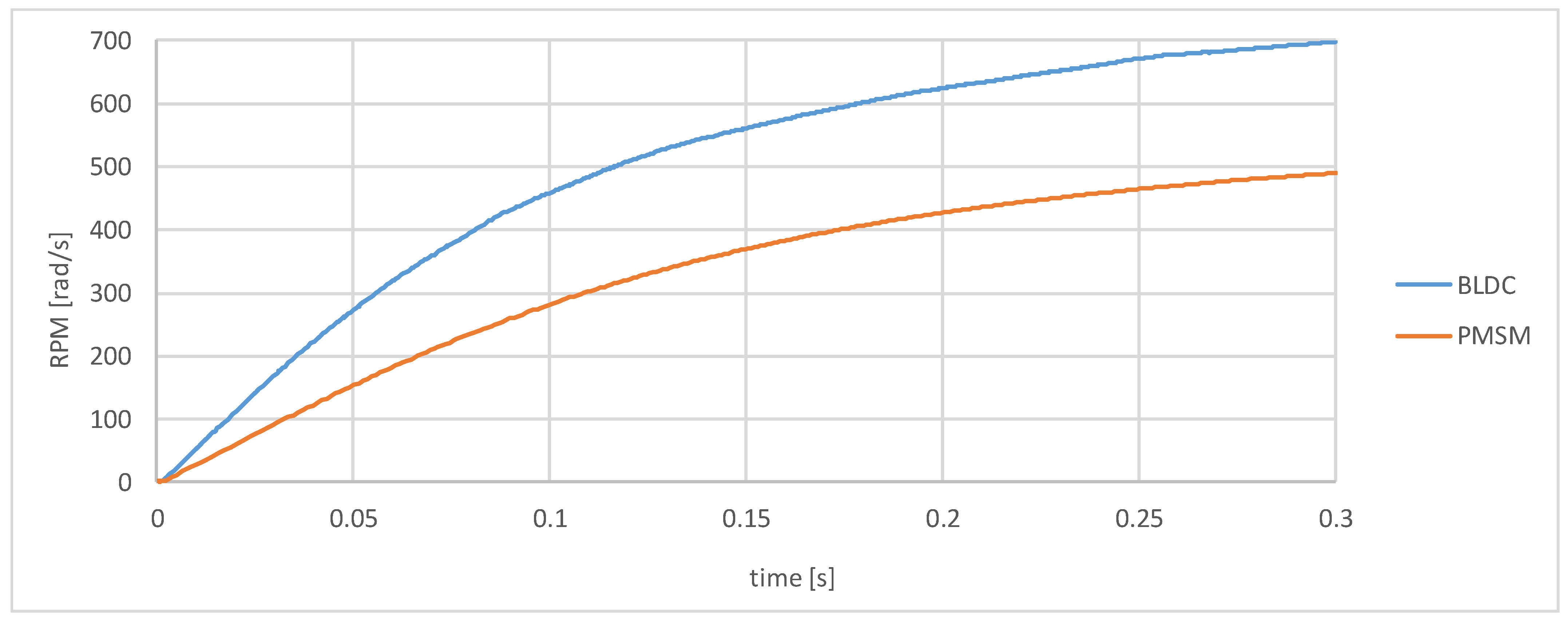
The current intensity-time function behaves similarly to the voltage during the simulation. Figure 15 shows the angular speed-time functions of the motors.
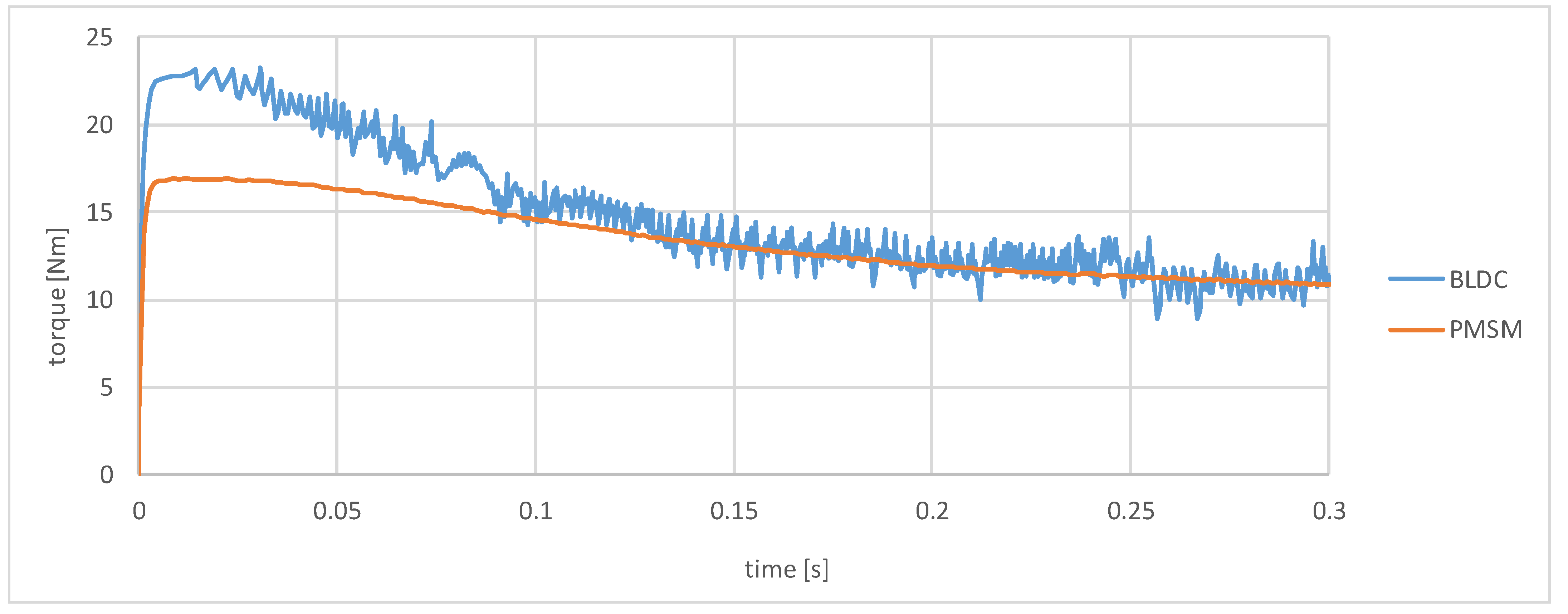
The Figure 15 shows that the BLDC motor spins up to a significantly higher speed in 0.3 s than the PMSM motor. Figure 16 shows the torque-time dependence of the motors.
The maximum torque of the BLDC motor is substantially higher, after this first section, the torque of both motors approaches the 10 Nm value set for the load. It can also be seen that the function obtained with the PMSM motor is much smoother.
The differences between the simulated functions above are presumably caused by differences in the supply voltage and the Back EMF signal waveforms. Thus, based on the above, it can be said that for BLDC and PMSM motors of the same power, this power can be achieved with different motor characteristic parameters.
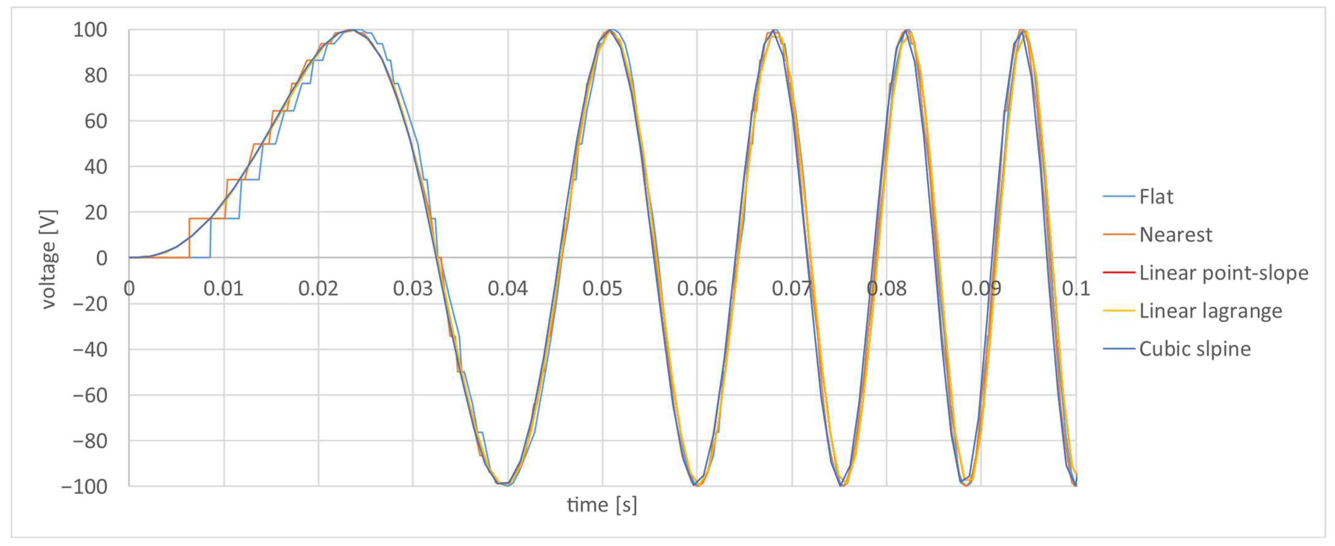
In Figure 17, in case of the voltage-time function of the PMSM motor, we compared the interpolation methods that can be set in the “look-up tables”. These interpolation methods are: Flat, Nearest, Linear point-slope, Linear lagrange, Cubic spline.
The figure shows that the Flat and Nearest methods are less accurate, while the Linear point-slope, Linear lagrange, and Cubic spline methods give very similar results.

3.4. Determination of Motor Characteristics for Permanent Magnet Synchronous Motor (PMSM) Simulation

To run the simulation program, required the motor characteristics described in the previous sections. These, or part of them, are provided by the manufacturer in some cases, but the unknown data must be determined experimentally with the highest possible accuracy to ensure the most accurate simulation. In our previous research, we have dealt with the experimental investigation of different types of electric motors [15,16,17,18], so we use the experience gained from that research to describe the experiments designed to determine the different characteristics of the PMSM motor and the corresponding measurement setups.
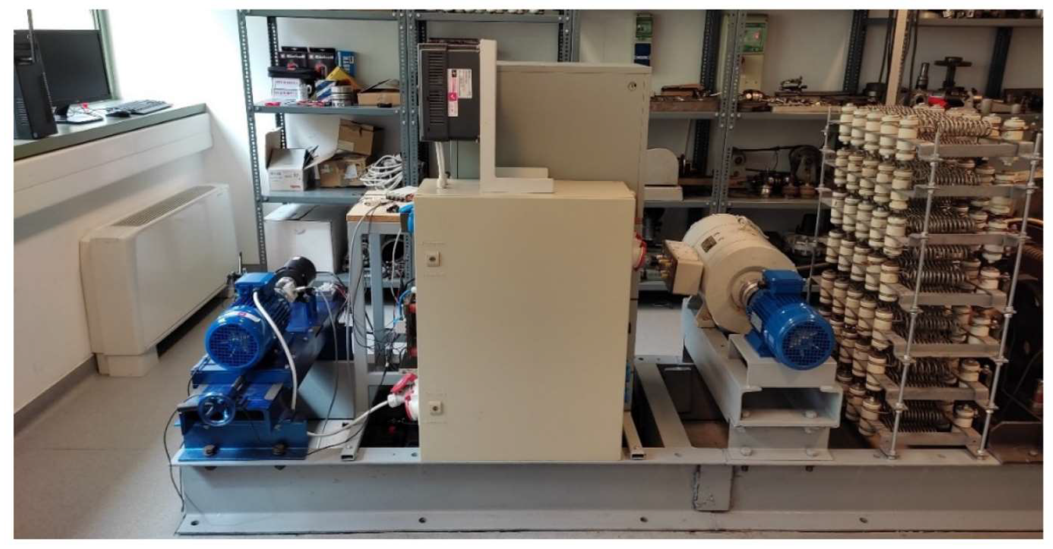
To test electric motors, we have developed a complex measurement system (Figure 18) that is flexible enough to be used for different types of motors and experiments. A detailed description of the measurement system can be found in [22].
For the PMSM motor, the following characteristics are planned to be experimentally determined: Back EMF, electric resistance, self- and mutual inductance of the windings, and moment of inertia and friction torque of the rotor.

3.4.1. Experimental Determination of Back Electromotive Force (Back EMF)

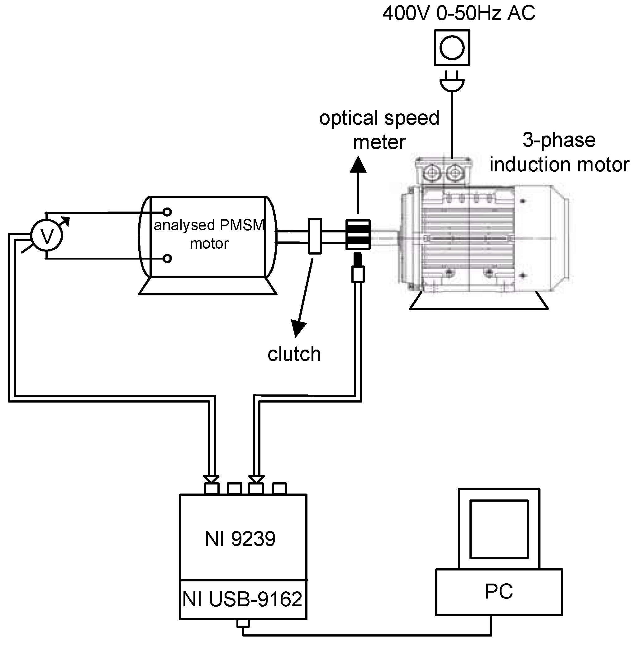
We plan to experimentally determine the Back EMF in one phase using the measurement setup shown in Figure 19. In the experiment, the analyzed PMSM motor is connected via a clutch to a 3-phase asynchronous motor that drives the analyzed PMSM motor. The experiment can then be performed at different speeds, while measuring the speed and the voltage induced on a phase of the analyzed PMSM motor. The measured characteristics would then be given into the simulation program as a “look-up-table”. A detailed description of the sensors used for the measurement and the data acquisition system can be found in [22].

3.4.2. Experimental Determination of Electric Resistance of Windings

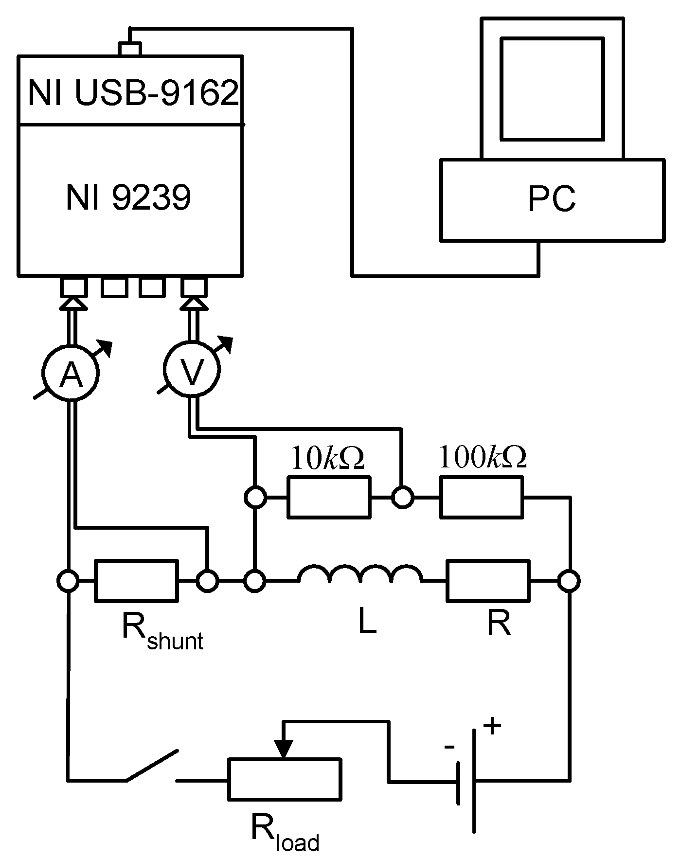
During the measurements, the motor rotor is fixed by a disc brake, thus eliminating the voltage induced by one winding in the other. The measurements require a strictly constant DC current, which can be provided by a car battery with a nominal voltage of 12 [V], for example. By varying the value of the load resistance ( R l o a d ), we can control the current flowing through the winding, so that measurements can be made at different current levels. The measurement of the current intensity is reduced to the measurement of the voltage across a shunt resistor. Thus, from the resulting current and voltage measured on a voltage divider, the electric resistance of the winding can be determined. The measuring arrangement is shown in Figure 20.

3.4.3. Experimental Determination of Self- and Mutual Inductance of Windings

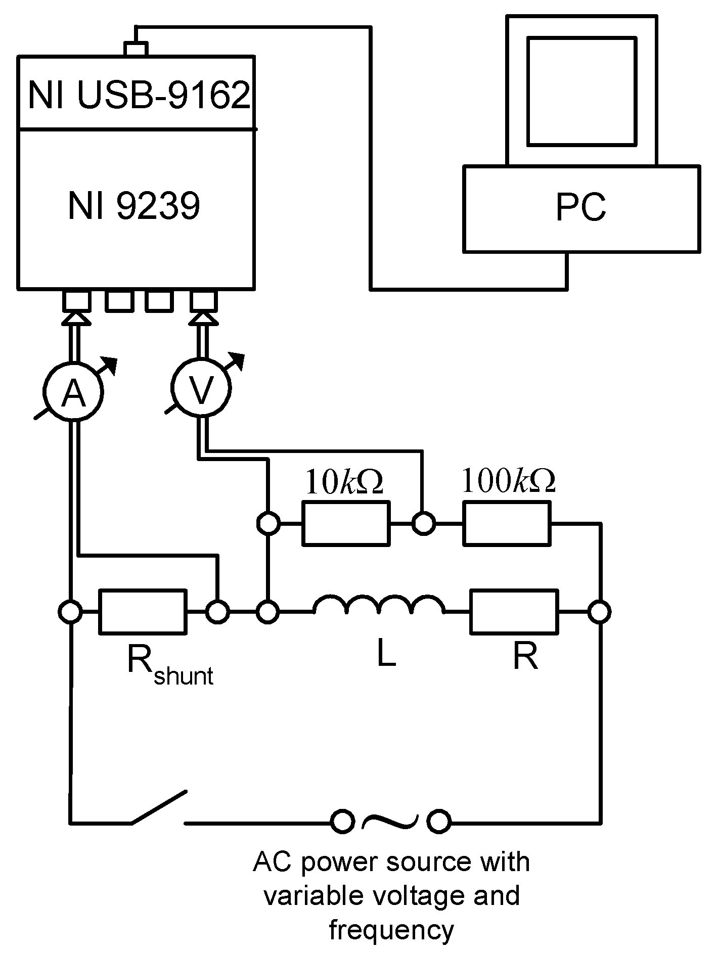
To determine the self- and mutual inductance of the windings, the measuring arrangement shown in Figure 21 can be used.
To measure the self-inductance of the winding, the winding is excited with an AC voltage. The excitation can be performed at different frequencies (5, 10, 50 [Hz]) with a number of different peak AC voltages at each frequency. The intensity of the current flowing through the winding ( I ( t ) ) is measured as a function of time using a shunt resistor. The voltage across the windings is measured using a voltage divider.
From the voltage across the winding ( U ( t ) ) and the intensity of the current flowing through it ( I ( t ) ), the magnetic flux of the winding as a function of time can be calculated using the following equation:
Ψ t = 0 t U τ I τ · R d τ + Ψ 0
In the above equation,   U τ I τ · R is the self-induced voltage in the winding. Knowing the functions t and I t , the magnetic flux can be given as a function of the current ( I ). Then, by deriving this from the variable I, the dynamic self-inductance L I is obtained as a function of the current.
To determine the mutual inductances, the above measurement setup and method can be used, with the difference that in this case one winding is excited while the current is measured in another winding.

3.4.4. Experimental Determination of the Moment of Inertia and the Resistance Torque of the Rotor

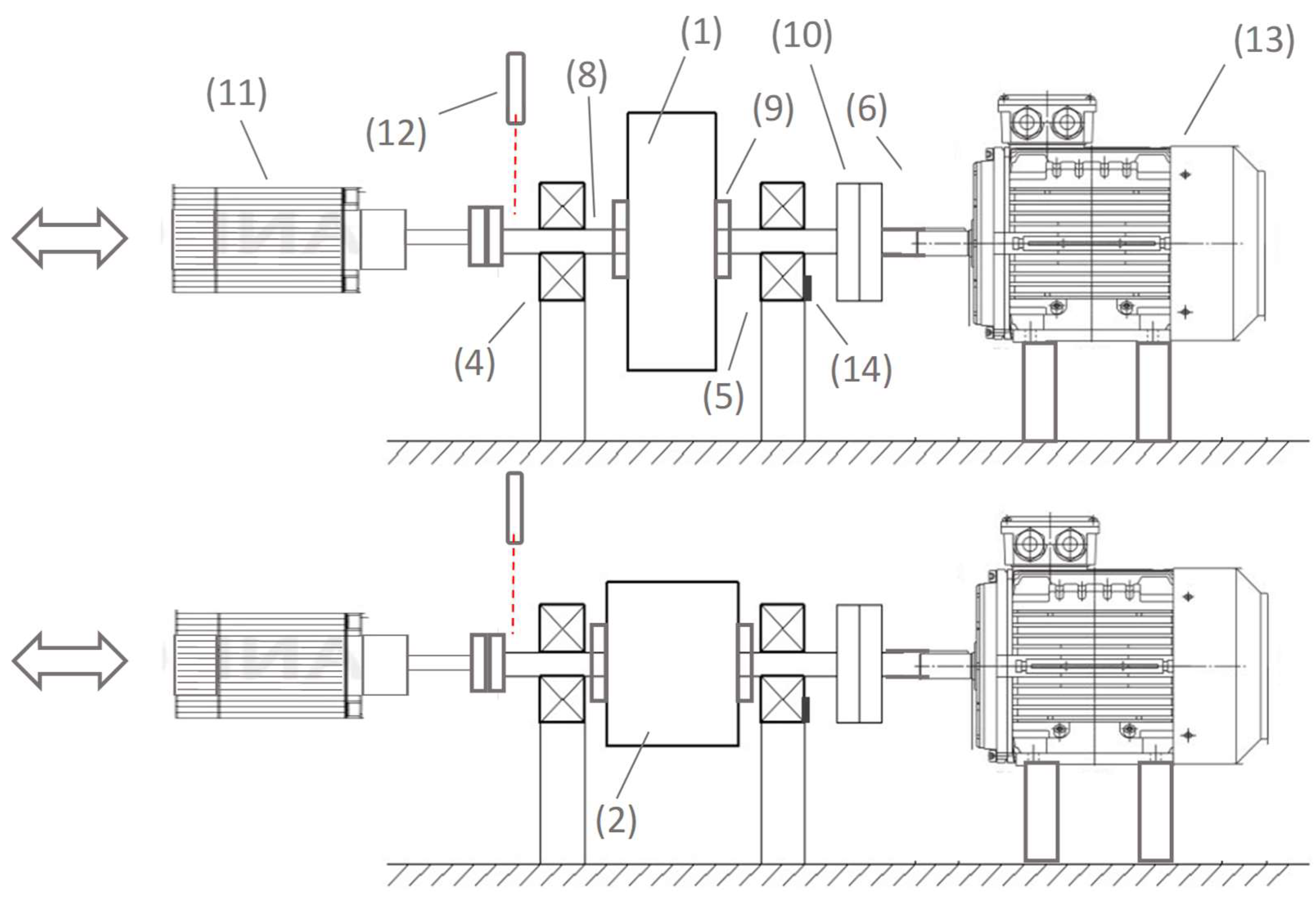
There are several methods for the experimental determination of rotor moments of inertia and its resistance torque, which are summarized in [17]. Among the methods presented, the most suitable is the method described in detail in [18], where the two quantities are determined simultaneously without disassembling the motor. The corresponding measurement setup is shown in Figure 22.
The procedure is based on four independent measurements. For each of the four measurements, an external motor (11) is used to accelerate (spin up) the system from a stationary position, and then the acceleration motor is disengaged from the system after the maximum speed is reached.
For the first two measurements, the system is allowed to decelerate by removing the clutch (10) between the motor under test (13) and the load cylinders (1, 2), while for the other two measurements the clutch is maintained throughout, thus slowing down the motor under test and the load cylinders together until a standstill is reached.
For these two measurements, the moments of inertia of the load cylinders (1) and (2) are different, but their masses are the same. The identical masses ensure the same radial loading of the bearings (4, 5), and thus the same friction torques in the bearings for a given speed and temperature. In the experiments, the speed of the system is measured (12) as a function of time.
Four independent dynamic equations can be written for the run-out phase of the four independent experiments, and the resulting system of equations can be used to calculate the inertia and the friction torque of the rotor. It is important to note that the method can only achieve sufficient accuracy if the moments of inertia of the load cylinders are chosen appropriately for the motor under test. This is described in detail in [18].

4. Comparison of PMSM and BLDC Motor Simulation in a Prototype Race Car

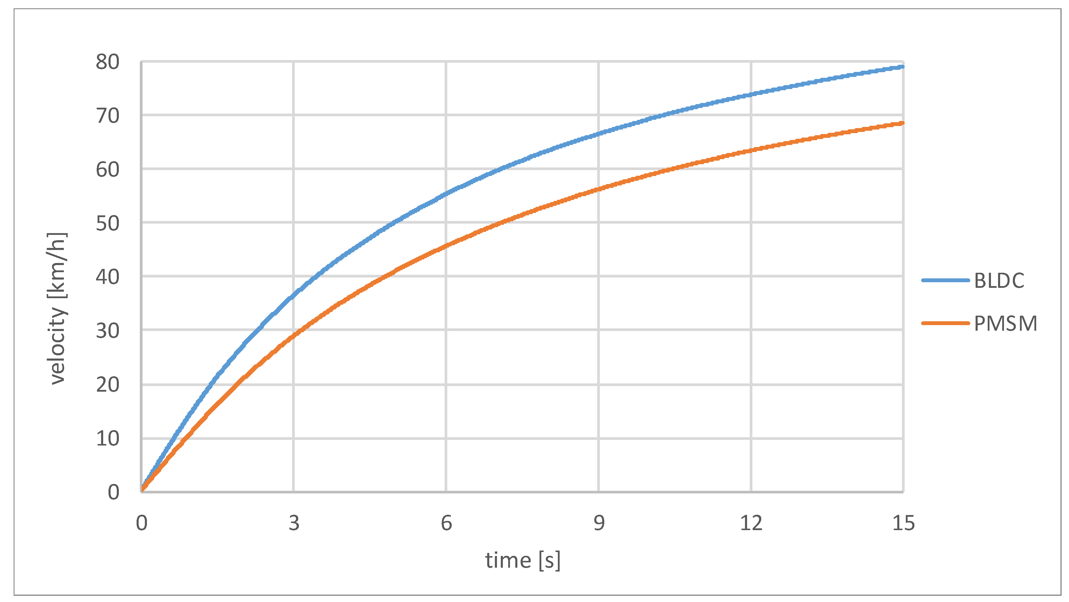
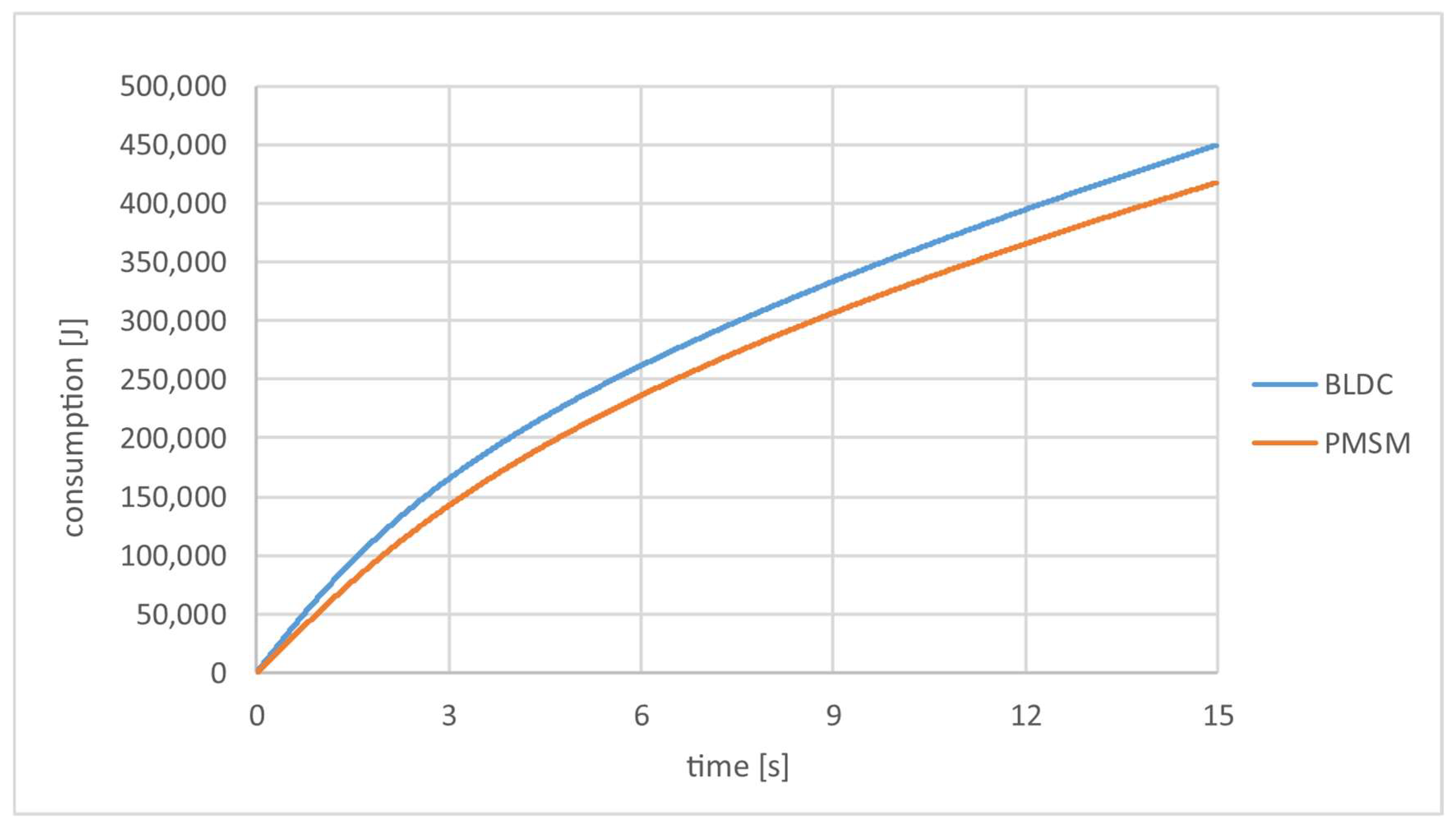
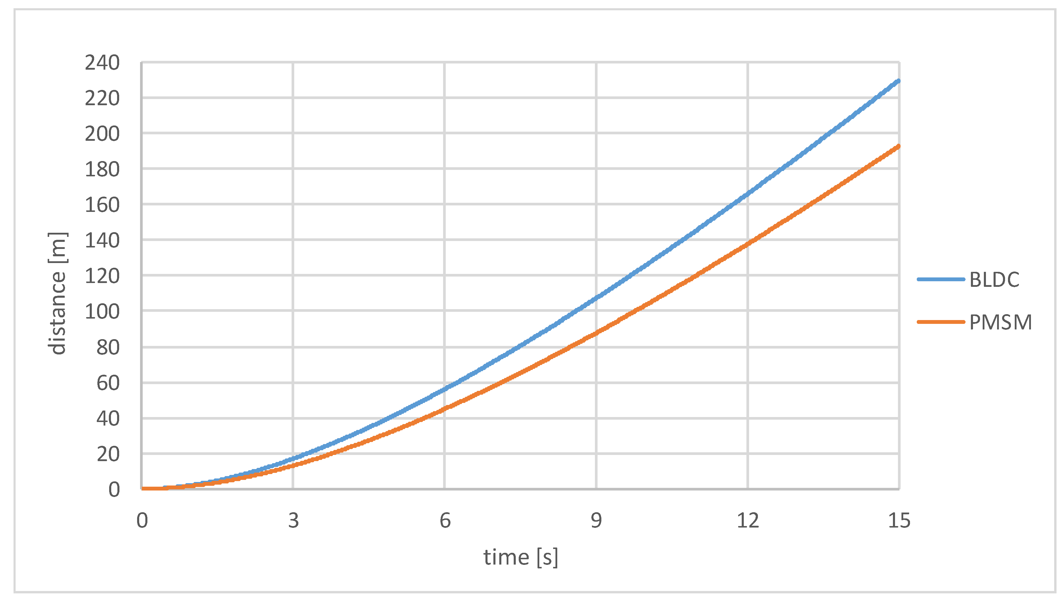
The PMSM motor simulation module presented in Section 3 was integrated into the previous vehicle dynamics simulation program [4]. The simulation program was then run using the same vehicle and motor parameters (see Section 3) for both PMSM and BLDC motors. During the simulation, the vehicle accelerated for 15 s from a stationary start. The speed-time, energy consumption-time and travelled distance-time functions obtained with the two motors are shown in Figure 23, Figure 24 and Figure 25.
The Figure 23 and Figure 25 shows that between PMSM and BLDC motors simulated with the same motor parameters and peak voltage, the car with the BLDC motor accelerates faster in 15 s. In 15 s, the vehicle powered by a PMSM motor accelerates to 68.5 km/h while traveling 192.78 m. A vehicle powered by a BLDC motor accelerates to 79 km/h in the same time, while traveling 229.7 m. The BLDC motor is the better choice in terms of performance, especially for competitive tasks that require higher power, such as a drag race. For example, if we look at a 150-m drag race, the PMSM motor-powered vehicle completes the distance in 12.69 s (at a speed of 64.74 km/h), while the BLDC motor-powered vehicle completes it in only 11.22 s (at a speed of 72.17 km/h), which is a significant time difference in a drag race.
However, Figure 24 also shows that the PMSM motor consumes less energy during the given time, making it the better choice for an energy consumption race (e.g., Shell ECO-Marathon race). However, if we consider the energy consumption over a given distance (e.g., 150 m), there is no big difference between the two motors (PMSM: 378,211.8 J, BLDC: 379,534.9 J).
It is important to note, however, that when designing a car for a specific competition task, it is advisable to simulate the specific motor (which may require experimental determination of various motor parameters) and then optimize the vehicle and motor specifications for the specific competition purpose. This type of optimization can be found in [31].

5. Conclusions

This paper addresses the modeling and simulation of a PMSM motor. Taking into account the modelling procedures mentioned in the literature, a novel custom model was developed and, based on it, a simulation module for the motor was created using MATLAB Simulink software to align with an existing vehicle dynamics simulation program. The above module is a universal simulation module for PMSM motors, which is also suitable for motor simulation on its own, and thus provides the opportunity to optimize various motor data. It can also be integrated into a vehicle dynamics simulation program, which can be used to perform driving dynamics analysis of electric prototype race cars, for example. Then, for the same motor parameters, the results obtained for the PMSM motor were compared with those from a previously prepared BLDC motor simulation.
Furthermore, the PMSM motor simulation module was integrated into the vehicle dynamics simulation program and compared the simulation results for the same model parameters. Thus, the developed motor simulation module and the results obtained with it provide help in selecting the appropriate motor types when designing new electric vehicles for a specific task.
Since simulating a specific motor requires detailed motor specifications, which are sometimes not provided by the manufacturer, unique measurement procedures for experimentally determining these specifications have also been described. The outcomes build upon prior experience in this field.
Thus, in this publication, a comprehensive overview of the modelling and simulation of the PMSM motor and the experimental determination of the technical input data required for the simulation is presented.
Our future plans include experimentally determining motor characteristics and conducting test measurements. This way, we can determine the accuracy of our model, and we plan to examine how the neglect of various effects used in the model (magnetic saturation, magnetic flux nonlinearity, cogging torque, reluctance torque, and iron losses occur) affects the accuracy under both static and dynamic conditions.

Author Contributions

Conceptualization, A.S.; methodology, A.S. and M.A.; software, T.P.K. and S.S.D.; validation, M.A.; formal analysis, T.P.K. and M.A.; investigation, A.S.; writing—original draft preparation, A.S. and M.A.; writing—review and editing, T.P.K. and S.S.D.; visualization, A.S. and M.A.; project administration, A.S.; All authors have read and agreed to the published version of the manuscript.

Funding

This research was funded by University of Debrecen.

Data Availability Statement

The original contributions presented in the study are included in the article, further inquiries can be directed to the corresponding author.

Acknowledgments

This research was supported by the “University of Debrecen Program for Scientific Publication”. “Supported by the EKÖP-24-4 University Research Scholarship Program of the Ministry for Culture and Innovation from the source of the National Research, Development and Innovation Fund.”

Conflicts of Interest

The authors declare no conflicts of interest.

References

  1. Cao, W.; Bukhari, A.A.S.; Aarniovuori, L. Review of electrical motor drives for electric vehicle applications. Mehran Univ. Res. J. Eng. Technol. 2019, 38, 525–540. [Google Scholar] [CrossRef]
  2. Cai, W.; Wu, X.; Zhou, M.; Liang, Y.; Wang, Y. Review and development of electric motor systems and electric powertrains for new energy vehicles. Automot. Innov. 2021, 4, 3–22. [Google Scholar] [CrossRef]
  3. Bhatt, P.; Mehar, H.; Sahajwani, M. Electrical motors for electric vehicle–a comparative study. In Proceedings of the Recent Advances in Interdisciplinary Trends in Engineering & Applications (RAITEA), Indore, India, 3 April 2019. [Google Scholar]
  4. Szántó, A.; Hajdu, S.; Sziki, G.Á. Dynamic simulation of a prototype race car driven by series wound DC motor in Matlab-Simulink. Acta Polytech. Hung. 2020, 17, 103–122. [Google Scholar] [CrossRef]
  5. Szíki, G.Á.; Szántó, A.; Mankovits, T. Dynamic modelling and simulation of a prototype race car in MATLAB/Simulink applying different types of electric motors. Int. Rev. Appl. Sci. Eng. 2021, 12, 57–63. [Google Scholar] [CrossRef]
  6. Haigang, Z.; Weiguo, Q.; Yanxiang, W.; Shihong, G.; Yuan, Y. Modeling and simulation of the permanent-magnet synchronous motor drive. In Proceedings of the 2011 International Conference on Uncertainty Reasoning and Knowledge Engineering, Bali, Indonesia, 4–7 August 2011; IEEE: Piscataway, NJ, USA, 2011; Volume 2, pp. 256–260. [Google Scholar]
  7. MAGNET, S.O.P. Mathematical modeling and simulation of permanent magnet synchronous motor. Int. J. Adv. Res. Electr. Electron. Instrum. Eng. 2013, 3720–3726. [Google Scholar]
  8. Luo, G.; Zhang, R.; Chen, Z.; Tu, W.; Zhang, S.; Kennel, R. A novel nonlinear modeling method for permanent-magnet synchronous motors. IEEE Trans. Ind. Electron. 2016, 63, 6490–6498. [Google Scholar] [CrossRef]
  9. Pillay, P.; Krishnan, R. Modeling, simulation, and analysis of permanent-magnet motor drives. I. The permanent-magnet synchronous motor drive. IEEE Trans. Ind. Appl. 1989, 25, 265–273. [Google Scholar] [CrossRef]
  10. Mersha, T.K.; Du, C. Co-simulation and modeling of PMSM based on ANSYS software and Simulink for EVs. World Electr. Veh. J. 2021, 13, 4. [Google Scholar] [CrossRef]
  11. Mohamed, N.; Aymen, F.; Mouna, B.H.; Lassaad, S. Modeling and simulation of vector control for a Permanent Magnet Synchronous Motor in electric vehicle. In Proceedings of the 2021 4th International Symposium on Advanced Electrical and Communication Technologies (ISAECT), Alkhobar, Saudi Arabia, 6–8 December 2021; IEEE: Piscataway, NJ, USA, 2021; pp. 1–5. [Google Scholar]
  12. Yu, Y.; Huang, X.; Li, Z.; Wu, M.; Shi, T.; Cao, Y.; Yang, G.; Niu, F. Full parameter estimation for permanent magnet synchronous motors. IEEE Trans. Ind. Electron. 2021, 69, 4376–4386. [Google Scholar] [CrossRef]
  13. Wang, Z.; Liu, X.; Wang, W.; Lv, Y.; Yuan, B.; Li, W.; Li, Q.; Wang, S.; Chen, Q.; Zhang, Y. UKF-based parameter estimation and identification for permanent magnet synchronous motor. Front. Energy Res. 2022, 10, 855649. [Google Scholar] [CrossRef]
  14. Ahn, H.; Park, H.; Kim, C.; Lee, H. A review of state-of-the-art techniques for PMSM parameter identification. J. Electr. Eng. Technol. 2020, 15, 1177–1187. [Google Scholar] [CrossRef]
  15. Sziki, G.Á.; Sarvajcz, K.; Kiss, J.; Gál, T.; Szántó, A.; Gábora, A.; Husi, G. Experimental investigation of a series wound dc motor for modeling purpose in electric vehicles and mechatronics systems. Measurement 2017, 109, 111–118. [Google Scholar] [CrossRef]
  16. Szántó, A.; Kiss, J.; Mankovits, T.; Szíki, G.Á. Dynamic Test Measurements and Simulation on a Series Wound DC Motor. Appl. Sci. 2021, 11, 4542. [Google Scholar] [CrossRef]
  17. Sziki, G.A.; Szanto, A.; Adamko, E. Review of methods for determining the moment of inertia and friction torque of electric motors. Acta Polytech. Hung. 2024, 21, 203–218. [Google Scholar] [CrossRef]
  18. Szántó, A.; Ádámkó, É.; Juhász, G.; Sziki, G.Á. Simultaneous measurement of the moment of inertia and braking torque of electric motors applying additional inertia. Measurement 2022, 204, 112135. [Google Scholar] [CrossRef]
  19. Pálinkás, S. Influence of Speed to Rolling Resistance Factor in Case of Autobus. In Vehicle and Automotive Engineering 4: Select Proceedings of the 4th VAE2022, Miskolc, Hungary, Proceedings of the International Conference on Vehicle and Automotive Engineering, Miskolc, Hungary, 8–9 September 2022; Springer International Publishing: Cham, Switzerland, 2022; pp. 157–164. [Google Scholar]
  20. Pálinkás, S.; Tóth, Á. Development of a measurement method to determine rolling resistance. IOP Conf. Ser. Mater. Sci. Eng. 2022, 1237, 012013. [Google Scholar] [CrossRef]
  21. Hadžiselimović, M.; Blaznik, M.; Štumberger, B.; Zagradišnik, I. Magnetically nonlinear dynamic model of a series wound DC motor. Przegląd Elektrotechniczny 2011, 87, 60–64. [Google Scholar]
  22. Sziki, G.Á.; Szántó, A.; Kiss, J.; Juhász, G.; Ádámkó, É. Measurement system for the experimental study and testing of electric motors at the faculty of engineering, University of Debrecen. Appl. Sci. 2022, 12, 10095. [Google Scholar] [CrossRef]
  23. Espanet, C.; Kauffmann, J.M.; Bernard, R. Comparison of two in-wheel permanent magnet motors for military applications. In Proceedings of the 2006 IEEE Vehicle Power and Propulsion Conference, Windsor, UK, 6–8 September 2006; IEEE: Piscataway, NJ, USA, 2006; pp. 1–6. [Google Scholar]
  24. Lidozzi, A.; Solero, L.; Crescimbini, F.; Di Napoli, A. SVM PMSM drive with low resolution Hall-effect sensors. IEEE Trans. Power Electron. 2007, 22, 282–290. [Google Scholar] [CrossRef]
  25. Tang, L.; Su, G.J. High-Performance Control of Two Three Phase Permanent Magnet Synchronous Machines in an Integrated Inverter for Automotive Applications. In Proceedings of the 2007 IEEE Power Electronics Specialists Conference, Orlando, FL, USA, 17–21 June 2007; IEEE: Piscataway, NJ, USA, 2007; pp. 2001–2007. [Google Scholar]
  26. Rahim, N.A.; Hew, W.P.; Mahmoudi, A. Axial-flux permanent-magnet brushless dc traction motor for direct drive of electric vehicle. Int. Rev. Electr. Eng. 2011, 6, 760–769. [Google Scholar]
  27. Dai, P.; Sun, W.; Xu, N.; Lv, Y.; Zhu, X. Research on energy management system of hybrid electric vehicle based on permanent magnet synchronous motor. In Proceedings of the 2016 IEEE 11th Conference on Industrial Electronics and Applications (ICIEA), Hefei, China, 5–7 June 2016; IEEE: Piscataway, NJ, USA, 2016; pp. 2345–2349. [Google Scholar]
  28. Zhu, Z.Q.; Howe, D. Electrical machines and drives for electric, hybrid, and fuel cell vehicles. Proc. IEEE 2007, 95, 746–765. [Google Scholar] [CrossRef]
  29. Usman, A.; Joshi, B.M.; Rajpurohit, B.S. Review of fault modeling methods for permanent magnet synchronous motors and their comparison. In Proceedings of the 2017 IEEE 11th International Symposium on Diagnostics for Electrical Machines, Power Electronics and Drives (SDEMPED), Tinos, Greece, 29 August–1 September 2017; IEEE: Piscataway, NJ, USA, 2017; pp. 141–146. [Google Scholar]
  30. Szántó, A.; Hajdu, S.; Sziki, G.Á. Optimizing parameters for an electrical car employing vehicle dynamics simulation program. Appl. Sci. 2023, 13, 8897. [Google Scholar] [CrossRef]
  31. Liu, G.; Mao, K. A novel power failure compensation control method for active magnetic bearings used in high-speed permanent magnet motor. IEEE Trans. Power Electron. 2015, 31, 4565–4575. [Google Scholar] [CrossRef]
Figure 1. Motor types used in electric vehicles.
Modelling 06 00104 g001
Figure 2. The vehicle dynamics model for the race car together with the forces and torques acting on it [4].
Modelling 06 00104 g002
Figure 3. The simulation program developed in MATLAB Simulink [4].
Modelling 06 00104 g003
Figure 4. Internal structure of a permanent magnet (PM) motor.
Modelling 06 00104 g004
Figure 5. Model of the PMSM motor [5].
Modelling 06 00104 g005
Figure 6. The U a , U b and U c voltages as a function of electrical angle with a peak voltage of 2 [V] and a pair of poles p 2 = 1 .
Modelling 06 00104 g006
Figure 7. The PMSM motor simulation module.
Modelling 06 00104 g007
Figure 8. Module I of the PMSM motor simulation.
Modelling 06 00104 g008
Figure 9. Module II of the PMSM motor simulation.
Modelling 06 00104 g009
Figure 10. Structure of the internal module that calculates the current I a . .
Modelling 06 00104 g010
Figure 11. Module III of the PMSM motor simulation.
Modelling 06 00104 g011
Figure 12. Module IV of the PMSM motor simulation.
Modelling 06 00104 g012
Figure 13. Simulated voltage-time functions of PMSM and BLDC motors.
Modelling 06 00104 g013
Figure 14. Simulated current intensity-time functions of PMSM and BLDC motors.
Modelling 06 00104 g014
Figure 15. Simulated angular speed-time functions of PMSM and BLDC motors.
Modelling 06 00104 g015
Figure 16. Simulated torque-time functions of PMSM and BLDC motors.
Modelling 06 00104 g016
Figure 17. Comparison of interpolation methods.
Modelling 06 00104 g017
Figure 18. The measurement system developed for testing electric motors [22].
Modelling 06 00104 g018
Figure 19. Outline of the measurement setup for the experimental determination of the Back EMF [22].
Modelling 06 00104 g019
Figure 20. Outline of the measurement setup designed for the experimental determination of the electric resistance of windings [22].
Modelling 06 00104 g020
Figure 21. Outline of the measurement setup designed for the experimental determination of the self- and mutual inductance of windings [22].
Modelling 06 00104 g021
Figure 22. Outline of the measurement setup designed for experimental determination of rotor moments of inertia and its resistance torque [18].
Modelling 06 00104 g022
Figure 23. Speed-time function of a prototype race car with PMSM and BLDC motors.
Modelling 06 00104 g023
Figure 24. Energy consumption vs. time of a prototype race car with PMSM and BLDC motors.
Modelling 06 00104 g024
Figure 25. Travelled distance vs. time of a prototype race car with PMSM and BLDC motors.
Modelling 06 00104 g025
Disclaimer/Publisher’s Note: The statements, opinions and data contained in all publications are solely those of the individual author(s) and contributor(s) and not of MDPI and/or the editor(s). MDPI and/or the editor(s) disclaim responsibility for any injury to people or property resulting from any ideas, methods, instructions or products referred to in the content.