1. Introduction
Actuators and grippers developed using functional materials have attracted significant attention in recent years due to their adaptability and ability to undergo complex deformations. These devices play a crucial role in robotics, medical manipulators, and microelectromechanical systems, offering the flexibility and control that traditional materials cannot provide [
1,
2,
3,
4]. Actuators made of various materials (shape memory alloys and polymers, magnetoactive and electroactive elastomers, etc.) are activated by various stimuli, such as thermal action, magnetic or electric fields [
5,
6,
7]. Modern soft robotics technologies based on the use of functional materials significantly expand the possibilities of using different types of actuators and grippers [
8,
9,
10].
Shape memory alloys, such as titanium nickelide, are often used to create actuators capable of changing shape when heated and returning to their original state when cooled [
11,
12]. Magnetoactive elastomers can alter their stiffness and shape under the influence of a magnetic field, making them suitable for adaptive grippers; grippers made from such materials are used for manipulating fragile objects as their softness and flexibility reduce the risk of damage [
13,
14]. Control by means of temperature and magnetic influence can be performed contactlessly. However, each of these influences has its own advantages and disadvantages. Temperature changes in the material typically occur more slowly than responses to magnetic fields. However, creating a magnetic field requires relatively bulky electromagnets or a permanent magnet with a positioning mechanism.
Traditional actuators often struggle to integrate dual-stimulus control, either relying solely on temperature or magnetic fields. The bi-layer system overcomes this limitation by enabling independent and combined control of deformation profiles. Combining SMA and MAE in a bi-layer configuration enables dual-stimuli actuation, where temperature changes affect the SMA layer and magnetic fields affect the MAE layer, offering complex deformation capabilities compared to single-stimulus systems. To enable control of the actuator through both temperature and magnetic fields, we consider a bi-layer cantilever composed of a thermally activated shape memory alloy (specifically, titanium nickelide) and a magnetoactive elastomer containing magnetically hard NdFeB particles. To optimize the cantilever’s deflection, we apply numerical modeling that takes into account the main mechanisms of strain accumulation in shape memory materials (alloys and polymers).
The deformation mechanism in shape memory alloys (SMAs), such as titanium nickelide NiTi (Nitinol), is based on the material’s unique ability to recover its original shape with temperature changes. This effect is achieved due to the presence of two phases in these alloys: martensite and austenite. During cooling, a direct phase transformation from austenite to martensite occurs, and during heating, a reverse transformation from the martensitic state takes place. If the direct transformation occurs in an unstressed alloy, only a very small (approximately 0.3% for titanium nickelide) macroscopic volume deformation is observed, without shape change. However, if the direct transformation occurs under non-zero stress, macroscopic shape deformation accumulates during cooling; its deviator aligns with that of the applied stress, and its intensity in titanium nickelide can reach 8–10%. Upon heating and the corresponding reverse transformation, the accumulated deformation is removed, which is termed shape memory [
15,
16].
Magnetoactive elastomers (MAEs) are composite materials consisting of a polymer matrix and magnetic particles. MAEs filled with magnetically hard particles (such as NdFeB) can retain residual magnetization (in the absence of a magnetic field). When an external magnetic field is applied that is not aligned with the direction of residual magnetization, a torque arises that tends to align the magnetization along the magnetic field, causing macroscopic deformation of the sample. When the magnetic field is removed, the torque ceases to act and the sample returns to its initial shape [
17]. The bending of cantilevers made from MAEs with magnetically hard particles can be effectively controlled by a magnetic field [
18,
19,
20,
21].
In [
22], modeling of the bending of a bi-metallic plate of titanium nickelide and beryllium bronze, as well as a single-layer titanium nickelide plate, is presented. The plate is subjected to bending shear stresses at the end and cooled within the temperature range of the direct phase transition of the SMA. This study demonstrated that the thicknesses of the SMA and beryllium bronze layers influence the deflection of the bi-layer plate and determined the layer thickness ratio to achieve maximum plate deflection.
The article [
23] is devoted to the development of an adaptive tuned vibration absorber, which uses a composition based on a magnetorheological elastomer (MRE) and a shape memory alloy (SMA). The material stiffness can be changed both by temperature (thanks to SMA) and magnetic field (thanks to MRE), providing a wider and smoother tuning range. The combined use of these materials allows the authors to eliminate the disadvantages of each of them separately and achieve a smooth and effective tuning of the system for vibration suppression.
In the present study, we model the behavior of a bi-layer cantilever composed of titanium nickelide and a magnetoactive elastomer containing NdFeB magnetically hard particles. An external magnetic field is applied to this cantilever in the high-temperature state, followed by cooling to a low-temperature state with subsequent removal of the magnetic field. The influence of various parameters on the cantilever deflection is investigated.
2. Materials and Methods
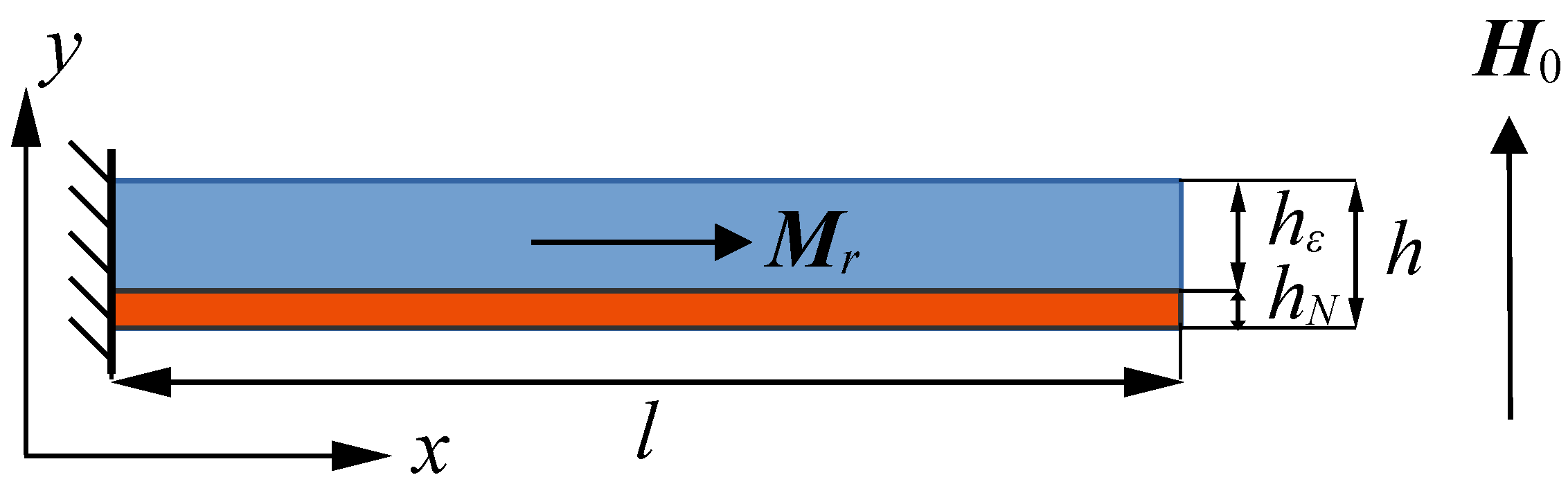
Consider a cantilever (bi-layer plate) composed of titanium nickelide and a magnetoactive elastomer containing magnetically hard NdFeB particles. The cross-section of such a plate is shown in
Figure 1, with titanium nickelide shaded in red and the magnetoactive elastomer in blue. It is assumed that adhesion between the two layers is perfect (the displacement field is continuous). The plate has a length
l (dimension along the
x-axis) and a thickness
h (dimension along the
y-axis), with the titanium nickelide layer thickness denoted by
and the magnetoactive elastomer layer thickness denoted by
(
). The plate is clamped at the left edge, while the other surfaces are free. Initially, the titanium nickelide layer is in the austenitic (high-temperature) state, and the magnetoactive elastomer has a residual magnetization
, directed along the
x-axis. An external magnetic field
, directed along the
y-axis, is applied to this sample, after which it is cooled to the martensitic (low-temperature) state of titanium nickelide, and the magnetic field is removed.
To model the behavior of this bi-layer plate in the approximation of small deformations, the basic relations for the titanium nickelide layer and the magnetoactive elastomer are formulated, neglecting thermal deformations due to their minimal influence. During the cooling process, phase transformations will induce phase strains in the titanium nickelide that disappear upon subsequent heating. In the framework of small deformations, the additivity of elastic and phase strains is assumed.
2.1. Basic Relations for Titanium Nickelide
To describe the phase transition in shape memory alloys (SMAs), a scalar internal variable
is introduced, representing the volume fraction of the martensitic phase in the material. This variable ranges from 0 in the fully austenitic (high-temperature) state to 1 in the fully martensitic (low-temperature) state. For a forward phase transition (austenite to martensite), the inequality
is valid, while for the reverse transition (martensite to austenite),
is satisfied. The phase transition diagram (the dependence of the martensitic phase fraction
on temperature
) is approximated by the following relation (see, e.g., [
22]):
where
Here,
, and
are the start and finish temperatures of the forward and reverse martensitic transformations in the stress-free material, while
, and
are the start and finish temperatures of these transformations in the stressed material. Note that forward and reverse phase transitions occur at different temperatures: the temperature range
corresponds to the austenite-to-martensite transition, while
corresponds to the martensite-to-austenite transition.
For a stressed material, the critical transition temperatures are given by the following linear dependence on the stress intensity
:
where
is a material constant.
According to [
24], the equations describing the evolution of phase strains are written as follows:
Here,
and
are material parameters;
is the unit tensor;
and
are the phase strain increment and current phase strain;
and
are the martensitic phase parameter and phase strain values at the initial point of the reverse transformation process; and
is the deviator of the stress tensor
.
The elastic behavior of titanium nickelide is described by Hooke’s law [
25,
26]:
where
and
are the Lamé parameter and the shear modulus of titanium nickelide (their values change during the phase transition);
is the elastic strain tensor;
is the total strain tensor; and
is the first invariant of
.
The dependencies of the elastic properties of the material (Young’s modulus
and shear modulus
) on the martensitic phase fraction
are defined by the following relations:
where
and
are the values of Young’s modulus and shear modulus for the martensitic state, and
and
are the same values for the austenitic state. Hence, we obtain that
2.2. Basic Relations for Magnetoactive Elastomer
The elastic behavior of the magnetoactive elastomer is also described by Hooke’s law:
where
and
are the Lamé parameter and the shear modulus of the magnetoactive elastomer, and the elastic strains are equal to the total strains (
).
In the material under a magnetic field, a mass moment arises, where is the magnetic constant. To simplify the model and avoid solving the magnetostatic problem, we set , so . We assume that the residual magnetization is uniform, constant, and directed along the cantilever axis, since small magnetic fields are considered and NdFeB particles have large anisotropy.
2.3. Variational Formulation of the Problem
For the numerical solution of the boundary value problem, we present its variational formulation in the Lagrangian form, where the variable quantity is the displacement
. To account for geometric nonlinearity, the strain tensor is defined as follows:
To account for the rotation of the remanent magnetization vector
during bending of the plate, we introduce the rotation tensor
as follows:
so that the magnetization after bending equals
.
Let
and
represent the regions occupied by titanium nickelide and the magnetoactive elastomer, respectively. The variational equation is written as follows:
This equation can be rewritten in dimensionless form:
where the following dimensionless quantities are introduced:
2.4. Numerical Solution
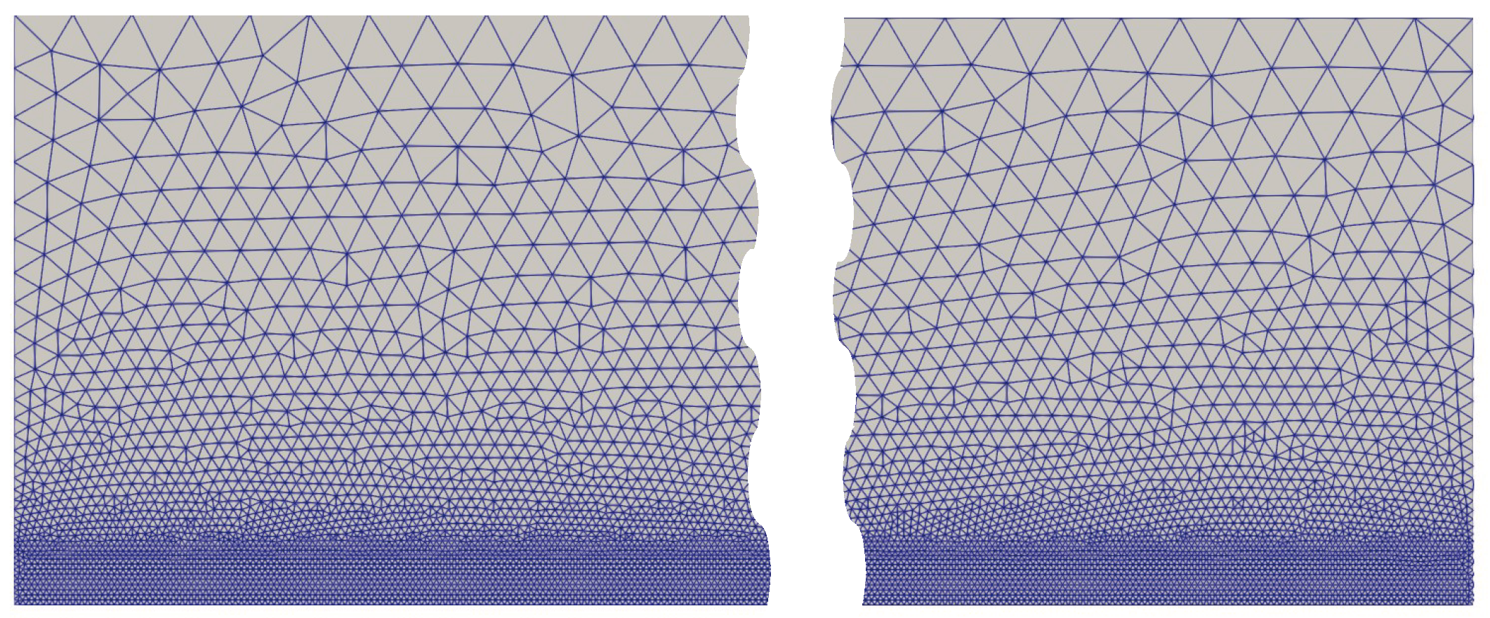
The problem was solved numerically by the finite element method, implemented using an open computing platform for solving partial differential equations FEniCS [
27]. The mesh covering the computational domain (the fragments of which are shown in
Figure 2) consists of triangular elements and is generated automatically with specified parameters (with refinement near the titanium nickelide region—the lower part of the sample) using the gmsh package [
28]. A linear approximation of the displacement vector
was used.
To solve the variational problem (
8), it is necessary to know the phase strains
. Since Equations (
3) and (4) are written for the increment of phase strains, the problem is solved using the step-by-step loading method: the entire cooling or heating process is divided into a series of small temperature steps, and at each step, the increment of the martensitic phase fraction and the phase strain increment are calculated. The total phase strains at each step are computed as the sum of the accumulated phase strains and the phase strain increment. The nonlinear variational equation (due to geometric nonlinearity) was solved by Newton’s method using the FEniCS computing platform.
3. Results
For numerical simulation, the following parameter values were used for titanium nickelide (NiTi):
Elastic moduli in the austenitic and martensitic states , , and Poisson’s ratio ;
Temperatures for the start and finish of direct and reverse martensitic transformations K, K, K, and K (in our calculations, we do not account for the dependence of the critical transformation temperatures on material stresses);
Material parameters associated with phase strain accumulation , , , and ;
Further, we use the following parameter values for the magnetoactive elastomer:
For numerical calculations, the plate length was set to be 10 times its thickness ().
Figure 3 shows the loading diagram of the bi-layer plate: during the first
k steps, the magnetic field increases from
to
at a constant temperature
K, corresponding to the austenitic state of titanium nickelide; over the next
k steps, the temperature decreases to
K, corresponding to the martensitic state of titanium nickelide, under a constant magnetic field of
. Over the final
k steps, the magnetic field is reduced to
at a constant temperature of
K. Thus, the plate remains in the martensitic state with accumulated strains from the phase transition, while the external magnetic field is absent.
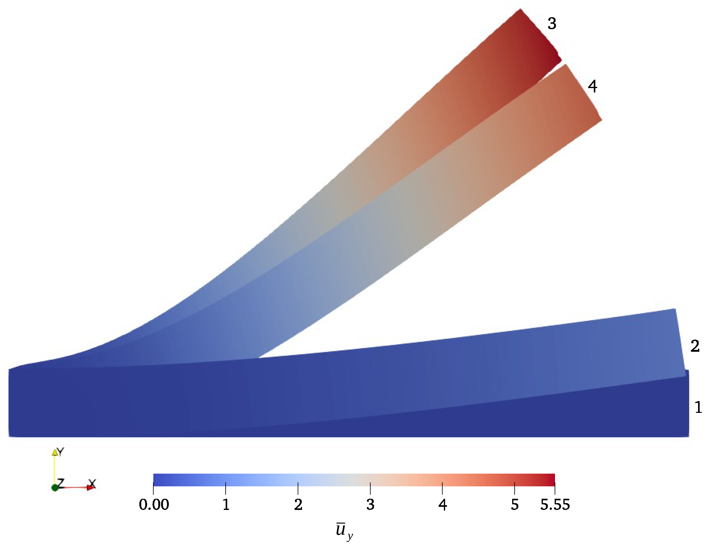
Figure 4 shows the following configurations of the plate: 1—initial configuration, 2—after application of the magnetic field, 3—after cooling under a constant magnetic field, and 4—after removal of the magnetic field (this configuration is determined by phase strains arising in titanium nickelide during the direct phase transition upon cooling). The color shows the distribution of the displacement vector component
. These configurations were obtained for a titanium nickelide layer thickness of
.
When a magnetic field is applied along the
y axis, the residual magnetization vector in the magnetoactive elastomer aligns with this field, causing the plate to bend and resulting in stress throughout the plate (in both the magnetoactive elastomer and titanium nickelide).
Figure 5a shows the stress intensity distribution in the left part of the sample (maximum stresses occur closer to the fixed area). The phase strains arising in the titanium nickelide layer during cooling are proportional to the stresses.
Figure 5b shows the axial component distribution of the phase strain tensor in the left part of the sample, with a maximum strain value of
. These strains determine the plate’s bend magnitude after the magnetic field is removed. Note that if the plate is heated to a temperature at which titanium nickelide is in the austenitic state, the phase strains will completely disappear during the reverse phase transition and the sample will return to the initial configuration (configuration 1 in
Figure 4).
It is evident that the plate’s deflection magnitude (displacement of the right end
of the cantilever) will depend on the thickness of the titanium nickelide layer
.
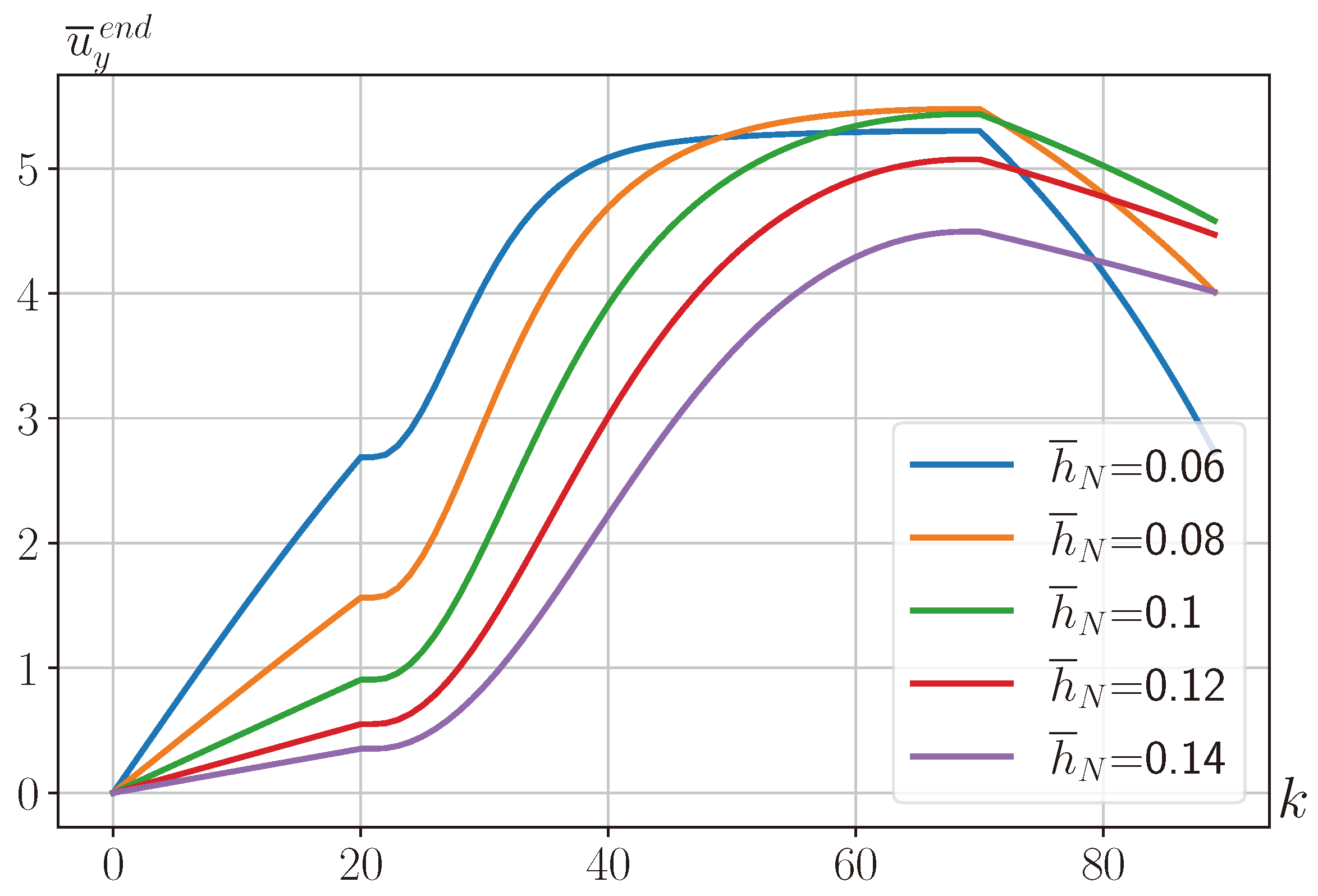
Figure 6 shows the dependence of the deflection magnitude
on step number
k, corresponding to
Figure 3, at various values of titanium nickelide layer thickness
.
Figure 6 shows that the maximum deflection after plate cooling and after removal of the external magnetic field occurs at different titanium nickelide layer thicknesses
, and these dependencies are generally non-monotonic.
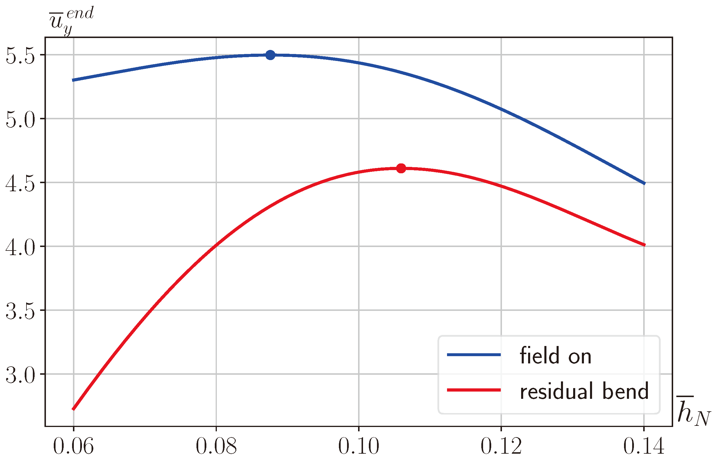
Figure 7 shows curves (deflection in the magnetic field—blue curve; deflection after the magnetic field is removed—red curve) from which one can find the values of
corresponding to maximum deflection in the magnetic field
. For this field, the maximum free end displacement magnitude is
at a titanium nickelide layer thickness of
in the magnetic field and
at a titanium nickelide layer thickness of
after the magnetic field is turned off. Thus, the thickness of the titanium nickelide layer can be selected to achieve the required residual plate deflection.
The deflection magnitude of the bi-layer plate will depend not only on the thickness of the titanium nickelide layer but also on the magnitude of the magnetic field applied during the plate’s bending.
Figure 8 shows the dependence of the deflection magnitude (deflection in the magnetic field—blue curve; deflection after the magnetic field is removed—red curve) on the magnitude of the applied magnetic field at a titanium nickelide layer thickness of
. From this figure, it can be seen that an increase in the magnetic field leads to an increase in the deflection, and this dependence is nonlinear. Using these dependencies, the magnetic field magnitude necessary to achieve a specified residual plate deflection can be determined. The difference between the displacement of the cantilever’s free end before and after the magnetic field is removed also increases with an increase in the applied magnetic field.
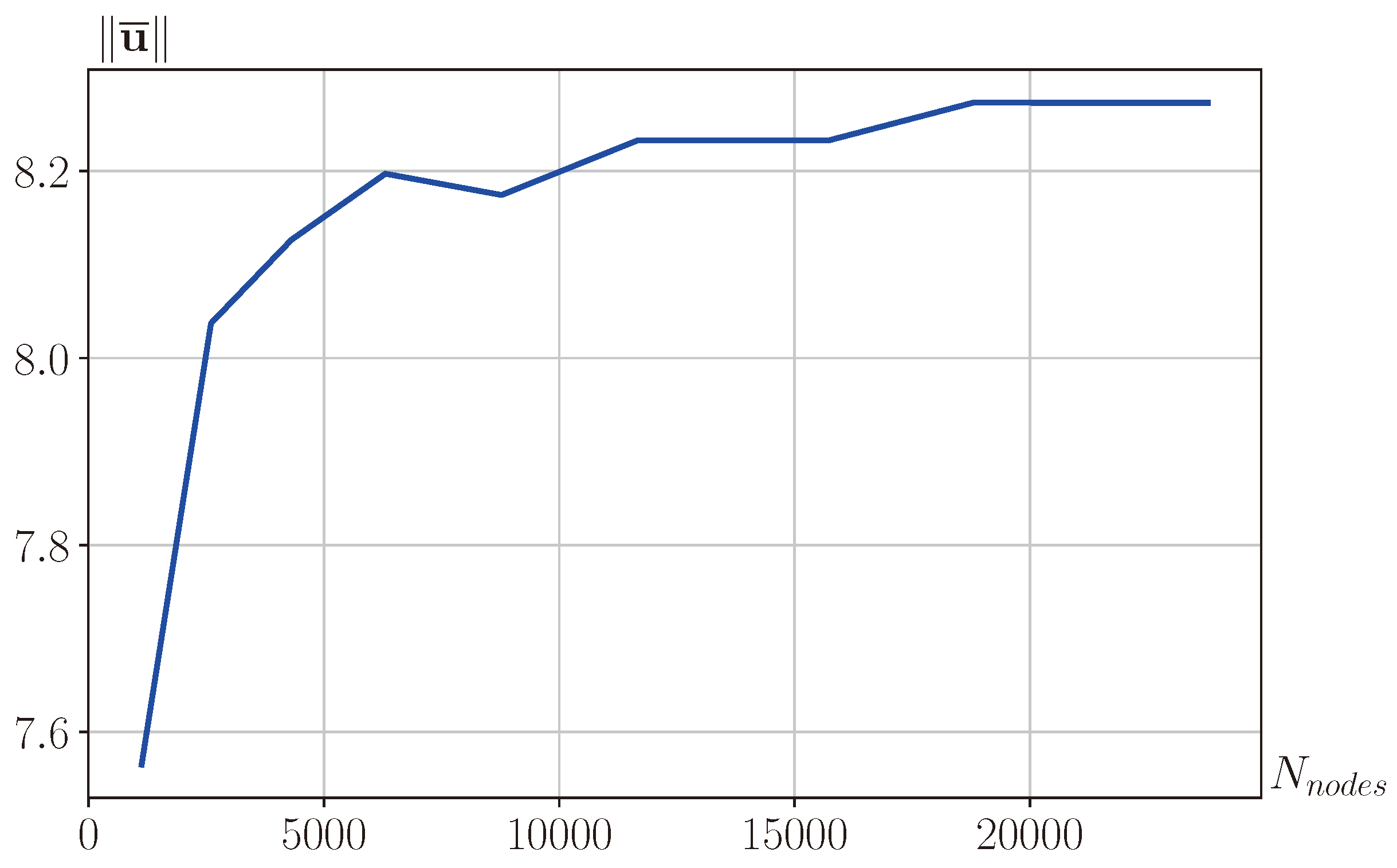
To check the convergence of the numerical method, we present a convergence plot for a series of numerical calculations with different numbers of mesh nodes.
Figure 9 shows the dependence of the displacement vector norm
on the number of mesh nodes
. This displacement is at the end point of the process under consideration (after removing the magnetic field). The ratio of the element sizes in the upper and lower parts remained 1 to 10. It is evident from the figure that with an increase in the number of nodes, the numerical solution reaches a constant value, which shows the convergence of the method.
4. Discussion
This study models the behavior of a cantilever (a bi-layer plate) composed of titanium nickelide (NiTi) and a magnetoactive elastomer containing magnetically hard NdFeB particles. The preliminary deflection is set as follows: in the high-temperature state (austenitic) for titanium nickelide, an external magnetic field is applied perpendicular to the cantilever axis (and the residual magnetization vector in the MAE layer); then, the sample is cooled in such a way that a direct phase transition occurs in the titanium nickelide layer, after which the magnetic field is removed in the low-temperature state. It should be noted that titanium nickelide is in the martensitic state at room temperature. By switching the magnetic field on and off, the position of the cantilever’s free end can be controlled.
The influence of the applied magnetic field magnitude and the thickness of the titanium nickelide layer on the cantilever deflection was investigated. The optimal NiTi layer thickness, which maximizes deflection (both before and after magnetic field removal), was identified. The dependence of the residual cantilever deflection on the lied magnetic field was obtained.
In order to understand whether it is possible to bend a real sample with a magnetic field, it is necessary to estimate the concentration of magnetically hard particles. For this, let us set MPa, which corresponds to realistic values for existing magnetoactive elastomers (MREs). Then, kA/m. Given that the saturation magnetization of NdFeB particles is about 800 kA/m, this results in an approximate volume concentration of 30%. The dimensional value of the magnetic field is kA/m, which corresponds to moderate laboratory field strengths.
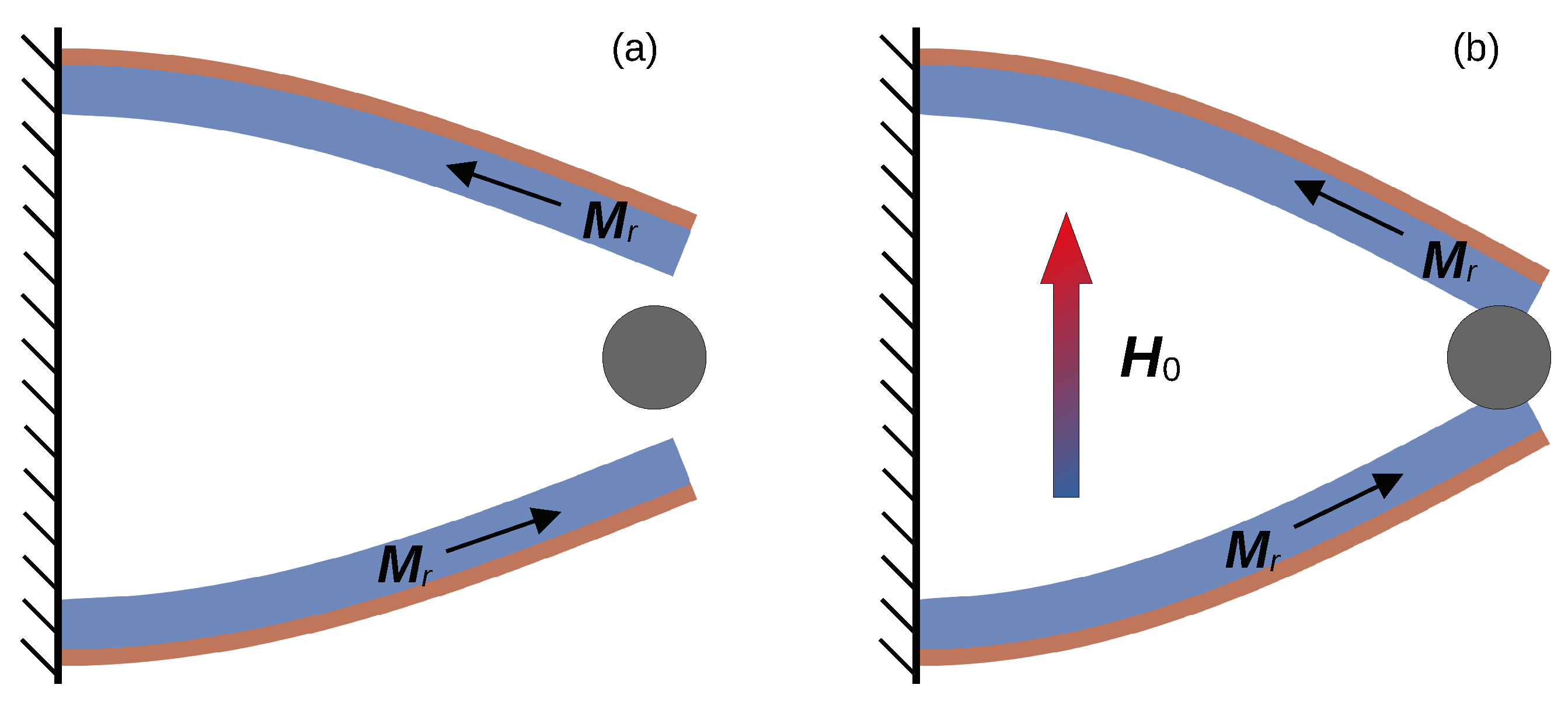
The results of this study make it possible to calculate the bi-layer cantilever’s operation as an actuator, which can, for example, perform object gripping upon application of a magnetic field (when using two cantilevers). The required magnetic field strength to achieve a specified deflection can be determined (a preliminary deflection of the grip is created by applying a magnetic field in a high-temperature state, cooling to a low-temperature state, and then turning off the magnetic field), and the working displacement of the grip, defined by the difference in free-end movement before and after magnetic field removal, can be calculated.
Figure 10 shows the working mechanism of such a gripper, consisting of a pair of bi-layer cantilevers with inner MAE layers and outer NiTi layers. In
Figure 10a, the elements’ position in the absence of a magnetic field is shown, while
Figure 10b illustrates the position when the magnetic field is applied.
Let us estimate the force that the gripper can implement when a magnetic field is applied. Here, we will not solve the contact problem in its full formulation; instead, after obtaining the preliminary deflection of the cantilever, we will assume that the boundary of the gripped object of length coincides with the boundary of the cantilever and is located on the right edge (in the numerical calculation, displacements in the contact area are fixed). After applying the magnetic field, we integrate the stresses over the contact area and find the force. For cm and kA/m, we obtain a force N.
We also note that the cantilever could be a critical component in the following:
Soft robotics: acts as a flexible gripper for fragile objects with variable stiffness, allowing for adaptive control.
Medical devices: supports minimally invasive instruments that require precise manipulation in confined spaces, such as endoscopic actuators.
Variable stiffness actuators: uses dual-stimulus control for complex programmable deformation profiles.
These examples highlight the versatility and practical relevance of the research.
The model presented in this study is relatively simple, yet it effectively describes the operation of the bi-layer cantilever. In the future, this model will be extended by defining constitutive relations within the framework of finite deformations. Additionally, a contact problem will be formulated and solved to simulate the operation of a gripper using a bi-layer cantilever as its element.


