Article

Computational Modelling of Intra-Module Connections and Their Influence on the Robustness of a Steel Corner-Supported Volumetric Module

1
Modern Methods of Construction Research Group, School of Civil Engineering, University College Dublin, Belfield, Dublin 4, D04 V1W8 Dublin, Ireland
2
MJH Structural Engineers, Suite 3 Anglesea House, 63 Carysfort Avenue, Blackrock, Co., A94 X209 Dublin, Ireland
*
Author to whom correspondence should be addressed.
Modelling 2024, 5(1), 392-409; https://doi.org/10.3390/modelling5010021
Submission received: 10 January 2024 / Revised: 4 March 2024 / Accepted: 19 March 2024 / Published: 21 March 2024

Abstract

:
This paper investigates the robustness of a single 3D volumetric corner-supported module made of square hollow-section (SHS) columns. Typically, the moment–rotation (M-θ) behaviour of connections within the module (intra-module) is assumed to be fully rigid rather than semi-rigid, resulting in inaccurate assessment (i.e., overestimated vertical stiffness) during extreme loading events, such as progressive collapse. The intra-module connections are not capable of rigidly transferring the moment from the beams to the SHS columns. In this paper, a computationally intensive shell element model (SEM) of the module frame is created. The M-θ relationship of the intra-module connections in the SEM is firstly validated against test results by others and then replicated in a new simplified phenomenological beam element model (BEM), using nonlinear spring elements to capture the M-θ relationship. Comparing the structural behaviour of the SEM and BEM, under notional support removal, shows that the proposed BEM with semi-rigid connections (SR-BEM) agrees well with the validated SEM and requires substantially lower modelling time (98.7% lower) and computational effort (97.4% less RAM). When compared to a BEM with the typically modelled fully rigid intra-module connections (FR-BEM), the vertical displacement in the SR-BEM is at least 16% higher. The results demonstrate the importance of an accurate assessment of framing rotational stiffness and the benefits of a computationally efficient model.

Graphical Abstract

1. Introduction

In many countries, there exists a housing supply deficit [1], in which traditional methods of construction, e.g., masonry construction, are unable to achieve the required housing targets [2]. In addition to housing supply issues, efficient use of materials and reducing construction-related CO2 and construction waste are needed to help achieve ambitious climate change targets, e.g., the European Green Deal [3]. Modular and offsite construction are forms of Modern Methods of Construction (MMC) that offer a wide range of benefits through the application of the Design for Manufacture and Assembly approach when compared to its traditional counterparts [2,4,5]. The main benefits of modular construction compared to traditional construction include shorter project delivery time, better quality control, less site wastage, fewer site-related injuries, and less construction noise [6]. Concerning climate change, modular construction could reduce carbon emissions by up to 45% when compared to some traditional practices [7]. Therefore, it is important to be able to utilise MMC in order to achieve housing targets, as well as reduce the impact of construction on the environment. Figure 1 shows two recent high-rise modular projects in Croydon, UK, in which some of the authors participated as structural engineers. The building in Figure 1a comprises two towers of 38 and 44 storeys, while the building in Figure 1b similarly comprises two towers of 35 and 49 storeys.
There are two primary types of steel modular systems used in medium- to high-rise buildings, namely, corner-supported modules (Figure 2a) and wall-bearing modules (Figure 2b). This paper will focus on modular steel buildings (MSBs) constructed with corner-supported modules where the vertical loads are resisted through the corner columns (i.e., similar to those used in the projects shown in Figure 1). A more comprehensive review of modular construction covering different aspects may be obtained in [6,10,11]. Despite its numerous advantages, the uptake of modular construction is still low relative to more traditional methods of construction [12]. Part of the reason is a lack of understanding of their structural behaviour and robustness. The main reason for this is that no standardised design approach exists, and no industry-accepted connections and design guidelines for this relatively new construction technique exist [11,13].
Several recent studies have attempted to better understand the overall structural behaviour and robustness of corner-supported MSBs [14,15,16,17,18,19,20,21]. Alembagheri et al. [15] investigated the role of inter-module connections (i.e., connections between modules) in the robustness of corner-supported MSBs by notionally removing a complete modular unit to simulate the loss of supports. To focus primarily on the inter-module connections, the modules were modelled as a solid block (i.e., macro model). However, modelling a whole module as a solid block ignores the potential that structural components within the modules could fail before the inter-module connections and does not allow for redistribution of forces within the module due to bending/shear/distortion of individual structural members. The importance of modelling structural components within the module was illustrated by Luo et al. [18] in a parametric analysis to study the robustness of corner-supported MSB using a beam element model (BEM). It was found that progressive collapse was triggered by excessive buckling deformation in the columns close to the removed column following a redistribution of loads. However, the intra-module connections (i.e., connections within the modules) were assumed to be fully rigid as connections were assumed to be welded. This assumption neglected any localised behaviour in the connection between the beam and the column. Chua et al. [16] investigated the robustness of a 40-storey high-rise corner-supported MSB laterally braced with a central concrete core. Under the corner column removal scenario, it was demonstrated that the high-rise corner-supported MSB was capable of preventing progressive collapse due to the high intrinsic structural redundancies in the system. Although no collapse was observed upon the removal of a corner column, the use of fully rigid beam-to-column connections in the BEM could have altered the actual load redistribution mechanism and may have overestimated the robustness of the building. Lawson and Richards [17] investigated the inter-module connection tie-force needed to achieve equilibrium in a single corner-supported module with the support to one corner column removed. The analysis shows that the actual tie force required was lower than that calculated using BS 5950-1 [22], with a marginal vertical displacement of 32 mm (relative to the size of the module: 3.6 m (W) × 7.2 m (L) × 2.7 m (H)) at the unsupported column. However, fully rigid header- and beam-to-column connections were adopted in the BEM, and, therefore, the results might not have reflected the actual vertical displacement at the unsupported column and tie force in the connections. This is because a less stiff joint (semi-rigid rather than rigid) could increase the module vertical displacement at the unsupported location, as well as the internal members and connections tie force. Swami et al. [19] numerically investigated the robustness of a 10-storey composite MSB with fully rigid connections in corner-supported modules utilising concrete-filled steel tube column and found that the dynamic amplification factor (DAF) of 2.0 suggested by GSA [23] overestimated the dynamic response of the building investigated. In the analysis [19], only the semi-rigidity of inter-module connections has been considered; however, the intra-module connections were assumed to be fully rigid. The role of intra-module connections was highlighted by Peng et al. [21] in a progressive collapse analysis of a multi-storey corner-supported MSB modelled using a combination of finite shell and solid elements. The fracture of the intra-module connections was identified as one of the governing failure mechanisms causing collapse. However, analysing a full building using finite shells and solid elements can be computationally expensive and may be difficult to implement in daily engineering practice. A series of parametric push-down analyses by Shan and Pan [20] on a six-storey corner-supported MSB showed that the residual capacity (i.e., overstrength factor) of the building, with the corner module removed, increased with the section size of the columns (i.e., axial capacity). However, some of the columns considered had a very slender cross-section (i.e., Class 4 cross-section as per BS EN1993-1-1 [24]) and were prone to local buckling before attaining their global buckling capacity. Nonetheless, this was not accounted for in the results due to the limitation of the finite beam element used in that study, which was unable to capture local buckling.
Most of the studies to date investigating the structural robustness of corner-supported MSBs have focused on the effect of inter-module connections (i.e., connections between the modules) while assuming that the intra-module connections were fully rigid. However, in corner-supported MSBs where hollow section columns are often used [6,16,17,18,19,20,21,25,26], the welded connections between the beams and columns may not be fully rigid despite the connections being welded. The reason for this is that the face of the hollow section columns where the beam is connected may deform locally when subjected to an end moment from the beams under floor loadings [27,28,29]. The local flexibility of the column face can lead to additional second-order effects that could adversely affect the robustness of corner-supported MSBs. Therefore, modelling the welded connections in the modules as fully rigid in conventional BEMs could overestimate the actual stiffness of a corner-supported MSB. One solution to this could be using shell element models (SEMs) to model the structural behaviours as they can capture local deformation effects. However, analysing a full building using an SEM requires substantial computational effort.
To account for the shortcomings in conventional fully rigid BEMs (FR-BEMs), a new phenomenological semi-rigid BEM (SR-BEM) for a single corner-supported module is developed in this paper. The semi-rigidity (M-θ) of the intra-module connections is captured via nonlinear rotational spring elements (zero length). The connections of the semi-rigid M-θ relationship were obtained by matching their behaviour to a validated SEM (i.e., one entire module). The SEM was validated against welded beam-to-column joints from test data by Havula et al. [28]. The validation showed good agreement between the SEM analysis, experiment data [28], and SR-BEM. Subsequently, the performance of the SR-BEM and SEM under a progressive collapse loading scenario (i.e., notional support removal) was compared and showed good agreement. Additionally, the SR-BEM is 98.7% and 97.4% more computationally efficient, respectively, in terms of time and effort (minimum RAM required) than the SEM. Finally, the new phenomenological BEM (i.e., SR-BEM) was loaded with four different load cases (service, ultimate, accidental, and equivalent static accidental loads), and the resulting vertical deflection of the unsupported column was compared with a conventional FR-BEM. At least 16% additional vertical displacement was observed in the proposed SR-BEM when compared to FR-BEM (i.e., industry norm). Also, a 22% lower and 16% higher horizontal support reaction (i.e., tie force) was observed in the short wall support and long wall support, respectively, of the SR-BEM compared to the FR-BEM.

2. Materials and Methods

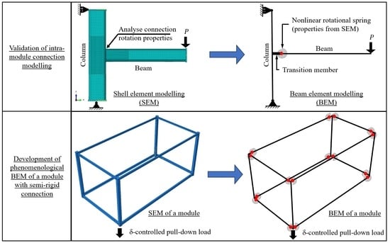
2.1. Modelling Strategy

In this paper, a single 3D module frame was numerically investigated separately using shell and beam modelling approaches in ABAQUS [30]. The SEM of the 3D module frame is shown in Figure 3. Details of the material model, SR-BEM, and SEM models are described later in this section. The modelling process to arrive at an accurate and efficient phenomenological SR-BEM is as follows:
  • Validate computationally intensive SEM to existing test data for the typical intra-module connection;
  • Develop computationally efficient and accurate semi-rigid BEM (SR-BEM) that is calibrated against the validated SEM and captures the moment–rotation behaviour of the connections;
  • Model the entire module using fully rigid connections (FR-BEM) and compare its structural response to the SR-BEM.

2.1.1. Connection Moment–Rotation Validation of SEM

For validation purposes, a welded header-to-column joint experimentally investigated by Havula et al. [28] was modelled and analysed numerically. The experiment [28] investigated the M-θ relationship of several welded tubular beam–column joints using different combinations of weld throat thicknesses, steel grades, and section sizes. The experiment for a 150 × 150 × 8 SHS column with a 100 × 100 × 8 SHS beam welded to the mid-height of the column using an 8.48 mm fillet weld (i.e., 6 mm throat) was chosen for validation purposes in this paper as it matched a typical intra-module connection very well. These were the same sections used in the frame model in this paper (Figure 3). Both the beam and column were 700 mm long, and the steel grade was S420, with a stress–strain relationship from a coupon test provided by the author of [28] (Note: it was necessary to contact the authors of [28] directly to obtain the coupon test results).
The connection between the header and column in the SEM is shown in Figure 4. The top and bottom of the column were pin-supported, with the top having been allowed to move vertically. All extremities of the members in the SEM were restrained from out-of-plane movement, therefore capturing the in-plane connection M-θ response only. All the components were meshed with ABAQUS S4R shell elements [30]. S4R is a linear 4-noded quadrilateral SHELL element with reduced integration points [30]. To improve the analysis efficiency of the SEM, a finer mesh was considered at locations where high-stress concentrations were observed in preliminary analysis (e.g., where beam and column are welded) while other parts had a coarser mesh (i.e., twice the size of fine mesh), as shown in Figure 4. The area with the fine mesh extended 300 mm from the point of intersections of all the structural components (see Figure 4). The mesh refinement analysis has been performed for the tubular beam–column joint shown in Figure 4, from which a 5 mm square mesh at the finer mesh zone was deemed sufficient to capture the local effects. Figure 5 shows the M-θ relationship for a model of different mesh densities. The mesh sizes noted in Figure 5 are those for the fine mesh zone, and the size of the coarse mesh is double the value noted, with the exception of the 20 mm mesh, where 20 mm mesh was used throughout. From Figure 5, it can be observed that 10 mm and 20 mm square meshes are stiffer than 2.5 mm and 5 mm square meshes. In Figure 6, the von Mises stress contour and failure mode for each model of different mesh densities at approximately 0.2 rad rotation θ are illustrated. It can be observed that for the model with 2.5 mm square mesh (Figure 6a), failure occurs much earlier, with tearing observed at the column face in addition to the side wall crushing. Side-wall crushing was observed in all other meshes. The stress contour plot is discontinuous at the transition between fine and coarse mesh in the 10 mm (Figure 6c) and 20 mm square mesh models (Figure 6d), indicating inadequate refinement of mesh. The peak stress was very similar at 0.2 rad rotation θ for all four meshes (minimal difference for 20 mm), as can be seen in the stress legends. Upon comparing the M-θ relationship for a model of different mesh densities to the test results by Havula et al. [28], the 5 mm square mesh (Figure 6b) better modelled the hardening behaviour, as shown in Figure 7. For the 5 mm mesh, the theoretical estimation for yield moment is 20 kNm, while numerical estimation is approximately 21 kNm, representing a 5% error. As can be seen from Figure 7, the SEM with a 5 mm square mesh captures the test results with good accuracy, up to approximately 0.2 rad rotation. The peak moment observed in the test was 34.6 kNm at 0.271 rad compared to 32.3 kNm at 0.266 rad observed in the analysis (i.e., approximately 6.6% lower). Therefore, the 5 mm square mesh was selected for the SEM.

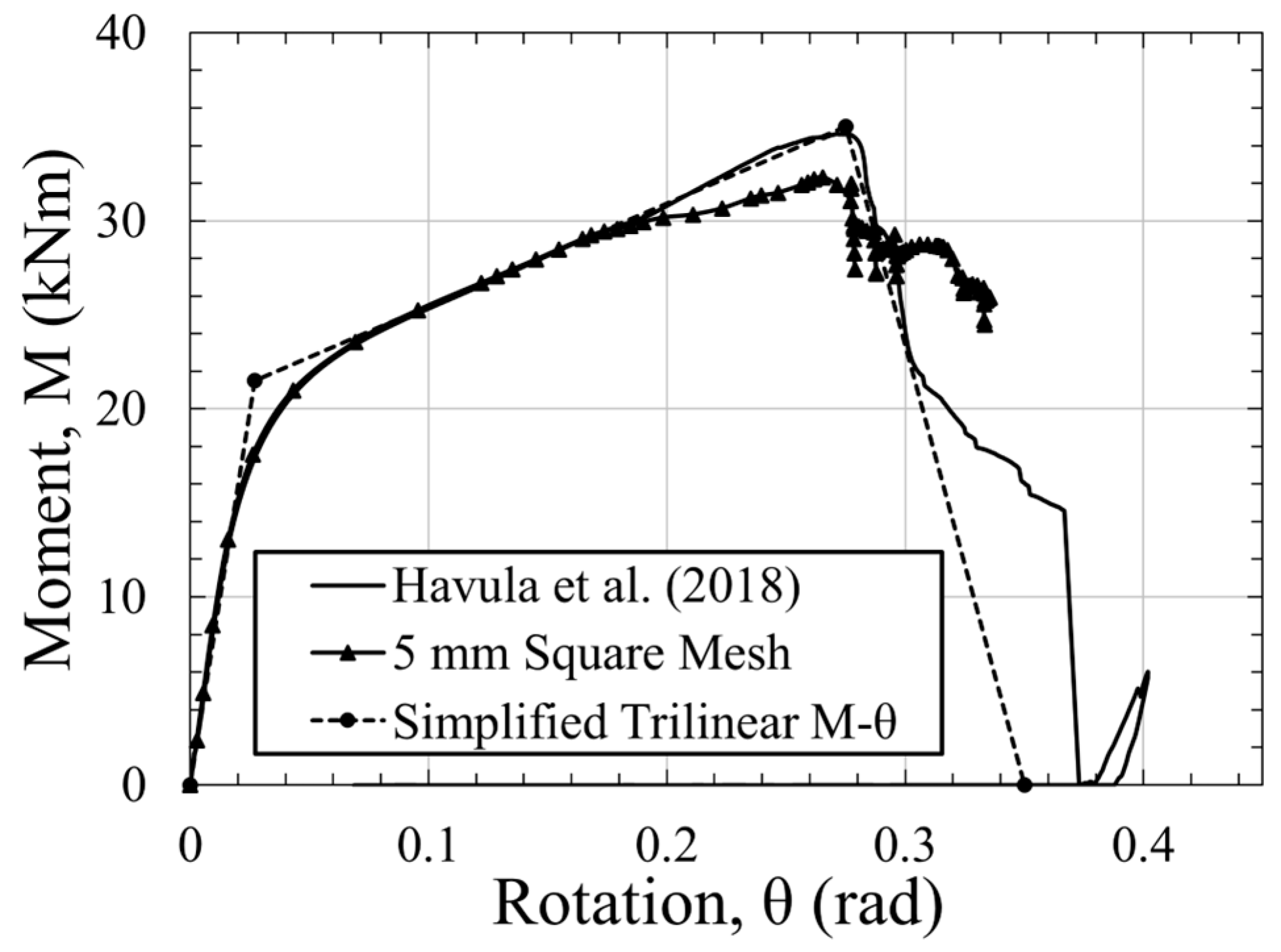
2.1.2. Moment–Rotation Calibration of SR-BEM

The schematic of the SR-BEM connection between the header and column is shown in Figure 8. This model exactly matches the geometry of the SEM shown in Figure 4, which has been validated against experimental data. For the SR-BEM, all the closed sections (i.e., SHS) were meshed with ABAQUS beam element B32. The B32 element is a 3-noded quadratic beam element. The column was discretised with two beam elements, while the beam was discretised with one element. To account for the effect of eccentricity in the joint, a 75 mm rigid beam was modelled in the SR-BEM before connecting to the beam via a nonlinear rotational spring, as shown in Figure 8. The SR-BEM uses beam elements in 3D space; however, it only captures in-plane M-θ behaviour as all out-of-plane displacements have been restrained.
Using the results obtained in the SEM, a simplified trilinear M-θ relationship of the joint (Figure 4) was approximated using the method proposed by Grotmann and Sedlacek [27], as shown in Figure 7. The simplified trilinear M-θ relationship was then assigned to a nonlinear rotational spring connecting the rigid beam-to-beam in the SR-BEM. Under the same loading regime as the SEM, an M-θ relationship for the SR-BEM was obtained and illustrated in Figure 9. Similar to the SEM, this SR-BEM was in good agreement with that obtained in the experiment by Havula et al. [28] up to the ultimate load. In the post-peak range, some discrepancies were observed.

2.2. Framed Module Model

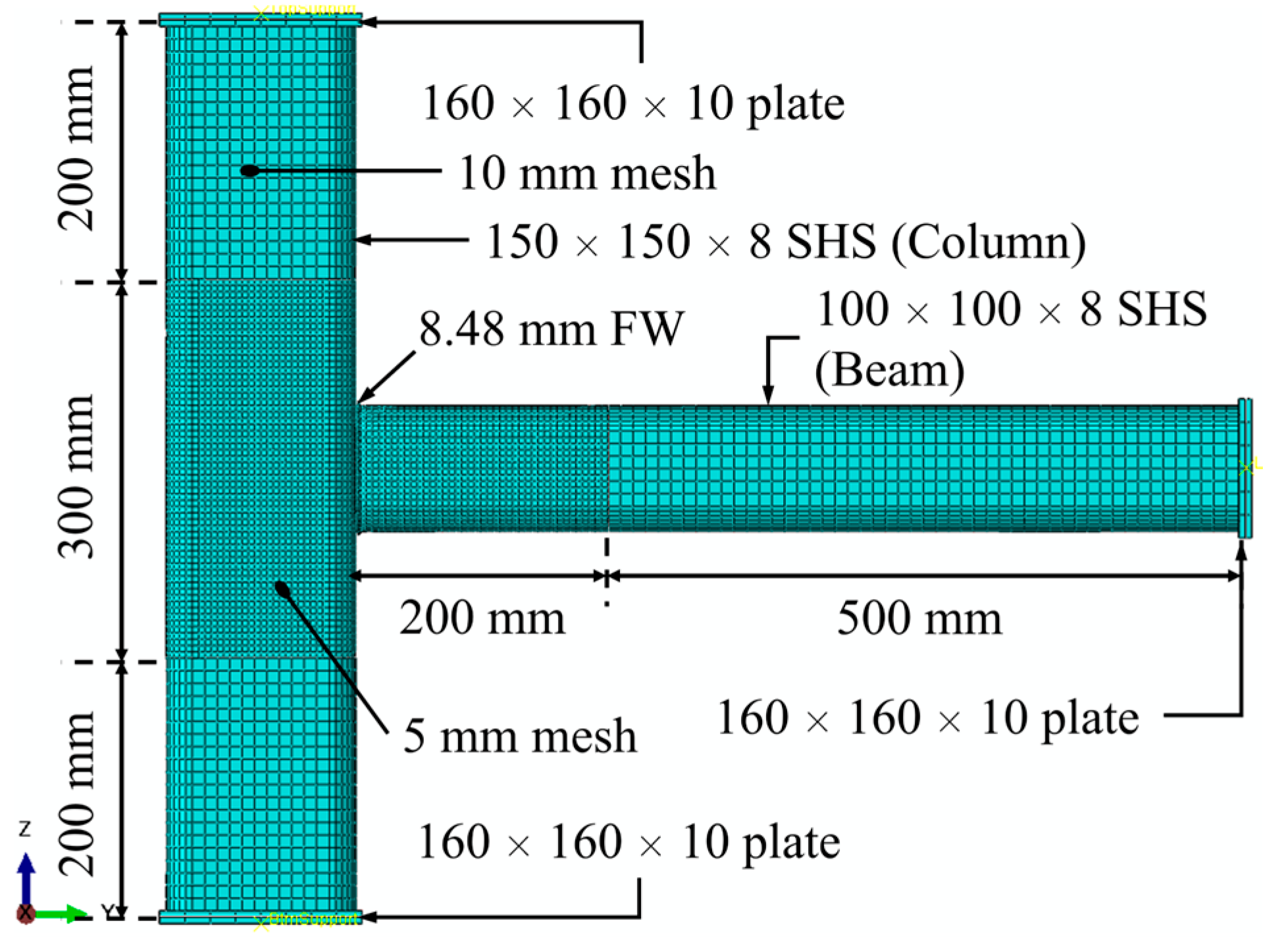
2.2.1. Details of the Module

The framework of a corner-supported steel module is typically made of steel members such as square or rectangular hollow section (SHS/RHS) columns and parallel flange channel (PFC) or RHS beams [13,32,33], as shown in Figure 3. The dimensions of the module selected for analyses herein are 6.3 m (L) × 3.3 m (W) × 3.05 m (H), which is a common size for corner-supported modules made of four corner columns with peripheral headers and beams welded to top and bottom of the corner columns [6]. In this paper, a module frame made from four corner 150 × 150 × 8 SHS columns (with Class 1 cross-section as per BS EN 1993-1-1 [24]), 100 × 100 × 8 SHS header, and 150 × 75 × 18 UKPFC welded to the top and bottom of the corner columns, respectively, forming a self-stabilised 3D frame was modelled, as shown in Figure 3. In the SEM, all the columns have a 25 mm thick end plate welded to either end as a standard practice to keep the columns’ ends flush. Additionally, in each of the two long walls, two diagonal braces (100 × 50 × 3 RHS) were welded to the beam at approximately one-third span to improve serviceability limit state performance of the module. In relation to the boundary conditions, the 3D module frame was pin-supported at three corners (Corner A, C, and E in Figure 3), leaving the remaining column (Corner G) unsupported for a displacement-controlled pull-down load. The direction of the red arrows shown in Figure 3 indicates the reaction forces resulting from the pin supports in that direction. All structural members in the SEM were assumed to be connected using full penetration butt welds (FPBW) and modelled using the tie constraint in ABAQUS [30]. A tie constraint was used to simulate the welding between two surfaces by allowing for no relative motion between the tied surfaces.

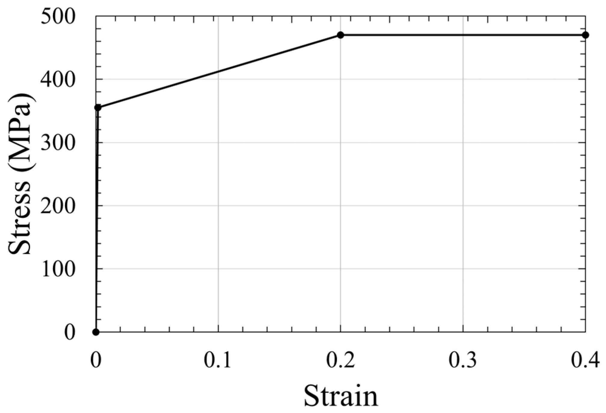
2.2.2. Material Model

Typically, the steel grade used in modular construction is S355 rather than S420, as used in the validation model. The reason was that the use of S420 steel in modular construction would result in an uneconomical structural design due to the high residual capacity of the structure members. The S355 grade steel with a nominal stress–strain curve defined as per Clause C.6 of BS EN1993-1-5 [34] was used in this paper. The stress–strain curve defined in this model is shown in Figure 10, with a nominal yield strength of 355 MPa as per BS EN1993-1-1 [24]. For the ultimate strength and strain, the minimum requirements for hot-rolled S355 structural steels were conservatively adopted as per Table 6 of BS EN10025-2 [35] (not included in this publication). The ultimate strength adopted was 470 MPa, with an ultimate total strain of 20%. Beyond the ultimate total strain limit, perfectly plastic behaviour was assumed.

2.2.3. SR-BEM of Module

In the SR-BEM of the entire module, all the structural components were meshed with the B32 beam element except the PFC (an open section susceptible to warping), which was meshed with the B32OS beam element [30]. The only difference between the B32 (used in the header-to-column connection analysis in Section 2.1.2) and the B32OS beam element is the B32OS has an additional warping degree of freedom at its end nodes. All the beams and headers were meshed with one element except for the columns and diagonal bracings, where two elements were used. The use of two B32 elements creates a mid-height node close to the middle of the compression members, which allows for the buckling to occur [36]. A numerical analysis conducted by Heng et al. [31] demonstrated that a column discretised with 2 elements and a H/1000 initial out-of-plane displacement (H is the height of the column) applied to the mid-point node captures the nonlinear buckling behaviour of the column with good accuracy. The bilinear M-θ relationship obtained in Section 2.1.1 for the PFC beam- and SHS header-to-column was applied to the nonlinear rotational springs in the 3D SR-BEM to simulate semi-rigidity in the joints (for brevity, the PFC beam-to column results are not shown here).

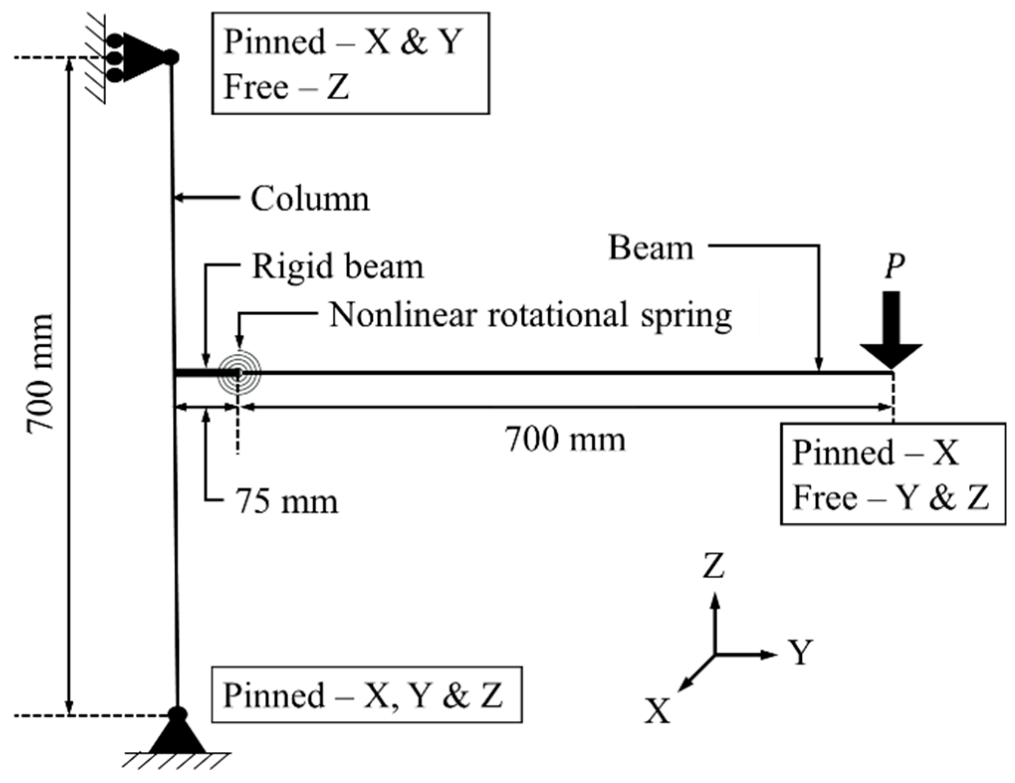
2.2.4. Boundary Conditions and Loading of Module Model

The boundary conditions for the module model were assumed to be that of a module located at the corner of the building, with the adjoining modules providing no rotational restraint but translational restraint to the corner module under investigation. This is often the most onerous location for damage to occur, as the corner module can only redistribute load to the adjoining modules on one side in either axis [16,18]. The load redistribution, therefore, heavily relies on the Vierendeel action of the frame rather than catenary action due to minimum continuity between module frames and no continuity between floor slabs. To investigate the M-θ behaviour of the joints (well into the nonlinear range) in redistributing vertical load via Vierendeel action, a displacement-controlled pull-down load was statically applied to the model at Point G, as indicated in Figure 3. A large displacement analysis was used until numerical converge failure, which indicated the onset of rapid material failure in the model. The 3D frame model was pin-supported at various locations in the direction of red arrows, as indicated in Figure 3. The purpose of using a displacement-controlled pull-down load in addition to the notional removal instead of only notional removal was to ensure that the full nonlinear M-θ behaviour of intra-module connections could be captured and replicated in the SR-BEM.

2.2.5. Numerical Analyses

In the analysis, the two long wall beams of the module SR-BEM were subjected to line loads of four different load cases (LC1—service, LC2—ultimate, LC3—accidental, and LC4—equivalent static accidental loads) to estimate the maximum vertical deflection of the unsupported column under a loss of support scenario. The application of line load along the two long wall beams assumed a simply supported one-way spanning module floor. Module floors are typically made of concrete slabs, steel cassette or composite floor systems. In this paper, the module floor was assumed to be a 150 mm precast concrete slab to assess the worst-case scenario in terms of the robustness of the module, as a floor with a higher dead-to-live load ratio might have adversely affected the robustness of the module [37]. Therefore, the concrete slab was not modelled and did not contribute to the stiffness of the module. This was to ensure that a lower bound robustness was obtained and could be applied to a similar corner-supported module with different floor systems. In Table 1, different combinations of line load applied to the module SR-BEM are summarised. The difference between the service and ultimate load combinations is that the latter is a factored sum of the individual load components, while the former is an unfactored sum. For the accidental load combination, the individual load components were added, with a reduction factor applied to the live load components, assuming the building was not fully occupied at failure. The first three load combinations were calculated as per BS EN 1990 [38]. To account for the inertia effect, in the static analysis, as the building attempts to redistribute the load after suffering from damage, the last load combination in Table 1 was amplified as per GSA [23] and DoD [39] specifications.

3. Results and Discussion

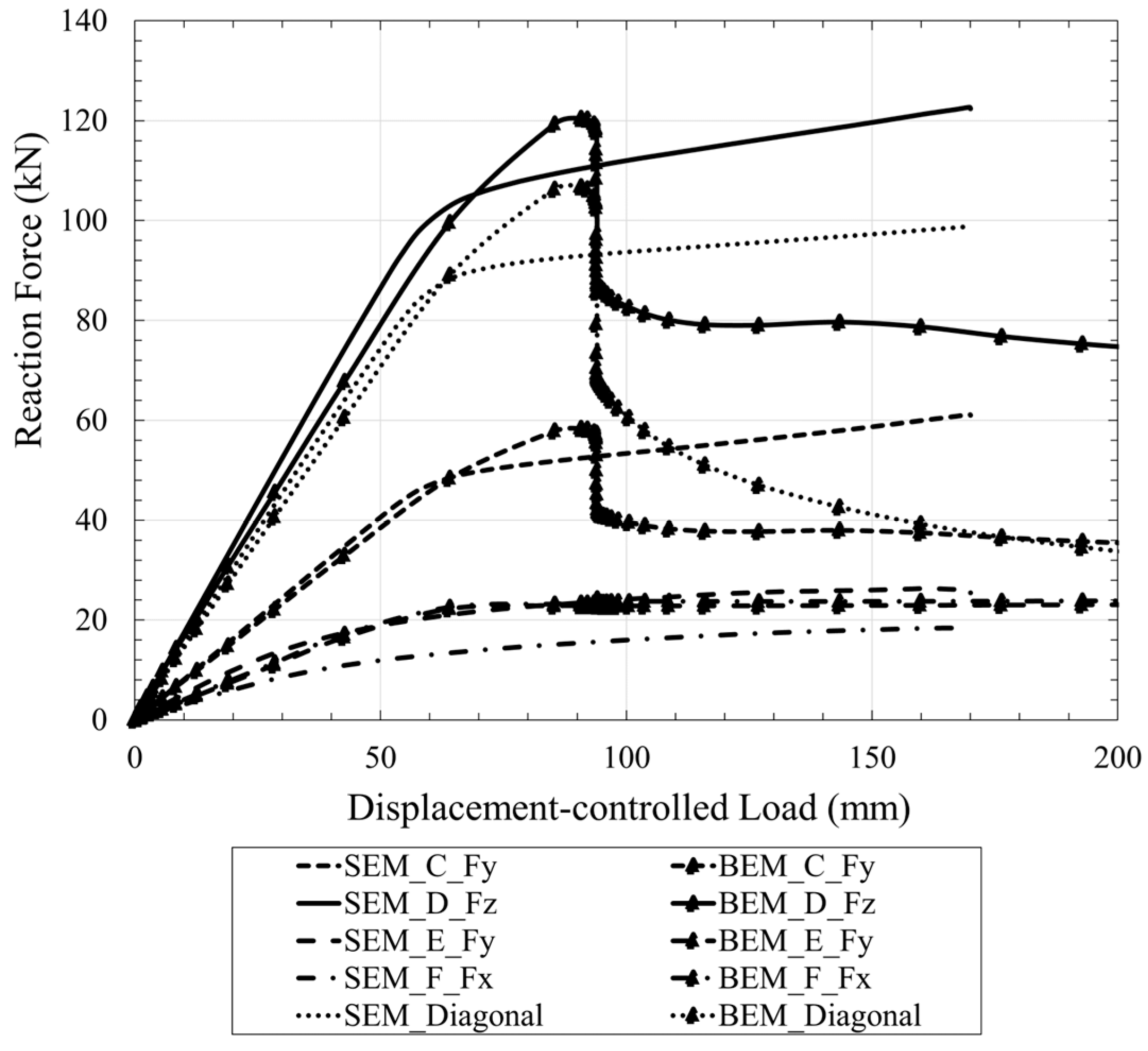
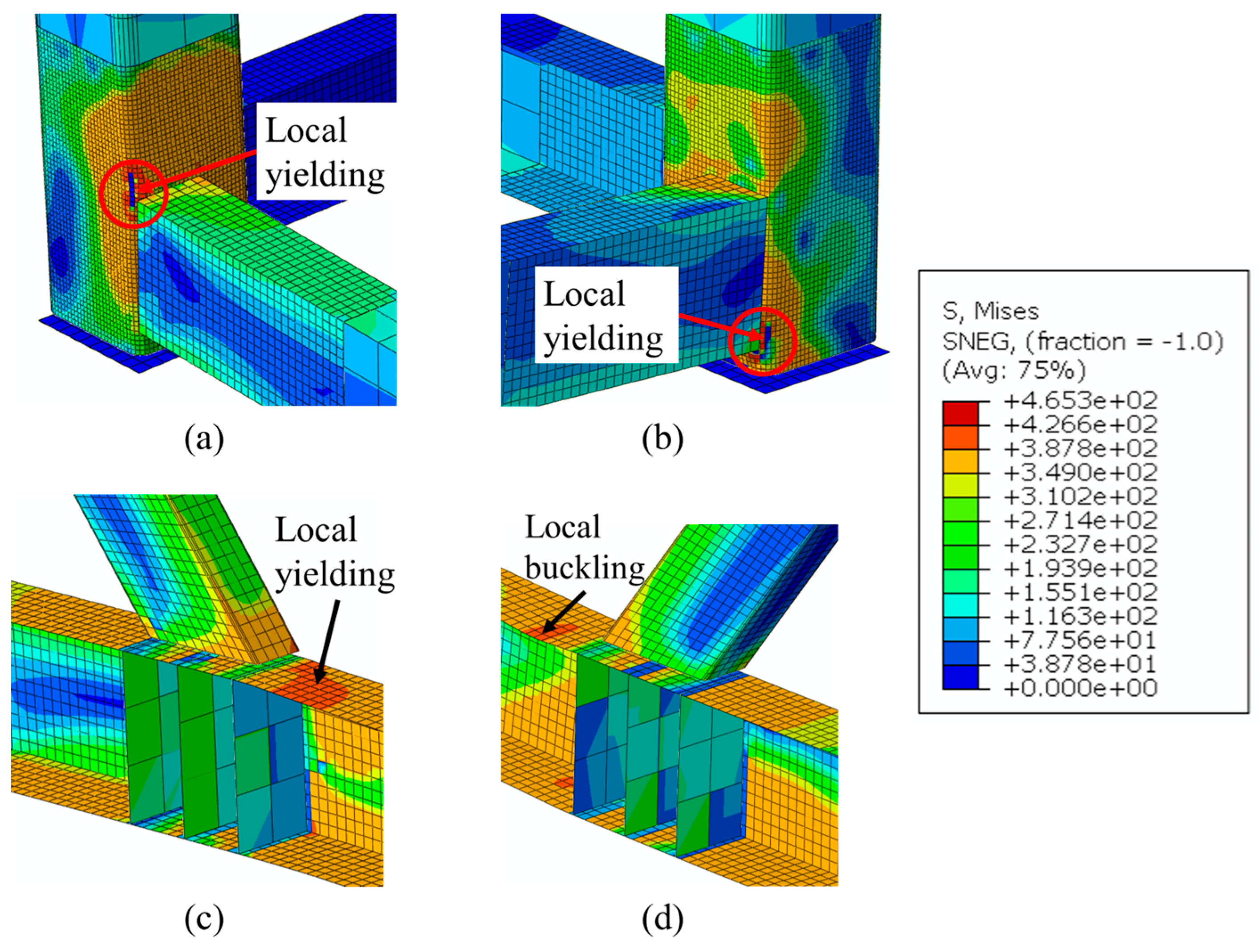
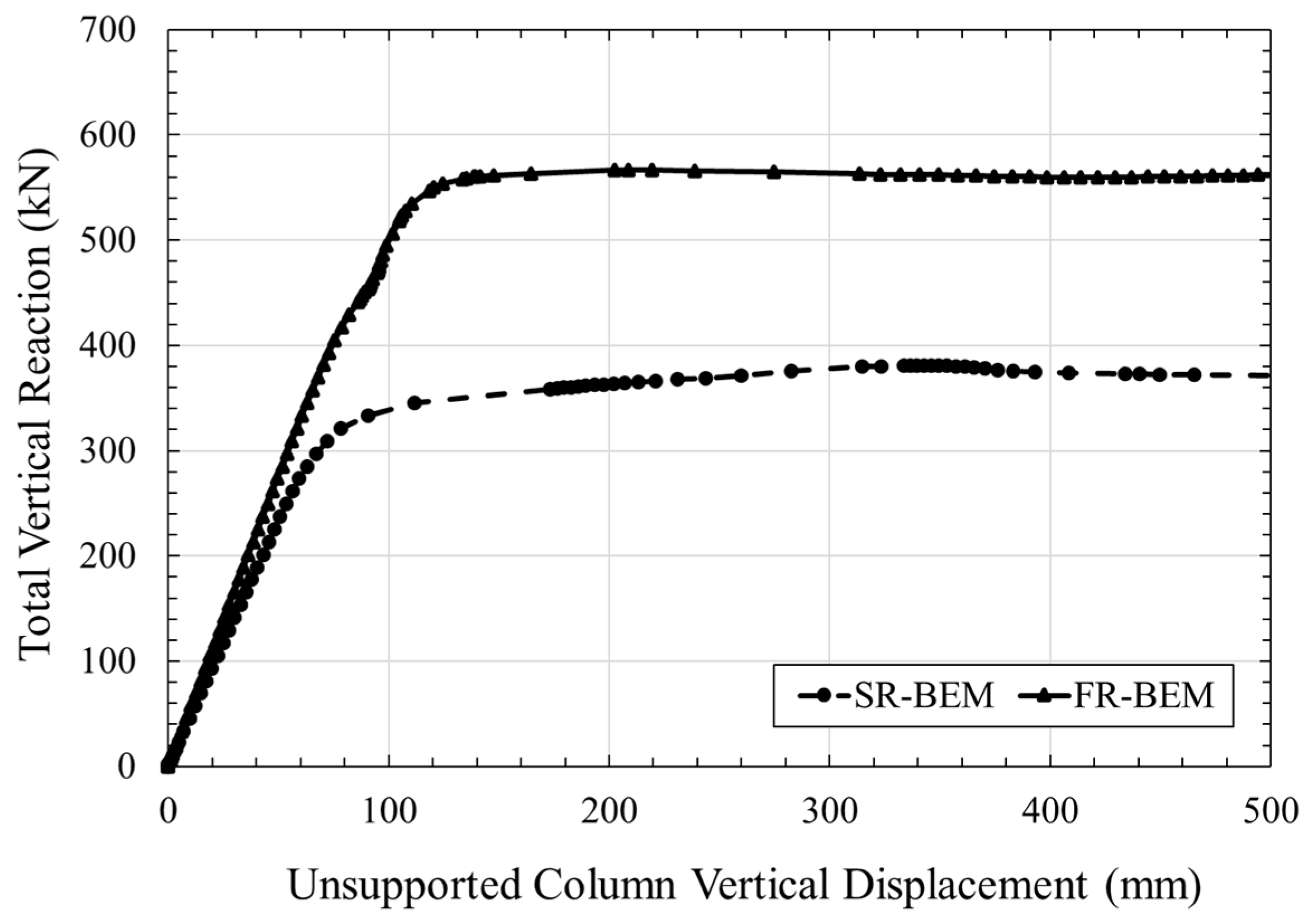
3.1. Structural Response Comparison of Full Module SR-BEM and SEM Subjected to Displacement-Controlled Pull-Down Load

A displacement-controlled pull-down load was applied to the unsupported corner (Point G in Figure 3, i.e., notional support removal). Figure 11 shows the axial compressive force in the diagonal brace and reaction force generated at module Supports C, D, E, and F (indicated in Figure 3) in both the module SR-BEM and SEM. The colour-coded solid lines represent the forces for the SEM, while colour-coded dash lines represent that for the SR-BEM. For instance, the legend ‘SEM_C_Fy’ indicates the reaction force in the y-direction at Support C of SEM (Figure 3).
From Figure 11, the diagonal brace in the SR-BEM buckled at approximately 104 kN, which is 4% under the calculated buckling load of 108 kN for a 3.5 m long brace with an effective length factor of 0.7, assuming fully rigid welded fixed ends. For the SEM, no buckling was observed in the diagonal braces. In fact, the maximum compression load attained by the diagonal brace in the SEM (89.5 kN) was 14% lower than that in the SR-BEM. This observation was mainly due to the presence of local yielding (i.e., locally exceeding material yield strength illustrated in Figure 10) and deformation in the SEM at the column face and beam flange where the diagonal brace was connected (see Figure 12c,d). The local second-order effects at either end of the brace cause a redistribution of the compression load in the brace and prevent the brace from reaching its buckling load in the SEM. Whereas in the SR-BEM, the semi-rigidity of the joints at the ends of diagonal braces was not accounted for, and, hence, the brace buckled. However, within the elastic zone, both the SEM and SR-BEM perform similarly when comparing their support reactions. Beyond the elastic zone, buckling governed the failure of the SR-BEM while yielding, and local buckling (after excessive plastic rotation) governed the ductile failure in the SEM. The other difference observed was the reaction force at Support F in the SEM was lower (by 30%) than that in the SR-BEM. This could be due to the presence of eccentricity in the brace-to-column joint in the SEM as all the braces were positioned flush to the outside edge of the module and, therefore, altered the load distribution ratio between the short and long wall. This was not the case in the SR-BEM, as all the structural members were connected concentrically. Therefore, the long wall in the SEM attracted more loads, as shown in the Support D reaction force. After substantial plastic deformation, the SEM failed to converge at approximately 170 mm displacement load, which signified the onset of rapid material failure in the model.
In Figure 13, the joints yielded in the long and short walls of the SEM directly resisting the displacement-controlled load were indicated in red dots. The sequence in which the joints reached the first yield followed the number indicated on the joints, with number 1 being the first joint to yield under loading. In the case where one of the corner columns was damaged, both walls would be statically indeterminate to the third degree, which would require all four welded joints on each wall to form a plastic hinge for a collapse mechanism to occur. The plastic hinges required for the module frame to form a collapse mechanism were 1, 2, 5, and 6 on the short wall and 3, 4, 10, and 12 on the long wall. Figure 12 shows the close-up view of material failure at the first four most highly stressed joints in Figure 13. The sequence of failure was Joint 1, 2, 3, and 4. After yielding in Joint 4, the analysis failed to converge.
Table 2 compares the model characteristics and computational time required to run the SEM and SR-BEM. All the analyses in this paper were performed using AMD Ryzen 5 5600X 6-Core Processor with 3.7 and 4.6 GHz of base and peak clock speed, respectively. Despite the structural responses between the two models being slightly different towards the peak (see Figure 11) due to local softening at the brace connections in the SEM, the computational effort of using the SR-BEM was significantly lower than the SEM. Comparing the normalised computational time (i.e., computational time per finite element), the SR-BEM took 95.8% less time while requiring 97.4% less RAM than the SEM. This paper analysed a single module, and, hence, the computational time when scaled up to a full building would be significant.

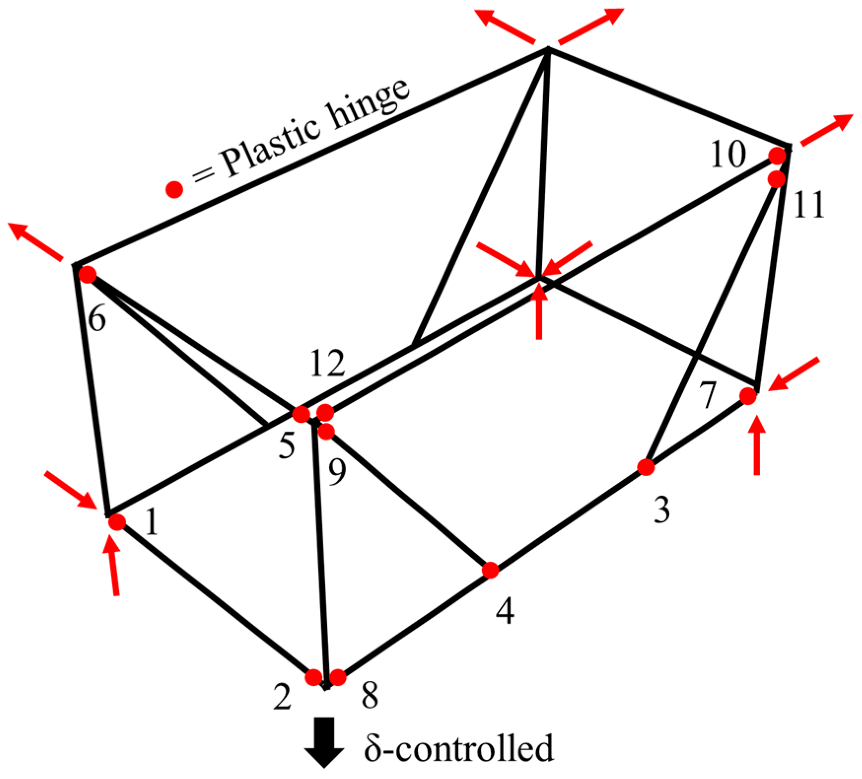
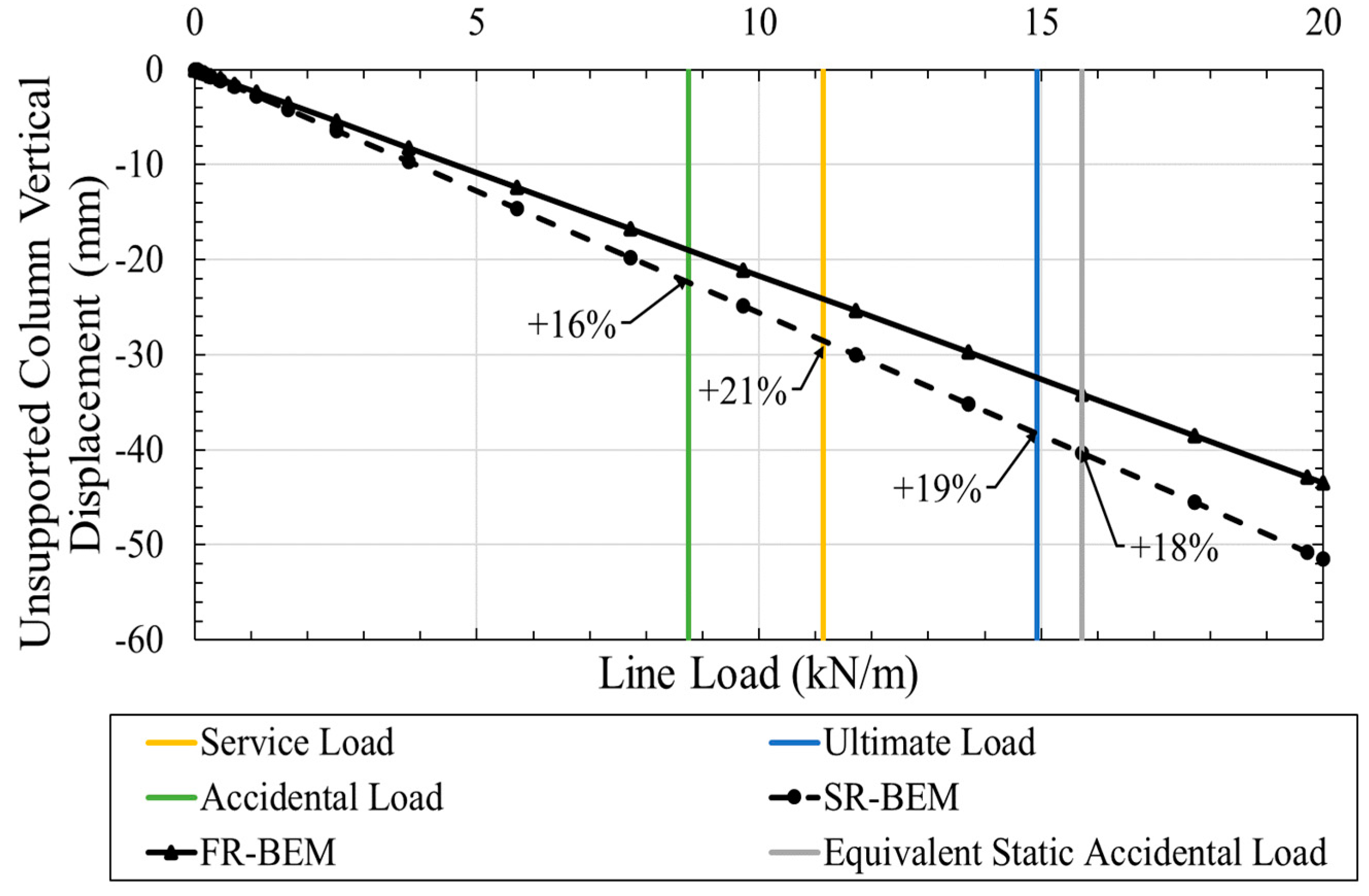
3.2. Robustness Assessment of FR-BEM and SR-BEM

The structural response of the FR- and SR-BEM framed corner-supported module under normal and accidental loading scenarios (refer to Table 1) was investigated next. A line load with magnitudes given in Table 1 was applied to the two long wall beams in both BEMs, assuming a one-way spanning simply supported floor system. The vertical displacements of the unsupported corner column for both models were shown in Figure 14, with the percentage of additional vertical displacement of the unsupported column in the SR-BEM relative to the FR-BEM, indicated at different loading combinations. As expected, at least 16% additional displacement was observed at the unsupported column in the SR-BEM for all load combinations. However, it should be noted that the linear relationship between the column displacement and the line load magnitude indicates all welded joints in the SR-BEM remain in their elastic range up to 20 kN/m of line load. This indicates that the structure performs well under notional element support removal when subjected to different load combinations.
In relation to the support reactions following the removal of Support G, they were summarised in Table 3 for both FR-BEM and SR-BEM. The percentage difference in support reaction following the removal of Support G of the SR-BEM relative to the FR-BEM is summarised in Table 4. For example, ‘A (Fy)’ in the tables indicates the support reaction in the y-direction of Support A. From Table 3 and Table 4, it can be seen that the vertical support reaction at the internal corner of the module (i.e., Support A in Figure 3) remain virtually unchanged across all load cases. Although a greater change (average 17.8–24.3%) was observed at the top support of the internal corner (Support B), the magnitudes of those reactions were insignificant. This observation is as expected because most redistribution of load was directly resisted by two orthogonal frames (EFGH and CDGH in Figure 3) with the shortest load path to supports at the corner of the module. Comparing the remaining support of the reaction at Support C, D, E, and F, lower redistribution of the load (i.e., at least −7% on average) occurred along the short wall frame (EFGH) in the SR-BEM compared to the FR-BEM. This is because a stiffer connection is beneficial for the short wall frame utilising the Vierendeel mechanism and hence attracts more loads in the fully rigid model. Consequently, to achieve equilibrium, more loads have to be resisted by the long wall frame (CDGH), which requires the unsupported column loads to travel further vertically to effectively engage the Vierendeel truss resisting mechanism in the long wall frame. It is worth noting that the percentage differences remain virtually unchanged for different magnitudes of line load investigated, which indicates that both the SR- and FR-BEMs’ responses remain elastic for all investigated loads.
To investigate the load-displacement response of the SR- and FR-BEMs further (i.e., beyond yield), a large magnitude of line load (i.e., 100 kN/m) was applied to the two long walls, and their respective response was summarised in Figure 15. Although 100 kN/m of line load was applied to the two long walls of each model, only 32% (380.9 kN) and 54% (646.4 kN) of the applied load were resisted by the SR-BEM and FR-BEM, respectively. Beyond that, the connections in the frames yield rotate plastically, leading to the increase in vertical displacement of the unsupported column with no increase in the vertical load being resisted by the frame (i.e., vertical support reactions). To summarise, it can be seen that local flexibility in the SR-BEM due to welded hollow section joints could affect the vertical stiffness and robustness of corner-supported MSBs after the removal of support, especially in a highly nonlinear progressive collapse scenario. The lower prediction of the unsupported displacement in the rigid model could underestimate the second-order effects following the damage of column(s) and, ultimately, overestimate the robustness of a corner-supported MSB.

4. Conclusions

In this paper, a new phenomenological SR-BEM of a corner-supported module made of hollow section columns with semi-rigid connection rotational stiffness is presented. Overall, the SR-BEM with nonlinear rotational springs performs closely when compared to experimental results of header-to-column connections and to validated SEM. A robustness comparison between the typically assumed fully rigid and actual semi-rigid connection rotational stiffnesses is performed. Although only a single module was investigated in this study, it demonstrates that the vertical stiffness of a typical corner-supported module has a significant impact on the robustness of a single module, not to mention a full building, where the effect accumulates through the full height of the building. The findings of this paper are summarised as follows:
  • A new phenomenological beam element model (BEM) with bilinear/trilinear M-θ relationship for welded hollow section connections (intra-module) that captures the semi-rigidity of the connections with very good accuracy was developed;
  • The developed SR-BEM requires 98.7% less computational time and 97.4% less computational effort (RAM) than a typical SEM for a similar level of structural accuracy;
  • The SR-BEM performs structurally well under notional support removal when subjected to different load combinations (service, ultimate, accidental, and equivalent static accidental loads);
  • For the corner column removal scenario, redistribution of loads to the internal corner supports is negligible;
  • On average, a 16% increase in the horizontal support reaction (i.e., tie force) was observed in the long wall support, with a 22.3% reduction in the horizontal support reaction in the short wall support in the SR-BEM compared to the FR-BEM;
  • The SR-BEM redistributed 6–7% of the vertical load from the short wall support to the long wall support when compared to the FR-BEM due to the reduced efficiency of the highly stiffness-dependent short-wall Vierendeel frame;
  • An increase of at least 16% vertical displacement was identified in the SR-BEM when compared to FR-BEM under multiple residential-type line loadings;
  • The results demonstrate the importance of modelling the accurate intra-module connections’ rotational stiffness in order to accurately assess the performance of MSBs under notional support removal.

Author Contributions

Conceptualization, S.H.H., D.M., D.H. and M.H.; methodology, S.H.H., D.M. and D.H.; software, S.H.H.; validation, S.H.H.; formal analysis, S.H.H.; investigation, S.H.H. and D.M.; resources, D.M., D.H. and M.H.; data curation, S.H.H.; writing—original draft preparation, S.H.H.; writing—review and editing, S.H.H., D.M., D.H. and M.H.; visualization, S.H.H.; supervision, D.M., D.H. and M.H.; project administration, D.M. and D.H.; funding acquisition, D.M. and M.H. All authors have read and agreed to the published version of this manuscript.

Funding

This research was funded by the Irish Research Council under the Employment-based PhD programme (IRC-EBP), grant number EBPPG/2021/24.

Data Availability Statement

The data presented in this study are available on request from the corresponding author. The data are not publicly available due to commercial reasons.

Acknowledgments

The first author gratefully acknowledges the technical support provided by colleagues in MJH Structural Engineers.

Conflicts of Interest

The authors (Si Hwa Heng and David Hyland) are the employees of MJH Structural Engineers. Michael Hough is the owner of the company, MJH Structural Engineers. The remaining authors declare that the research was conducted in the absence of any commercial or financial relationships that could be constructed as a potential conflict of interest.

References

  1. UN-Habitat. Housing. 2021. Available online: https://unhabitat.org/topic/housing (accessed on 16 November 2022).
  2. Gao, S.; Low, S.P.; Nair, K. Design for manufacturing and assembly (DfMA): A preliminary study of factors influencing its adoption in Singapore. Archit. Eng. Des. Manag. 2018, 14, 440–456. [Google Scholar] [CrossRef]
  3. European-Commission. A European Green Deal. 2023. Available online: https://commission.europa.eu/strategy-and-policy/priorities-2019-2024/european-green-deal_en (accessed on 5 July 2023).
  4. RIBA. Design for Manufacture and Assembly (DfMA) Overlay to the RIBA Plan of Work 2020, 2nd ed.; RIBA: London, UK, 2021. [Google Scholar]
  5. Lu, W.; Tan, T.; Xu, J.; Wang, J.; Chen, K.; Gao, S.; Xue, F. Design for manufacture and assembly (DfMA) in construction: The old and the new. Archit. Eng. Des. Manag. 2021, 17, 77–91. [Google Scholar] [CrossRef]
  6. Lawson, M.; Ogden, R.; Goodier, C. Design in Modular Construction; CRC Press: Boca Raton, FL, USA, 2014. [Google Scholar]
  7. Lowe, T. Modular Construction Emits 45% Less Carbon than Traditional Methods, Report Finds. 2022. Available online: https://www.building.co.uk/news/modular-construction-emits-45-less-carbon-than-traditional-methods-report-finds/5117779.article (accessed on 20 March 2024).
  8. MJH-Structural-Engineers, Ten Degrees, Croydon, UK [Photograph], (2020).
  9. MJH-Structural-Engineers, College Road, Croydon, UK [Photograph], (2023).
  10. Ferdous, W.; Bai, Y.; Ngo, T.D.; Manalo, A.; Mendis, P. New advancements, challenges and opportunities of multi-storey modular buildings—A state-of-the-art review. Eng. Struct. 2019, 183, 883–893. [Google Scholar] [CrossRef]
  11. Thai, H.-T.; Ngo, T.; Uy, B. A review on modular construction for high-rise buildings. Structures 2020, 28, 1265–1290. [Google Scholar] [CrossRef]
  12. Selsey, R.V.; Mofid, K.; Eve, P.; Duggleby, S. Modern Methods of Construction; Savills Research: London, UK, 2020. [Google Scholar]
  13. Liew, J.Y.R.; Chua, Y.S.; Dai, Z. Steel concrete composite systems for modular construction of high-rise buildings. Structures 2019, 21, 135–149. [Google Scholar] [CrossRef]
  14. Lacey, A.W.; Chen, W.; Hao, H.; Bi, K. Structural response of modular buildings—An overview. J. Build. Eng. 2018, 16, 45–56. [Google Scholar] [CrossRef]
  15. Alembagheri, M.; Sharafi, P.; Hajirezaei, R.; Samali, B. Collapse capacity of modular steel buildings subject to module loss scenarios: The role of inter-module connections. Eng. Struct. 2020, 210, 110373. [Google Scholar] [CrossRef]
  16. Chua, Y.S.; Liew, J.Y.R.; Pang, S.D. Robustness of Prefabricated Prefinished Volumetric Construction (PPVC) High-rise Building. In Proceedings of the 12th International Conference on Advances in Steel-Concrete Composite Structures (ASCCS 2018), València, Spain, 27–29 June 2018. [Google Scholar] [CrossRef]
  17. Lawson, R.M.; Richards, J. Modular design for high-rise buildings. Proc. Inst. Civ. Eng.-Struct. Build. 2010, 163, 151–164. [Google Scholar] [CrossRef]
  18. Luo, F.J.; Bai, Y.; Hou, J.; Huang, Y. Progressive collapse analysis and structural robustness of steel-framed modular buildings. Eng. Fail. Anal. 2019, 104, 643–656. [Google Scholar] [CrossRef]
  19. Swami, G.; Thai, H.-T.; Liu, X. Structural robustness of composite modular buildings: The roles of CFST columns and inter-module connections. Structures 2023, 48, 1491–1504. [Google Scholar] [CrossRef]
  20. Shan, S.; Pan, W. Progressive collapse mechanisms of multi-story steel-framed modular structures under module removal scenarios. Structures 2022, 46, 1119–1133. [Google Scholar] [CrossRef]
  21. Peng, J.; Hou, C.; Shen, L. Progressive collapse analysis of corner-supported composite modular buildings. J. Build. Eng. 2022, 48, 103977. [Google Scholar] [CrossRef]
  22. BS 5950-1:2000; Structural Use of Steelwork in Building—Part 1: Code of Practice for Design–Rolled and Welded Sections. British Standards Institution: London, UK, 2000.
  23. GSA. General Services Administration Alternate Path Analysis and Design Guidelines for Progressive Collapse Resistance; General Services Administration: Washington, DC, USA, 2016. [Google Scholar]
  24. BS EN 1993-1-1:2005; Eurocode 3: Design of Steel Structures—Part 1-1: General Rules and Rules for Buildings. British Standards Institution: London, UK, 2005.
  25. Thai, H.-T.; Ho, Q.V.; Li, W.; Ngo, T. Progressive collapse and robustness of modular high-rise buildings. Struct. Infrastruct. E 2021, 19, 302–314. [Google Scholar] [CrossRef]
  26. Chua, Y.S.; Pang, S.D.; Liew, J.Y.R.; Dai, Z. Robustness of inter-module connections and steel modular buildings under column loss scenarios. J. Build. Eng. 2022, 47, 103888. [Google Scholar] [CrossRef]
  27. Grotmann, D.; Sedlacek, G. Rotational Stiffness of Welded RHS Beam-to-Column Joints; Final Report No. 5BB–8/98, RWTH-Aachen; Institute of Steel Construction: Aachen, Germany, 1998. [Google Scholar]
  28. Havula, J.; Garifullin, M.; Heinisuo, M.; Mela, K.; Pajunen, S. Moment-rotation behavior of welded tubular high strength steel T joint. Eng. Struct. 2018, 172, 523–537. [Google Scholar] [CrossRef]
  29. Garifullin, M.; Pajunen, S.; Mela, K.; Heinisuo, M.; Havula, J. Initial in-plane rotational stiffness of welded RHS T joints with axial force in main member. J. Constr. Steel Res. 2017, 139, 353–362. [Google Scholar] [CrossRef]
  30. SIMULIA, Abaqus 2021 Documentation. 2021. Available online: https://help.3ds.com/2021/English/DSSIMULIA_Established/SIMULIA_Established_FrontmatterMap/sim-t-SIMULIA_EstablishedDocSearchOnline.htm?contextscope=all (accessed on 20 March 2024).
  31. Heng, S.H.; McCrum, D.; Hyland, D.; Hough, M. Robustness of Square Hollow Column Sections in Open-sided Corner-supported Modular Steel Buildings. In Civil Engineering Research in Ireland 2022 and Irish Transport Research Network 2022; Holmes, N., Paor, C.D., West, R.P., Eds.; Civil Engineering Research Association of Ireland: Dublin, Ireland; Technological University of Dublin: Dublin, Ireland; Trinity College Dublin: Dublin, Ireland, 2022; pp. 195–200. [Google Scholar]
  32. Chua, Y.S.; Liew, J.Y.R.; Pang, S.D. Modelling of connections and lateral behavior of high-rise modular steel buildings. J. Constr. Steel Res. 2020, 166, 105901. [Google Scholar] [CrossRef]
  33. Lawson, M. SCI P348: Building Design Using Modules; The Steel Construction Institute: Ascot, Australia, 2007. [Google Scholar]
  34. BS EN 1993-1-5:2006; Eurocode 3: Design of Steel Structures—Part 1–5: Plated Structural Elements. British Standards Institution: London, UK, 2006.
  35. BS EN 10025-2:2019; Hot Rolled Products of Structural Steels—Part 2: Technical Delivery Conditions for Non-Alloy Structural Steels. British Standards Institution: London, UK, 2019.
  36. Uriz, P.; Filippou, F.C.; Mahin, S.A. Model for Cyclic Inelastic Buckling of Steel Braces. J. Struct. Eng. 2008, 134, 619–628. [Google Scholar] [CrossRef]
  37. Lawson, P.M.; Byfield, M.P.; Popo-Ola, S.O.; Grubb, P.J. Robustness of light steel frames and modular construction. Proc. Inst. Civ. Eng.—Struct. Build. 2008, 161, 3–16. [Google Scholar] [CrossRef]
  38. BS EN 1990:2002+A1:2005; Eurocode—Basis of Structural Design. British Standards Institution: London, UK, 2005.
  39. UFC 4-023-03; Design of Buildings to Resist Progressive Collapse. United States Department of Defense: Washington, DC, USA, 2016.
Figure 1. (a) Ten Degrees, Croydon, UK (reproduced with permission from [8]); (b) College Road, Croydon, UK (reproduced with permission from [9]).
Modelling 05 00021 g001
Figure 2. Isometric view of a typical (a) corner-supported and (b) wall-bearing modules.
Modelling 05 00021 g002
Figure 3. Isometric view of 3D frame model.
Modelling 05 00021 g003
Figure 4. The connection between the SHS header and SHS column using SEM with 5 mm square mesh refinement.
Modelling 05 00021 g004
Figure 5. M-θ relationship of welded joint with different mesh density.
Modelling 05 00021 g005
Figure 6. Von Mises stress and failure mode for different mesh densities at approximately 0.2 rad rotation θ.
Modelling 05 00021 g006
Figure 7. M-θ relationship of 5 mm square mesh SEM model vs. test results [28].
Modelling 05 00021 g007
Figure 8. The connection between the header and column in the SR-BEM (reproduced with permission from [31]).
Modelling 05 00021 g008
Figure 9. M-θ relationship of SR-BEM and SEM vs. test results (reproduced with permission from [31]).
Modelling 05 00021 g009
Figure 10. Simplified S355 material stress vs. strain curve (data obtained from [35]).
Modelling 05 00021 g010
Figure 11. Reaction force generated at the supports of the SEM and SR-BEMs due to displacement-controlled pull-down load.
Modelling 05 00021 g011
Figure 12. SEM with close-up view of joint yielding due to displacement-controlled pull-down load at (a) Joint 1, (b) Joint 2, (c) Joint 3, and (d) Joint 4 from Figure 13.
Modelling 05 00021 g012
Figure 13. Schematic isometric view of module frame joints reaching first yield (labelled in sequence) under displacement-controlled pull-down load.
Modelling 05 00021 g013
Figure 14. Displacement response of FR-BEM and SR-BEM under various load cases.
Modelling 05 00021 g014
Figure 15. Full load-displacement response of SR- and FR-BEM subjected to large line loads.
Modelling 05 00021 g015
Table 1. Combined loading for different load combinations.
Load CaseLoad TypesFloor aFinishesLive Load bImposed Load cTotal Load
Area (kN/m2)Line d (kN/m)
Magnitude (kN/m2)3.750.51.51.0
LC1Service load e (kN/m2) γ G , 1 , s u p G k , 1 γ G , 2 , s u p G k , 2 γ Q , 1 Q k , 1 γ Q , 2 Q k , 2 6.7511.14
1.0 × 3.751.0 × 0.51.0 × 1.51.0 × 1.0
LC2Ultimate load e (kN/m2) γ G , 1 , s u p G k , 1 γ G , 2 , s u p G k , 2 γ Q , 1 Q k , 1 γ Q , 2 ψ 0,2 Q k , 2 9.0414.92
1.35 × 3.751.35 × 0.51.5 × 1.51.5 × 0.7 × 1.0
LC3Accidental load e (kN/m2) γ G , 1 , s u p G k , 1 γ G , 2 , s u p G k , 2 γ Q , 1 ψ 1,1 Q k , 1 γ Q , 2 ψ 2,2 Q k , 2 5.308.75
1.0 × 3.751.0 × 0.51.0 × 0.5 × 1.51.0 × 0.3 × 1.0
LC4Equivalent static accidental load with dynamic f (kN/m2) Ω N ( 1.2 D 1 ) Ω N ( 1.2 D 2 ) Ω N ( 0.5 L 1 ) Ω N ( 0.5 L 2 ) 9.5315.72
1.5 × 1.2 × 3.751.5 × 1.2 × 0.51.5 × 0.5 × 1.51.5 × 0.5 × 1.0
a 150 mm thick solid concrete floor with 25 kN/m3 density. b Typical residential live load (leading variable). c Typical partition load (accompanying variable). d Line load is calculated by multiplying the area load by half the module width (wall load not included). e Partial factors for service, ultimate and accidental load combinations as per BS EN 1990 [38]. f Worst case dynamic amplification factor (for welded joints) and load factor as per GSA [23] and DoD [39] specifications.
Table 2. Single module SEM and SR-BEM efficiency and effort comparison.
ModelSEMBEM% Difference
Finite ElementS4RB32/B32OS-
No. of integration points per element12N/A
Total no. of finite elements176,972100-
Computational runtime (s)578478−98.7%
Minimum RAM required (MB)66117−97.4%
Normalised computational time 30.61.3−95.8%
Table 3. Supports reaction of SR-BEM vs. FR-BEM for all load cases.
Load TypesLine Load (kN/m)ModelSupport Reactions (kN)
A (Fy)B (Fx)B (Fz)C (Fy)D (Fz)E (Fy)F (Fx)
Service11.14FR-BEM33.70.0710.48053.040.247.014.5
SR-BEM33.70.0590.36656.146.643.911.2
Ultimate14.92FR-BEM45.10.0880.62470.953.863.019.4
SR-BEM45.10.0710.46975.162.458.915.0
Accidental8.75FR-BEM26.50.0590.38541.631.636.911.3
SR-BEM26.40.0500.29644.136.634.58.79
Equivalent Static Accidental15.72FR-BEM47.50.0910.65374.756.766.320.4
SR-BEM47.50.0730.49079.165.762.015.8
Table 4. Percentage difference in supports reaction of SR-BEM relative to FR-BEM for all load cases.
Load TypesLine Load (kN/m)Percentage Difference in Supports Reaction
A (Fy)B (Fx)B (Fz)C (Fy)D (Fz)E (Fy)F (Fx)
Service11.140%−16%−24%6%16%−7%−22%
Ultimate14.920%−20%−25%6%16%−7%−22%
Accidental8.750%−15%−23%6%16%−7%−23%
Equivalent Static Accidental15.720%−20%−25%6%16%−7%−22%
Average-0%−17.8%−24.3%6%16%−7%−22.3%
Disclaimer/Publisher’s Note: The statements, opinions and data contained in all publications are solely those of the individual author(s) and contributor(s) and not of MDPI and/or the editor(s). MDPI and/or the editor(s) disclaim responsibility for any injury to people or property resulting from any ideas, methods, instructions or products referred to in the content.

