
Contact Analysis of Mobility Devices Based on Tension


Abstract
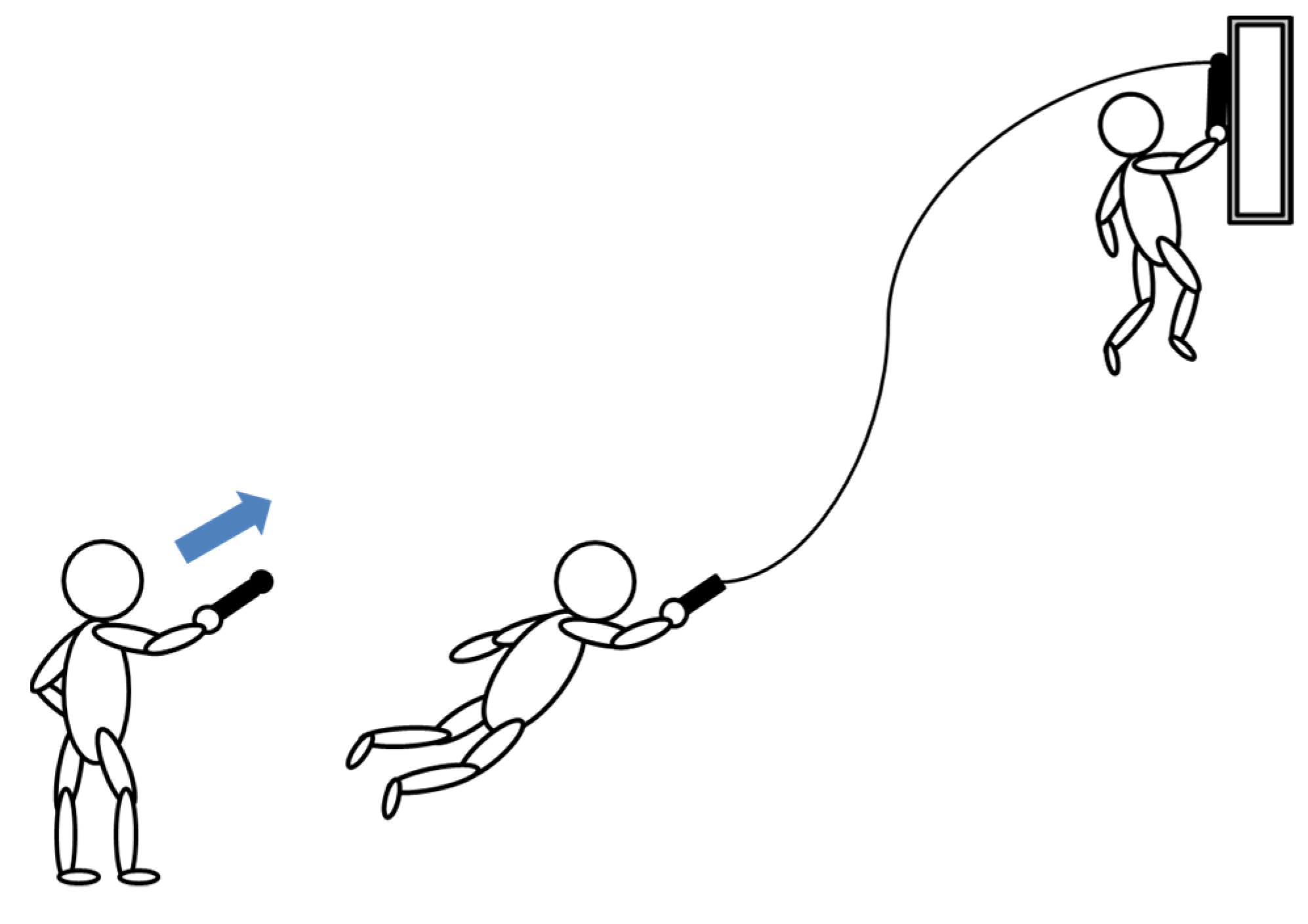
:1. Introduction
2. Analysis Model
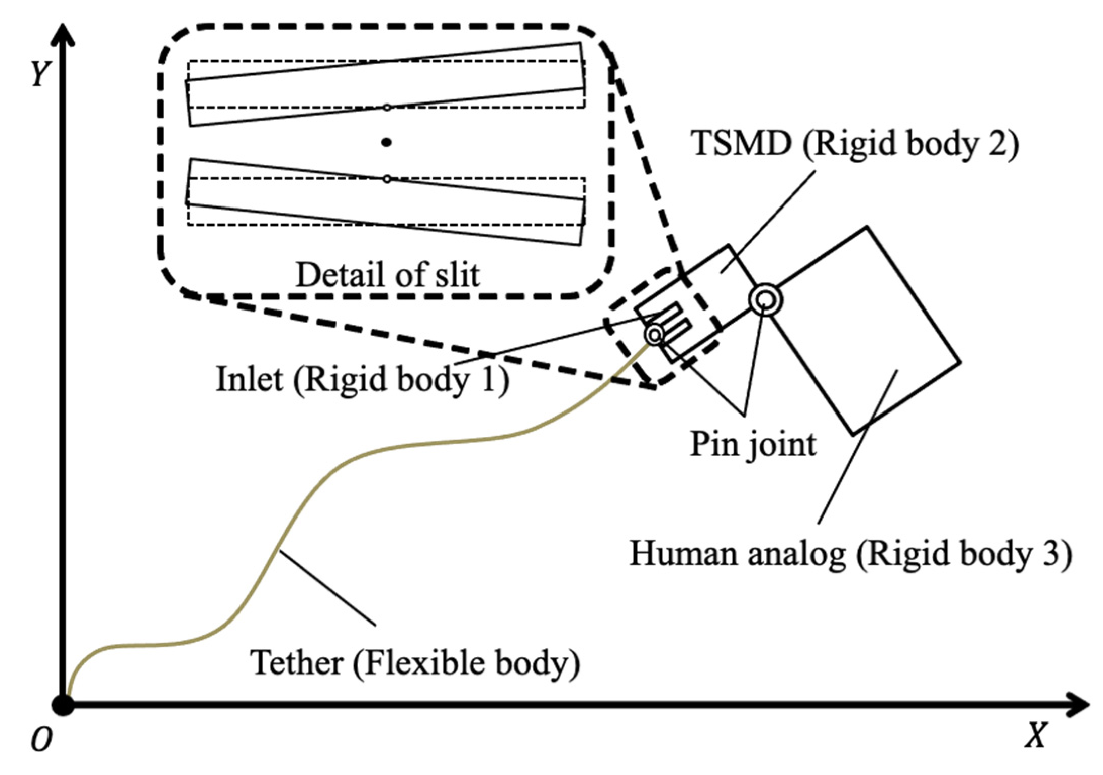
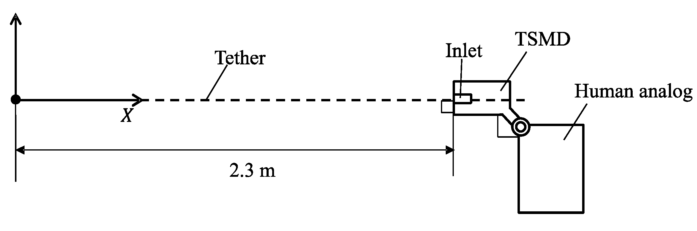
2.1. Formulation of Analytical Model
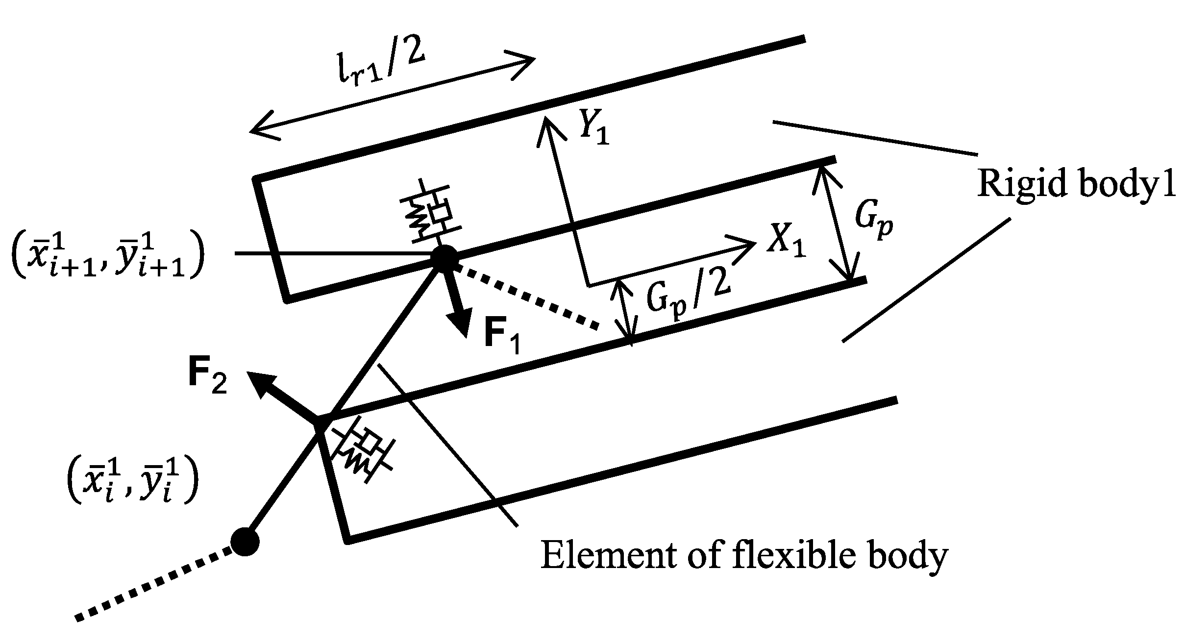
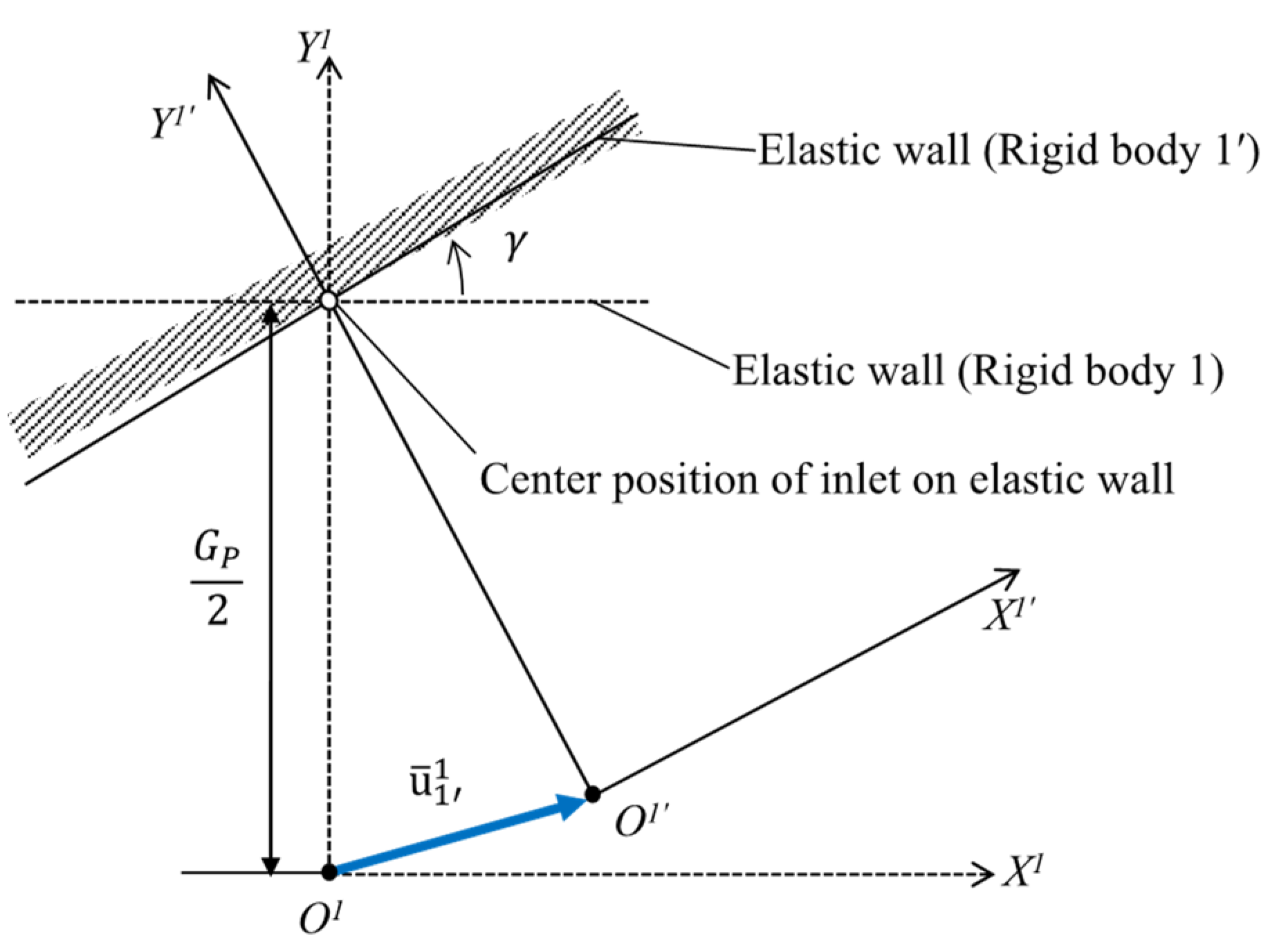
2.2. Contact Force between Flexible and Rigid Bodies
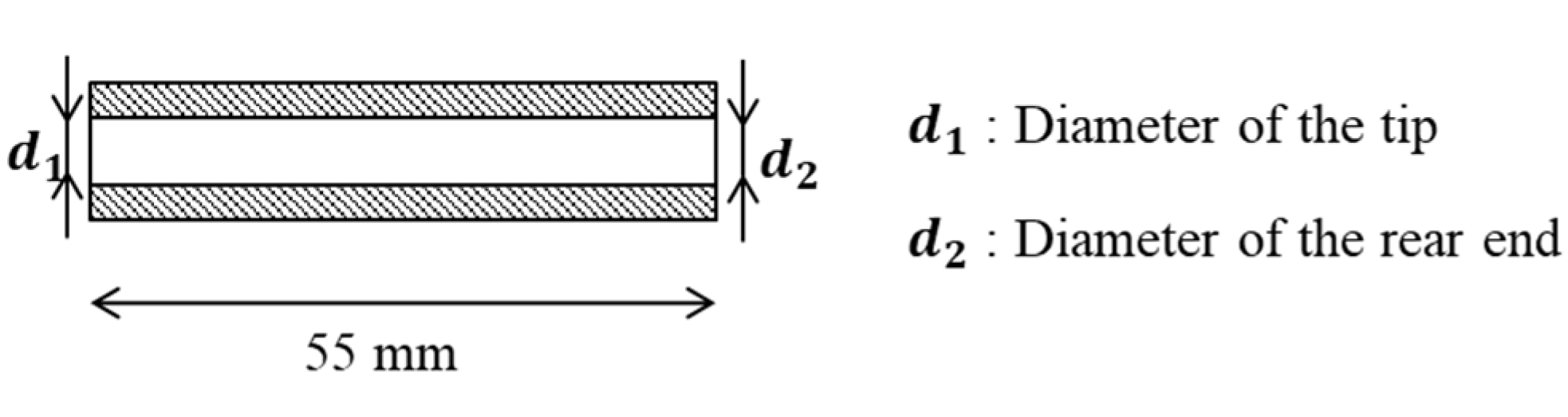
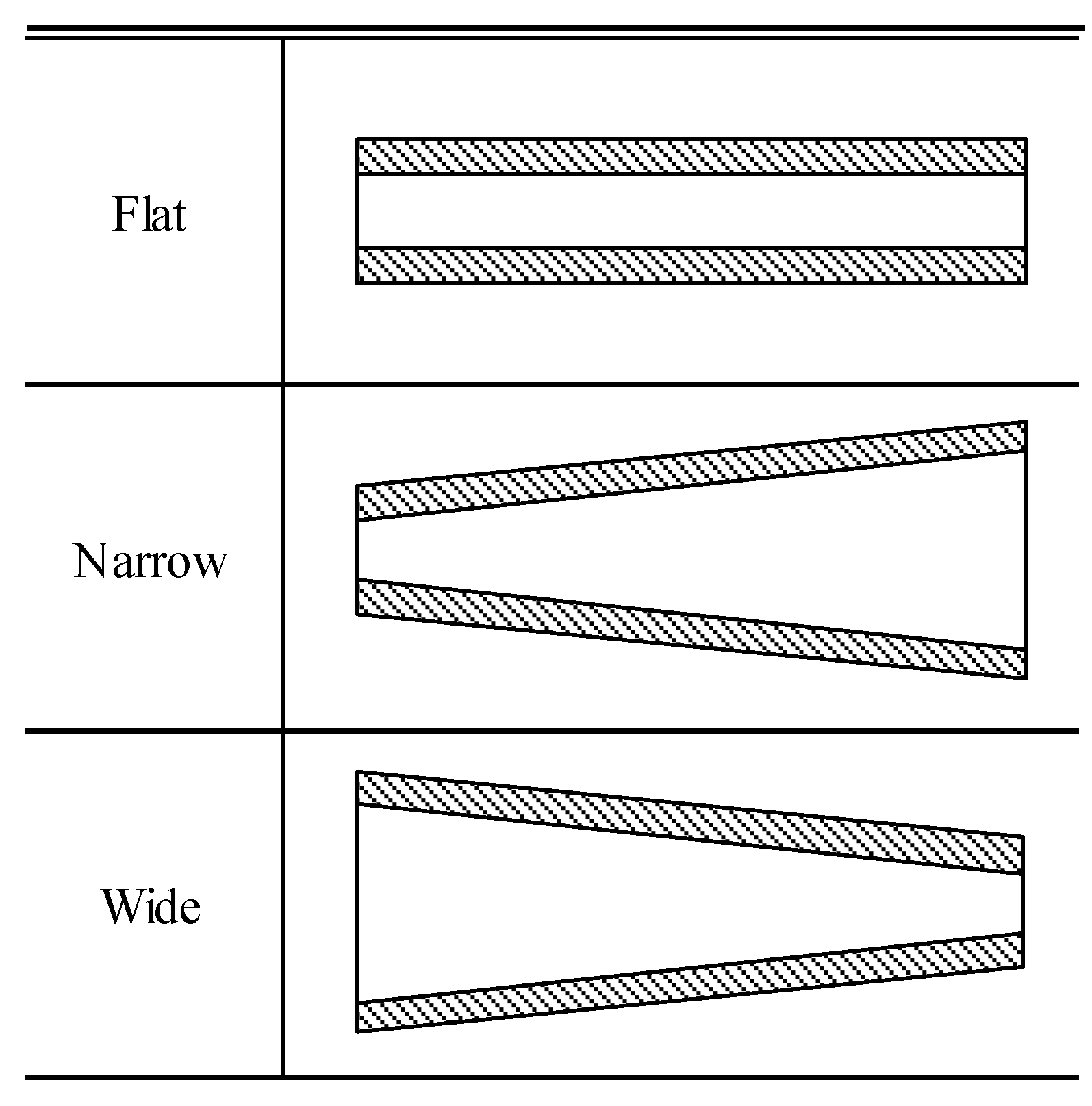
2.3. Adjustment of Slit Shape
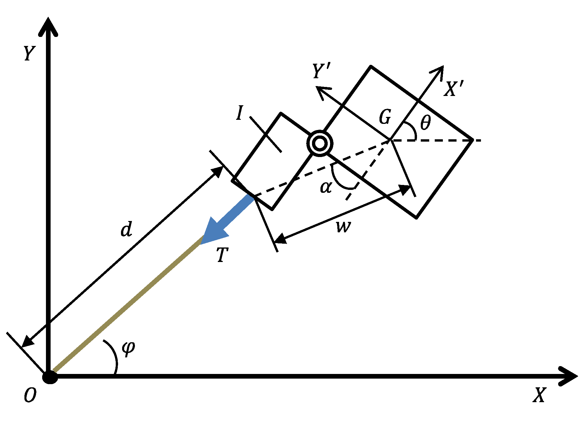
2.4. Posture Control Method
3. Evaluation of Posture Control Method for Each Shape
3.1. Analysis Conditions
3.1.1. Elastic Wall Slit Shape
3.1.2. Initial Conditions
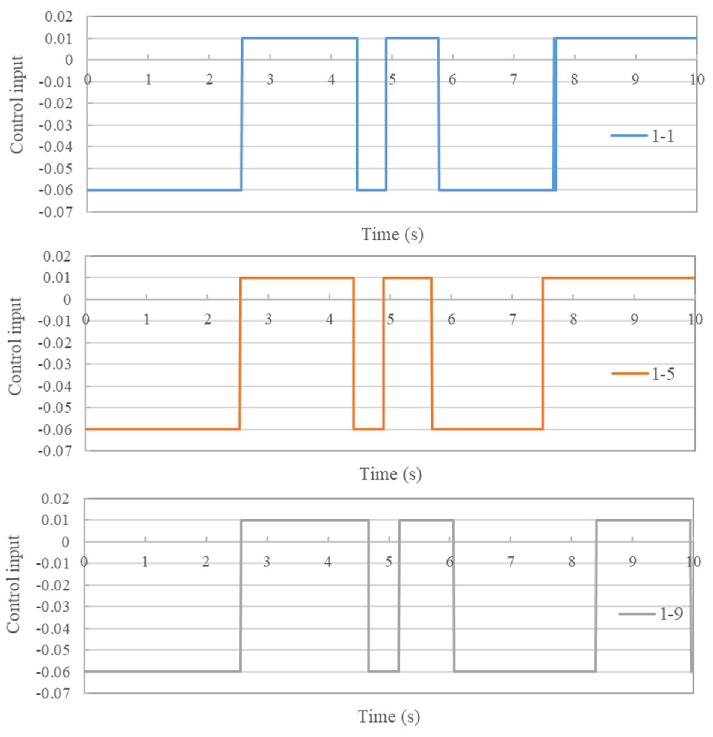
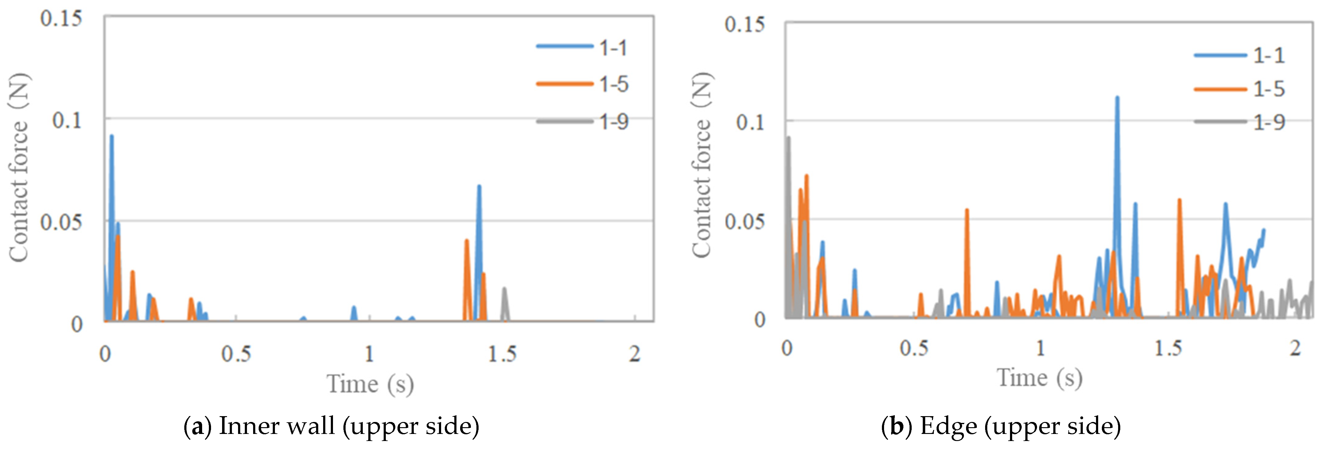
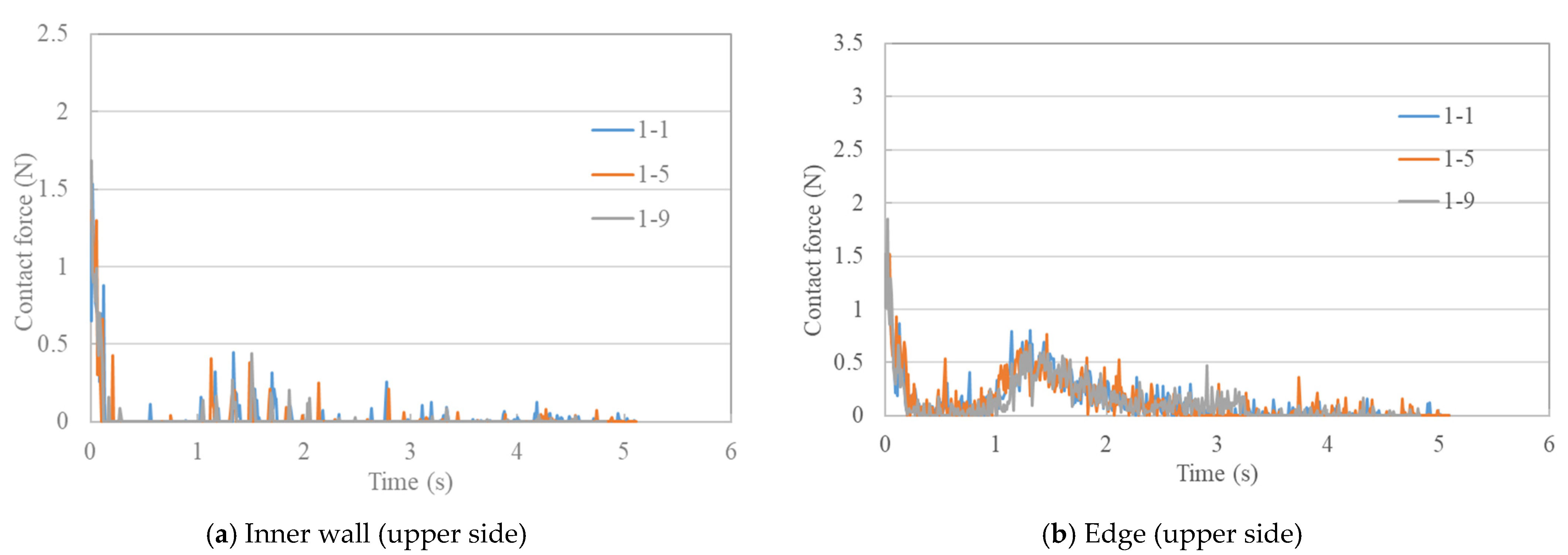
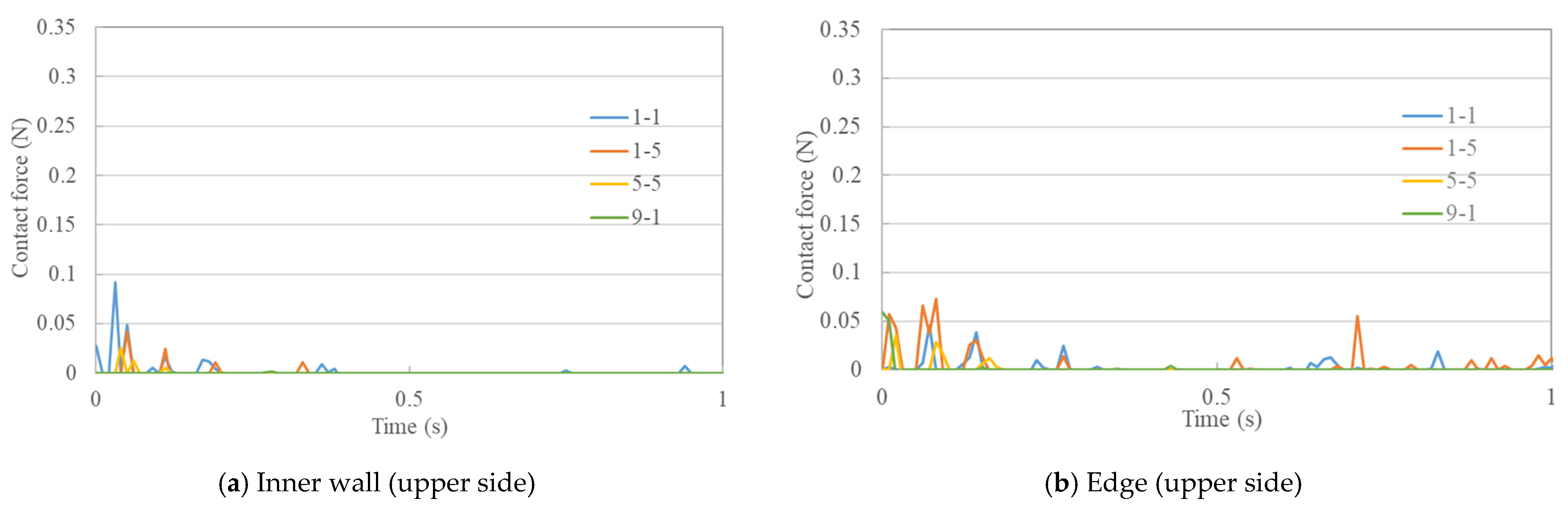
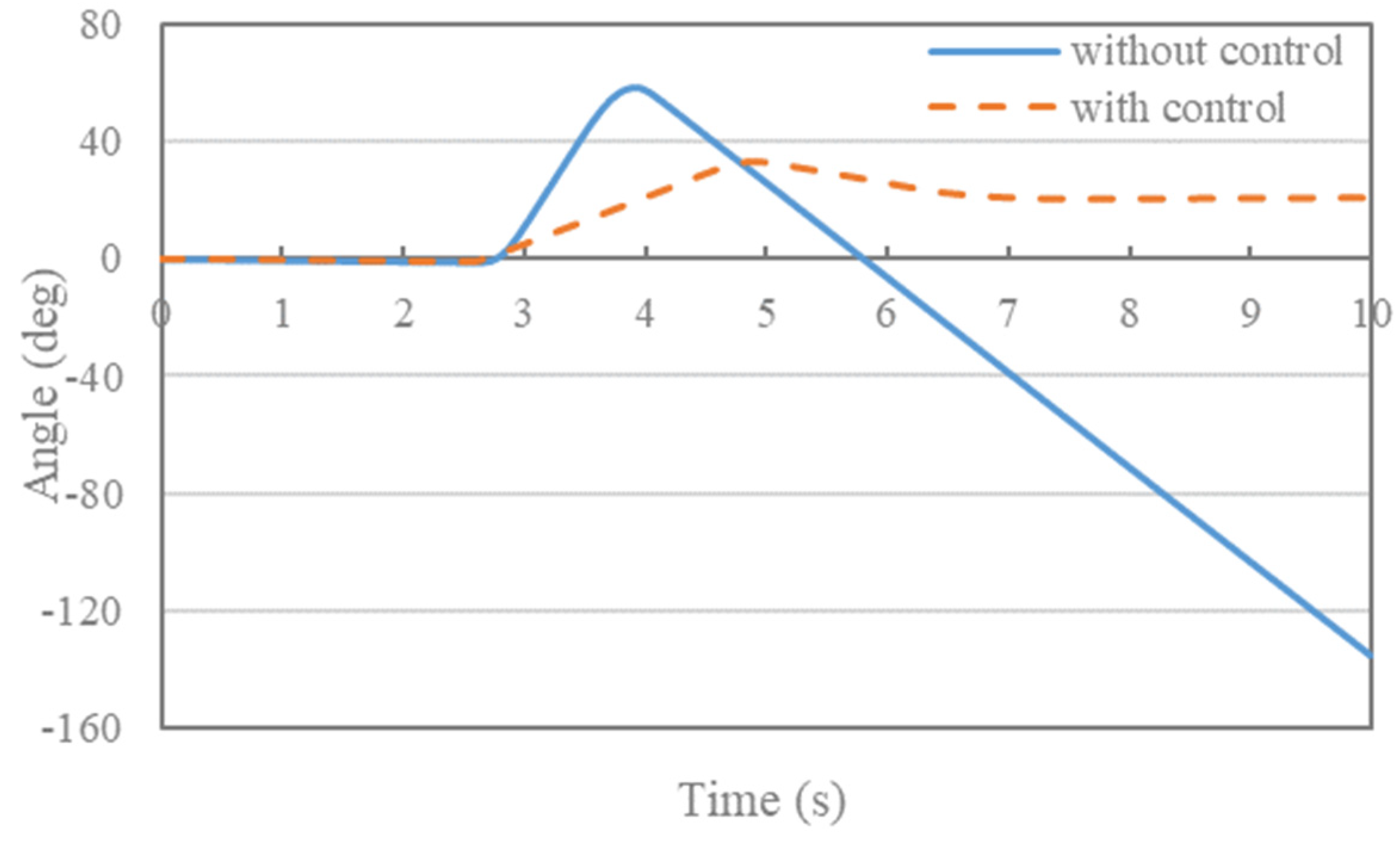
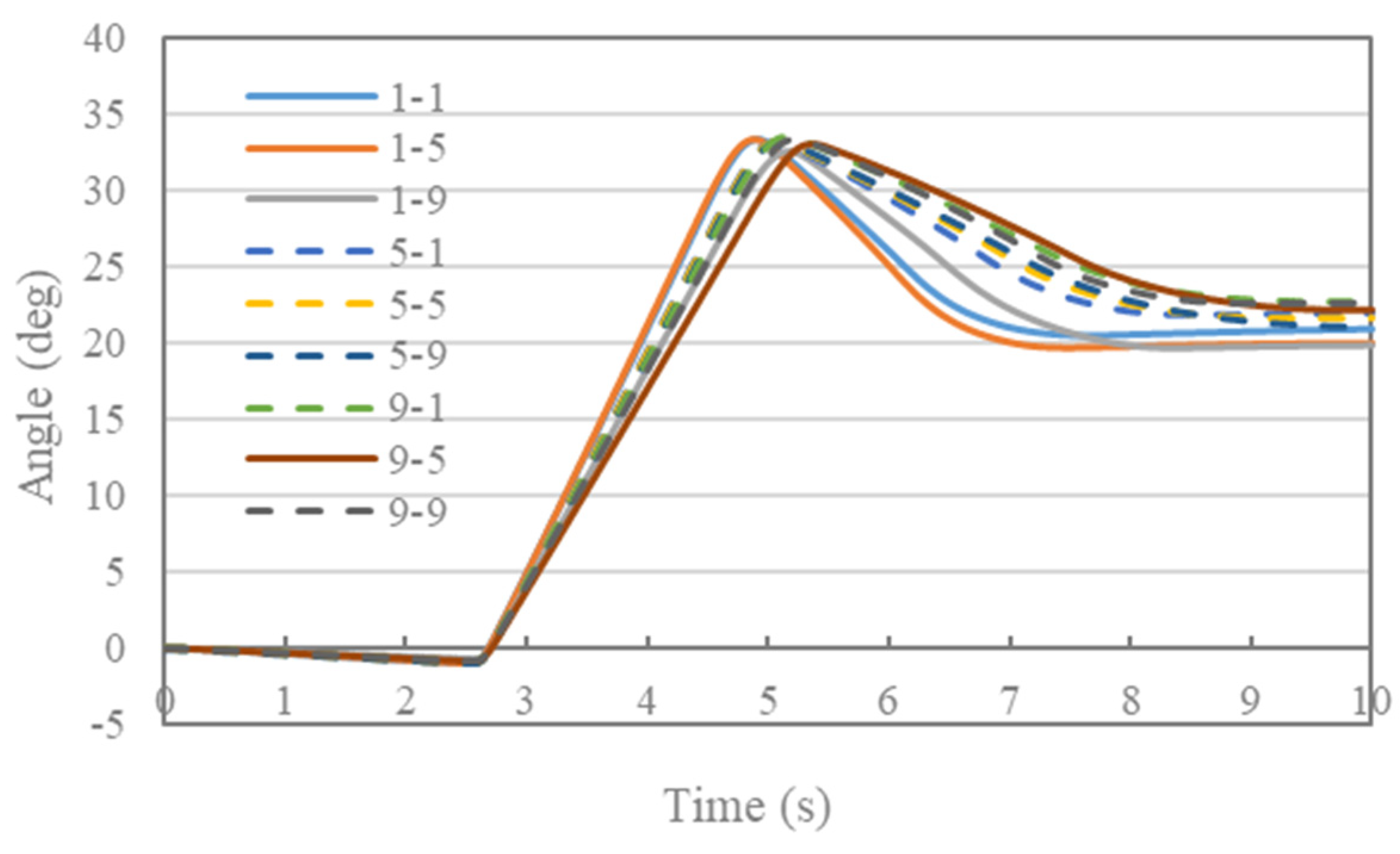
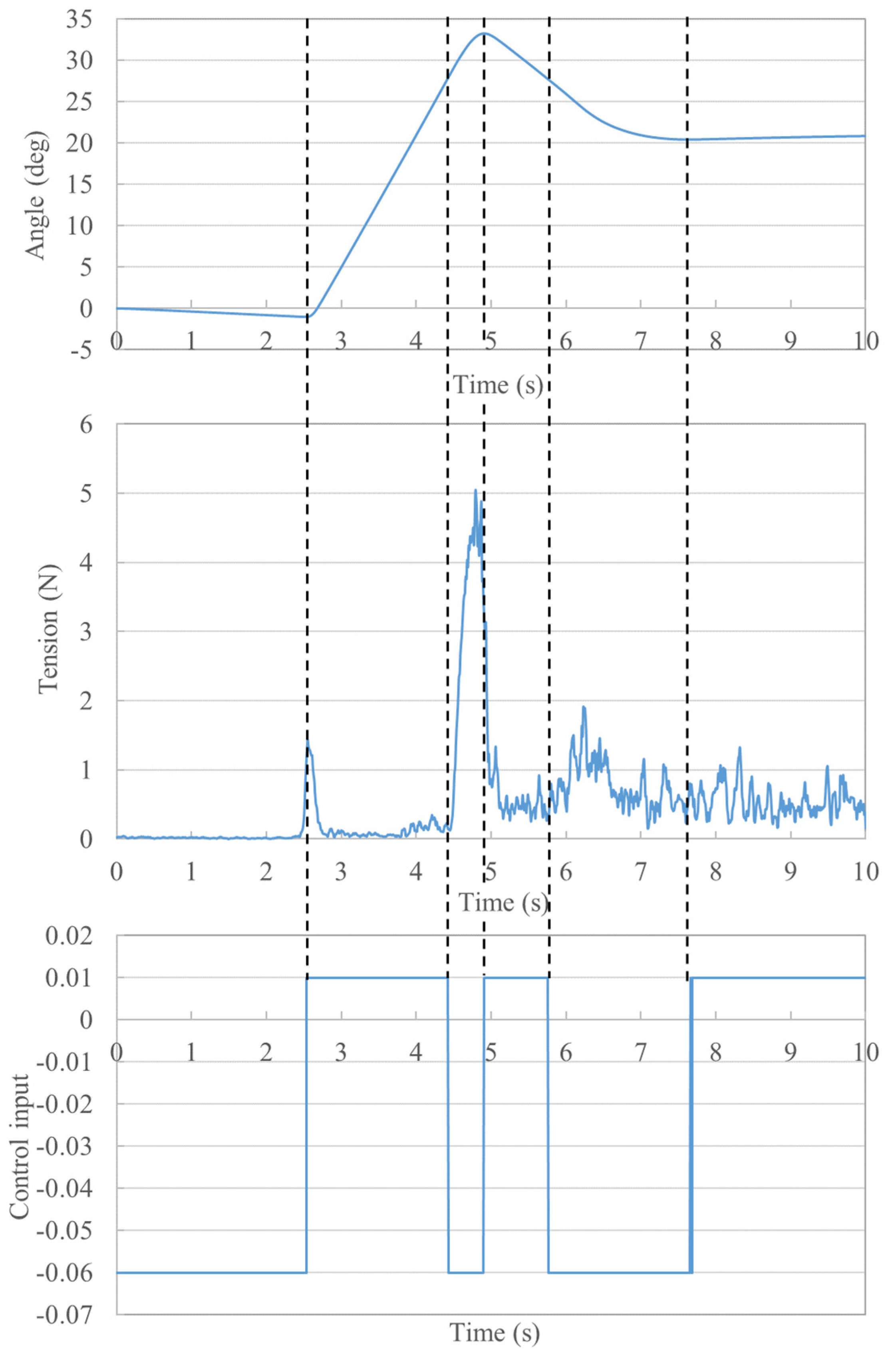
3.2. Examination of Control Effect
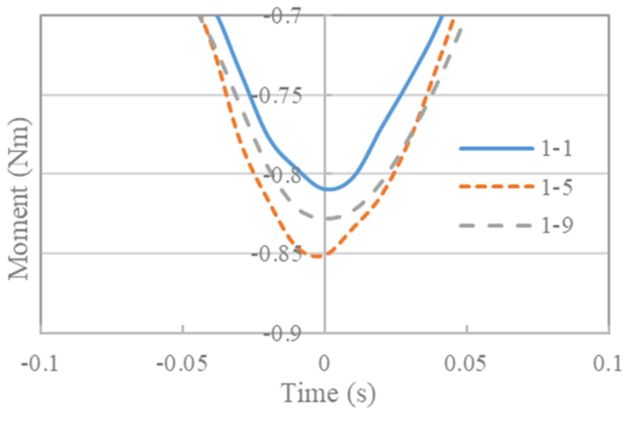
4. Mechanism of Effect of Slit Shape on Control Responsiveness
5. Conclusions
Author Contributions
Funding
Institutional Review Board Statement
Informed Consent Statement
Data Availability Statement
Conflicts of Interest
References
- Modi, V.J.; Misara, A.K. On the deployment of tether connected two-body systems. Acta Astronutica 1979, 6, 1183–1197. [Google Scholar] [CrossRef]
- Nohmi, M. Space verification experimental analysis for attitude control of a tethered space robot. Trans. JSME 2014, 80, SE0282. [Google Scholar]
- Takehara, S.; Nishizawa, T.; Kawarada, M.; Hase, K.; Terumichi, Y. Development of Tether Space Mobility Device. Comput. Methods Appl. Sci. 2014, 35, 255–274. [Google Scholar]
- Carrier, G.F. The Spaghetti Problem. Am. Math. Mon. 1949, 56, 669–672. [Google Scholar] [CrossRef]
- Shabana, A.A. Dynamics of Multibody Systems, 3rd ed.; Cambridge University Press: Cambridge, UK, 2005. [Google Scholar]
- Wago, T.; Kobayashi, N.; Sugawara, Y. Improvement on evaluating axial elastic force in beam element based on the absolute nodal coordinate formulation by accurate mean axial strain measure. Trans. Jpn. Soc. Mech. Eng. 2013, 79, 2704–2713. (In Japanese) [Google Scholar] [CrossRef] [Green Version]
- Berzeri, M.; Shabana, A.A. Development of simple models for the elastic forces in the absolute nodal co-ordinate formulation. J. Sound Vib. 2000, 235, 539–565. [Google Scholar] [CrossRef]
- Shabana, A.A. Dynamics of Multibody Systems, 2nd ed.; Cambridge University Press: Cambridge, UK, 1998. [Google Scholar]
- Takehara, S.; Kawarada, M.; Hase, K. Dynamic Contact between a Wire Rope and a Pulley Using Absolute Nodal Coordinate Formulation. Machines 2016, 4, 4. [Google Scholar] [CrossRef] [Green Version]
- Kobayashi, N.; Komaki, Y.; Watanabe, M. Effect of gap size at inlet on spaghetti problem. Trans. Jpn. Soc. Mech. Eng. 2001, 67, 641–647. (In Japanese) [Google Scholar] [CrossRef] [Green Version]
- Takehara, S.; Uematsu, Y.; Miyaji, W. Tether Space Mobility Device Attitude Control during Tether Extension and Winding. Machines 2018, 6, 4. [Google Scholar] [CrossRef] [Green Version]
- Sato, S.; Tao, K.; Nohmi, M.; Yamagiwa, Y.; Aoki, Y.; Ootsuka, K.; Ishikawa, Y. Analysis of tether deployment dynamics of tether microsatellite system. In Proceedings of the Space Transportation Symposium FY2016, Sagamihara, Japan, 19–20 January 2017; pp. 1–6. [Google Scholar]


| Condition | ||
|---|---|---|
| 1-1 | 1 | 1 |
| 1-5 | 1 | 5 |
| 1-9 | 1 | 9 |
| 5-1 | 5 | 1 |
| 5-5 | 5 | 5 |
| 5-9 | 5 | 9 |
| 9-1 | 9 | 1 |
| 9-5 | 9 | 5 |
| 9-9 | 9 | 9 |
| Parameter | Value |
|---|---|
| Total length of tether, (m) | 2.5 |
| Diameter of tether, (m) | 5.2 × 10⁻⁴ |
| Density of tether, (kg/m3) | 1140 |
| Transverse elastic modulus, (GPa) | 1.93 |
| Longitudinal elastic modulus, (GPa) | 1.93 |
| Number of tether elements, | 50 |
| Mass of inlet, (kg) | 0.0367 |
| Mass of TSMD part, (kg) | 0.8172 |
| Mass of human analog, (kg) | 7.78 |
| Moment of inertia of inlet, (kg·m2) | 9.4 × 10⁻⁶ |
| Moment of inertia of TSMD part, (kg·m2) | 2.6 × 10⁻³ |
| Moment of inertia of human analog, (kg·m2) | 0.0548 |
| Length of inlet, (m) | 0.055 |
| Length of TSMD part (m) | 0.17 |
| Length of human analog (m) | 0.19 |
| Width of inner wall (m) | 0.0015 |
| Width of TSMD part (m) | 0.095 |
| Width of human analog (m) | 0.22 |
| Control input | 0.01 |
| Control input | −0.06 |
| Spring constant of inner wall, (N/m) | 100 |
| Spring constant of edge, (N/m) | 100 |
| Damping coefficient of inner wall, (N/(m/s)) | 0.0696 |
| Damping coefficient of edge, (N/(m/s)) | 0.0696 |
| Coefficient of friction of inner wall of inlet, | 0.1 |
| Coefficient of friction of edge of inlet, | 0.1 |
| Coefficient of friction of inner wall of TSMD part | 0.0 |
Publisher’s Note: MDPI stays neutral with regard to jurisdictional claims in published maps and institutional affiliations. |
© 2021 by the authors. Licensee MDPI, Basel, Switzerland. This article is an open access article distributed under the terms and conditions of the Creative Commons Attribution (CC BY) license (https://creativecommons.org/licenses/by/4.0/).
Share and Cite
Takayama, S.; Takehara, S.; Yuasa, R. Contact Analysis of Mobility Devices Based on Tension. Modelling 2021, 2, 370-384. https://doi.org/10.3390/modelling2030020
Takayama S, Takehara S, Yuasa R. Contact Analysis of Mobility Devices Based on Tension. Modelling. 2021; 2(3):370-384. https://doi.org/10.3390/modelling2030020
Chicago/Turabian StyleTakayama, Satoshi, Shoichiro Takehara, and Ryota Yuasa. 2021. "Contact Analysis of Mobility Devices Based on Tension" Modelling 2, no. 3: 370-384. https://doi.org/10.3390/modelling2030020
APA StyleTakayama, S., Takehara, S., & Yuasa, R. (2021). Contact Analysis of Mobility Devices Based on Tension. Modelling, 2(3), 370-384. https://doi.org/10.3390/modelling2030020