Communication

Quantum Mechanical Comparison between Lithiated and Sodiated Silicon Nanowires

Nanoscience Research Institute, Arlington, VA 22314, USA
Appl. Nano 2024, 5(2), 48-57; https://doi.org/10.3390/applnano5020005
Submission received: 21 December 2023 / Revised: 18 March 2024 / Accepted: 20 March 2024 / Published: 1 April 2024
(This article belongs to the Collection Feature Papers for Applied Nano)

Abstract

:
This computational research study will compare the specific charge capacity (SCC) between lithium ions inserted into crystallized silicon (c-Si) nanowires with that of sodium ions inserted into amorphous silicon (a-Si) nanowires. It will be demonstrated that the potential energy V(r) within a lithium–silicon nanowire supports a coherent energy state model with discrete electron particles, while the potential energy of a sodium–silicon nanowire will be discovered to be essentially zero, and, thus, the electron current that travels through a sodiated silicon nanowire will be modeled as a free electron with wave-like characteristics. This is due to the vast differences in the electric fields of lithiated and sodiated silicon nanowires, where the electric fields are of the order of 10 10 V/m and 10 15 V/m, respectively. The main reason for the great disparity in electric fields is the presence of optical amplification within lithium ions and the absence of this process within sodium ions. It will be shown that optical amplification develops coherent optical interactions, which is the primary reason for the surge of specific charge capacity in the lithiated silicon nanowire. Conversely, the lack of optical amplification is the reason for the incoherent optical interactions within sodium ions, which is the reason for the low presence of SCC in sodiated silicon nanowires.

1. Introduction

For over a decade, lithium ion batteries (LIBs) have been a commercial success for consumer electronics and electric vehicles. However lithium is a relatively strategic and precious metal that will be limited due to increased use by developing countries as we advance into the 21st century. Sodium ion (Na+) batteries have created attention due to the abundance of Na worldwide. Similarly to the lithium atom, Na is a Rydberg atom (one electron in the outer atomic orbit), although the sodium atom is larger than lithium [1].
One of the original commercial LIB designs in the 1990s used a carbon-base anode material for various energy storage devices with a specific charge capacity (SCC) of approximately 400 mAh/g [2]. In order to improve the SCC of lithium ion batteries, crystallized silicon (c-Si) has been studied as a possible substitute anode material instead of carbon. The SCC of lithiated silicon has been found by several research studies to be over 4000 mAh/g, which has made c-Si anode material for lithium ions very popular in LIB research [3]. Unfortunately, as was discovered during the course of this research, the insertion of lithium ions into crystallized silicon produces an extremely large anisotropic volume expansion in the range of 300 to 400 percent of the lithiated silicon nanowire’s original volume [4]. This volume expansion leads to an overall decrease in the specific charge capacity and, ultimately, the failure of this LIB component [5]. Research using MD/DFT simulations [6] has uncovered problems that have not been overcome in the design and manufacturing of lithiated silicon batteries for commercial use.
Concurrently with the research on the insertion of lithium ions into crystallized silicon, the study of the insertion of sodium ion into the same anode material of c-Si was performed. In this research, the formation energy of sodium–silicon N a x S i was found to be significantly lower than that of lithium–silicon L i x S i (where x is the ratio of lithium or sodium ions to silicon atoms) [7]. This caused the crystallized silicon to be nonreactive to sodium ions and, therefore, a poor anode material [8]. During this time, amorphous silicon (a-Si) was substituted for crystallized silicon (c-Si) in sodium ion/silicon research. It was discovered that a-Si had a formation energy that was substantially higher than that of c-Si when sodium ions were inserted, and, therefore, amorphous silicon could possibly be used as an anode material for batteries [9]. As a result, this research will compare the reactions between L i + /c-Si and N a + /a-Si materials.
Two theoretical in situ apparatuses will be the focus of this research—one for a lithium ion/crystallized silicon (c-Si) nanowire and the other for a sodium ion/amorphous silicon (a-Si) nanowire, as displayed in Figure 1a,b. Prior to the beginning of the lithiation of the c-Si nanowire and the sodiation of the a-Si nanowire, the individual lithium and sodium atoms are ionized, reducing them to their constitutive particles of lithium/sodium ions and free electrons. Each silicon nanowire is part of a separate electric series circuit with a constant voltage of 2 V that is applied to each nanowire in order to diffuse lithium and sodium ions through their respective nanowires. In both lithiated and sodiated silicon nanowires, the electrons and lithium/sodium ions enter the c-Si and a-Si silicon nanowire, respectively, at opposing ends and, therefore, travel in opposite directions. Since the electrons and ions are moving charge particles, they are the source of the electric fields. The c-Si nanowire is composed of a diamond crystalline cubic structure, as shown in Figure 1c, whereas the a-Si nanowire is composed of the same number of silicon atoms, albeit in a random formation.

2. Electric Fields

In order to define the induced electric fields for lithiated and sodiated silicon nanowires, the wavefunctions must first be derived for each of the constitutive particles presented in this study. The ion diffusion and electron current within the silicon nanowires are assumed to be a continuous uniform flow with minimal temporal variations. For this reason, the time-independent Schrodinger equation will be used to solve the wavefunctions for lithium, sodium, and silicon.
h ¯ 2 2 m e f f 2 + V r Ψ B r = E Ψ B r
where h ¯ is Planck’s constant, m e f f is the effective mass of the electron, E is the eigenvalue, and V(r) is the potential energy. The ground-state wavefunctions that will be used for lithium ions and silicon atoms are
Ψ B r , θ , ϕ = N r n 1 exp [ Z eff a ¯ o n ] Y l m ( θ , ϕ )
a ¯ o = r a o
where r , θ , ϕ are the spherical coordinates, n is the energy level, Z e f f is the effective atomic number, N is the normalization constant, a o is the Bohr radius, and Y l m ( θ , ϕ ) represents the spherical harmonics. The subscript B denotes the type of wavefunction that will be used, which will be that of lithium ions ( L i + ) and silicon atoms (c-Si, a-Si). The wavefunctions Ψ L i ,   Ψ c _ S i , and Ψ a _ S i are calculated using the Slater determinant. The ground-state wavefunction for sodium ions Ψ N a was defined by using a harmonic oscillator wavefunction
Ψ N a = A e m e f f ω 2 h ¯ r 2
where A is the amplitude and ω is the angular frequency of the electron. In addition to Equation (3) being a solution to the time-independent Schrodinger equation, it is also a solution to the Thomas–Fermi equation, which is part of a theoretical model for the electronic structure of atoms that is the predecessor to density functional theory [10].
d 2 Ψ N a d x 2 = Ψ N a 3 / 2 x 1 / 2
where x = 0.885 Z e f f 1 3 a o r .
The ground-state wavefunctions are embedded within the electric field equations via the Bloch function equations. This is accomplished by defining the expectation value of the wave numbers of lithium ions, sodium ions, and silicon atoms. First, the wave number expectation values for lithium ions and crystallized silicon atoms are
k L i = Ψ L i k ^ Ψ L i Ψ L i Ψ L i
k c _ S i = Ψ c _ S i k ^ Ψ c _ S i Ψ c _ S i Ψ c _ S i
where k ^ = i . The Bloch functions of lithium ions u L i r and crystallized silicon atoms u c _ S i r are defined as
u L i r = e i k L i r + 1 k L i r e i δ L i + k L i r sin δ L i + 3 z k L i r 2 e i δ L i + k L i r sin δ L i
u c _ S i r = e i k c _ S i r + 1 k c _ S i r e i δ c _ S i + k c _ S i r sin δ c _ S i + 3 z k c _ S i r 2 e i δ c _ S i + k c _ S i r sin δ c _ S i
where δ L i and δ c _ S i are defined as the phase shifts of lithium ions and crystallized silicon atoms, respectively. The Bloch functions are, in turn, a function of the electric field E L i utilizing the Drude model for electron transport within the L i + and c-Si matrix.
E L i = i C E h ¯ 2 3 π 2 n ¯ c 2 3 v D O S 4 n v e m e f f u c _ S i u L i * u c _ S i * u L i
As mentioned previously, negative free electrons and positive lithium ions enter into the silicon nanowire model from opposing directions. The electric charge difference between the constitutive particles, where the electrons are always greater or equal in number to the lithium ions in the model, will be known as the average negative charge differential n ¯ c , which is the number of charged particles per unit volume. The electric charge unit of an electron is denoted as e, n v is the electron density of the maximum valence band, v D O S is defined as the density of state volume, and the coefficient C E allows the electric field to be a solution to the Maxwell equations. The electric field E L i describes the electrons in the minimum conduction band of lithium ions. These electrons are in the lowest energy state in the conduction band, but when the majority of lithium ions enter into the excited state, population inversion occurs, and the electric field increases in strength through the optical amplification factor γ L i . As a result, the lithium ions’ electric field E L i is redefined as
E L i = E L i e x p γ L i r 2
where
γ L i r , t = σ L i · N L i
N L i = N L i N 1
σ L i = A L i L 2 8 π n L i 2 g ω
In Equation (11), N L i is the difference in the number of excited-state lithium ions N L i and the number of ground-state silicon atoms N 1 within the diamond cubic lattice. The reason for the silicon atoms being modeled in the ground state is because of the low electron transition probability in silicon atoms due to them being an indirect band-gap material [11]. Therefore, in this study, N L i = 30 and N 1 = 8 for a ratio of x = N L i / N 1 = 3.75, which is the same as the value of x in lithiated silicon L i x S i at which the silicon diamond cubic lattice in our model is considered to be at full lithiation. Equation (12) is the stimulated emission cross-section area σ L i , which is defined by the Einstein A coefficient A L i , the spectral line shape function g ω , the wavelength of the photon emitted L , and the lithium refractive index n L i . The total electric field becomes
E L i = i C E h ¯ 2 3 π 2 n ¯ c 2 3 v D O S 4 n v e m e f f u c _ S i u L i * u c _ S i * u L i e x p γ L i r 2
A similar derivation for the electric field E N a that is generated by the flow of the electron current and the insertion of sodium ions ( N a + ) into amorphous silicon (a-Si) is
k N a = Ψ N a k ^ Ψ N a Ψ N a Ψ N a
k a _ S i = Ψ a _ S i k ^ Ψ a _ S i Ψ a _ S i Ψ a _ S i
u N a r = e i k N a r + 1 k N a r e i δ N a + k N a r sin δ N a + 3 z k N a r 2 e i δ N a + k N a r sin δ N a
u a _ S i r = e i k a _ S i r + 1 k a _ S i r e i δ a _ S i + k a _ S i r sin δ a _ S i + 3 z k a _ S i r 2 e i δ a _ S i + k a _ S i r sin δ a _ S i
γ N a r , t = σ N a · N N a
N N a = N N a N 1
σ N a = A N a λ 2 8 π n N a 2 g ω
E N a = i C E h ¯ 2 3 π 2 n ¯ c 2 3 v D O S 4 n v e m e f f u a _ S i u N a * u a _ S i * u N a e x p γ N a r 2
For the sodium ions/amorphous silicon nanowire model, the full sodiation is at x = 0.75 for sodiated silicon N a x S i . This translates into N N a = 6 for the excited-state N a + ions and N 1 = 8 for the ground-state a-Si atoms for a ratio of x = N N a / N 1 . As stated previously, in order for optical amplification γ to occur, at least half of the atoms/ions in the system must be in the excited state. This does not happen, since x is less than one. Therefore, optical amplification does not occur, and γ N a 0 for sodium ions.
A comparison of the two electric fields of E L i and E N a that are generated by lithium ions and sodium ions as they are inserted into their respective silicon nanowires is displayed in Figure 2 and Figure 3. Both electric fields are generated by opposing electron currents traveling counter to lithium ion diffusion in Figure 1a and sodium ion diffusion in Figure 1b. The electron currents (where the silicon lattice constant is a) are defined as
I L i = 2 n ¯ c 1 / 3 a 2 e 2 E L i h ¯ 3 π 2 2 / 3
I N a = 2 1 / 2 e a 1 / 3 ω e w 3 π 2 1 / 3 N ¯ c
ω e w = 3 n ¯ c a 3 h ¯ k a S i m e f f ψ e w
ψ e w = N 1 2 2 π 1 4 e r a 2 e i k r
The sodium electron current I N a is defined by the electron wave’s angular frequency ω e w , which is a function of the electron wavefunction ψ e w [12]. The number of electrons is represented by N ¯ c . The electric field E L i in the computational model of the Li/c-Si nanowire is of a magnitude between 10 9   t o   10 10 volt/meters, while the electric field E N a in the N a + /a-Si nanowire model is 10 16   t o   10 15 V/m. The potential energy V r within the Hamiltonians representing both models is directly proportional to the electric fields. Since the electric field is greater in the lithiated silicon nanowire than in the sodiated silicon nanowire, the energy states within each nanowire will be modeled differently based on quantum mechanical theory. For the L i + /c-Si model, the discrete energy states of a quantum harmonic oscillator will be utilized for the electron current and lithium ions within the c-Si nanowire. However, since the potential energy V r in the N a + /a-Si model is approximately zero, the electron current will be modeled as free electrons that are unrestricted from the potential energy as they travel through the a-Si nanowire. This gives the electron current within the N a + /a-Si nanowire model wavelike characteristics, as opposed to the electron current within the L i + /c-Si nanowire, where the electrons exist not as waves but as particles and only at discrete energy levels (Equations (21)–(23)).

3. Degree of Coherence

The electric field in each silicon nanowire will be analyzed in terms of the quantum optical interactions. These interactions are between the photons in the lithiated silicon nanowires and between the electric waves in the sodiated silicon nanowires. These quantum optical interactions are described by three types of interference: coherent, incoherent, and mixed interactions. From these interferences, a set of phase-matching conditions will be established:
Phase-Matching Conditions:
(1)
Coherent Optical Interactions: ω c = i = 1 M ω i = M ω
Constructive Interference where the values of ω i are equal and are in phase
(2)
Incoherent Optical Interactions: ω c = i = 1 M ω i 0
Destructive Interference where the values of ω i are not equal and are not in phase
(3)
Mixed Optical Interactions: ω c = i = 1 M ω i 0
Partial Destructive Interference is a combination of coherent and incoherent interactions.
M is the total number of particles (for lithium) or wave amplitudes (for sodium) for each interaction, and ω c is called the coherent angular frequency and will be defined in Equations (26) and (32).
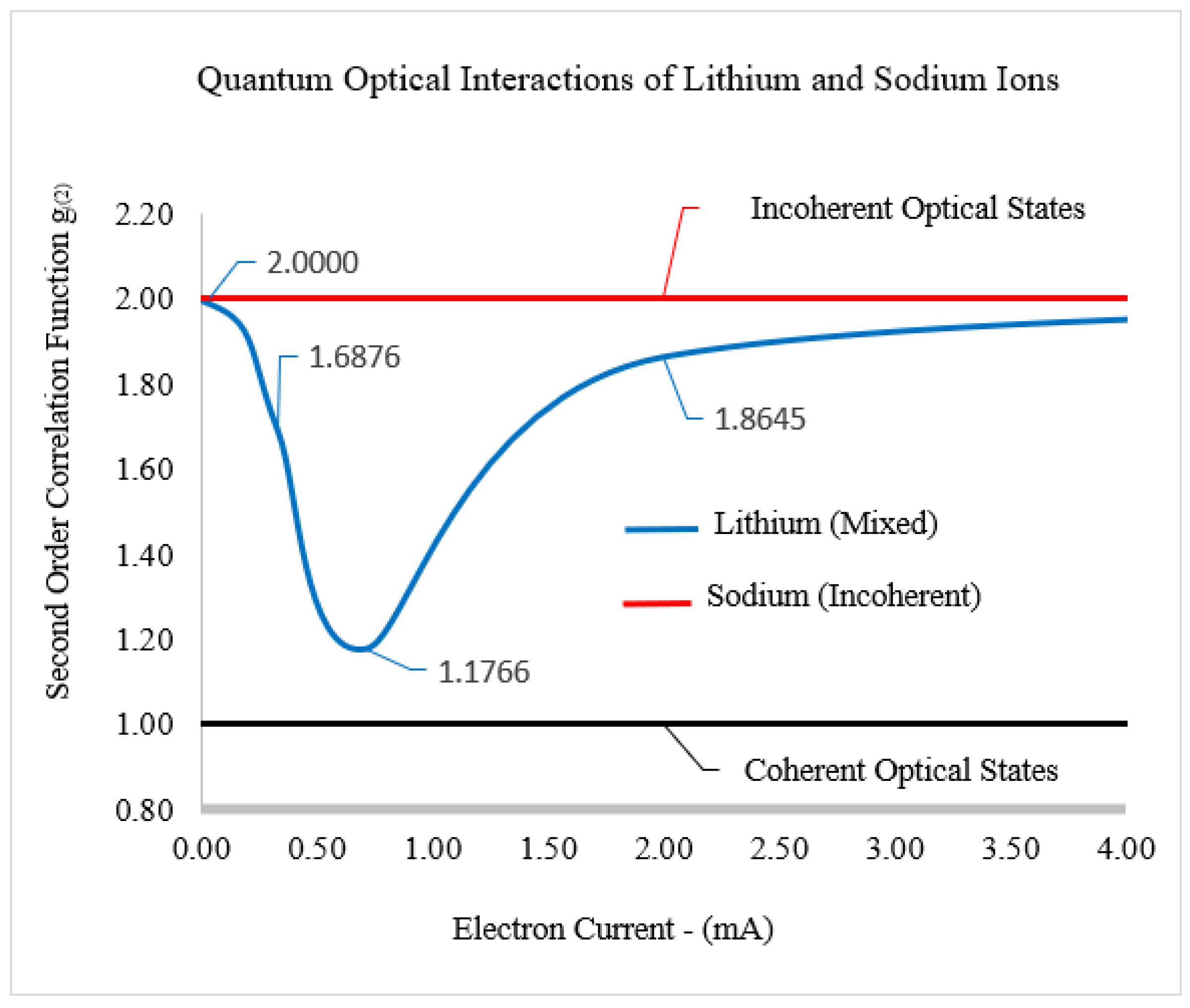
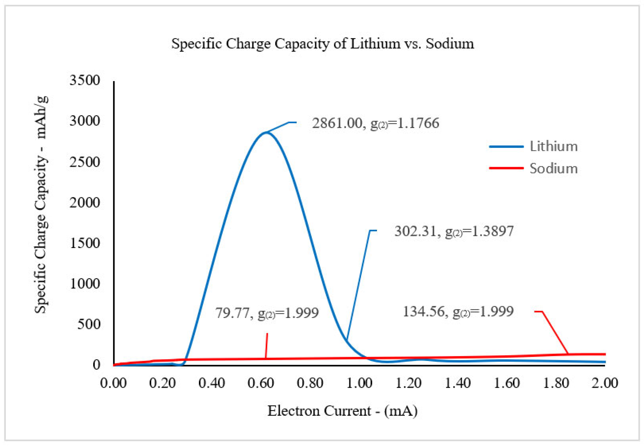
According to the phase-matching conditions, the coherent optical states for each electric field will be the focus when determining the specific charge capacity (SCC) for the lithiated and sodiated silicon nanowires with respect to the electron current. The second-order correlation function g 2 will be used to calculate the degree of coherence, which, in this study, is defined as the measure of the amount of coherent interference for the electric fields. For the lithium ion electric field, g L i 2 is defined as [13]
g L i 2 = 1 + e x p π α L i 2
where
α L i = ω c _ L i ω γ _ L i
ω c _ L i = ω e _ L i λ L i
ω γ _ L i = a 3 2 h ¯ n L i 2 E L i 2
ω e _ L i = e E L i h ¯ 3 π 2 n ¯ c 1 3
λ L i = a 2 m e f f 3 2 ω e L i 3 2 2 π h ¯ 1 2 e E L i t c e x p Δ r n L i Ψ L i e Ψ L i e
and for the sodium ion electric field, the second-order correlation function is
g N a 2 = 1 + e x p π α N a 2
α N a = ω c _ N a ω γ _ N a
ω c _ N a = ω e _ N a λ N a
ω γ _ N a = a 3 2 h ¯ n N a 2 E N a 2
ω e _ N a = e E N a h ¯ 3 π 2 n ¯ c 1 3
λ N a = a 2 m e f f 3 / 2 ω e _ N a 3 / 2 2 π h ¯ 1 / 2 e E N a t c e x p Δ r n N a Ψ N a e Ψ N a e
In Equations (25) and (31), α L i and α N a are defined as the ratio of the coherent angular frequency ω c _ L i or ω c _ N a for lithium or sodium to the total electric angular frequency ω γ _ L i or ω γ _ N a for lithium or sodium, respectively. Equations (28) and (34) describe the angular frequencies ω e _ L i   a n d   ω e _ N a for electron particles in L i + /c-Si and electron waves in N a + /a-Si, respectively. The lambda functions λ L i   a n d   λ N a for lithiated and sodiated silicon nanowires are stated in Equations (29) and (35), which were derived from the quantum mechanical path integral method [14]. The lambda functions of λ L i   a n d   λ N a are Gaussian equations that are dependent on the transition state vector Δ r , which is defined as the transitional length from an initial state to a final state of a wavefunction. The excited-state wavefunction for lithium ions Ψ L i e and sodium ions Ψ N a e are constructed by using time-independent perturbation theory; the coherence time is t c , and the refractive indices are n L i and n N a for lithium and sodium, respectively.
The relationships between the second-order correlation functions g L i 2 and g N a 2 are displayed in Figure 4. In general, when g 2 ω = 1 , the electric field is in a coherent optical state, and conversely, when g 2 ω = 2 , the electric field is in an incoherent optical state. The mixed optical state is defined as 1 < g 2 ω < 2 . When the second-order correlation functions are in the mixed optical state for lithiated silicon, the shape of g L i 2 is an inverted Gaussian function, where the low point of the function is g L i 2 = 1.1766 .

4. Specific Charge Capacity

The coherent optical interactions that are produced from the electric fields during optical amplification are directly proportional to the specific charge capacity (SCC) of the lithium and sodium silicon nanowires.
S C C L i = 1 + ϵ L i ω c _ L i ω L i N ¯ c N ¯ L i e m L i
S C C N a = 1 + ϵ N a ω c _ N a ω N a N ¯ c N ¯ N a e m N a
where ϵ L i and ϵ N a are the volumetric strain for lithiated and sodiated silicon nanowires, respectively. The volumetric strains are constant in this study because both silicon nanowires are at their maximum volume during the computational analysis [15]. The minimum g L i 2 is related to the maximum SCC for lithium, as shown in Figure 4 and Figure 5. The second-order correlation function g L i 2 is inversely proportional to the specific charge capacity S C C L i . The result is that the coherent optical state within the lithiated silicon nanowire increases due to the optical amplification process, which leads to an increase in lithium’s specific charge capacity S C C L i . Since optical amplification does not occur within the sodiated silicon nanowire, the Gaussian function λ N a for sodium is ‘flat’, and as a result, sodium’s S C C N a is significantly lower than lithium’s S C C L i (Figure 5).

5. Summary

In this study, we examined the quantum mechanical properties of the insertion of lithium and sodium ions into crystallized and amorphous silicon nanowires, respectively, with an electron current flowing in a direction opposing that of ion diffusion. It has been demonstrated through computational analysis that lithiated silicon can generate a large electric field E L i that includes optical amplification. Conversely, the computational analysis predicts that the electric field E N a inside a sodiated silicon nanowire is extremely weak, with no optical amplification. With the vastly different magnitudes of the electric fields in each silicon nanowire, the electron current in lithiated silicon was modeled as electron particles from a large coherent energy state system, and the sodiated silicon electron current was modeled as electron waves because the potential energy was calculated to be approximately zero. The optical amplification is the reason for the high levels of specific charge capacity S C C L i in lithiated silicon as a result of the process of the coherent optical interaction generated by the electric field E L i . Since optical amplification does not develop in sodiated silicon, incoherent optical interactions are predominately present in sodiated silicon, and extremely low levels of the S C C N a are present in sodium ion silicon nanowires.

Funding

This research received no external funding.

Data Availability Statement

The data presented in this study are available in the article.

Conflicts of Interest

The author declares no conflict of interest.

References

  1. Chou, C.Y.; Lee, M.; Hwang, G.S. A Comparative First-Principles Study on Sodiation of Silicon, Germanium, and Tin for Sodium-Ion Batteries. J. Phys. Chem. C 2015, 119, 564–573. [Google Scholar] [CrossRef]
  2. Liu, X.H.; Zheng, H.; Zhong, L.; Huang, S.; Karki, K.; Zhang, L.Q.; Liu, Y.; Kushima, A.; Liang, W.T.; Wang, J.W.; et al. Anisotropic Swelling and Fracture of Silicon Nanowires during Lithiation. Nano Lett. 2011, 11, 3312–3318. [Google Scholar] [CrossRef]
  3. Huang, S.; Zhu, T. Atomistic mechanisms of lithium insertion in amorphous silicon. J. Power Sources 2011, 196, 3664–3668. [Google Scholar] [CrossRef]
  4. Yang, H.; Huang, S.; Huang, X.; Fan, F.; Liang, W.; Liu, X.H.; Chen, L.-Q.; Huang, J.Y.; Li, J.; Zhu, T.; et al. Orientation-Dependent Interfacial Mobility Governs the Anisotropic Swelling in Lithiated Silicon Nanowires. Nano Lett. 2012, 12, 1953–1958. [Google Scholar] [CrossRef] [PubMed]
  5. Boone, D.C. Maxwell stress to explain the mechanism for the anisotropic expansion in lithiated silicon nanowires. AIP Adv. 2016, 6, 125–133. [Google Scholar] [CrossRef]
  6. Jung, S.C.; Choi, J.W.; Han, Y.K. Anisotropic Volume Expansion of Crystalline Silicon during Electrochemical Lithium Insertion: An Atomic Level Rationale. Nano Lett. 2012, 12, 489–498. [Google Scholar] [CrossRef]
  7. Arrieta, U.; Katcho, N.A.; Arcelus, O.; Carrasco, J. First-Principles Study of Sodium Intercalation in Crystalline NaxSi24 (0 ≤ x ≤ 4) as Anode Material for Na-ion Batteries. Sci. Rep. 2017, 7, 289–301. [Google Scholar] [CrossRef] [PubMed]
  8. Boone, D.C. Quantum Coherent States and Path Integral Method to Stochastically Determine the Anisotropic Volume Expansion in Lithiated Silicon Nanowires. Math. Comput. Appl. 2017, 22, 41. [Google Scholar] [CrossRef]
  9. Jung, S.C.; Jung, D.S.; Choi, J.W.; Han, Y.K. Atom-Level Understanding of the Sodiation Process in Silicon Anode Material. J. Phys. Chem. Lett. 2014, 5, 340–351. [Google Scholar] [CrossRef]
  10. Desaix, M.; Anderson, D.; Lisak, M. Variational approach to the Thomas–Fermi equation. Eur. J. Phys. 2004, 218, 303–307. [Google Scholar] [CrossRef]
  11. Fox, M. Quantum Optics: An Introduction; Oxford University Press: Oxford, UK, 2008; pp. 256–257. [Google Scholar]
  12. Tai-Wang, C.; Yan-Li, X.; Xiao-Feng, L.; Ling-An, W.; Pan-Ming, F. Electronic Wave Packet in a Quantized Electromagnetic Field. Chin. Phys. Lett. 2002, 19, 1792. [Google Scholar]
  13. Gilbert, M.J.; Akis, R.; Ferry, D.K. Scattering in Quantum Simulations of Silicon Nanowire Transistors. Inst. Phys. Publ. J. Phys. Conf. Ser. 2006, 35, 219–232. [Google Scholar] [CrossRef]
  14. Ciraci, S.; Buldum, A.; Batra, I.P. Quantum effects in electrical and thermal transport through nanowires. J. Phys. Condens. Matter 2001, 13, 178–188. [Google Scholar] [CrossRef]
  15. Boone, D.C. Reduction of Anisotropic Volume Expansion and the Optimization of Specific Charge Capacity in Lithiated Silicon Nanowires. World J. Nano Sci. Eng. 2019, 9, 15–24. [Google Scholar] [CrossRef]
Figure 1. Arrangement of the in situ apparatus for a solid electrochemical cell using (a) a lithium metal counter electrode (Li) and (b) a sodium metal counter electrode (Na), each with an applied voltage source of 2 V. (c) Silicon is a diamond crystalline cubic structure made up of tetrahedral molecules, and its hybridized s p 3 orbitals within their valence shells are filled with covalent bonding electrons from neighboring silicon atoms.
Applnano 05 00005 g001
Figure 2. The electric fields that are generated within the lithiated and sodiated silicon nanowires. The lithium ion electric field E L i is of a magnitude between 10 9   t o   10 10 V/m, whereas the sodium ion electric field E N a is of a magnitude 10 15 V/m and, therefore, is approximately zero ( E N a 0 ).
Applnano 05 00005 g002
Figure 3. The sodium ion electric field E N a has a wavelike characteristic at the quantum level and is approximately zero. Since the potential energy V r is a function of E N a , the electrons that travel within the N a + /a-Si nanowire can be modeled as a quantum electron wave that is subjected to a potential energy of V r = 0 .
Applnano 05 00005 g003
Figure 4. The second-order correlation functions g 2 for lithiated and sodiated silicon are displayed. Lithium is in the mixed optical state since 1 < g L i 2 < 2 , but g N a 2   2; therefore, it is defined as being in the incoherent optical state.
Applnano 05 00005 g004
Figure 5. Comparing the specific charge capacity of the diffusion of lithium ions versus sodium ions into silicon nanowires. Lithiated silicon has a large surge of energy at approximately 0.60 milliamps, which manifests as S C C L i = 2861 mAh/g due to the optical amplification that develops a majority of coherent optical interactions. However, sodiated silicon with optical amplifications of approximately zero develops mostly incoherent optical interactions and, as a result, low amounts of specific charge capacity ( S C C N a = 79.77 mAh/g at 0.60 mA).
Applnano 05 00005 g005
Disclaimer/Publisher’s Note: The statements, opinions and data contained in all publications are solely those of the individual author(s) and contributor(s) and not of MDPI and/or the editor(s). MDPI and/or the editor(s) disclaim responsibility for any injury to people or property resulting from any ideas, methods, instructions or products referred to in the content.

