1. Introduction
Optics and photonics are key-enabling technologies which are gaining a great attention in the last years. The increasing number of Master studies in optics and photonics proves that light-based technologies are paramount [
1]. Not by chance, UNESCO declared 2015 as the International Year of Light and Light-Based Technologies.
The European Higher Education Area promotes the competency-based approach proclaimed by the Bologna principles [
2]. 3 out of 10 key competences identified were the following:
Obviously, competences in maths, science and technology are essential in scientific and technical careers. Digital competence is key to being able to access the job market today (this competence is probably easier to get for young, digital natives). Learning to learn is also paramount, since knowledge must be refreshed frequently due to rapid development in any field nowadays.
On the other hand, the need to develop practical skills is essential in any discipline in general, but even more important in technical and scientific careers. “Learning by doing” is much more efficient than just passive learning [
3,
4]. To get this practical experience, hands-on experiments in the laboratory are crucial, and many initiatives are being develop to run optics and photonics experiments in all educational levels [
5,
6].
In this regard, virtual and/or remote experimentation is an invaluable tool [
7]. A virtual laboratory offers the user to simulate experiments using software-based mathematical models. Experiments can be run locally or across the Web. A remote laboratory allows the learner to interact with real, hardware instruments located physically at distant facilities. Some platforms include software-based simulation of experiments, as well as remote experimentation using real data acquisition. These Virtual Remote Labs (VRLs) allow the students to compare the experimental results with the “theoretical” ones provided by the simulations. Several VRLs in optics and photonics have been developed in the last years [
8,
9,
10,
11].
This paper presents a software tool developed to be used by engineering students as a virtual laboratory in optics and photonics. The tool, named OPTILAB, was originally intended to complement the experiments in the on-site, physical laboratory. The results obtained with previous versions of this tool, in addition to on-site teaching were already presented [
4]. Feedback obtained from students and instructors was used to improve the interface and functionality of the tool. Due to COVID-19 pandemic, OPTILAB was used to replace the on-site lab in a case study, as presented below.
The rest of this paper is organized as follows:
Section 2 describes in short the optical diffraction concepts useful in this work. The tool interface is described in
Section 3. A case study of the use of OPTILAB replacing the on-site lab session due to COVID-19 is described in
Section 4.
Section 5 discusses the results obtained in the case study, and finally
Section 6 concludes this paper.
2. A Short Review of Diffraction
Diffraction is one of the phenomenon that clearly shows the wave behaviour of light [
12]. First observed by Francesco Grimaldi in 1665, he noticed that when a travelling beam of light finds an obstacle small enough, the output beam spreads out, producing an interference pattern. Later it was observed that diffraction not only occurs in small slits or holes but also where light waves bend round a corner. This phenomenon is not only limited to light waves; it also happens in other types of waves, including sound, water and radio waves, to name a few. Diffraction can be explained using Huygens’ principle. When a travelling beam of light is partially blocked, the emerging wavelets which belong to the exposed parts superpose, in such a wave that the resulting output waveform has a different shape. This allows bending of light around the edges of the obstacle, and a fringe pattern can be seen on a screen placed afterwards.
Two types of diffraction regimes can be distinguished:
Fraunhofer diffraction (on behalf of Joseph von Fraunhofer), or far-field diffraction, is a form of wave diffraction that occurs when the projection screen is placed at a long distance from the obstacle. The shape of the diffraction pattern observed remains the same, only the size changes depending on the distance between the aperture and the projection screen.
Fresnel diffraction, or near-field diffraction, is a type of diffraction that occurs when a wave passes through an aperture and diffracts in the near field, causing the diffraction pattern observed to differ in size and shape, depending on the distance between the aperture and the projection screen.
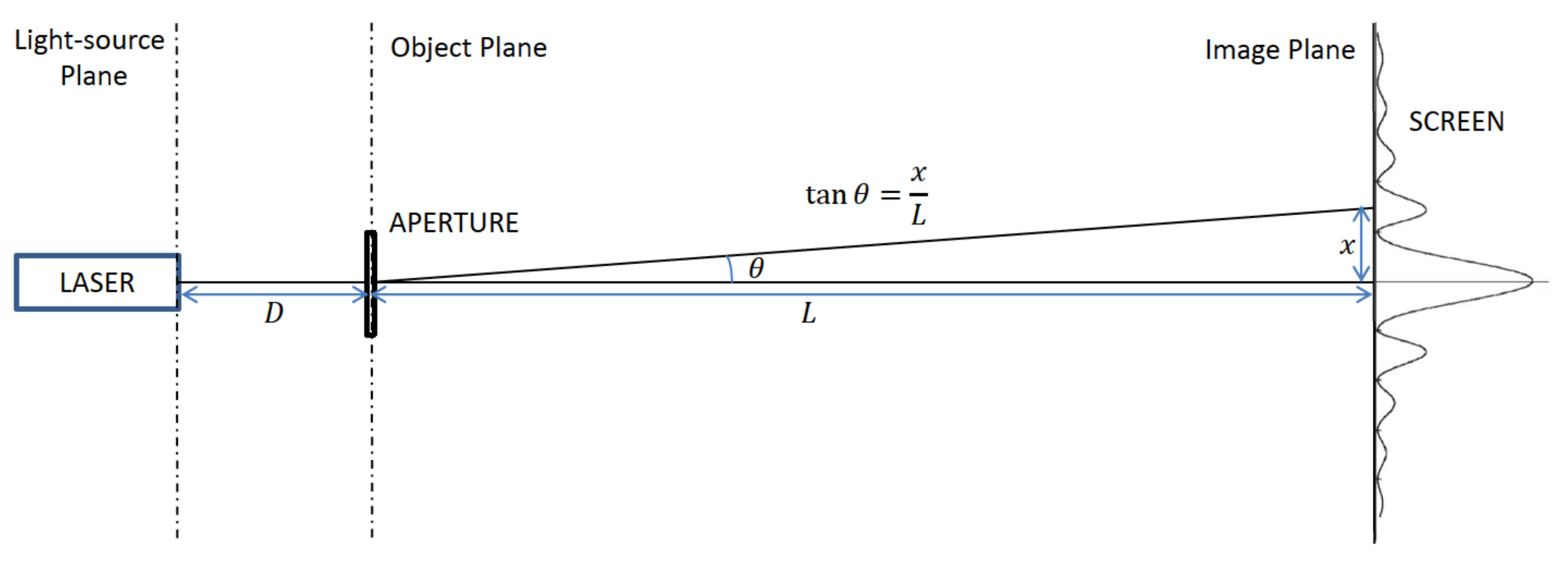
Figure 1 shows the experimental setup of a real, on-site diffraction experiment. The corresponding layout is depicted in
Figure 2. A laser beam leaving the light-source plane finds the aperture placed in the object plane. The light rays passing through the aperture interfere with each other, producing bright and dark fringes on a screen placed in the image plane.
If the image and object planes are quite apart from each other (i.e.,
L is large), the pattern observed is ruled by Fraunhofer (far-field) diffraction. On the contrary, if
L is not that large, the phenomenon belongs to Fresnel (near-field) diffraction regime. As a rule of thumb, an aperture of maximum width
d will produce Fraunhofer diffraction if:
being
in
Figure 2, and
the wavelength of the light beam. In the limit when
approaches to 0, the diffraction effect vanishes, and the image projected on the screen takes the form of the aperture, as predicted by geometric optics.
All the experiments simulated in OPTILAB belong to Fraunhofer, far-field diffraction regime. From
Figure 2, the angle
can be calculated as:
When
is very small (less than a few degrees), we can use the small-angle approximation:
Using the diffraction theory, one can predict the intensity profile and location of maxima (bright finges) and minima (dark fringes).
Table 1 summarizes those results for some classical apertures (e.g., single slit, double slit, circular aperture) [
12].
3. Description of the Tool
Former version of OPTILAB was developed in MATLAB [
13], to get advantage of the computing power provided by this environment. With the development of external math libraries in JAVA, we decided to move to this new platform. Main reason was that the executable files are ligther in size (less than 1 Mbyte each), and therefore, easier to download than the executables files produced by MATLAB runtime environment. On the other hand, MATLAB is a proprietary solution, while JAVA is a free, multiplatform solution (the same .JAR files can be executed on different operating systems).
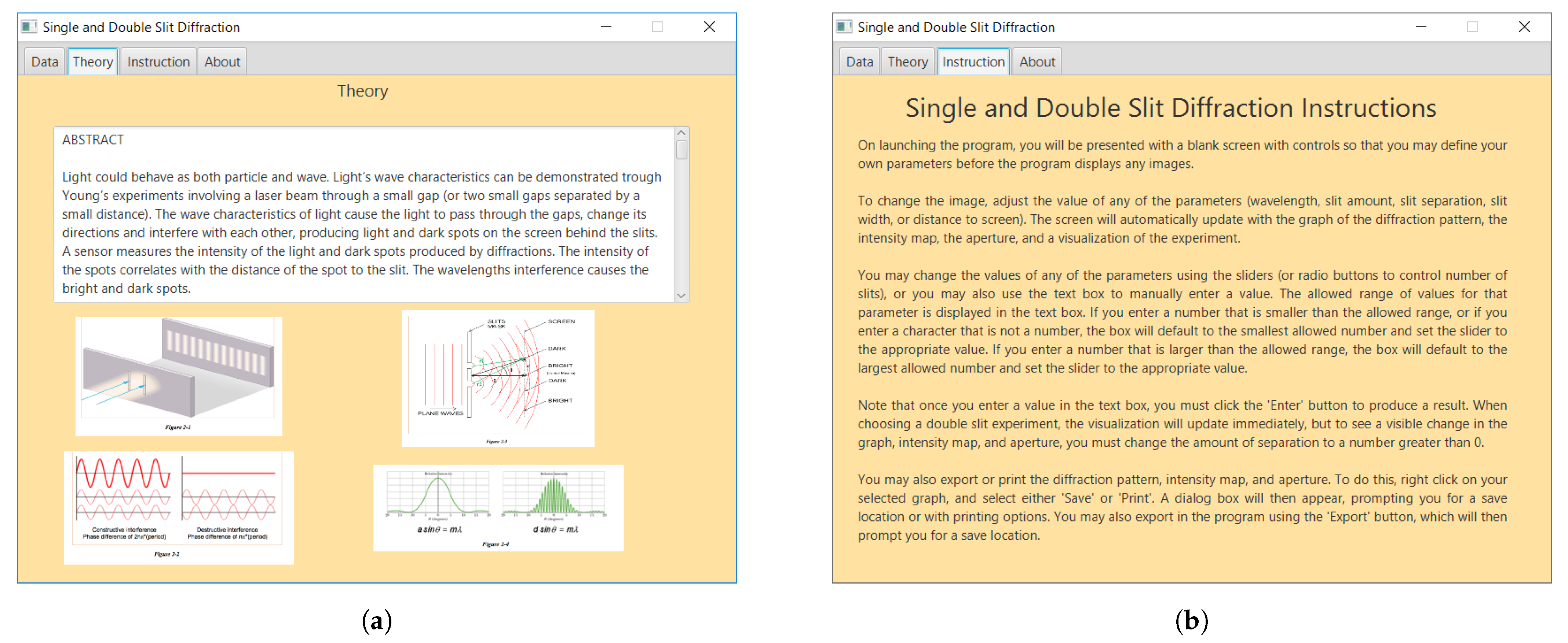
As part of the learning process, OPTILAB provides a short, theoretical background of the phenomenon to be studied, as depicted in
Figure 3a. With this on-line help, the student can refresh the physics concepts behind each experiment while doing the simulations. The software also includes instructions on how to run each simulation module, as shown in
Figure 3b.
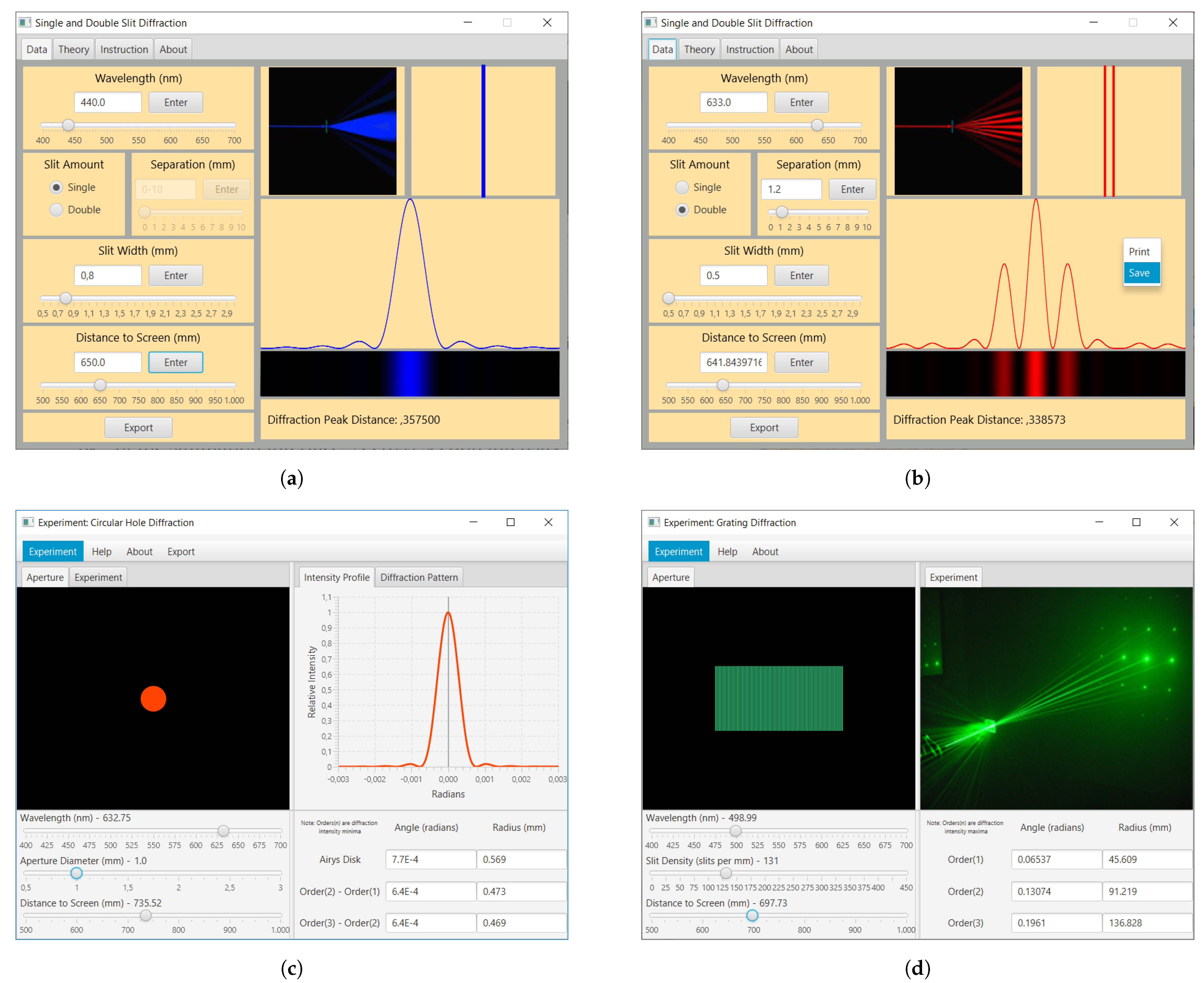
OPTILAB is made up of two executable (.JAR) files developed in JAVA (Standard Edition 8), one simulating single and double-slit diffraction experiments, and another one simulating diffractive grids and circular-apertures.
Figure 4a shows the simulation interface for calculating the diffraction pattern from vertical slits. The user can select the number of slits (single or double), the distance between slits (for double-slit), the slit width, the laser wavelength, and the distance from the slit to the output plane. Similar parameters are available for the rest of diffracting objects available. An schematic layout of the experiment is show in the upper-right corner of the interface. The simulated ray lights change in color according to the laser wavelength selected by the user. The diffraction pattern projected on the output plane is shown in the bottom-right frame of the simulation interface. A cross-section intensity profile of such diffraction pattern is also calculated, right on top of the corresponding diffraction pattern. The software allows the diffraction pattern to be sent to a printer, or stored as an image file on the PC for further processing. The simulation results can be also exported to a .TXT file for later comparison with the results obtained in a physical, on-site experiment.
Figure 4b describes the corresponding interface for diffraction experiments with circular-apertures. In this case, the diffraction pattern is the well-known Airy disk.
4. Virtual Lab Sessions Using OPTILAB
Due to COVID-19, academic managers of Polytechnic School at Carlos III University of Madrid (UC3M) decided to run 2 out of 4 lab sessions remotely on all engineering degrees during Fall 2020 and Spring 2021 terms, to reduce the number of simultaneous students in the lab facilities. OPTILAB was chosen by the Department of Physics at UC3M as the tool to build a virtual lab session replacing the on-site, interference and diffraction lab session in Physics III course (biomedical engineering).
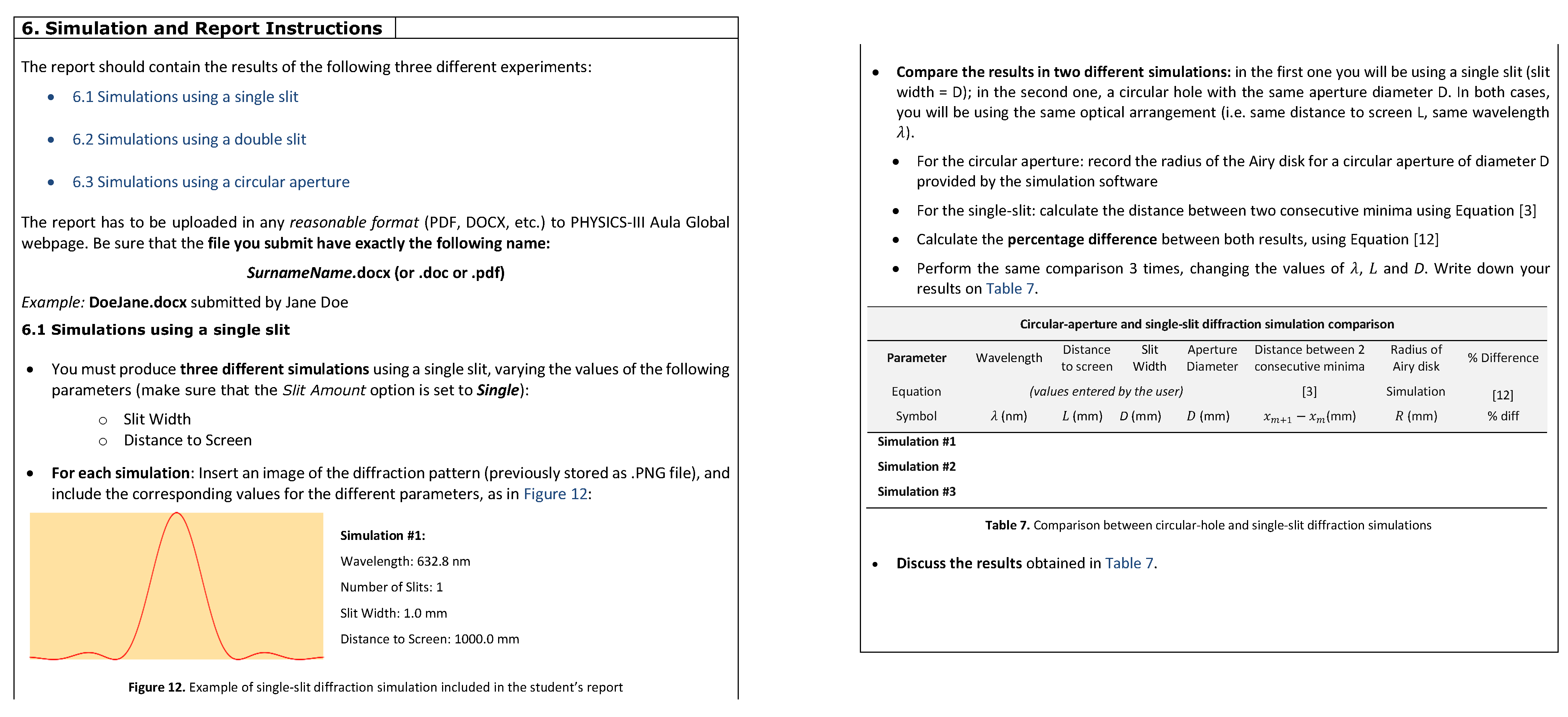
A 13-pages virtual-lab guide was developed to help the students to download, install and run the software. The virtual-lab guide also provides step-by-step instructions to perform the diffraction simulations and analysis which must be included by the students in their lab reports.
Figure 5 shows an excerpt of the simulation and reporting instructions included in the virtual-lab guide.
5. Results and Discussion
76 students registered for Physics III Course (biomedical engineering) during Fall 2020. They took the following lab sessions:
Session #1: Transformer (on-site)
Session #2 Magnetic Forces (on-site)
Session #3: Capacitors (virtual)
Session #4: Interference and Diffraction (virtual)
For Lab Session #3, an EXCEL tool was developed by other colleagues at the Department of Physics to simulate the behaviour of a parallel-plate capacitor under different conditions. Lab Session #4 was based in OPTILAB, as already explained.
Due to COVID, this was the first time students had to take lab sessions and deliver their lab reports individually (they usually did it in pairs). The 76 students were divided in 4 lab sections, with 2 different lab instructors; each lab instructor supervised and graded all the lab reports of 2 lab sections.
Table 2 summarizes the results obtained. The lab reports based on virtual lab sessions (#3) and (#4) obtained slightly higher scores than the on-site ones. Furthermore, the results obtained in Lab Report #4 (using OPTILAB) were the highest among all lab reports for both male (9.01 ± 0.87) and female (9.33 ± 0.43). Second-best result corresponds to Lab Report #3 (male: 8.64 ± 0.89; female: 9.19 ± 0.61), which was also a virtual lab session based on EXCEL simulations. According to these results, virtual lab sessions seem to be easier than on-site lab experiments. Some of the reasons for that can be already anticipated: students can perform the experiments at their own pace with no time pressure; there are no errors or risks associated with handling experimental equipment, etc. In any case, OPTILAB seems to be a good alternative to the physical lab session in exceptional situations like the current one imposed by COVID-19.
6. Conclusions
A software-based tool to study optical diffraction has been presented in this work. The tool, named OPTILAB, has been used during Fall 2020 semester in Physics III course (biomedical engineers) at UC3M, as a replacement to the on-site lab session. According to the results already presented, OPTILAB has proved to be a very useful tool in situations like the current COVID-19 pandemic, where partial/total lockdown prevented the access to physical lab facilities. Nevertheless, further analysis will be perform in future editions of the Physics III course mentioned above, to confirm whether there is a correlation in the grade results between on-site lab sessions and virtual lab sessions.
Funding
This research received no external funding.
Institutional Review Board Statement
Not applicable.
Informed Consent Statement
Not applicable.
Data Availability Statement
Not applicable.
Acknowledgments
The author would like to thank the students R. Bermudez, N. Vilimek, Y. Zghinou, B. Braun, C. Fox, and H. Wijiaji for all their dedication and efforts coding the Java version of OPTILAB software. The author would also like to thank the technical support obtained from the Unit of Teaching Educational Technology and Innovation (UTEID) at UC3M in the installation and testing of OPTILAB software at students’ ICT classrooms.
Conflicts of Interest
The author declares no conflict of interest.
Abbreviations
The following abbreviations are used in this manuscript:
| COVID | COronaVIrus Disease |
| ICT | Information and Communication Technologies |
| LR | Lab Report |
| UC3M | Carlos III University of Madrid |
| UTEID | Unit of Teaching Educational Technology and Innovation |
| VRL | Virtual Remote Laboratory |
References
- 30 Masters Programs in Photonics. Available online: https://www.masterstudies.com/Masters-Degree/Photonics/ (accessed on 15 September 2021).
- Davies, H. Competence-Based Curricula in the Context of Bologna and EU Higher Education Policy. Pharmacy 2017, 5, 17. [Google Scholar] [CrossRef] [PubMed] [Green Version]
- Frache, G.; Nistazakis, H.E.; Tombras, G.S. Reengineering engineering education: Developing a constructively aligned learning-by-doing pedagogical model for 21st century education. In Proceedings of the 2017 IEEE Global Engineering Education Conference (EDUCON), Athens, Greece, 25–28 April 2017; pp. 1119–1124. [Google Scholar]
- Gamo, J. Assessing a virtual laboratory in optics as a complement to on-site teaching. IEEE Trans. Educ. 2019, 62, 119–126. [Google Scholar] [CrossRef]
- Photonics Explorer. Available online: https://b-photonics.eu/en/photonics-explorer/ (accessed on 15 September 2021).
- Wild, G.; Swan, G.I. Optical fibre communications and sensing system experiments for undergraduate photonics laboratories. Proc. SPIE 2011, 8204, 82042Q. [Google Scholar]
- Mitchell-Waldrop, M. Education online: The virtual lab. Nature 2013, 499, 268–270. [Google Scholar] [CrossRef] [PubMed]
- Rodimin, V.; Ponomarev, M.; Kazieva, T.; Sharoglazova, V.; Krivoshin, E.; Kurochkin, Y. Modular Platform for Photonic Optical Experiments and Quantum Cryptography. In Proceedings of the 2019 International Siberian Conference on Control and Communications (SIBCON), Tomsk, Russia, 18–20 April 2019; pp. 1–3. [Google Scholar]
- Osten, W. Remote Laboratories for Optical Metrology: From the Lab to the Cloud. In Proceedings of the Latin America Optics and Photonics Conference, Cancun, Mexico, 16–21 November 2014; p. LTh2D.1. [Google Scholar]
- Mas, J.; Farre, A.; Cuadros, J.; Juvells, I.; Carnicer, A. Understanding Optical Trapping Phenomena: A Simulation for Undergraduates. IEEE Trans. Educ. 2011, 54, 133–140. [Google Scholar] [CrossRef] [Green Version]
- Chang, G.W.; Yeh, Z.M.; Chang, H.M.; Pan, S.Y. Teaching photonics laboratory using remote-control web technologies. IEEE Trans. Educ. 2005, 48, 642–651. [Google Scholar] [CrossRef]
- Hecht, E. Optics; Addison-Wesley: New York, NY, USA, 2002; Chapter 10. [Google Scholar]
- Gamo, J. A contribution to virtual experimentation in Optics. In Advanced Holography—Metrology and Imaging; Naydenova, I., Ed.; InTech: Rijeka, Croatia, 2011; pp. 357–374. [Google Scholar]
| Publisher’s Note: MDPI stays neutral with regard to jurisdictional claims in published maps and institutional affiliations. |
© 2021 by the author. Licensee MDPI, Basel, Switzerland. This article is an open access article distributed under the terms and conditions of the Creative Commons Attribution (CC BY) license (https://creativecommons.org/licenses/by/4.0/).


