Article

Design and Investigation of Mechanical Properties of Additively Manufactured Novel Coil-Shaped Wave Springs

by
Gul Jamil Shah
1,2,
Muhammad Rizwan ul Haq
2,3,* and
Jeng-Ywan Jeng
1,2
1
Department of Mechanical Engineering, National Taiwan University of Science and Technology, No. 43, Section 4, Keelung Road, Taipei 106, Taiwan
2
High-Speed 3D Printing Research Center, National Taiwan University of Science and Technology, No. 43, Section 4, Keelung Road, Taipei 106, Taiwan
3
Department of Design and Manufacturing Engineering (DME), School of Mechanical and Manufacturing Engineering (SMME), National University of Sciences and Technology (NUST), Islamabad 44000, Pakistan
*
Author to whom correspondence should be addressed.
Appl. Mech. 2025, 6(3), 61; https://doi.org/10.3390/applmech6030061
Submission received: 2 July 2025 / Revised: 8 August 2025 / Accepted: 11 August 2025 / Published: 14 August 2025

Abstract

Additive Manufacturing (AM) has revolutionized the production of intricate geometries tailored to customized functional mechanical properties, making it widely adopted across various industries, including aerospace, automotive, and biomedical sectors. However, the fabrication of mechanical springs has remained largely constrained by conventional manufacturing techniques, which limit their cross-sectional geometries to regular shapes, thereby restricting their mechanical performance and energy absorption capabilities. This limitation poses a significant challenge in applications where enhanced load-bearing capacity, energy absorption, and tailored stiffness characteristics are required. To address this issue, this study investigates the influence of coil shape on the mechanical properties of wave springs, specifically focusing on load-bearing capacity, energy absorption, stiffness, and compression behavior during cyclic loading and unloading. Nine contact-type wave springs with distinct coil shapes—square, rectangular, pentagonal, hexagonal, heptagonal, octagonal, quadro, circular (4 waves per coil), and circular (6 waves per coil)—were designed and fabricated using MultiJet Fusion (MJF) technology. Uni-axial compression testing was conducted over ten loading–unloading cycles to evaluate their mechanical performance and deformation characteristics. The results indicate that wave springs with square and rectangular coil shapes exhibit the highest energy absorption while maintaining the lowest stiffness and minimal energy loss during the first ten loading–unloading cycles. Furthermore, experimental findings were validated using finite element analysis (FEA) under identical boundary conditions, demonstrating close agreement with a deviation of only 2.3% compared with the experimental results. These results highlight AM’s potential for customizing wave springs with optimized mechanical performance.

1. Introduction

Additive Manufacturing (AM), commonly referred to as 3D printing, exhibits broad potential applications and promising capabilities in both industrial and academic fields, including automotive, biomedical, aerospace and engineering [1,2,3,4]. Compared to traditional manufacturing processes, AM technology has many distinguishing features, including the fabrication of complex geometries, which allow the researcher to fabricate and design various structures with improved mechanical properties, e.g., energy absorption capabilities [5,6,7,8]. AM techniques have been used to manufacture metallic honeycomb and truss structures for energy absorption applications as lightweight energy absorbers [9,10,11,12]. Similarly, the benefits of polymer-based cellular structures fabricated by 3D printing have also been extensively investigated [13,14].
Mechanical properties of auxetic-strut structures were investigated using AM, and the results indicate that the deformation pattern can be affected by changing the geometrical topology and, as a result, enabling the design of structures with various load-bearing capabilities, uniform stress distribution and energy absorption [15]. Additionally, it was found that auxetic-strut structures absorbed more energy and showed more compressive load than honeycomb structures. Other than these structures, various types of springs, including conical, helical, torsion, leaf, disc, tension, and wave springs, were better energy absorbers [16,17]. Research has been carried out to analyze helical springs with varying dimensions, fabricated using AM, to be used in shoe midsoles to withstand plantar pressure [18]. The result further revealed that springs with variable wire diameters and variable pitch profiles have greater stiffness relative to springs with constant parameters.
Wave spring is another form of spring that has a shorter length than a helical spring, but due to its unique design, it has the same mechanical properties [19]. Currently, wave springs, like other springs, are manufactured by traditional fabrication processes using customized machines with constant strip thickness and metal spring width, where variation in dimension and shape is almost impossible [20]. These springs have a variety of applications, including athletic shoes, valves, and other uses within the bio-medical industry [21,22,23]. The unlimited design freedom of AM allows researchers/engineers to design and manufacture wave springs with improved mechanical properties, i.e., stiffness, energy absorption, and load-bearing capacity. Haq et al. designed variable wave springs printed using Multi Jet Fusion (MJF) technology, and the results indicated that the mechanical properties can be changed significantly with geometric variations [24]. In another study, the same authors analyze the effects of strip thickness, wave height, number of waves and overlapping distance on mechanical properties. It was found that the stiffness is directly proportional to the cross-sectional area of the coil [25]. They also investigated the effect of wave height, the number of waves per coil, and the coil-to-coil overlapping on the mechanical properties and found a direct correlation between wave count and load-bearing capacity [7]. Likewise, a multifunctional shoe midsole was designed, incorporating a graded lattice structure and functionally gradient wave springs (FGWSs), which demonstrated that these polymeric base wave springs have enhanced energy absorption capabilities compared to metallic wave springs [26].
A literature review highlighted that traditional springs may not be utilized successfully for some specific applications when there are lateral and (or) vertical space limits due to an unintended increase in stiffness caused primarily when using numerous springs. The use of a non-circular spring can prevent these restrictions in lateral as well as vertical space. Choudhury et al. presented a methodology for designing non-circular coil shape springs and the process of obtaining the CAD models, followed by an FEA. The authors also investigated the advantages of the non-circular springs compared to cylindrical springs [27]. Despite recent advancements in wave spring geometry through AM, research has predominantly centered on cylindrical or circular coil designs, leaving the vast potential of non-circular wave springs largely untapped.
To bridge this gap, this study introduces the design and fabrication of novel non-circular contact wave springs, harnessing the unparalleled design flexibility of AM to enhance mechanical performance. By systematically investigating the influence of coil geometry on critical mechanical properties, such as energy absorption, stress–strain behavior, stiffness, compression characteristics, and load-bearing capacity, this research aims to unlock new possibilities for wave spring applications in space-constrained and performance-driven environments.

2. Materials and Methods

2.1. Designing of Non-Circular Contact Wave Spring

Non-circular contact wave springs were designed using SolidWorks software 2023 (Dassault Systems SolidWorks Corporation, Vélizy-Villacoublay, France) [28] using the same approach used by the authors in their previous studies [7,24,25,26]. In this study, circular, square, rectangular, pentagonal, hexagonal, heptagonal, octagonal, and quadro coils were designed. For uniform comparison and analysis, the height and weight of each design were kept constant.
Figure 1 illustrates the complete assembly and detailed features of each design, i.e., D1–D6, in which various non-circular shape coils were designed. The wave count in each coil in designs D1, D2, D7, and D8 is four, while the number of waves in D3–D6 and D9 is 5, 6, 7, 8, and 6, respectively. Wave height, strip width and number of coils in each assembly are 2, 5, and 4, respectively.
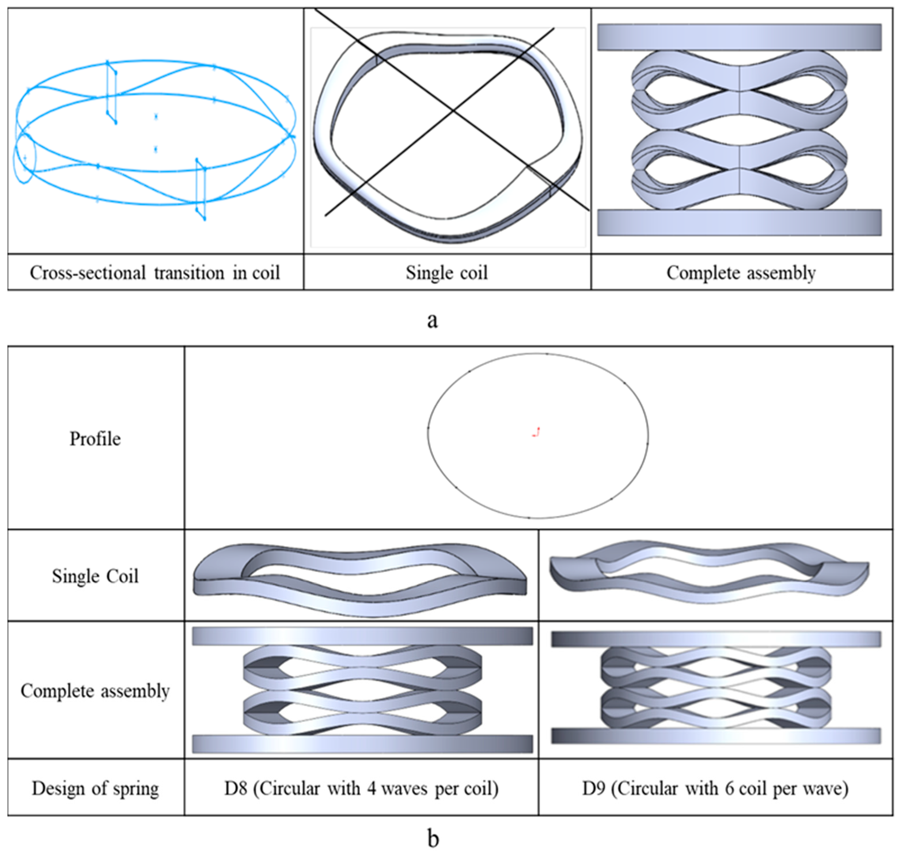
The previous study by the same authors found that the circular cross-sections have maximum energy absorption, but at the same time, more permanent deformation was observed in this design. In contrast, rectangular cross-sections have the highest load-bearing capacity, so Design D7 (Quadro design) incorporates a single coil with a cross-sectional transition from rectangular to round and vice versa, as shown in Figure 2a. For comparison of non-circular wave springs, two circular-shaped coil wave springs (D8 and D9) with 4 and 6 waves per coil were designed, as shown in Figure 2b.
Table 1 shows the complete names of designed wave springs along with the negligible variation in height.

2.2. Additive Manufacturing of Samples

Existing wave springs are cylindrical or circular in shape and manufactured by traditional manufacturing methods with customized machines, so any changes to the dimensions or geometric shape of the coil are extremely difficult. In this study, wave springs with variable shapes were successfully fabricated using MultiJet Fusion without the need for support structures, as the residual powder acts as support for these complex parts. Additionally, it offers a faster production rate compared to other AM processes, enabling rapid component fabrication with good quality, dimensional accuracy, and functionality [29].
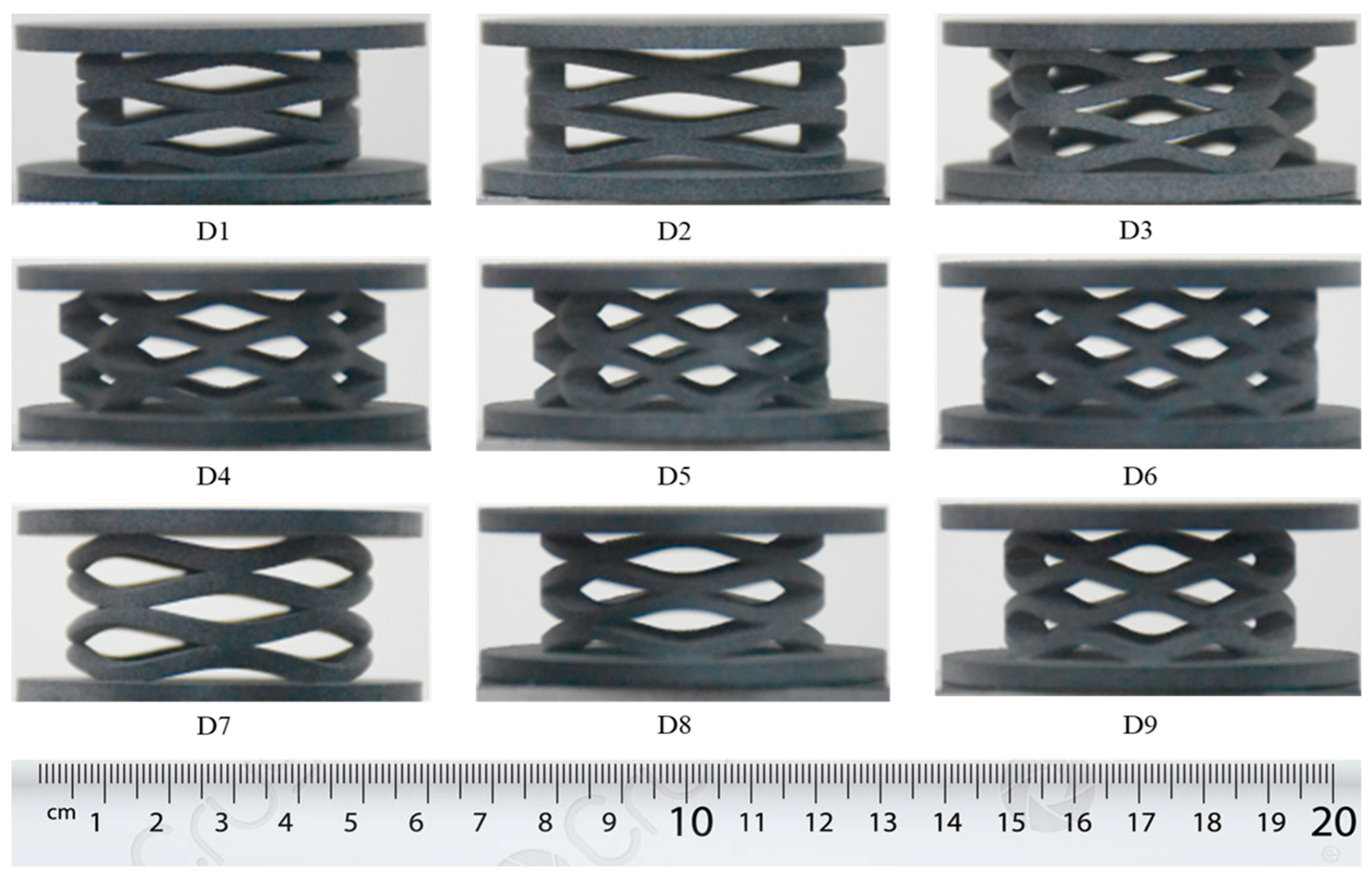
PA 12 (also known as Nylon 12) material was used to fabricate the samples for the presented study, which is a versatile, widely used plastic and is known for its exceptional mechanical properties, i.e., toughness, ability to flex without fracture, impact strength, and tensile strength [30]. This material has various industrial applications [31,32], having properties, i.e., poison ratio 0.33, density 1.01 g/cm3, and Young’s modulus 1250 MPa, which were also used in the FEA of the designs [32]. Three samples of each design were printed, as shown in Figure 3, by arranging the parts close to the center of the printing bed of the MJF printer, and the printing was performed in the vertical direction.
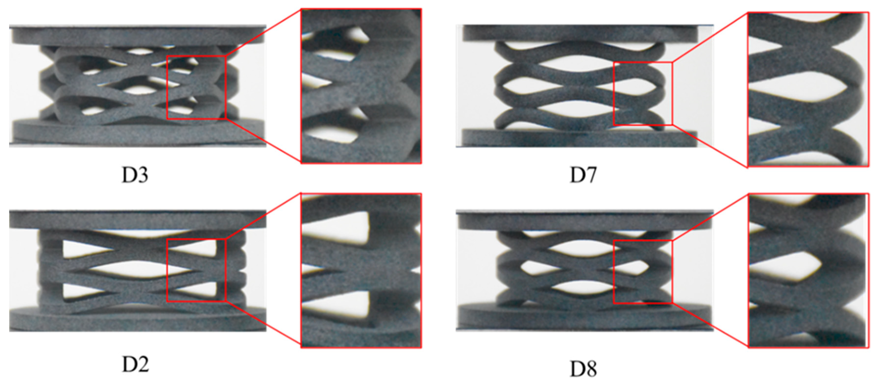
Visual inspection of the printed samples revealed no evidence of incomplete printing or voids and showed a minimum staircase effect. The coils were connected according to the CAD design. Additionally, the post-processing of the samples indicated that the residual powder was easily removed, revealing a clean and residue-free surface on each coil, as depicted in Figure 4.
In addition to visual inspection, the dimensions (e.g., height, width) and mass of three independent specimens per design (n = 3) were measured, and the difference between printed and designed samples is reported as mean ± standard deviation. A comparison of height and weight for designed and printed wave springs is tabulated in Table 2. The results revealed a maximum of 4% deviation in height and weight between printed and designed samples, which does not influence the results.

2.3. Uni-Axial Compression Testing (Loading–Unloading)

A MTS universal testing machine (MTS System Corporation, Eden Prairie, MN, USA) [33] with a crosshead speed of 300 mm/min was used for uni-axial compression testing (loading–unloading) of the three samples of each designed wave spring. The strain endpoint, a crucial parameter for the compression test, was determined for each design by calculating the ratio of the spring’s compressible distance to its total height. For safety and uniform accurate comparison, the samples were compressed up to 90% of their compressible distance till ten cycles of loading–unloading, as the wave springs achieve stability in terms of material setting and load-bearing capacity up to the 10th cycle [24,25]. Also, compression testing needs to be carried until the variation between two successive cycles of hysteresis loops reaches 3% [34], which is well achieved up to the 10th cycle in the present research. The strain endpoint, along with the compressible distance of each design, is tabulated in Table 3.

2.4. Simulation Framework

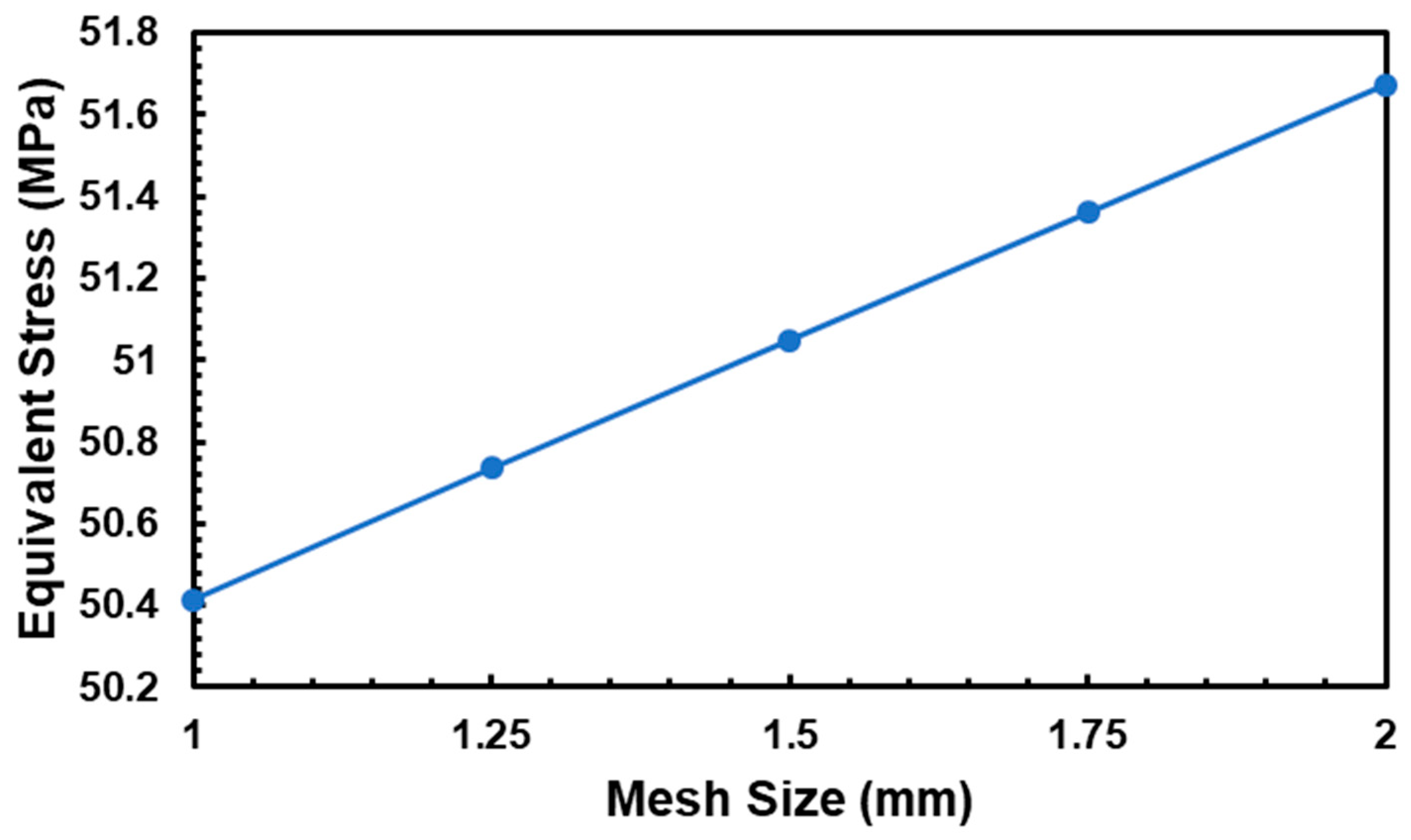
Experimental results were compared to FEA results performed using the same boundary conditions. ANSYS 19.2 Workbench [35] was used for the simulation of all designs. The boundary conditions were identical to experimental conditions, as the bottom plate was fixed and restricted all movements, while the top plate was subjected to displacement. The specified frictional contacts of coil–coil and coil–plate have a coefficient of friction of 0.2 [36]. The mesh sensitivity was checked using the convergence check, as illustrated in Figure 5 and Table 4. Since the variation in results is negligible and the mesh size was changed from 1 mm to 2 mm, a 2 mm mesh size was selected for each design. Although experimental testing was conducted within the elastic range, non-linear properties of the material were still provided in simulation to investigate the complete compression as well as the fracture behavior of each design. Also, the parts printed using MJF technology have nearly isotropic properties [37].

3. Results and Discussion

The average results of all three samples of each design were considered for load-bearing capacity, which were further investigated for the mechanical properties, i.e., stiffness, stress–strain behavior, energy loss/return, and energy absorption.

3.1. Compression Testing (Loading–Unloading)

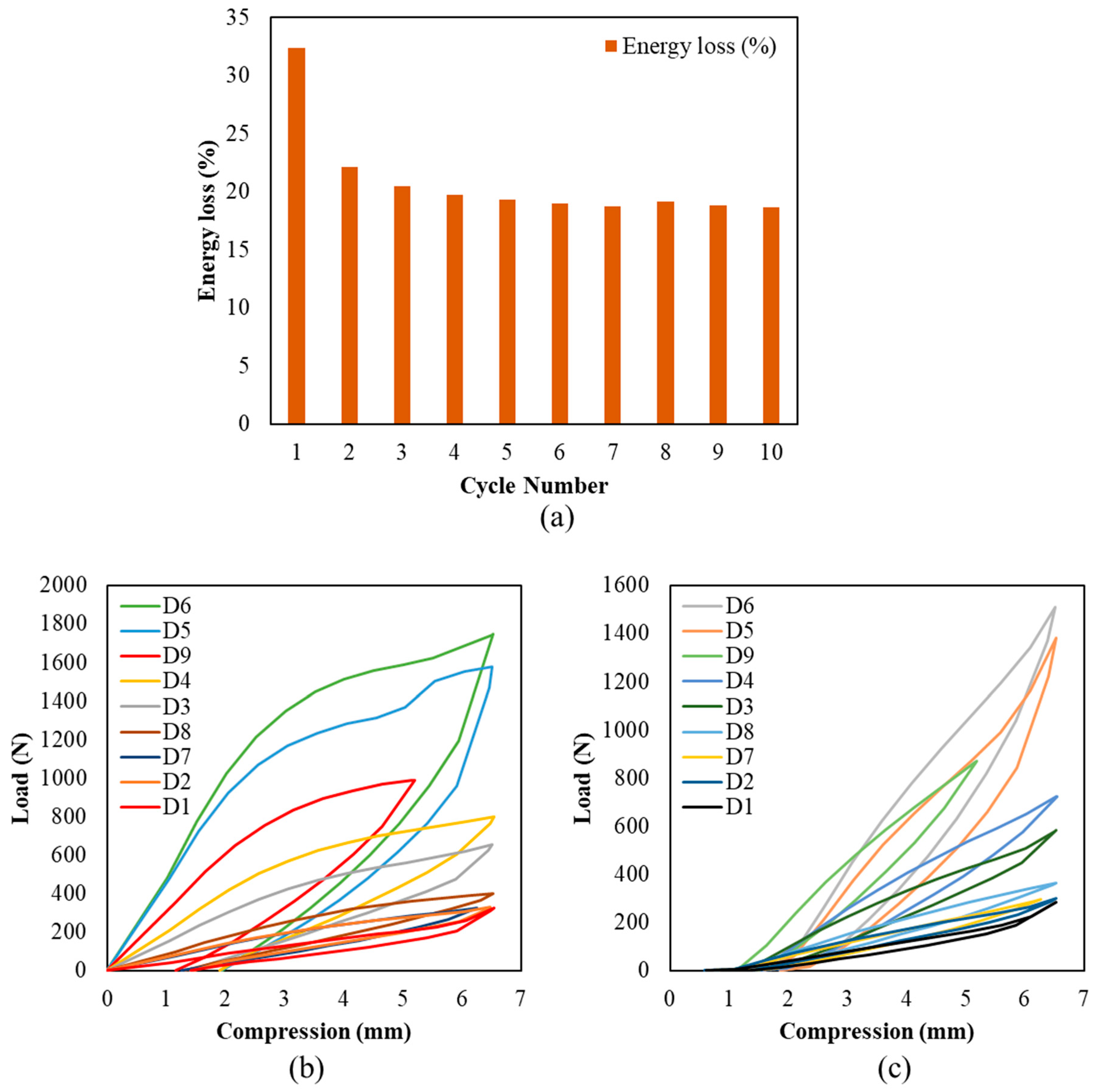
The results of mechanical testing revealed that the designed springs achieved stability in load-bearing capacity after the 8th cycle of loading–unloading, as shown in Figure 6a, with the first cycle requiring the most energy for material setting and micro-cavity deformation due to printing as well as layer adhesion, as subsequent cycles showed decreased energy requirement. Because of the variations in compressible distance, each spring exhibited a unique deformation behavior. Furthermore, printer settings and residual powder caused stiffness alteration in various sections of the same design, which also contributed to a significant change in properties throughout the first and second loading–unloading cycles.
Figure 6b,c compares the 1st and 10th cycles of each designed spring, which showed the deformation, i.e., the change in height observed, after completing 10 cycles for each design. This deformation was caused by microcavities, which caused resistance to coils returning to their initial position. The printing direction or build orientation affects the development of these micro-cavities or porosity as MJF-fabricated parts have the maximum porosity in the horizontal orientation [38].
During uni-axial compression testing, all the designs showed uniform compression; octagonal coil (D6) exhibited maximum and square design (D1) showed minimum load bearing capacity. Overall, the load-bearing capacity of D8 is more than D1 and D2 because, unlike circular design, the square and rectangular designs contained stress concentration points. Figure 7a presented a comparison of the D8, D1, D7, and D2 designs, with the D7 design performing better than the D1 and D2 designs but with a lower load-bearing capacity as compared to D8 due to cross-sectional changes inside the coil that produced stress concentration points.
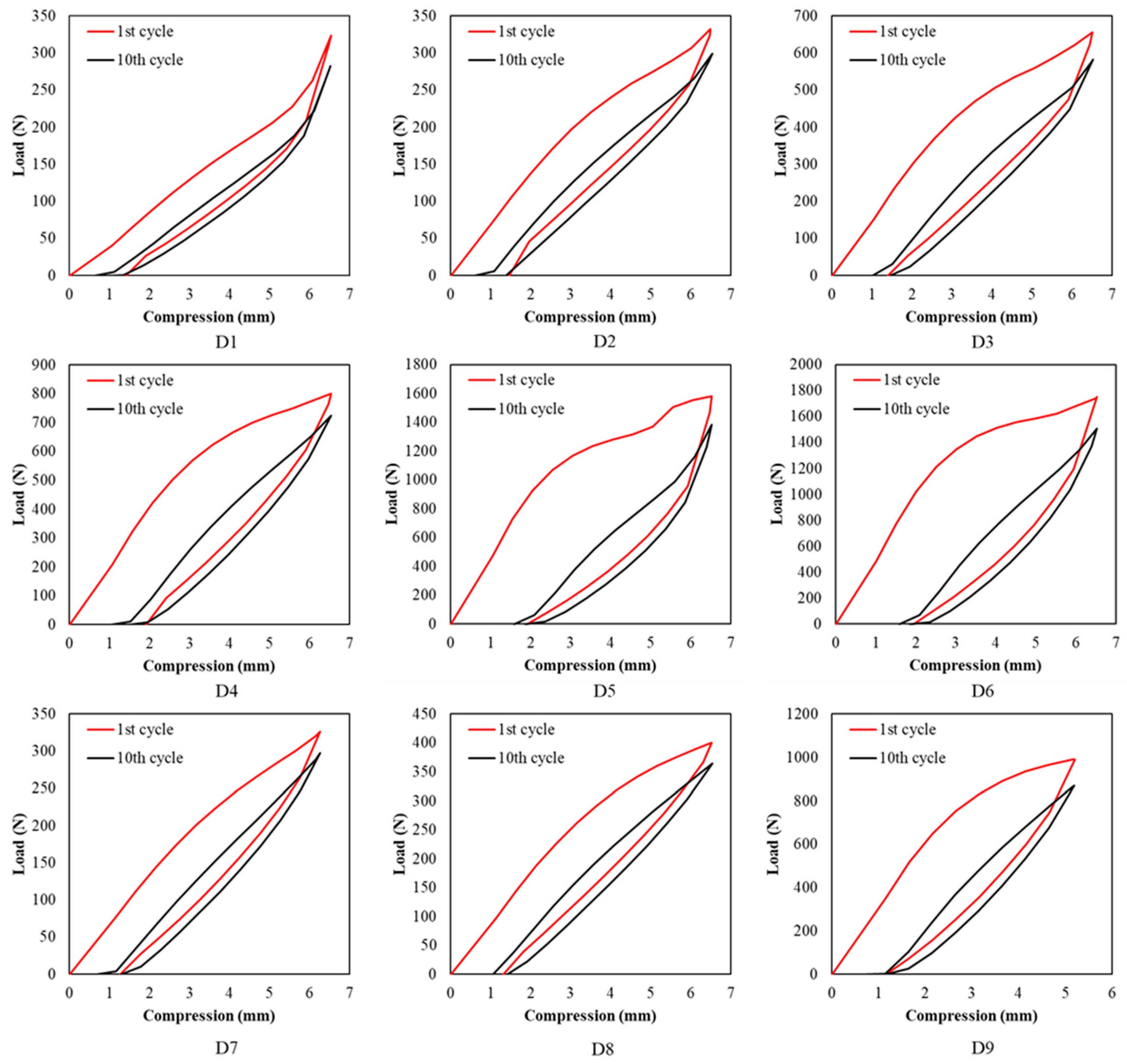
The octagonal design (D6) showed maximum load-bearing capacity, while the pentagonal design (D3) showed minimum load-bearing capacity, as shown in Figure 7b, i.e., from the pentagonal to the octagonal, the load-bearing capacity increased due to a change in the number of waves per coil. A comparison of the 1st and 10th cycles of loading–unloading is illustrated in Figure 8.
The comparison of load-bearing capacity showed that as the number of coils increases, the load-bearing capacity and energy absorption increase, but at the same time, there is more risk of plastic deformation due to highly stressed areas. Hence, the selection of waves per coil is strongly dependent on the application of the wave spring as per its prime objective.
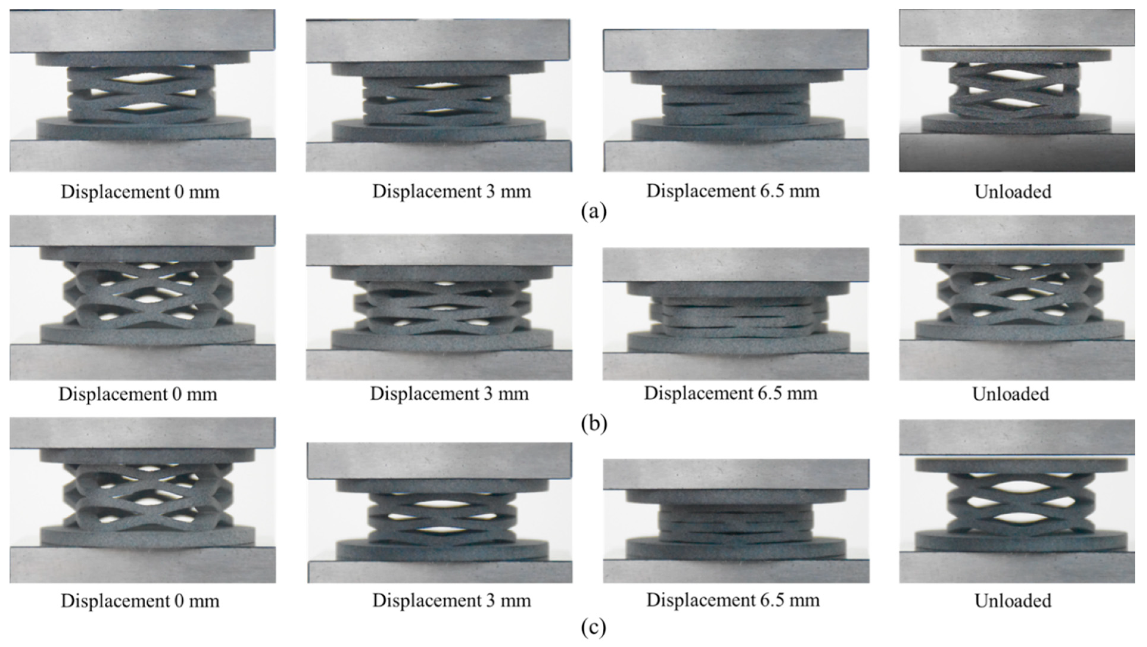
Overall, all the designs showed uniform compression with no cracks, and plastic deformation was observed after the 10th cycle of uni-axial compression. The experimental compression trends for D1, D3 and D8 are shown in Figure 9. These compression trends showed that the number of waves per coil has a significant effect on the uniform distribution of loads, as well as the stress concentration points.

3.2. Stiffness

The stiffness for each spring design was calculated using Equation (1)
S t i f f n e s s   o f   s p r i n g   ( k ) = F x
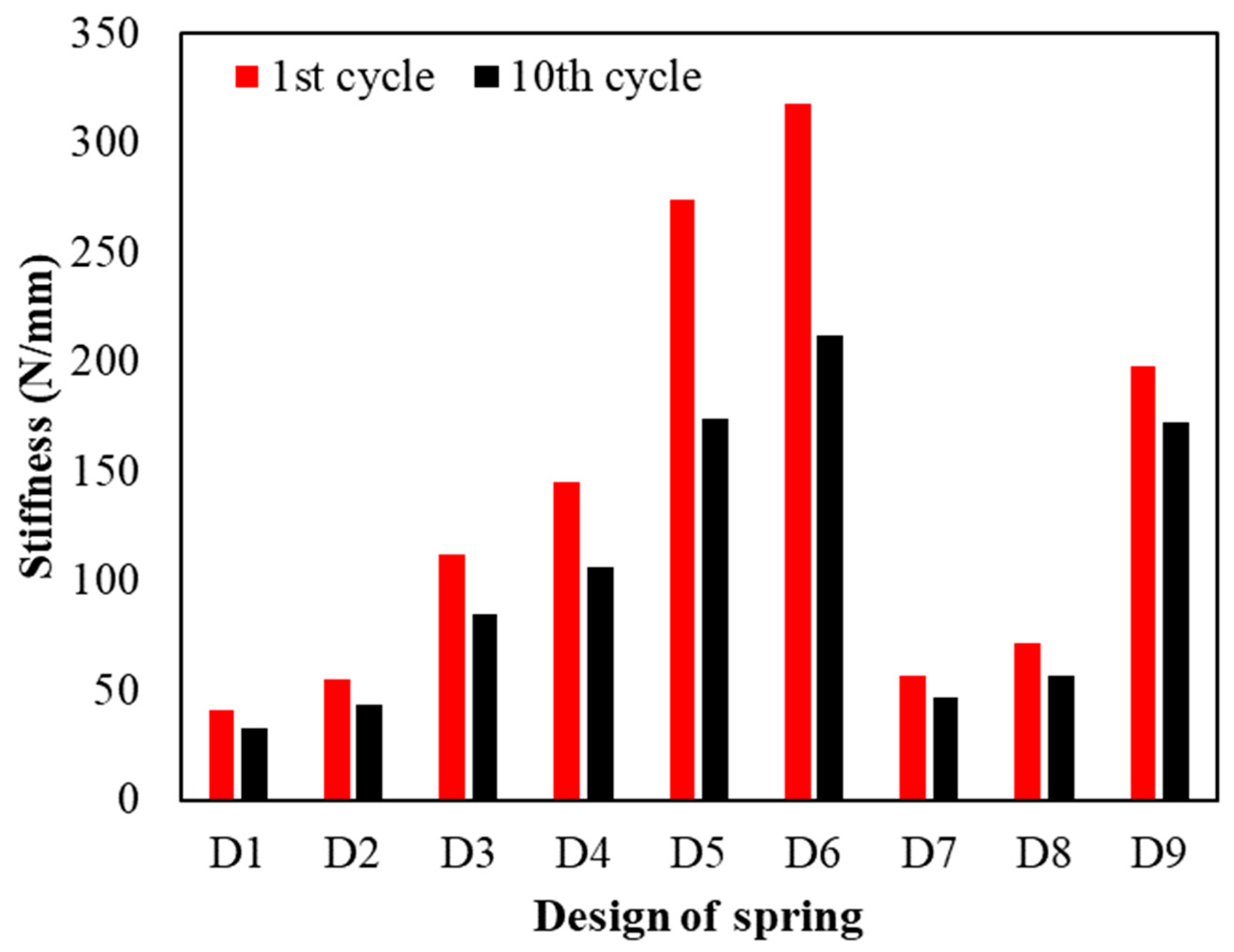
where “F” represents force or load applied while “x” denotes compression or displacement, which was considered constant for all designs to ensure uniform comparison, i.e., stiffness was calculated at a compression of 5 mm for each design. Figure 10 depicts a comparison of the stiffness of the first and tenth cycles of loading–unloading.
Overall, the stiffness showed a marked increase in the first cycle of loading because microcavities in additively manufactured components need greater force to deform, resulting in higher stiffness and vice versa. By the above comparison, it was found that the stiffness was much higher for heptagonal and octagonal wave springs than square or rectangular wave springs. It is worth noting that the significant increase in stiffness observed for Design D9, as compared to D8, is primarily due to the greater number of wave cycles in its geometry. The additional wave segments in D9 provide increased structural reinforcement and more uniform load distribution, which collectively enhance its resistance to deformation. Furthermore, D9 also exhibited superior stiffness retention over repeated loading, with a smaller percentage drop by the 10th cycle compared to D5 and D6. This suggests that the geometry of D9 contributes not only to higher initial stiffness but also to better durability under cyclic compression.

3.3. Energy Absorption

The energy absorption was evaluated by analyzing the energy input during the loading curve and energy loss during the unloading curve for each designed spring. The area under the loading curve (energy applied) was the energy that was absorbed by each spring, whereas the area under the unloading curve was the quantity of energy returned. Equation (2) was used to calculate energy loss.
E n e r g y   l o s s = E n e r g y   A p p l i e d E n e r g y   R e t u r n e d E n e r g y   A p p l i e d × 100
Calculations of energy loss were made for the first and tenth cycles of each design, as shown in Table 5.
D5 and D6 showed the maximum energy loss due to more stress concentration points, while D1, D2, D7 and D8 showed similar energy loss from the 1st to the 10th cycle, although the shape of the spring coil was different. The results showed that square and rectangular designs have uniform energy loss, but circular designs can be used without compromising energy absorption. Figure 11a and Figure 11b illustrated the energy returned for the 1st and 10th cycle and from the 1st to 10th cycle, respectively.

4. Comparison of Experimental and Simulation Results

The analysis of results revealed that the linear region results for each design were nearly identical, but the non-linear region results in significant variations. This variation is due to residual powder, geometric imperfections, surface thickness variability and buckling [39,40]. Additionally, the material’s isotropic properties were considered for the FEA, while the MJF process produced nearly isotropic parts; this difference may also contribute to the discrepancy between the results of the experiments and the FEA. The findings of the FEA for stress distribution showed that the design with varied shapes exhibited different stress concentration points in comparison to the circular design, which had stress that was distributed uniformly across the surface. Figure 12 presents a comparison of the experimental and simulated results for the loading–unloading curves of each design. The trend of the simulation and the experimental results is almost the same while the difference between these is negligible, i.e., almost 5 to 10%. This variation is due to the printing direction, the residual powder inside the coils, the boundary conditions and the difference in contact area due to the shape variation in the coils.
Figure 13a and Figure 13b compared the simulation and experimental compression trends of D1 and D7, respectively. From the compression trend, it was evident that the compression behavior is almost the same for experimental and simulation results. More uniformly distributed regions can be seen when the number of waves per coil was less, but as more waves were designed, the highly stressed regions were formed, which result in more plastic deformations.

5. Conclusions

This research shows the unlimited design freedom, diversity, and flexibility of AM by which non-circular wave springs were successfully designed and fabricated using MJF techniques. The analysis concluded the following results.
  • Square and rectangular wave springs lost 13% less energy than their heptagonal and octagonal counterparts. The octagonal shape has the maximum stiffness followed by the heptagonal and hexagonal shapes, while the square and rectangular designs showed the least rigidity.
  • Energy absorption and stiffness of square and rectangular designs were almost identical to those of circular designs.
  • The FEA and experiments showed similar behavior in compression, and the load-bearing graphs of each design are comparable. Non-linear regions of load-bearing graphs illustrated variations due to changes in thickness and the assumption that printed samples behaved isotopically during FEA.
  • Although the above presented study has given encouraging and new dimensions towards customized springs, it needs to be further investigated for fatigue as well as impact properties under different dynamic loadings. The number of waves in each coil needs to be a requirement of mechanical properties for specific applications as when the number of waves is increased, energy absorption is increased, but at the same time, the stress concentration points in each coil also increase, which is a prime limitation of this study. Similarly, more materials need to be used for manufacturing of these wave springs to investigate the mechanical properties as only one material was being used in the presented study.
These wave spring designs can be used in smart applications, e.g., smartwatches and robots. Wave springs outperform coil springs because they offer lower heights with the equivalent force, making them more suitable for space-saving and compact assemblies. This allows for an effective distribution of material, which lowers production costs.

Author Contributions

G.J.S.: data curation, formal analysis, methodology, software, writing original draft. M.R.u.H.: conceptualization, revisions of draft & editing, supervision, software, investigation, utilization of resources. J.-Y.J.: conceptualization, supervision, visualization, project administration, revisions of draft, utilization of resources. All authors have read and agreed to the published version of the manuscript.

Funding

This research received no external funding.

Institutional Review Board Statement

Not applicable.

Informed Consent Statement

Not applicable.

Data Availability Statement

The raw data supporting the conclusions of this article will be made available by the authors on request.

Acknowledgments

Dedicated to all the author, individuals, institutions, and organizations that supported in this research.

Conflicts of Interest

The authors declare no conflicts of interest.

References

  1. Shah, G.J.; Nazir, A.; Lin, S.-C.; Jeng, J.-Y.; Fu, R.Y.; Torun, H.; Feng, H.; Shah, G.J.; Nazir, A.; Lin, S.-C.; et al. Design for Additive Manufacturing and Investigation of Surface-Based Lattice Structures for Buckling Properties Using Experimental and Finite Element Methods. Materials 2022, 15, 4037. [Google Scholar] [CrossRef] [PubMed]
  2. Nazir, A.; Jeng, J.Y. Buckling Behavior of Additively Manufactured Cellular Columns: Experimental and Simulation Validation. Mater. Des. 2020, 186, 108349. [Google Scholar] [CrossRef]
  3. Dobos, J.; Hanon, M.M.; Keresztes, R.Z.; Oldal, I. Threshold Investigation of Shell Thickness for Enhanced Mechanical and Tribological Performance in 3D-Printed Curved Sandwich Structures. J. Braz. Soc. Mech. Sci. Eng. 2024, 46, 401. [Google Scholar] [CrossRef]
  4. Wu, Y.; Lu, Y.; Zhao, M.; Bosiakov, S.; Li, L. A Critical Review of Additive Manufacturing Techniques and Associated Biomaterials Used in Bone Tissue Engineering. Polymers 2022, 14, 2117. [Google Scholar] [CrossRef]
  5. Ciccone, F.; Bacciaglia, A.; Ceruti, A. Optimization with Artificial Intelligence in Additive Manufacturing: A Systematic Review. J. Braz. Soc. Mech. Sci. Eng. 2023, 45, 303. [Google Scholar] [CrossRef]
  6. Momeni, F.; Mehdi, M.; Hassani, N.S.; Liu, X.; Ni, J. A Review of 4D Printing. Mater. Des. 2017, 122, 42–79. [Google Scholar] [CrossRef]
  7. Haq, M.R.U.; Nazir, A.; Lin, S.-C.; Jeng, J.-Y. Investigating the Effect of Design Parameters on the Mechanical Performance of Contact Wave Springs Designed for Additive Manufacturing. 3D Print. Addit. Manuf. 2022, 11, 94–114. [Google Scholar] [CrossRef]
  8. Hassan, I.M.; Enab, T.A.; Fouda, N.; Eldesouky, I. Design, Fabrication, and Evaluation of Functionally Graded Triply Periodic Minimal Surface Structures Fabricated by 3D Printing. J. Braz. Soc. Mech. Sci. Eng. 2023, 45, 66. [Google Scholar] [CrossRef]
  9. Li, C.; Lei, H.; Liu, Y.; Zhang, X.; Xiong, J.; Zhou, H.; Fang, D. Crushing Behavior of Multi-Layer Metal Lattice Panel Fabricated by Selective Laser Melting. Int. J. Mech. Sci. 2018, 145, 389–399. [Google Scholar] [CrossRef]
  10. Baranowski, P.; Płatek, P.; Antolak-Dudka, A.; Sarzyński, M.; Kucewicz, M.; Durejko, T.; Małachowski, J.; Janiszewski, J.; Czujko, T. Deformation of Honeycomb Cellular Structures Manufactured with Laser Engineered Net Shaping (LENS) Technology under Quasi-Static Loading: Experimental Testing and Simulation. Addit. Manuf. 2019, 25, 307–316. [Google Scholar] [CrossRef]
  11. Al-Saedi, D.S.J.; Masood, S.H.; Faizan-Ur-Rab, M.; Alomarah, A.; Ponnusamy, P. Mechanical Properties and Energy Absorption Capability of Functionally Graded F2BCC Lattice Fabricated by SLM. Mater. Des. 2018, 144, 32–44. [Google Scholar] [CrossRef]
  12. Zhang, L.; Feih, S.; Daynes, S.; Chang, S.; Wang, M.Y.; Wei, J.; Lu, W.F. Energy Absorption Characteristics of Metallic Triply Periodic Minimal Surface Sheet Structures under Compressive Loading. Addit. Manuf. 2018, 23, 505–515. [Google Scholar] [CrossRef]
  13. Kumar, S.; Ubaid, J.; Abishera, R.; Schiffer, A.; Deshpande, V.S. Tunable Energy Absorption Characteristics of Architected Honeycombs Enabled via Additive Manufacturing. ACS Appl. Mater. Interfaces 2019, 11, 42549–42560. [Google Scholar] [CrossRef]
  14. McGregor, D.J.; Tawfick, S.; King, W.P. Mechanical Properties of Hexagonal Lattice Structures Fabricated Using Continuous Liquid Interface Production Additive Manufacturing. Addit. Manuf. 2019, 25, 10–18. [Google Scholar] [CrossRef]
  15. Ingrole, A.; Hao, A.; Liang, R. Design and Modeling of Auxetic and Hybrid Honeycomb Structures for In-Plane Property Enhancement. Mater. Des. 2017, 117, 72–83. [Google Scholar] [CrossRef]
  16. Types of Springs and Their Uses-Grainger KnowHow. Available online: https://www.grainger.com/know-how/equipment/kh-types-springs?utm_source (accessed on 2 April 2025).
  17. Types of Springs and Their Applications-SMLease Design. Available online: https://www.smlease.com/entries/mechanism/types-of-springs-and-their-applications/ (accessed on 2 April 2025).
  18. Ali, M.; Nazir, A.; Jeng, J.Y. Mechanical Performance of Additive Manufactured Shoe Midsole Designed Using Variable-Dimension Helical Springs. Int. J. Adv. Manuf. Technol. 2020, 111, 3273–3292. [Google Scholar] [CrossRef]
  19. Wave Spring vs. Coil Spring|Smalley. Available online: https://www.smalley.com/blog/wave-spring-vs-coil-spring?utm_source (accessed on 10 April 2025).
  20. Smalley Wave Springs|Smalley. Available online: https://www.smalley.com/wave-springs (accessed on 9 March 2023).
  21. Fonte, M. Wave Spring for a Spinal Implant No. US9039766B1. Available online: https://patents.google.com/patent/US9039766B1/en (accessed on 10 March 2025).
  22. Le Vert, F.; Krafsur, D. Spring Cushioned Shoe-Google Patents. No. US20050126039A1. Available online: https://patents.google.com/patent/US20080209762A1/en (accessed on 15 April 2025).
  23. Custom Wave Spring Manufacturer|Teamco. Available online: https://www.teamco.com.tw/en/product/wave-springs.html (accessed on 2 March 2025).
  24. Haq, M.R.U.; Nazir, A.; Jeng, J.Y. Design for Additive Manufacturing of Variable Dimension Wave Springs Analyzed Using Experimental and Finite Element Methods. Addit. Manuf. 2021, 44, 102032. [Google Scholar] [CrossRef]
  25. Erfanian-Naziftoosi, H.R.; Shams, S.S.; Elhajjar, R. Composite Wave Springs: Theory and Design. Mater. Des. 2016, 95, 48–53. [Google Scholar] [CrossRef]
  26. Dragoni, E. A Contribution to Wave Spring Design. J. Strain Anal. Eng. Des. 2007, 23, 145–153. [Google Scholar] [CrossRef]
  27. Chaudhury, A.N.; Datta, D. Analysis of Prismatic Springs of Non-Circular Coil Shape and Non-Prismatic Springs of Circular Coil Shape by Analytical and Finite Element Methods. J. Comput. Des. Eng. 2017, 4, 178–191. [Google Scholar] [CrossRef]
  28. SOLIDWORKS. Available online: https://www.solidworks.com (accessed on 9 March 2023).
  29. HP 3D Jet Fusion 4200-Commercial & Industrial 3D Printer|HP® Official Site|HP® Official Site. Available online: https://www.hp.com/us-en/printers/3d-printers/products/multi-jet-fusion-4200.html (accessed on 20 March 2025).
  30. Cai, C.; Tey, W.S.; Chen, J.; Zhu, W.; Liu, X.; Liu, T.; Zhao, L.; Zhou, K. Comparative Study on 3D Printing of Polyamide 12 by Selective Laser Sintering and Multi Jet Fusion. J. Mater. Process. Technol. 2021, 288, 116882. [Google Scholar] [CrossRef]
  31. Polyamide 12 (PA 12)-3D Printing with Nylon Plastic|Fast Radius. Available online: https://www.fastradius.com/resources/polyamide-12/ (accessed on 9 March 2023).
  32. Introduction the Characteristics and Application of Nylon 12 (Polyamide 12/PA 12) Material|Over 40 Years of World-Class Wire & Cable Management Products Manufacturing|HUA WEI. Available online: https://www.hwlok.com/en/technical-info/Material-PA12.html (accessed on 30 January 2025).
  33. Materials Test Systems. Available online: https://www.mts.com/en/applications/materials/test-type/compression (accessed on 10 February 2025).
  34. Sun, P.C.; Wei, H.W.; Chen, C.H.; Wu, C.H.; Kao, H.C.; Cheng, C.K. Effects of Varying Material Properties on the Load Deformation Characteristics of Heel Cushions. Med. Eng. Phys. 2008, 30, 687–692. [Google Scholar] [CrossRef]
  35. Ansys|Engineering Simulation Software. Available online: https://www.ansys.com/ (accessed on 10 April 2025).
  36. Bai, J.; Song, J.; Wei, J. Tribological and Mechanical Properties of MoS2 Enhanced Polyamide 12 for Selective Laser Sintering. J. Mater. Process. Technol. 2019, 264, 382–388. [Google Scholar] [CrossRef]
  37. Habib, F.N.; Iovenitti, P.; Masood, S.H.; Nikzad, M. Fabrication of Polymeric Lattice Structures for Optimum Energy Absorption Using Multi Jet Fusion Technology. Mater. Des. 2018, 155, 86–98. [Google Scholar] [CrossRef]
  38. Lee, K.P.M.; Pandelidi, C.; Kajtaz, M. Build Orientation Effects on Mechanical Properties and Porosity of Polyamide-11 Fabricated via Multi Jet Fusion. Addit. Manuf. 2020, 36, 101533. [Google Scholar] [CrossRef]
  39. Sui, Q.; Fan, H.; Lai, C. Failure Analysis of 1D Lattice Truss Composite Structure in Uniaxial Compression. Compos. Sci. Technol. 2015, 118, 207–216. [Google Scholar] [CrossRef]
  40. Schenk, C.A.; Schuëller, G.I. Buckling Analysis of Cylindrical Shells with Cutouts Including Random Boundary and Geometric Imperfections. Comput. Methods Appl. Mech. Eng. 2007, 196, 3424–3434. [Google Scholar] [CrossRef]
Figure 1. Design overview of different coils along with feature details for each design.
Applmech 06 00061 g001
Figure 2. (a) D7 feature details; (b) D8 and D9 design summary along with complete assembly.
Applmech 06 00061 g002
Figure 3. Printed samples showed good quality of surface finish, dimensions and details of each designed feature.
Applmech 06 00061 g003
Figure 4. The printed samples demonstrated successful powder removal and good surface finish.
Applmech 06 00061 g004
Figure 5. Convergence check for mesh sensitivity.
Applmech 06 00061 g005
Figure 6. (a) Energy loss pattern in D1 over 10 cycles is representative of all designs. Load-bearing capacity comparison for (b) first cycle and (c) tenth cycle.
Applmech 06 00061 g006
Figure 7. Comparison of load-bearing capacity reveals that (a) D7 design has a greater load-bearing capacity than D1 and D2 but a lower load-bearing capacity than D8; (b) D6 has greater capacity compared to D3, D4 and D5.
Applmech 06 00061 g007
Figure 8. Load vs. compression analysis for each designed wave spring’s 1st and 10th cycles. All of this is based on experimental analysis.
Applmech 06 00061 g008
Figure 9. (a) D1, (b) D3, and (c) D8 all exhibited uniform compression in their compression trend.
Applmech 06 00061 g009
Figure 10. The comparison of each design’s stiffness after the 1st and 10th cycles of loading–unloading was notable.
Applmech 06 00061 g010
Figure 11. Each design returned energy. (a) The 1st and 10th cycles. (b) The amount of energy returned for each design from the 1st to the 10th cycle.
Applmech 06 00061 g011
Figure 12. Comparison of experimental and simulation results.
Applmech 06 00061 g012
Figure 13. Simulation and experimental compression trends of (a) D1 and (b) D7 are compared. The simulation and experimental compression trends show uniformity.
Applmech 06 00061 g013
Table 1. The complete nomenclature of designed wave springs.
DesignName of Coil ShapeHeight (mm)Weight (g)
D1Square21.213.87
D2Rectangular21.614.36
D3Pentagonal21.214.60
D4Hexagonal21.214.67
D5Heptagonal21.214.37
D6Octagonal21.214.82
D7Quadro24.413.36
D8Circular (4 wave per coil)21.214.22
D9Circular (6 wave per coil)21.714.25
Table 2. Designed vs. printed dimensions and mass (mean ± SD, n = 3), showing negligible variation.
DesignCAD
Height (mm)
Printed
Height (mm)
Variation (%)CAD
Weight
(g)
Printed
Weight
(g)
Variation (%)
D121.221.50 ± 0.031.4%13.8714.07 ± 0.051.4%
D221.621.80 ± 0.030.9%14.3614.55 ± 0.051.3%
D321.221.60 ± 0.031.9%14.6014.94 ± 0.052.3%
D421.221.50 ± 0.031.4%14.6714.72 ± 0.050.3%
D521.221.70 ± 0.032.4%14.3714.49 ± 0.050.8%
D621.221.70 ± 0.032.4%14.8215.36 ± 0.053.6%
D724.425.10 ± 0.032.9%13.3613.66 ± 0.052.2%
D821.221.50 ± 0.031.4%14.2214.51 ± 0.052.0%
D921.722.10 ± 0.031.8%14.2514.60 ± 0.052.5%
Table 3. Compression test results for each design (mean ± SD, n = 3), showing minimal variation.
DesignTotal Height
(mm)
Compressible Height (mm)90% of Compressible Height (mm)Strain End Point
D121.50 ± 0.037.20 ± 0.036.50 ± 0.030.30
D221.80 ± 0.037.20 ± 0.036.50 ± 0.030.30
D321.60 ± 0.037.20 ± 0.036.50 ± 0.030.30
D421.50 ± 0.037.20 ± 0.036.50 ± 0.030.30
D521.70 ± 0.037.20 ± 0.036.50 ± 0.030.30
D621.70 ± 0.037.20 ± 0.036.50 ± 0.030.30
D725.10 ± 0.037.00 ± 0.036.30 ± 0.030.25
D821.50 ± 0.037.20 ± 0.036.50 ± 0.030.30
D922.10 ± 0.035.70 ± 0.035.20 ± 0.030.23
Table 4. Negligible effect observed with varying mesh size.
Mesh Size (mm)Equivalent Stress (MPa)Change %NodesElements
1.50.413 57,57333,360
2.50.7359.25120,85174,434
3.51.0486.46184,438115,809
4.51.3615.31248,136157,283
5.52.5842.19311,123198,057
Table 5. Loss of energy in all designs during cycle 1 and cycle 10, as well as loss of energy from cycle 1 to cycle 10.
DesignEnergy
1st Cycle10th Cycle(Cycle 1st–10th)
Applied (mm2)Released (mm2)Loss
(%)
Applied (mm2)Released (mm2)Loss
(%)
Loss (%)
D10.23−0.15350.16−0.131817
D20.31−0.19390.22−0.172117
D30.66−0.35470.41−0.312521
D40.87−0.41520.51−0.362824
D51.75−0.61650.79−0.513530
D61.99−0.74630.94−0.623429
D70.25−0.15400.17−0.132317
D80.41−0.25400.28−0.212217
D90.84−0.40520.47−0.342724
Disclaimer/Publisher’s Note: The statements, opinions and data contained in all publications are solely those of the individual author(s) and contributor(s) and not of MDPI and/or the editor(s). MDPI and/or the editor(s) disclaim responsibility for any injury to people or property resulting from any ideas, methods, instructions or products referred to in the content.