Article

A Fast Analytical Method for Elastic–Plastic Analysis of Threaded Connections

by
Carlo Brutti
*,
Corrado Groth
and
Marco Evangelos Biancolini
Department of Enterprise Engineering, University of Rome Tor Vergata, Via del Politecnico, 1, 00133 Rome, Italy
*
Author to whom correspondence should be addressed.
Appl. Mech. 2025, 6(2), 42; https://doi.org/10.3390/applmech6020042
Submission received: 18 April 2025 / Revised: 20 May 2025 / Accepted: 29 May 2025 / Published: 6 June 2025

Abstract

Threaded connections are fundamental in engineering structures, yet their elastic–plastic behavior under load remains challenging to model analytically. The yield limit can be reached under relatively small external loads, and elastic–plastic behavior has predominantly been studied using finite element models. While these models are highly valuable, they are often restricted to specific cases. This paper presents a novel extension of Maduschka’s classical method, offering a fast and efficient analytical approach to evaluate the behavior of screw–nut–washer assemblies. The method tracks plastic strain progression from initial yielding to full yield conditions and is validated against high-fidelity axisymmetric and 3D finite element analyses (FEAs) across a range of thread dimensions (M16–M36). Results demonstrate strong agreement with FEA benchmarks while achieving significant computational speedups, making the method suitable for iterative and large-scale analyses. In addition, the comparison with results available in the literature further supports the reliability of the proposed method. Its robustness to variations in geometry, friction, and thread count positions it as a foundation for reduced-order models, ready for integration into complex finite element frameworks commonly used in structural health monitoring and digital twin technologies.

Graphical Abstract

1. Introduction

Screwed connections are widespread; they are used in all engineering applications because they have many advantages, including availability, standardization, and simple assembly and disassembly. The structural behavior of screw threads has been studied since the beginning of the twentieth century, and the scientific and technical bibliography is extensive, as reported in many review papers [1,2,3].
In a threaded joint design, it is necessary to consider the non-uniform load distribution among the engaged threads; the most popular theoretical approaches are those of Maduschka [4], Sopwith [5], and Yamamoto [6]. In the last decades, the same problem has predominantly been solved by using finite element (FE) models [7]. Another approach is that of Zhang et al. [8], which addressed the problem of a compression connection and validated the results using a finite element method. The methods of Sopwith, Yamamoto, and Zhang are based on the integration of differential equations defined along the helix of the threads. In contrast, Maduschka’s method used in his paper of 1936 for a squared threaded connection, a succession of axisymmetric collars attached to the body of the screw and the nut as shown in Figure 1, extracted from the original paper where three cases of engagement are shown. The assembly shown regards squared threads, but in the following of the original paper, also the triangular threads are examined. The figure has been corrected and revised by us to improve the quality.
For all analytical approaches, the compliance of the threads plays a crucial role. The experimental verification of the reliability of these theoretical models has been checked with different methods [9,10,11,12] and generally has shown good agreement.
Relating to the strength of the connection, the critical points are located at the root of the first engaged thread and under the bolt head. After the classic papers by Heywood [13] and Kenny and Patterson [14], several works have been devoted to the modification of the thread geometry to reduce stress concentrations [15,16]. For example, Calì et al. [17] used mesh morphing to find an optimal geometry modifying the standard proportion. Other contributions have studied the effects of bolt thread geometry [18], and the modification of the washer [19]. In addition, all of these topics have been extensively treated for the case of threaded abutments in implant dentistry [20] using an FE model [21].
Near the root of the thread, the stress state overcomes the yield limit for moderate external loads. Due to this state of strain, the load distribution changes significantly. Examining the extended bibliography on this specific topic, few papers take theoretical approaches; the main method of investigation of the elastic–plastic behavior is numerical, using FE models. Chen and Williams [22] proposed a simplified method to study the threaded connection in pipes. Wang and Marshek [23] adapted a previously developed elastic approach to the case of elastic–perfectly plastic strain. Fukuoka and Takaki [24] investigated the tightening process using FE modeling. Sun and Liao [25] shown that the axial load and stress distributions obtained from the axisymmetric FE model agree with the results of 3D FE in both elastic and plastic states with the same mesh density. Sawa et al. [26] focused their attention on the load of starting plastic strain and introduced the effects of the first incomplete thread of the nut. Zhang et al. [27] modified the Yamamoto equation, which refers to the elastic behavior, to include the plastic strains based on the numerical results. Finally, Redondo and Mehmanparast [28] studied the case of bolted connections in wind turbines, considering the tightening process and focusing their attention on the stress distribution and the plastic strain. More recently, Chen et al. [29] studied an analysis method for stress distribution along the engaged threads considering plastic deformation. Starting from an analytical model within the elastic range [30], they introduced a parametric nonlinear finite element model to represent the plastic behavior. Several interesting experimental results are in the references [31,32,33,34]. In particular, in [34], the effects of the actual machining conditions have been studied showing that the resulting stress distribution is discontinuous and not uniform.
As shown by this synthetic reference discussion, the elastic–plastic behavior of the screw–nut–washer (SNW) assembly has been analyzed more frequently by FE models than theoretically; however, these contributions give interesting results only for particular applications. In contrast, very few studies solve this problem in a general way with a theoretical approach suitable for many cases. When stressed beyond the elastic limit, the behavior of bolt and nut assemblies is very important for evaluating the response of several types of structures under operational or emergency loads. In this paper, we improved Maduschka’s approach to consider elastic–perfectly plastic behavior. This method was chosen because the engaged threads can be treated as collars connected only through the cross-section of the screw or the nut. In other words, this approach is intrinsically discrete and includes straightforwardly the non-linear behavior. When the strains overcome the elastic limit, the compliance of the threads and of the screw/nut bodies changes along the joint. The first step of our investigation was to consider how to modify Maduschka’s equations to remove some simplifications, which was useful and adequate for the elastic case but was not reliable when the yield occurs. Then, the plastic behavior of the thread was investigated, defining the load of the initiation of the plastic strain and the final load at which the entire thread root section is in the plastic regime. The peak stress at the root of the thread was used to determine the initial yield. The stress at the center of this section, where the effect of the bending and concentration factors is null, was used to define the load when the entire thread is in the plastic state. Combining these elements, a step-by-step procedure for determining the elastic–plastic load distribution was stated. This theoretical method was checked successfully through an extended numerical investigation using an axisymmetric and three-dimensional FE model considering ISO threads from M16 through M36. It showed good agreement between the numerical and theoretical results. In addition, due to the relatively small scattering of the results in the size range investigated, a simplified procedure was obtained to obtain the yield-starting load (YS) and the yield-ending load (YE) directly. This last result appears very useful for defining a reduced order model (ROM) of a bolt and nut in a more complex FE model, such as those used in structural monitoring by digital twins [35].

2. Theoretical Approach

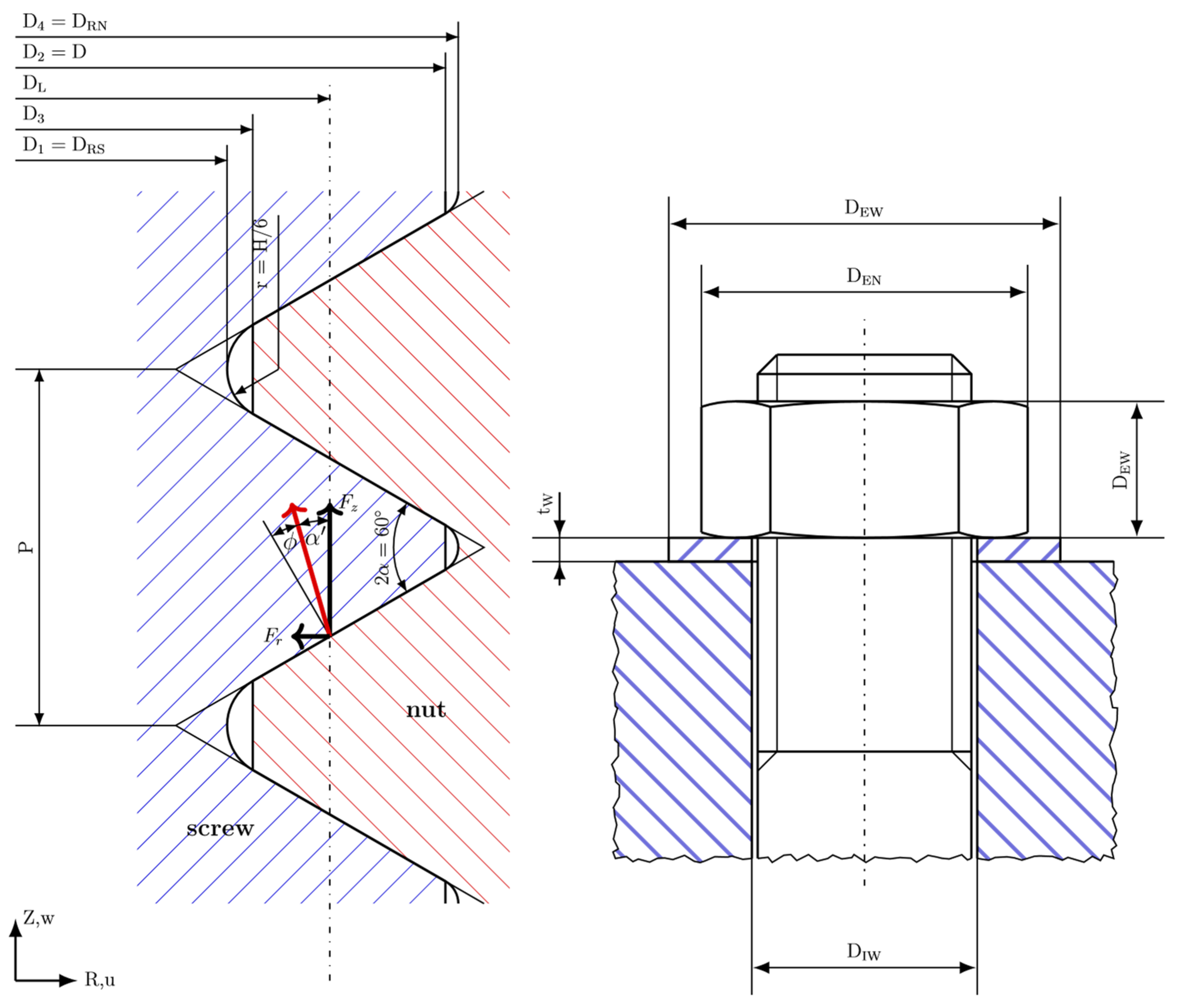
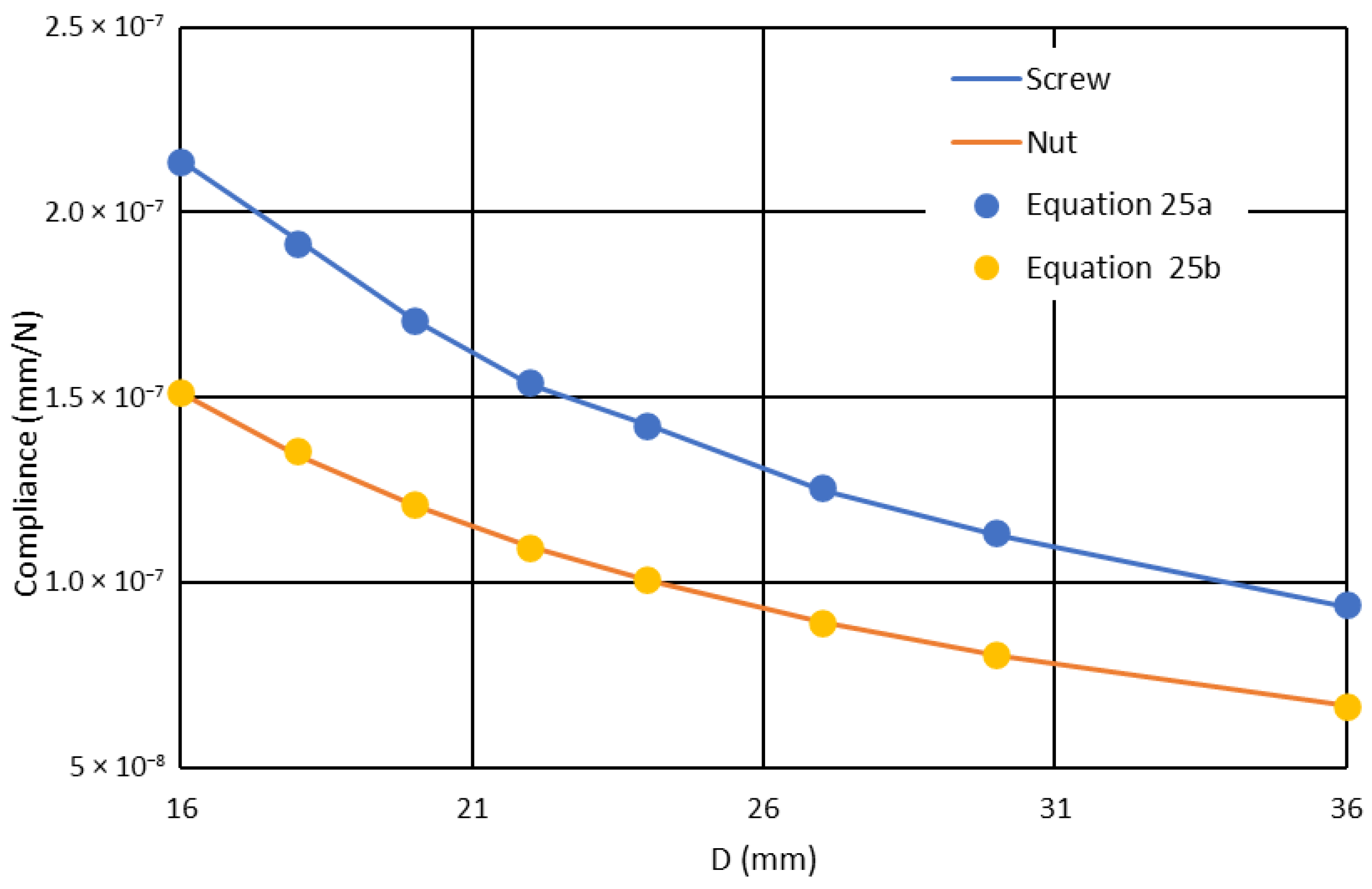
2.1. Elastic Behavior

As mentioned in the introduction, the proposed method extends Maduschka’s method published in 1936. This method considers the screw–nut assembly as a succession of axisymmetric collars attached to the body of the two elements as shown in Figure 1; the main condition to calculate the load distribution among the threads is that the pitch variation due to the external load is the same in the screw and nut for two adjacent collars. The method is explained in detail in [11,19] and with some formal modifications in [23]. In the following, we show the equations of Maduchka’s method with small differences necessary to improve the accuracy in the strain evaluation.
In a screw–nut assembly, as shown in Figure 2, the contact on the ith and (i + 1)th threads of the screw and the corresponding ones of the nut is active if the change in the pitch under the external load is:
pi = ∆pi
where the superscript ∗ indicates the nut. In the remainder of the paper, the following symbols will be used:
R, Z: Radial and axial directions
u, w: Radial and axial displacements
p: Pitch of the threads
σR, σZ: Stress components in radial and axial directions
εR, εZ: Strain components in radial and axial directions
Ftot: Axial total force applied to the screw and Fi: Force applied to the ith thread
n: Number of threads engaged
f: Friction factor
a: See Figure 2
E, ν: Modulo di Young and Poisson coefficient of the material
D: For the diameters of the screw and nut, see Figure 2
α = α a r c t a n ( f ) q i = F i F T o t
A s = π D L 2 4 : cross-section of the screw
Introducing the auxiliary variable φi, we have:
φ i = F i F T o t n
To simplify the treatment of the deformation state, the contact load between engaged threads is considered to be concentrated at the diameter DL (Figure 2). To use Equation (1), it is necessary to describe the stress and strain state in the cross-section of the screw and nut. For the screw, the forces acting on the ith thread are in the axial and radial direction, respectively (considering positive traction and negative compression):
F Z , i = F T o t 1 1 i φ k n   F R , i = F i tan α
Considering the screw as a smooth cylinder of diameter DL, the corresponding state of stress is:
σ Z , i = F T o t A S 1 1 i φ k n   σ θ , i = σ R , i = t a n α F i π D L · p
where the radial stress is constant along z from the contact i through i + 1. Applying Hooke’s law, the strain state gives the following pitch variations.
The first is due to the axial strain:
w i = p z , i = p · ε Z , i = p F T o t E A S 1 1 i φ k n + 2 ν t a n α F T o t φ i E π D 1 · n ,
For the radial strain, the radial and the azimuth stresses are typically calculated considering the case of a cylinder of infinite length under uniform radial pressure [4,11,12]. Due to the finite length of the screw and the fact that the radial force changes as it passes from the ith to the (i + 1)th thread, this is a rough approximation. Therefore, we introduced a factor K to account for this effect, deriving its value from the solution of the shrink fit case of a finite length solved by Rankin [36] in a closed form using Bessel functions. To simplify the calculation in the size range of the ISO thread, the original exact solution can be approximated via a third-degree polynomial:
K = A p D 1 3 + B p D 1 2 + C p D 1 + D
where the numerical values of the coefficients have been obtained via numerical interpolation (ISO thread)
A = 140.74   B = 112.46   C = −32.03   D = 4.63.
Then, the radial displacement is:
u i = D 1 2 K ε θ , i = D L 2 K E t a n α F T o t φ i π D L · p · n 1 ν ν F T o t A S 1 1 i φ k n
A negative radial displacement results in an apparent positive displacement, w. Finally, the pitch variation due to the radial displacement can be written as:
p u , i = t a n α D L F T o t 2 K E t a n α 1 ν π D L p · n φ i + 1 φ i + ν A S n φ i + 1
where the sign is positive if the pitch increases. The effect of the flexibility of the thread adds another term:
p F , i = F T o t π D L n δ π D L φ i + 1 φ i = F T o t n δ φ i + 1 φ i
in which δ is the compliance. Therefore, the total pitch variation on the screw is:
p i = p F T o t E A S 1 1 i φ k n + 2 ν t a n α F T o t φ i E π D L · n t a n α D L F T o t 2 K E t a n α 1 ν π D L p · n φ i + 1 φ i + ν A S n φ i + 1 + F T o t n δ · φ i + 1 φ i
Similarly, for the nut and with a resistant section equal to A N = π D E N 2 D L 2 4 , the stress state at the ith thread is:
σ Z , i * = F T o t A N 1 1 i φ k n
σ θ , i * = t a n α F i π D L · p D E N 2 + D 4 2 D E N 2 D 4 2 1 f n p = t a n α F T o t φ i n · π D L · p 1 f n p D E N 2 + D 4 2 D E N 2 D 4 2
σ R , i * = t a n α F i π D L · p 1 f n p = t a n α F T o t φ i n · π D L · p 1 f n p
The term f n p originates from the friction force applied at the contact surface between the washer and the nut. As a first approximation, this load is distributed uniformly along the n·p axial length. The radial and the azimuth stresses at the root of the thread are calculated using the equation describing a cylinder under uniform radial pressure. Then, using the strain state, it is possible to calculate the displacements using the following equation:
p i , w * = p · ε Z , i * = p F T o t E A N 1 1 i φ k n + ν E t a n α F T o t φ i n · π D L D E N 2 + D 4 2 D E N 2 D 4 2 1 1 f n p
where the signs derive from the displacements that are negative due to the compression and vice versa, and the pitch variation due to radial displacements is:
p u , i * = D 4 2 t a n α · t a n α F T o t φ i + 1 φ i E n · π D L · p 1 f n p D E N 2 + D 4 2 D E N 2 D 4 2 + ν + D 4 2 t a n α F T o t ν E A N φ i + 1
In addition, the pitch variation due to the compliance of the thread is:
p u , i * = F T o t n δ * φ i + 1 φ i
For the effect of the washer, a brief consideration is due. We can distinguish two cases: when DIW = D4, the uniform compression of the washer causes an axial displacement for the screw–nut assembly that does not alter the load distribution. In contrast, if DIW > D4, the washer does not support a part of the lower section of the nut. This condition, as shown in [19], can reduce the peak of the load distribution. In this paper, we consider only the case when DIW = D4. Then, the equation for the total pitch variation of the nut is:
p i * = p F T o t E A N ( 1 1 i φ k n ) + ν E t a n α F T o t φ i n · π D L 1 f n p D E N 2 + D 4 2 D E N 2 D 4 2 1 D 4 2 t a n α · t a n α F T o t φ i + 1 φ i E n · π D L · p ( 1 f n p ) D E N 2 + D 4 2 D E N 2 D 4 2 + ν + D 4 2 t a n α F T o t ν E A N φ i + 1 F T o t n δ * φ i + 1 φ i
The load distribution along the engaged threads can be calculated by equating the pitch variations of the screw (10) and of the nut (17).
Maduschka solved this problem by manipulating the equations and introducing a final finite difference equation of the second order that is nonhomogeneous with constant coefficients, using the index i as an independent variable, ranging from 1 to n. This way, a general integral can be defined together with a particular integral to obtain a closed-form function for the n engaged threads. This method drives to a general solution and is similar to that introduced some decades later in [37], but it is suitable for a threaded connection with uniform properties along the axial length. In the case of the elastic–plastic state of stress, this does not occur, and we developed an alternative numerical method. It is possible to write n − 1 equations similar to (1). To complete the system, we added the following global equilibrium equation:
1 n φ i = 1
All these equations form a system of linear equations that can be solved for the unknown φi. The method remains valid if the properties of the screw and nut vary along the engaged threads, for example, due to the plastic state of strain caused by an increasing external load. The only limitation is that the system must be applied whilst dividing the external load in steps in which the properties, which differ along the length of the connection, do not vary as a function of the load itself.
Examining the previously stated equations, the compliance of the threads plays a crucial role. Several different approaches to calculate thread flexibility are available in the literature. In the original papers by Maduschka and Sopwith [4,5], the flexibilities of the screw and the nut are considered equal, although the first uses a short beam model and the second the solution of a wedge loaded along the active flank. The method proposed in [38] is very interesting: it is set in the reference frame of Yamamoto’s load distribution and considers the contributions due to bending and shear added to the deformability of the root of the thread. In this paper, we use an alternative method based on the behavior of annular plates representing, respectively, the threads of the screw and the nut. The load applied to the thread has an axial and a radial component, but only the axial load significantly influences the deformation of the thread. In addition, we consider the load applied as a concentrated force at the medium radius of the contact surface. The axial load generates a shear deformation, neglecting the bending effect due to the short free length. Timoshenko and Woinowsky-Krieger [39] have given the formula for the shear compliance of an annular plate of constant thickness:
d w d r = χ F T o t 2 π t G
Assuming that χ = 1.2, as the shear section of the thread is a narrow rectangle, by integrating this equation, we obtain the displacement at the radius where the load is applied. In our case, the thickness t is a function of r, and we are looking for the compliance that is the displacement w due to the unit force. Then, the compliance of the screw and nut are, respectively:
δ S = 1.2 2 π G D 1 2 D L 2 d r r p 2 r D 1 2 t a n ) α ) ;
δ N = 1.2 2 π G D L 2 D 4 2 d r r p t L + 2 r D 1 2 t a n ) α )
These equations can easily be solved via numerical integration.

2.2. Elastic–Plastic Behaviour

When an increasing external load is applied, plastic strain starts when the von Mises stress at the root of the thread YS reaches the yield limit: σV M(YS) = σy. Increasing the external load, the plastic state extends from the two opposite roots of a thread towards the center of the cross-section YE; therefore, it is reasonable to assume that the thread is fully plastic when the von Mises stress reaches the yield limit at this final point: σV M(YE) = σy. When this condition occurs, the compliance of the thread goes to infinity, and the thread cannot support further load. Figure 3 shows the location of these two critical points for both the screw and the nut. In Appendix A, the procedure for calculating these two stresses is reported in detail. In conclusion, considering an elastic–perfectly plastic material with a yield stress σy, the initial plastic state begins when at the YS point the yield stress is reached:
Ftot = FYSFi = FYSiσV M(YS) = σy δ = δ(E) and σC = σyS
The plastic state occupies the entire root section of a thread when:
Ftot = FYEFi = FYEiσV M(YE) = σC = σy  δ = ∞
where Ftot and Fi are, respectively, the total external force and the force acting on the ith thread. The von Mises stress at the YE point is written as σC for brevity. When the von Mises stress at YS reaches σy, σC is equal to a given von Mises value σyS. The stress variation from the Yield Starting to the condition when the whole thread section is in plastic state, for the point C, can be written as:
∆σC = σy − σyS.
The compliance varies from the elastic value to infinity for the same stress range. When this occurs, the corresponding value of Fi becomes constant, and only the other threads support the increased external force. The process ends with an external load corresponding to the minimum value at which all the n threads or the root cross-section of the screw yields completely. In this process, it is reasonable that the nut stress state is lower than that of the screw.
During the plastic process, the compliance of the threads changes nonlinearly. This nonlinearity can be studied by dividing the range (FmaxFyS) into an appropriate number of steps, m, where:
F T o t = F M a x F y S m
where m is the value for which a stable solution can be obtained, and Fmax can be written as:
F M a x = σ y π D 1 2 4
For each step j and thread i, it is possible to calculate σ C i j for the screw and the nut and then the amplification factor for the compliance. For the jth step, the amplification factor H is:
H i j = σ C σ y σ C i j + σ C i j 1 2   a n d   H * j = σ C * σ y σ C i * j + σ C i * ( j 1 ) 2
For each step and in every thread, it is necessary to correct the compliance in Equations (20) and (21) using the factors:
δ i j = H i j δ   a n d   δ i * j = H i * j δ *
The process ends when:
σ y σ j C i + σ j 1 C i 2 = 0   o r < 0
This procedure, calculated for each thread, gives the modified set of compliances necessary to apply Maduschka’s method, as described in the previous paragraph, to calculate a load distribution factor q i + j for each step taking into account the thread flexibility. We can define q i + j as:
q i + j = F i j F T o t , j
The load is then:
F i j = F i j 1 + F t o t q i + j + q i + ( j 1 ) 2
For the jth load step, the total load distribution factor is given by the equation:
q i j = F i j F t o t j

3. Numerical Models

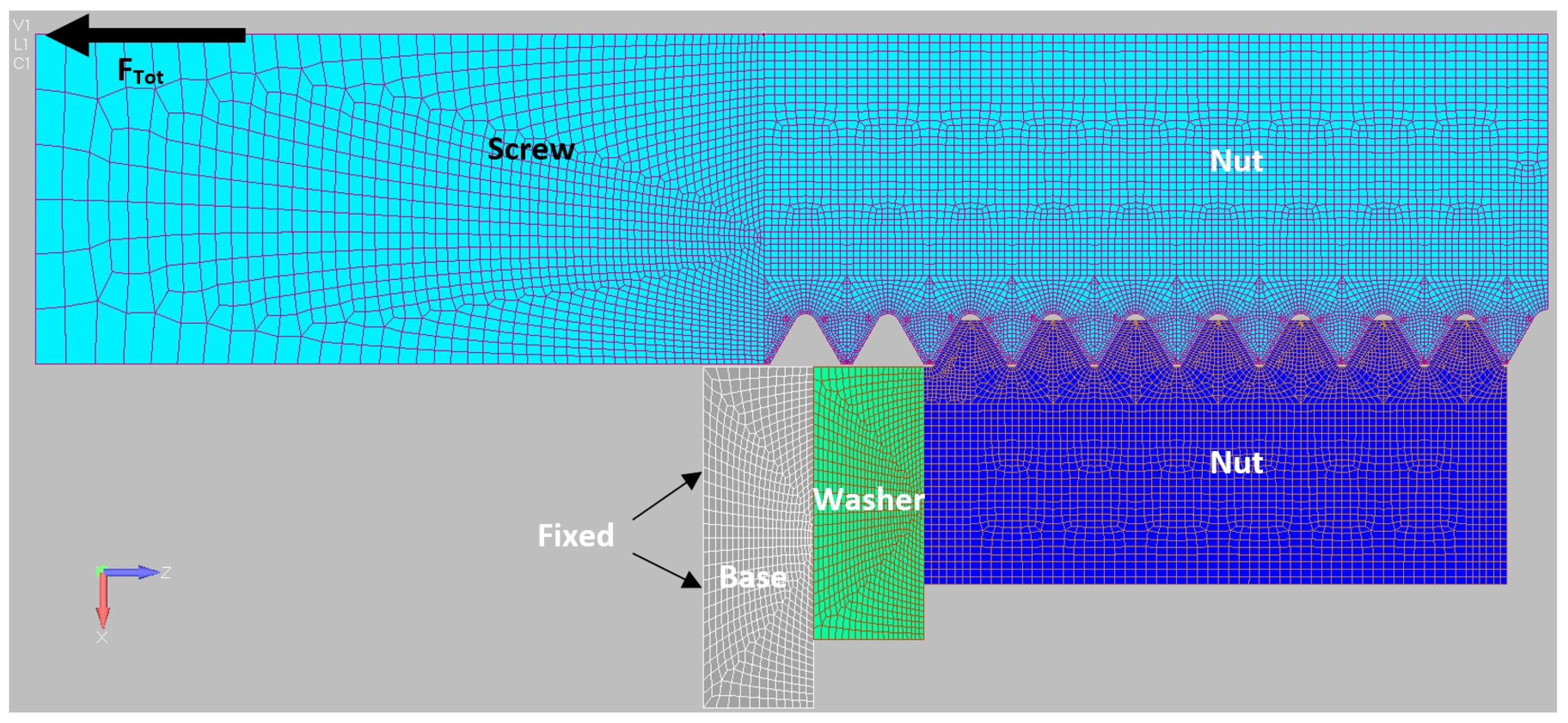
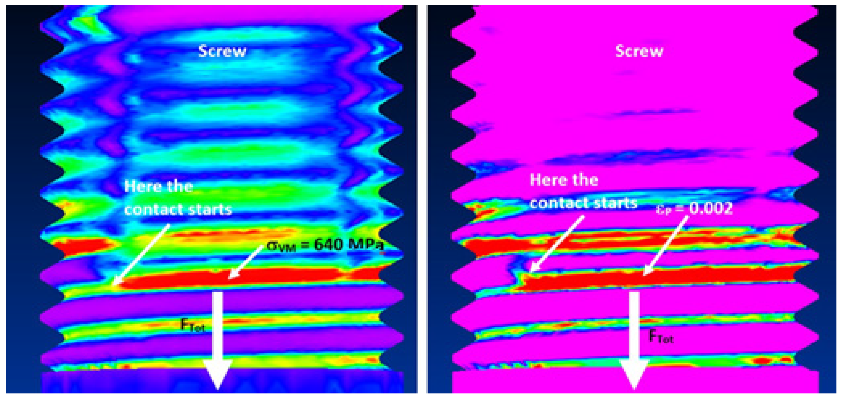
3.1. Axisymmetric FE Models

The accuracy of the proposed method has been verified by an extended numerical investigation using FE models generated by the pre-post processor FEMAP for the NASTRAN NX commercial program. In [25], the authors have shown that the results obtained using an axisymmetric FE model are in agreement with the results of the 3D analysis in both elastic and plastic states if the mesh has the same density. Anyway, the SNW assembly was modeled with axisymmetric and 3D FE models to obtain more confidence in the accuracy of the numerical check.
The contact between each pair of engaged threads has a friction connection and is only on the active flanks; there is clearance on the other flanks. The nut is placed on a washer with a friction contact condition along the common surface. The washer rests on a rigid foundation with a friction connection. In all the contacts, as well in the theoretical calculations, the friction coefficient is f = 0.25. This is the average value between 0.3 and 0.2 corresponding, respectively, to surfaces cleaned with loose rust removed or surfaces as rolled, according to [40].
The load is applied as an axial force on the base section of the screw. In Figure 4, the mesh of the axisymmetric models is shown. The elements used are of a parabolic axisymmetric type with material elastic–perfectly plastic. The contact condition is of the friction type with the coefficient f = 0.25 constant. The accuracy was checked by varying the number of elements on the fillet Nroot at the root of the threads, where the peak stress occurs. In the following Table 1, the comparison is resumed. The solution with Nroot = 12 was chosen as a good compromise between accuracy and calculation times. Once the reference mesh was chosen, it was adapted through size scaling and geometrical transformations to build equivalent models for all the screw diameters examined in both 2D and 3D. The 3D models have been built using parabolic solid elements. The analyses were performed using the advanced non-linear static solution using elastic–perfectly plastic material behavior and a friction unilateral contact for all the connections.
In addition, in the discussion of results, some comparisons made with the numerical, theoretical, and experimental results available in the references, validate the numerical models.
For example, in Figure 5 on the left, the von Mises stress contours are shown for an M24 screw with σy = 640 MPa, when the plastic strain starts. In Figure 5 on the right, the plastic strain contours are shown for the same case when the entire root section of the first engaged thread is in the plastic condition with εp0.002 = 0.2%. From the previous figures, as expected, the stress state in the nut is lower than that in the screw.

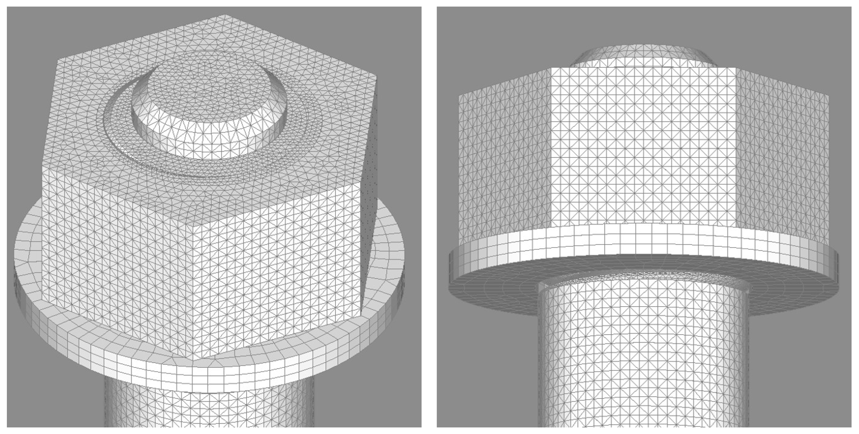
3.2. Three-Dimensional FE Models
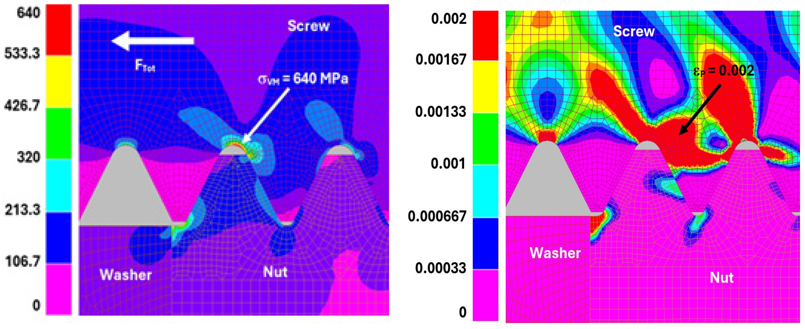
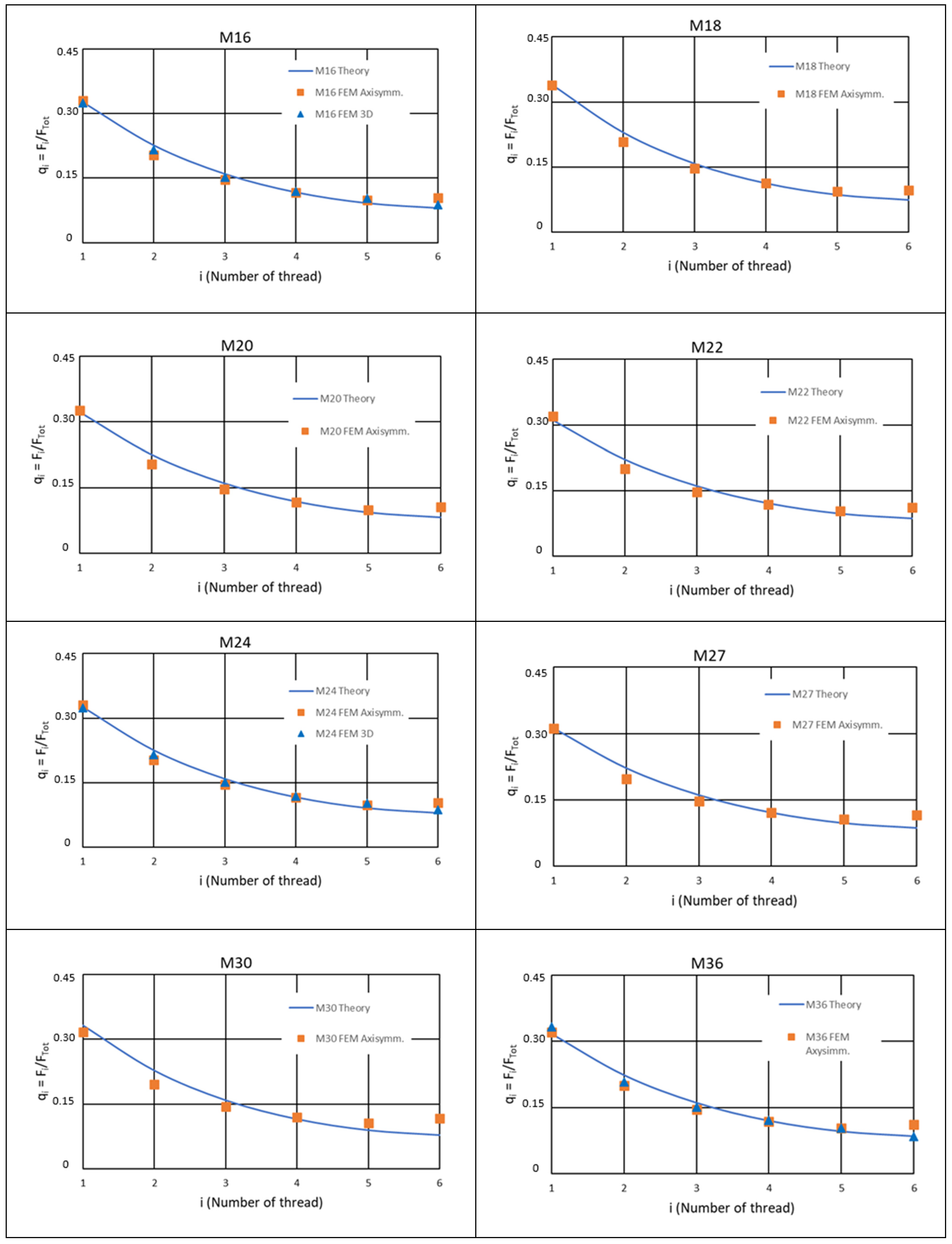
In addition, to obtain more reliable numerical results, some of the cases in Table 1 have been modeled with 3D FE models, particularly M16–M24–M27–M36, that is, those with a ratio D/p ranging between 8 and 9. The mesh of the models was built with the same density as the axisymmetric models around the root of the threads to minimize the unavoidable numerical differences. The FE model is shown in Figure 6.
The loading, contact, and restraint conditions were the same as those used for the axisymmetric models. As the geometry of the models represented the real arrangement accurately, the first and last engaged threads of the nut were not complete because the helix was cut by the plane of the external surfaces. To make the two types of models (axisymmetric and 3D) equivalent to the theoretical approach, the portion of these threads was neglected by introducing a clearance in the contact. If this effect must be included, the only revision to be introduced in the theoretical model is modifying the compliance of the first thread to take into account that the cross-section is tapered by the external ending plane. The analysis will be the same as in the case of axisymmetric models. In addition, for the 3D models, the reference mesh was adapted through size scaling and geometrical transformations to build equivalent models for all the diameters examined. In Figure 7, as an example, the von Mises stress contours (left) and the plastic strain contours are shown for the M27 screw when the yield starts, and the plastic strain ends on the first engaged thread.

4. Results

The modified Maduschka method was applied to the bolt–nut–washer assembly with six threads engaged, corresponding to the height of a standard nut. The characteristics of the examined cases are reported in Table 2.
Figure 8 includes the values of compliance for the screw and the nut, calculated according to Equations (20) and (21). Both compliances agree with two curves depending only on the nominal diameter D and pitch p. The equations of these curves are:
δ * = Γ / π D 5 8 p · c o s 30 °
δ * = Γ * / π D 5 8 p · c o s 30 °
Γ = 1.25 × 10 5   mm 2 / N ; Γ * = 8.88 × 10 6   mm 2 / N .
As the theoretical procedure is based on some simplifications and assumptions, the first step of the numerical verification was comparing the theoretical with the numerical values of the load distribution. The elastic load distribution factors for the sizes examined are shown in Figure 9 together with the corresponding values obtained from the FE analysis. Note that the curves are continuous, while the method calculates a single value for each thread, neglecting the variation along its length.
The agreement was very good for the first thread. In contrast, the maximum difference occurred for the second thread, although it remained acceptable; another difference was at the last thread. The first deviation arises because there is an interaction between the deformations of two adjacent threads that is completely neglected in the theoretical method. This interaction is less important in the following threads because the load after the third and fourth threads is smaller. The second deviation is because the compliance used was the same for all the threads, but the last was altered due to the nearly free section. The results are in line with those achieved by Sopwith [5] and Patterson [14].
The second check regards the initial yield load and the load at which the plastic strain occupies the entire root section at the first engaged thread. This comparison is in Figure 10, right and left, respectively, which includes the results obtained from the axisymmetric and 3D FE models. The agreement was good, showing that the deviations in the load distribution discussed above do not significantly affect the elastic–plastic behavior of the first thread. In addition, in Figure 10 on the right, also the curve of the load of the full plastic state in the minimum cross-section of the screw is included. This curve differs slightly from that of the full plastic state of the first thread showing that the f diameter and pitch values of the coarse pitch metric threads are near to the optimum for the ultimate strength when the material is elastic–perfectly plastic.
For the second thread, the load of the full plastic condition is practically equal to that of the first one. When the first thread is completely plastic, only five threads support the load increments. The behavior of an assembly with five or six active threads is very similar and can be represented by the following equation:
[1 − q1 (6a)]q1 (5a) ≈ q2 (6a)
where (6a) and (5a) indicate the assembly with six or five threads, respectively. Applying the proposed theoretical approach, described in Section 2.2, the progression of the plastic state for all the cases examined is shown in Figure 11, which also gives the results from the axisymmetric FE models. In this case, the agreement is also good.
Finally, because all the calculations were based on a unique configuration with friction coefficient f = 0.25 and number of threads n = 6, and the pitch associated with each diameter, as shown in Table 2, a variation in these parameters has been investigated to check the robustness of the theoretical procedure.
In Figure 12, the effects of the friction coefficient ranging from 0.15 through 0.35 on the initial and final yield conditions are reported using an M16 screw with p = 2 mm and n = 6.
In Figure 13, the effect of pitches ranging from 2 to 4 on the initial and final yield conditions is reported using an M24 screw with f = 0.25 and n = 6. Finally, in Figure 14, the effect of the number of engaged threads, ranging from 4 to 8, on the elastic load distribution is shown.
All the checks show a good agreement between the theoretical and numerical values, assessing the accuracy of the proposed procedure and its validity to simulate the elastic–plastic behavior of the SNW system. Considering the whole set of checks performed between the theoretical and numerical results, the differences are less than 5%.

5. Comparison with the Results Available in the Literature

Another independent validation of the results presented above, as well as of the accuracy of the proposed method, has been carried out using data available in the literature. It should be noted that a comprehensive investigation—whether theoretical, numerical, or experimental—of the elastic–plastic behavior of the metric screw–nut–washer assembly is currently lacking.
Regarding the elastic load distribution, as mentioned in the introduction, the accuracy of the Maduschka method was successfully validated in [11] using the photoelastic experiments conducted by Hetényi [9]. However, that study focused exclusively on Whitworth threads.
In Figure 15, the elastic load distribution obtained from our method is compared with the photoelastic results of Kenny & Patterson for an M30 thread, as well as with the theoretical solution provided by Sopwith [5]. The results show good agreement with the experimental data and are slightly more accurate than Sopwith’s theoretical predictions. While Sopwith’s solution provides a continuous distribution along the thread helix, our method yields a discrete set of values.
Figure 16 compares the elastic–plastic stress concentration factor (SCF) from our method with the numerical results obtained by Zhao [31] for the M30 thread. The SCF is defined as the ratio between the maximum principal stress at the root of the thread and the nominal stress, calculated as Ftot/As, with a yield stress of 150 MPa. The agreement is good, with a maximum deviation of +7% only at thread N° 6 while the others are less than 4%.
Additionally, we identified several relevant numerical and experimental results for thread diameters ranging from 16 mm to 36 mm with coarse pitches. From the available data, we selected those most relevant to the key parameters in the new method, including load distribution, elastic stiffness, and limit loads corresponding to the onset and completion of yielding.
Table 3 summarizes these values. Each dataset is categorized as theoretical, numerical, or experimental. Our theoretical results were then compared to these references. In cases where the thread parameters differed from those used in our study, appropriate calculations were executed; the specific numerical values are noted in the “Notes” column. A legend below the table explains the abbreviations used. The comparison results are expressed as the relative difference: (RrefRour)/Rref%. All the differences across the examined parameters fall within acceptable limits for engineering applications.
For the evaluation of [30], since our method terminates when the compliance of the SNW assembly reaches infinity, the ultimate load has been estimated, as a first rough approximation, by multiplying FYE by the ratio σu/σ.

6. Conclusions

An enhanced elastic–perfectly plastic method for calculating the load distribution in screw–nut assemblies is presented, extending Maduschka’s original method, which was limited to elastic deformation, as for Sopwith’s and Yamamoto’s approaches. Special attention was given to the calculation of thread compliance and the von Mises stress at both the fillet and the center of each thread. These considerations enabled the study of both the initial and final yield conditions, using a step-by-step numerical evaluation of the plastic state growth. The accuracy of the proposed method was validated through an extensive numerical investigation using axisymmetric and 3D finite element (FE) models for ISO threads ranging from M16 to M36. The robustness of the new procedure was tested under variations in parameters such as pitch, friction coefficient, and the number of engaged threads. All the results demonstrated a strong agreement between the theoretical predictions and numerical simulations. In addition, an independent verification has been performed using theoretical, numerical, and experimental data available in the literature, showing a good agreement.
In the configuration exposed in this paper, the proposed tool is valid for SNW assemblies where the nut is in compression. From an application perspective, equally important cases, involving nuts in tension, different types of threads, or joints in pressure pipes, will require adaptations. These do not affect the theoretical foundation of the method but will necessitate modifications to the governing equations.
Further enhancements are possible by incorporating additional parameters neglected in this study. One such improvement involves adopting a more sophisticated elastic–plastic material behavior, such as a bilinear stress–strain curve or more complex. Additional potential sources of inaccuracy derive from the lack of interaction between adjacent threads, both in terms of deformation and stress. In this context, accounting for the variation in the stiffness of the final thread could also improve the accuracy. Moreover, incorporating a nonlinear friction model, that accounts for the effects of the applied load and roughness of the surfaces in contact, would provide a more realistic representation of the physical phenomena.
Though we have tried to be as clear as possible, the complexity of the shape and structural behavior of the elements studied, unfortunately, does not allow further simplifications without a loss of accuracy. An important step to simplify could be summarizing the behavior with simplified formulas derived from a statistical analysis of a larger set of cases.
These results, in turn, support integration into more complex structural analyses, including digital twin applications where often it is crucial to reduce the size of sub modeling. Furthermore, the analysis revealed that the external load required to fully plasticize the first thread is close to the load that causes plasticization at the screw minimum cross-section. This finding suggests that ISO coarse pitch threads exhibit a nearly optimal configuration with respect to their plastic limit load. These advancements significantly contribute to the understanding and design of load-bearing systems, enhancing both operational performance and safety in structural engineering applications.

Author Contributions

Investigation: C.B., C.G. and M.E.B.; Conceptualization; C.B., C.G. and M.E.B.; Calculation and validation: C.B., C.G. and M.E.B. All authors have read and agreed to the published version of the manuscript.

Funding

The present work was partially developed as part of the research project “SMART MAINTENANCE OF INDUSTRIAL PLANTS AND CIVIL STRUCTURES BY 4.0 MONITORING TECHNOLOGIES AND PROGNOSTIC APPROACHES–MAC4PRO”, sponsored by BRIC-2018 of the National Institute for Insurance against Accidents at Work–INAIL (Italy).

Data Availability Statement

The original contributions presented in this study are included in the article. Further inquiries can be directed to the corresponding author.

Conflicts of Interest

The authors declare that they have no known competing financial interests or personal relationships that could have appeared to influence the work reported in this paper. On behalf of the authors Carlo Brutti 18 April 2025.

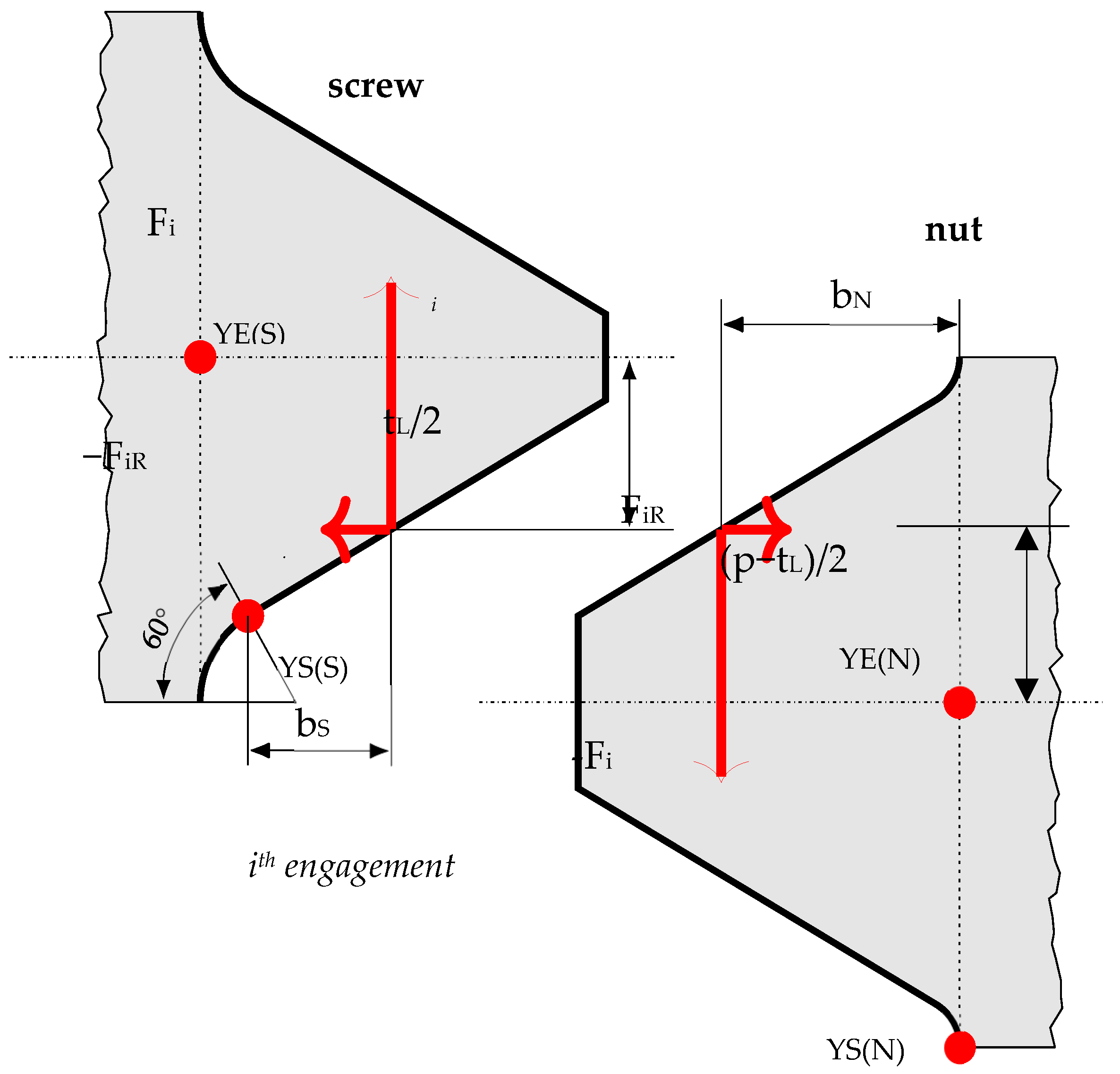
Appendix A. Stress Calculation

The two points where the stresses are calculated differ because, while in the fillet YS stress, all the stress components are present with the concentration effect, while in the center YE, the bending moment and the concentration factor are not active. Due to the bending and compression action, point YE is not exactly coinciding with the geometrical center of the thread.

Appendix A.1. Point YS(S)

Screw, at the root of the first engaged thread, see Figure 3.
σ R = F i b S F i t a n α γ t L W S K b S F i t a n α γ A R S ;   σ Z = F T o t 1 i 1 F k A Z S K Z S c o s 60 °
When a singularity occurs in a stress field, the stress state around the stress concentration due to the fillet is considered a plane strain case and then:
σ T = ν σ R + σ Z
The von Mises stress is then:
σ V M Y S = σ R 2 + σ Z 2 + σ T 2 σ R σ z σ R σ T + σ T σ z + 3 τ 2
where the symbols are:
W S = π D 1 + 2 R 1 c o s 60 ° p 2 R s e n 60 ° 2 6
A R S = π D 1 + 2 R 1 c o s 60 ° p 2 R s e n 60 °
A Z N = π 4 D 1 + 2 R 1 c o s 60 ° 2
The value of the stress concentration factor for the bending stress is determined according to the equations proposed by Winter and Hirth [41]:
K b S = 1.2 + 0.13 L q 1 1.21 + 2.3 L ;   L = p 2 R s e n 60 ° b S ;   q = p 2 R s e n 60 ° 2 R .
The value of the stress concentration factor for axial stress is determined according to the equation proposed by Castagnetti and Dragoni [32]:
K Z S = 1 + γ D D 1 2 R 0.556 ;   γ = p 3 π t S t a n h 3 π t S p .
In addition, since the maximum radial stress does not occur at the same point as the maximum axial stress, a variation in this last equation was assumed, according to cosθ, where θ = 60° is the angular distance of the two maximum points along the fillet.

Appendix A.2. Point YE(S)

Screw, at the center of the first engaged thread, see Figure 3.
σ R = σ T = F i t a n α γ A R o o t ;   σ Z = F T o t 1 i F k A M ;   τ = F i A R o o t ,
where the symbols are:
A R o o t = π D 1 p ;   A M = π 4 D M + D 1 2 2 ;   D M = D + D 3 2 .

Appendix A.3. Point YS(N)

Nut, at the root of the first engaged thread, see Figure 3.
σ R = F i b N F i t a n α γ p t L W N K b N + F i t a n α γ A R N ;   σ Z = F T o t 1 i 1 F k A Z N K Z N .
The stress state around the stress concentration due to the fillet is considered a plane strain and then:
σ T = F i t a n α γ π D 4 p D E N 2 + D 4 2 D E N 2 D 4 2 + ν σ R + σ Z .
The von Mises stress is then:
σ V M Y S = σ R 2 + σ Z 2 + σ T 2 σ R σ z σ R σ T + σ T σ z + 3 τ 2
where the symbols are:
W S = π D 4 p 2 6 ;   A R N = π D 4 p ;   A Z N = π D E N 2 D 4 2 4 .
The value of the stress concentration factor for the bending stress is determined according to the equation proposed in [41]:
K b N = 1.2 + 0.13 L q 1 1.21 + 2.3 L ;   L = p 2 r s e n 60 ° b N ;   q = p 2 r s e n 60 ° 2 r .
The stress concentration factor for the axial stress is calculated by neglecting factor 3 in γ, proposed in [32], as the thread here considered is the first one of the nut:
k z N = 1 + γ D 4 D 3 2 r 0.556 ;   γ = p π ( p t S ) t a n h π ( p t S ) p

Appendix A.4. Point YE(N)

Nut, at the center of the first engaged thread, see Figure 3.
σ R = σ T = F i t a n α γ p t L A R o o t ;   σ Z = F T o t A M ;   τ = F i A R o o t
where the symbols are:
A R o o t = π D 4 p ;   A M = π 4 D M + D 4 2 2 ;   D M = D + D 3 2
With von Mises stress equal to:
σ V M Y S = σ R 2 + σ Z 2 + σ T 2 σ R σ z σ R σ T + σ T σ z + 3 τ 2

References

  1. Strizhak, V.; Penkov, I. Distribution of axial load on bolt and nut threads. In International Symposium on History of Machines and Mechanisms Proceedings HMM 2000; Springer: Dordrecht, The Netherlands, 2000; pp. 101–110. [Google Scholar]
  2. Mackerle, J. Finite element analysis of fastening and joining: A bibliography (1990–2002). Int. J. Press. Vessel. Pip. 2003, 80, 253–271. [Google Scholar] [CrossRef]
  3. Croccolo, D.; De Agostinis, M.; Fini, S.; Khan, M.Y.; Mele, M.; Olmi, G. Optimization of bolted joints: A literature review. Metals 2023, 13, 1708. [Google Scholar] [CrossRef]
  4. Maduschka, L. Beanspruchung von schraubenverbindungen und zweckmäßige gestaltung der gewindeträger. Forsch. Geb. Ingenieurwesens A 1936, 7, 299–305. [Google Scholar] [CrossRef]
  5. Sopwith, D. The distribution of load in screw threads. Proc. Inst. Mech. Eng. 1948, 159, 373–383. [Google Scholar] [CrossRef]
  6. Yamamoto, A. The Theory and Computation of Threads Connection; Youkendo: Tokyo, Japan, 1980; pp. 39–54. [Google Scholar]
  7. Zhou, J.; Thai, H.T.; Ngo, T. Simplified finite element model for screwed connections with clip angle. Structures 2025, 74, 108479. [Google Scholar] [CrossRef]
  8. Zhang, D.; Gao, S.; Niu, S.; Liu, H. A prediction method for load distribution in threaded connections. J. Theor. Appl. Mech. 2018, 56, 157–168. [Google Scholar] [CrossRef]
  9. Hetenyi, M. A photoelastic study of bolt and nut fastenings. J. Appl. Mech. 1943, 10, A93–A100. [Google Scholar] [CrossRef]
  10. Kenny, B.; Patterson, E.A. The distribution of load and stress in the threads of fasteners-a review. J. Mech. Behav. Mater. 1989, 2, 87–106. [Google Scholar] [CrossRef]
  11. Brutti, C.; D’Eramo, M. Methods to evaluate load distribution in screw threads. In Proceedings of the 2th Canadian Conference of Applied Mechanics, Edmonton, AB, Canada, 31 May–4 June 1987; pp. 74–75. [Google Scholar]
  12. D’Eramo, M.; Cappa, P. An experimental validation of load distribution in screw threads. Exp. Mech. 1991, 31, 70–75. [Google Scholar] [CrossRef]
  13. Heywood, R. Tensile fillet stresses in loaded projections. Proc. Inst. Mech. Eng. 1948, 159, 384–398. [Google Scholar] [CrossRef]
  14. Patterson, E.; Kenny, B. Stress analysis of some nut-bolt connections with modifications to the external shape of the nut. J. Strain Anal. Eng. Des. 1987, 22, 187–193. [Google Scholar] [CrossRef]
  15. Dragoni, E. Effect of thread shape on screw stress concentration by photoelastic measurements. J. Offshore Mech. Arct. Eng. 1994, 116, 228–232. [Google Scholar] [CrossRef]
  16. Govindu, N.; Kumar, T.J.; Venkadesh, S. Design and optimization of screwed fasteners to reduce stress concentration factor. J. Appl. Mech. Eng. 2015, 4, 171. [Google Scholar]
  17. Calì, M.; Oliveri, S.M.; Biancolini, M.E. Thread couplings stress analysis by radial basis functions mesh morphing. In International Joint Conference on Mechanics, Design Engineering & Advanced Manufacturing; Springer: Cham, Switzerland, 2020; pp. 114–120. [Google Scholar]
  18. Fathalla, A.S.M.; Akhavan, F.A.; Moezzi, R.; Koloor, S.S.R. A numerical study of the effect of bolt thread geometry on the load distribution of continuous threads. J. Eng. Res. 2022, 10, 158–173. [Google Scholar] [CrossRef]
  19. Brutti, C. Load and stress distribution in screw threads with modified washers. J. Multidiscip. Eng. Sci. Technol. 2017, 4, 6523. [Google Scholar]
  20. Sensale, M.; Vendeuvre, T.; Schilling, C.; Grupp, T.; Rochette, M.; Dall’Ara, E. Patient-specific finite element models of posterior pedicle screw fixation: Effect of screw’s size and geometry. Front. Bioeng. Biotechnol. 2021, 9, 643154. [Google Scholar] [CrossRef]
  21. Cardelli, P.; Montani, M.; Gallio, M.; Biancolini, M.; Brutti, C.; Barlattani, A. Angulated abutments and perimplants stress: Fem analysis. Oral Implantol. 2009, 2, 3. [Google Scholar]
  22. Chen, W.; Liu, Z.; Chu, H.; Yan, X.; Li, Y. Nonlinear finite element analysis for axial load distribution of thread considering plastic deformation. J. Phys. Conf. Ser. 2024, 2819, 012057. [Google Scholar] [CrossRef]
  23. Wang, W.; Marshek, K. Determination of load distribution in a threaded connector with yielding threads. Mech. Mach. Theory 1996, 31, 229–244. [Google Scholar] [CrossRef]
  24. Fukuoka, T.; Takaki, T. Elastic plastic finite element analysis of bolted joint during tightening process. J. Mech. Des. 2003, 125, 823–830. [Google Scholar] [CrossRef]
  25. Sun, Y.J.; Liao, R.D. The effect of helix on the nonlinear analysis of threaded connection. Adv. Mater. Res. 2011, 148, 1741–1744. [Google Scholar] [CrossRef]
  26. Sawa, S.; Ishimura, M.; Omiya, Y.; Sawa, T. 3-D FEM stress analysis of screw threads in bolted joints under static tensile loadings. In Proceedings of the ASME 2014 International Mechanical Engineering Congress and Exposition IMECE 2014-38089, Montreal, QC, Canada, 14–20 November 2014. [Google Scholar]
  27. Zhang, D.; Wang, G.; Huang, F.; Zhang, K. Load-transferring mechanism and calculation theory along engaged threads of high-strength bolts under axial tension. J. Constr. Steel Res. 2020, 172, 106153. [Google Scholar] [CrossRef]
  28. Redondo, R.; Mehmanparast, A. Numerical analysis of stress distribution in offshore wind turbine m72 bolted connections. Metals 2020, 10, 689. [Google Scholar] [CrossRef]
  29. Jiang, X.; Li, Z.; Wang, Y.; Pan, F. Self-loosening behavior of bolt in curvic coupling due to materials ratcheting at thread root. Adv. Mech. Eng. 2019, 11, 168781401984113. [Google Scholar] [CrossRef]
  30. Zhang, D.; Gao, S.; Xu, X. A new computational method for threaded connection stiffness. Adv. Mech. Eng. 2016, 8, 1687814016682653. [Google Scholar] [CrossRef]
  31. Zhao, H. Stress concentration factors within bolt-nut connectors under elasto-plastic deformation. Int. J. Fatigue 1998, 20, 651–659. [Google Scholar] [CrossRef]
  32. Castagnetti, D.; Dragoni, E. Stress concentrations in periodic notches: A critical investigation of Neuber’s method. Mater. Werkst. 2013, 44, 364–371. [Google Scholar] [CrossRef]
  33. Grimsmo, E.L.; Aalberg, A.; Langseth, M.; Clausen, A.H. Failure modes of bolt and nut assemblies under tensile loading. J. Constr. Steel Res. 2016, 126, 15–25. [Google Scholar] [CrossRef]
  34. Zhang, M.; Sheng, Z.; Xiong, J.; Saren, Q.; Chen, X.; Zhang, Z. Accurate modeling of threaded connections and evaluation of contact surface distribution errors oriented to accurate digital twins. Measurement 2025, 247, 116821. [Google Scholar] [CrossRef]
  35. Mirasoli, G.; Brutti, C.; Groth, C.; Mancini, L.; Porziani, S.; Biancolini, M. Structural health monitoring of civil structures through fem high-fidelity modelling. IOP Conf. Ser. Mater. Sci. Eng. 2022, 1214, 012019. [Google Scholar] [CrossRef]
  36. Rankin, A. Shrink-fit stresses and deformations. J. Appl. Mech. 1944, 11, A77–A85. [Google Scholar] [CrossRef]
  37. Miller, D.L.; Marshek, K.M.; Naji, M.R. Determination of load distribution in a threaded connection. Mech. Mach. Theory 1983, 18, 421–430. [Google Scholar] [CrossRef]
  38. Lu, S.-K.; Hua, D.-X.; Li, Y.; Cui, F.-Y.; Li, P.-Y. Stiffness calculation model of thread connection considering friction factors. Math. Probl. Eng. 2019, 2019, 8424283. [Google Scholar] [CrossRef]
  39. Timoshenko, S.; Woinowsky-Krieger, S. Theory of Plates and Shells; McGraw Hill: New York, NY, USA, 1959. [Google Scholar]
  40. EN 1090-2:2018; Execution of Steel Structures and Aluminum Structures—Part 2: Technical Requirements for Steel Structures. iTeh standards: Newark, DE, USA, 2018.
  41. Winter, H.; Hirth, M. Tooth root resistance based on real stresses. VDI-Z 1974, 116, 119–426. (In German) [Google Scholar]
Figure 1. Threaded connection redrawn from the original paper of Maduschka [4].
Applmech 06 00042 g001
Figure 2. ISO metric thread and screw–nut–washer assembly.
Applmech 06 00042 g002
Figure 3. Location of critical stress points.
Applmech 06 00042 g003
Figure 4. Mesh of the axisymmetric models.
Applmech 06 00042 g004
Figure 5. (Left): Von Mises stress at yield starting condition. (Right): plastic strain at yield ending condition for the first thread engaged (M24; σy = 640 MPa).
Applmech 06 00042 g005
Figure 6. 3D FEM model.
Applmech 06 00042 g006
Figure 7. Three-dimensional FE model of M36; stress state when the Von Mises stress reaches the yield limit (left), yield ending (right) at the first thread.
Applmech 06 00042 g007
Figure 8. Values of elastic compliance used in the calculations.
Applmech 06 00042 g008
Figure 9. Value of load distribution factor for the all the sizes studied.
Applmech 06 00042 g009
Figure 10. Values of Ftot and F1 for the condition of yield starting (left) and ending (right).
Applmech 06 00042 g010
Figure 11. Load on the first thread during the elastic–plastic process for M16–M18–M20M22 (left) and M24–M27–M30–M36 (right).
Applmech 06 00042 g011
Figure 12. Effect of the friction coefficient on the yield starting (left) and ending (right) loads for M16.
Applmech 06 00042 g012
Figure 13. Effect of the pitch on the yield starting (left) and ending (right) loads for M24.
Applmech 06 00042 g013
Figure 14. Effect of the number of threads on the load distribution for M24.
Applmech 06 00042 g014
Figure 15. Comparison of load distribution of our method, Sopwith [5] and photoelastic results [10].
Applmech 06 00042 g015
Figure 16. Comparison of elastic plastic stress concentration factor of our method with numerical values from Zhao [31].
Applmech 06 00042 g016
Table 1. Check of accuracy of stress at the thread root vs. the number of nodes on the fillet; Von Mises stress in MPa.
SizeFTot (N)Nf = 8Nf = 10Nf = 12Nf = 14
M16267142.4149.1156.5156.1
M24663171.5179.2181.9182.2
M361424175.9179.0183.7184.0
Table 2. Size of bolt–washer–nut cases examined.
CasepD/pRrDeNHNtwDew
(mm) (mm)(mm)(mm)(mm)(mm)(mm)
M16280.2890.17325.413330
M182.57.20.3610.21728.616.5333
M202.580.3610.21731.816.5337
M222.58.80.3610.21732.816.53.542
M24380.4330.263819.5444
M27390.4330.2643.319.5447
M303.58.570.5050.30351224.556
M36490.5770.34658.226566
Table 3. Comparison with data available in the literature.
ParameterRef.TypeValueOur MethodE%Notes
q1 = F1/FTot[30]Th/El0.3000.305+1.7M24: f = 0.15; n = 7; HN = 21 mm
q1 = F1/FTot[30]Nu/EP0.2130.212−0.5M24: idem; σy = 673.7 MPa
FYE[30]EXP/EP250 kN253 kN+1.2M24: idem
FYu[30]EXP/EP319 kN322 kN+0.9M24: idem; σu = 856.9 MPa
q1 = F1/FTot[22]Nu/EP0.2020.201−0.5M16: f = 0.15; n = 7; σy = 480 MPa
FYE[22]Nu/EP90 kN86 kN−4.4M16: idem
FYE[33]EXP/EP149 kN157 kN+5.3M18: f = 0.20; n = 6; σy = 908 MPa
K(thread)[34]Exp/El5.23 × 106 N/mm5.37 × 106 N/mm+2.6M36
Legend: Th—theoretical; Nu—numerical; Exp—experimental; El—elastic; EP—elastic–plastic; SCF = σ1,Max/σN stress concentration factor; σN = Ftot/Acore.
Disclaimer/Publisher’s Note: The statements, opinions and data contained in all publications are solely those of the individual author(s) and contributor(s) and not of MDPI and/or the editor(s). MDPI and/or the editor(s) disclaim responsibility for any injury to people or property resulting from any ideas, methods, instructions or products referred to in the content.

