Analytical, Experimental, and Finite Element Study of Stress Concentration for Samples Printed on Masked Stereolithography Devices


Abstract
1. Introduction
2. Materials and Methods
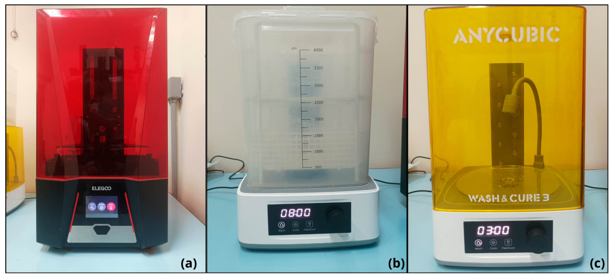
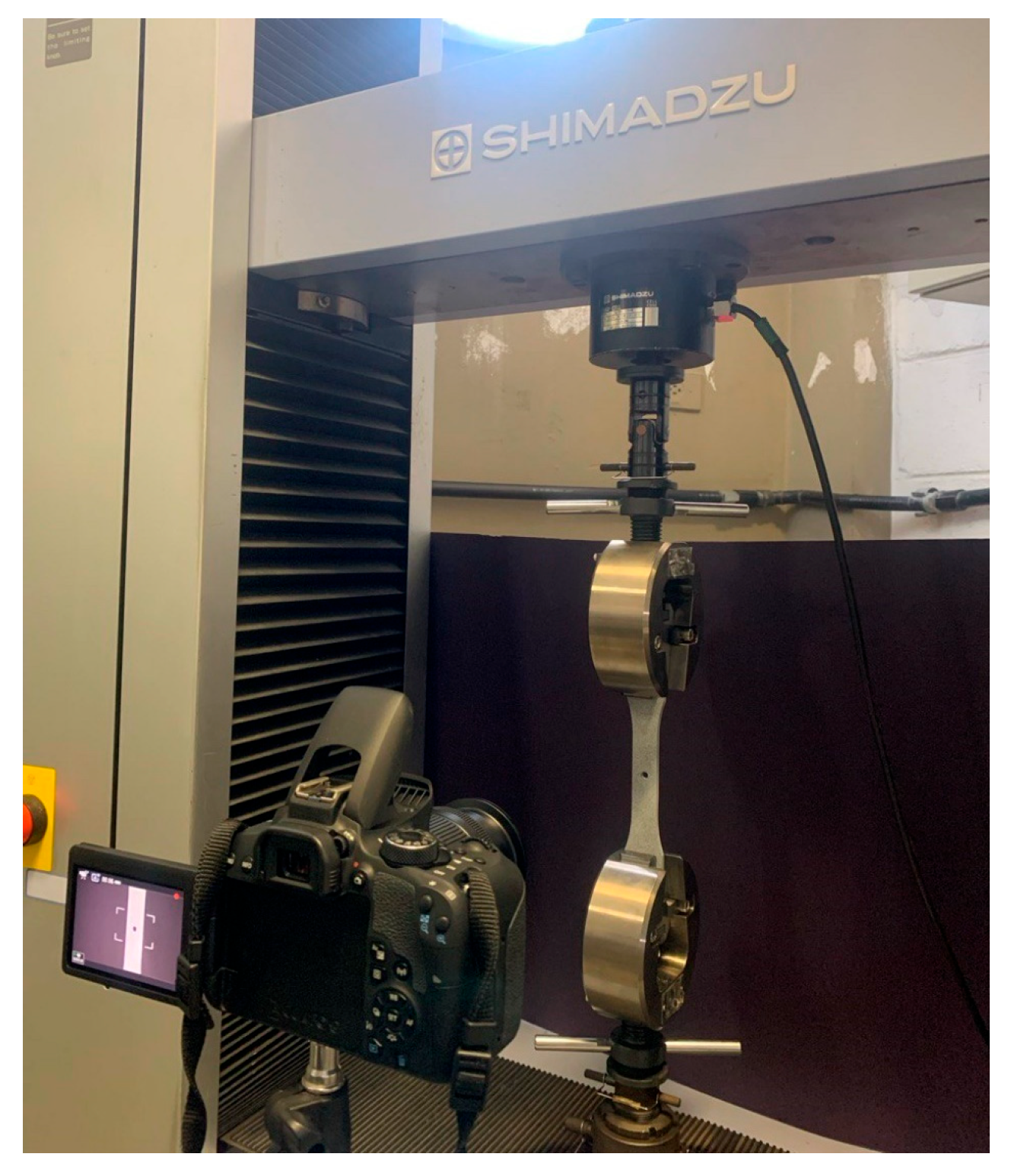
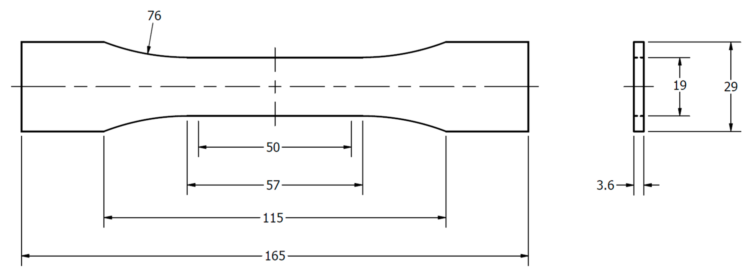
2.1. Testing Methodology: Test Specimen and Equipment
2.2. Testing
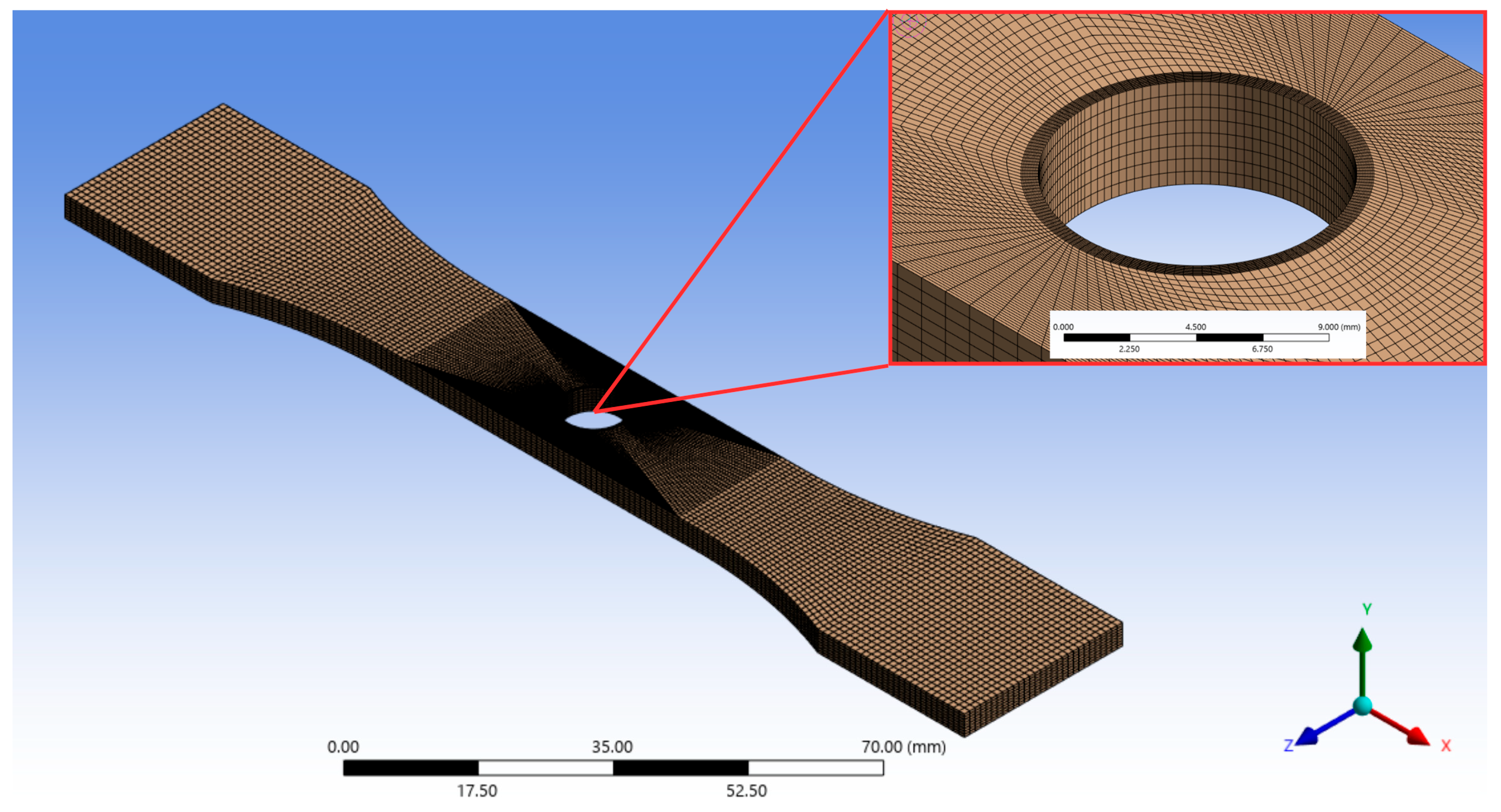
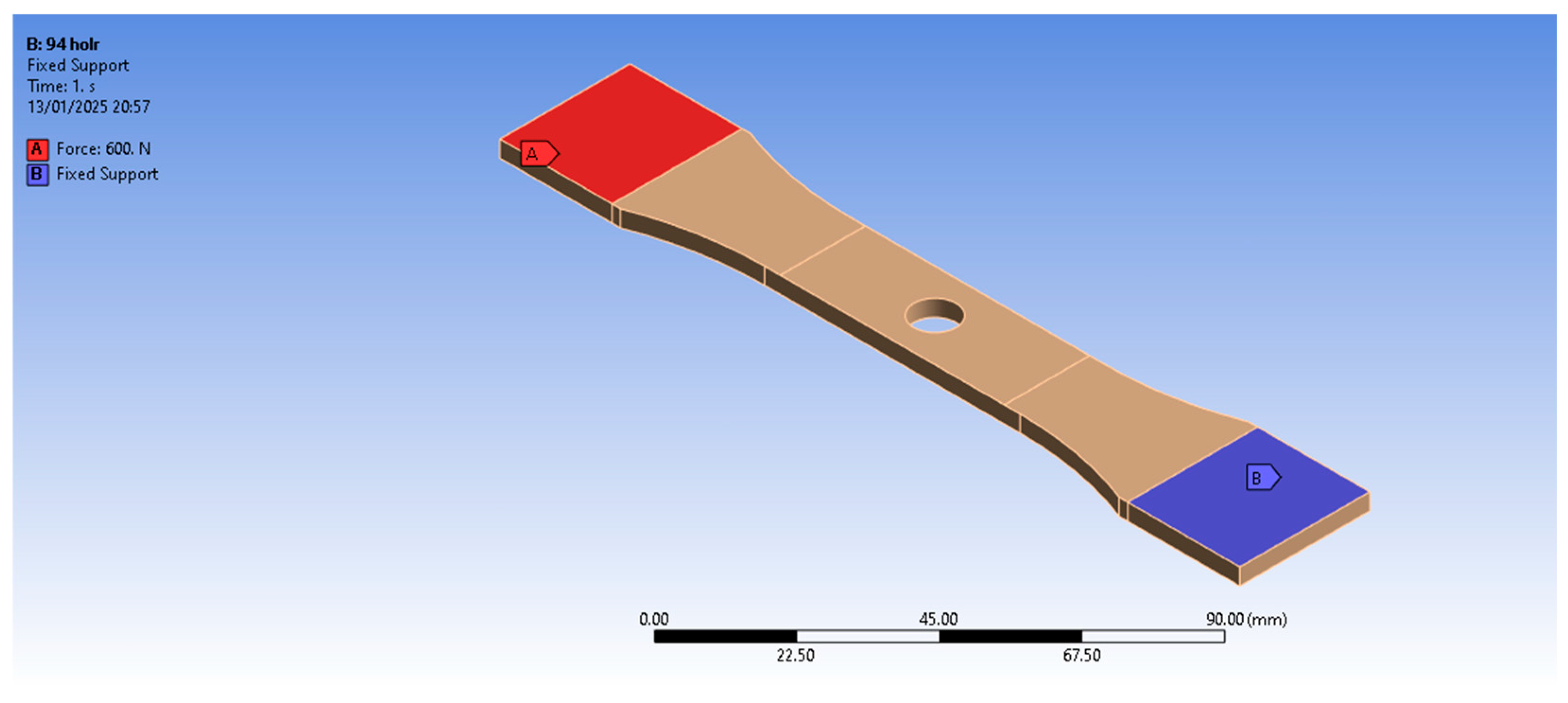
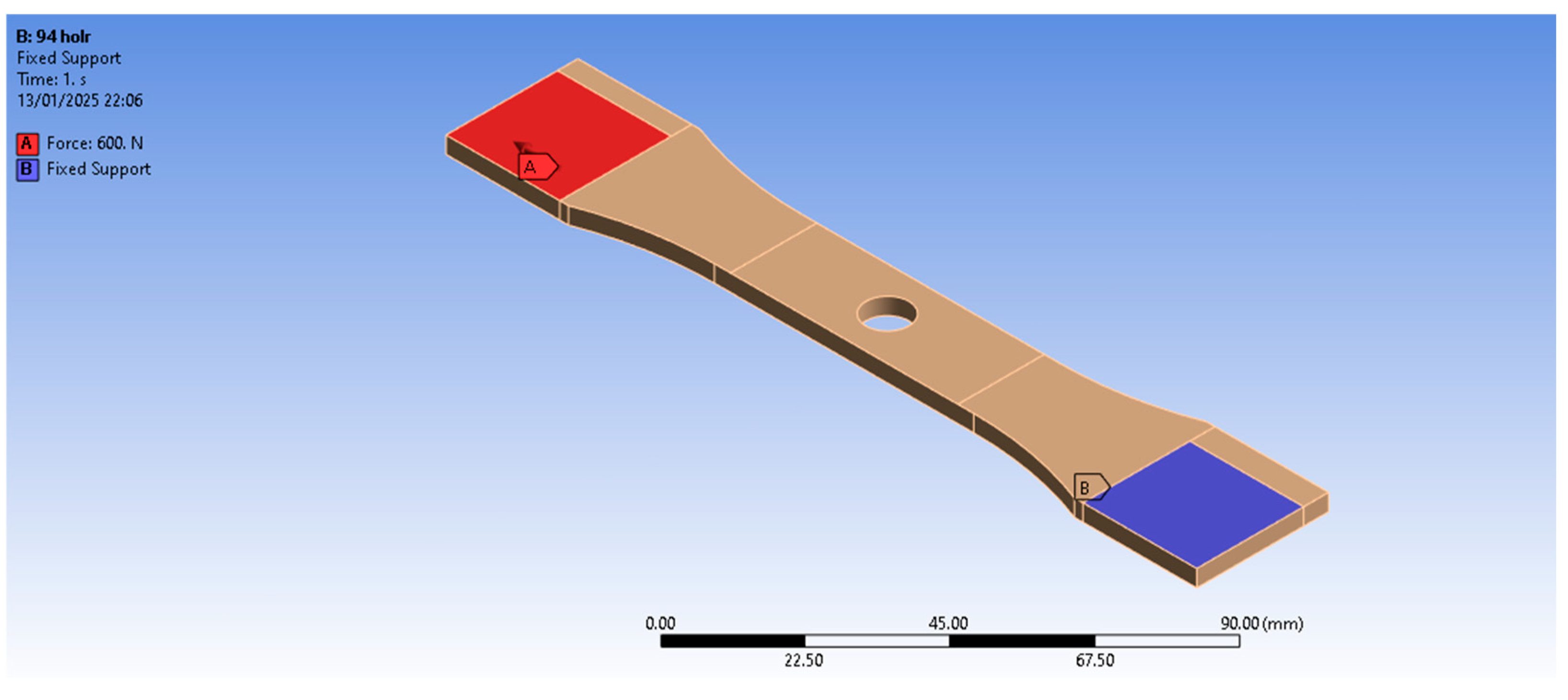
2.3. Finite Element Analysis
2.4. Analytical Method
3. Results and Discussions
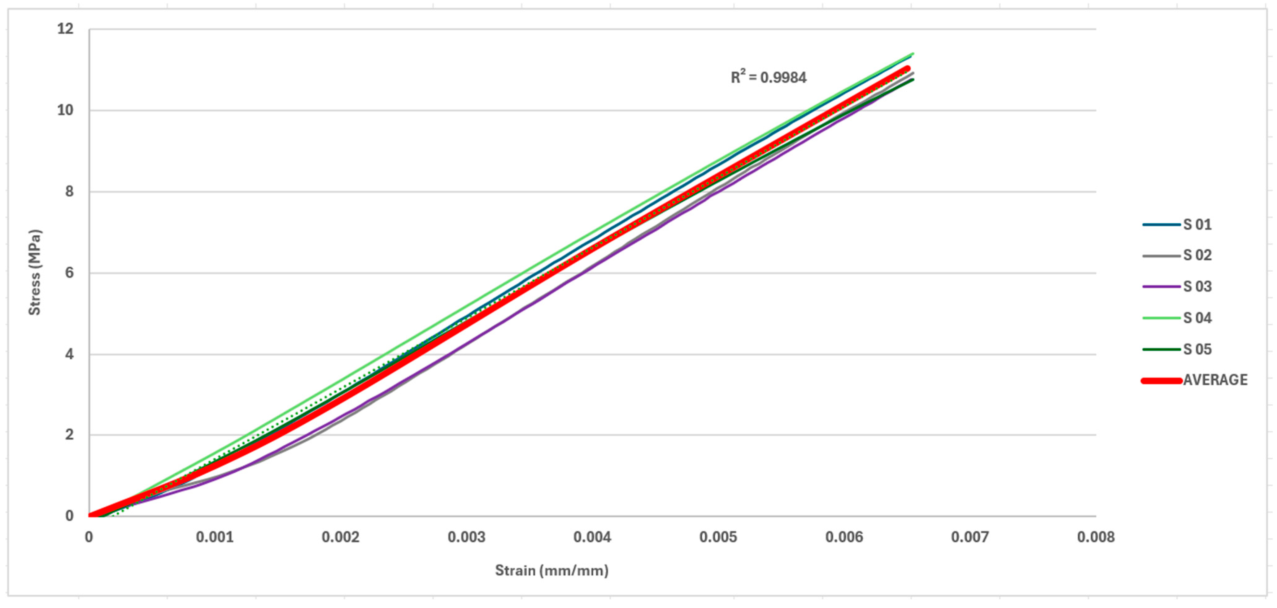
3.1. Test Specimen Subjected to Axial Load
3.2. Test Specimen Subjected to Eccentric Load Considering the Restriction of the Clamp
3.3. Test Specimen Subjected to Eccentric Load Disregarding the Clamp Restriction
4. Conclusions
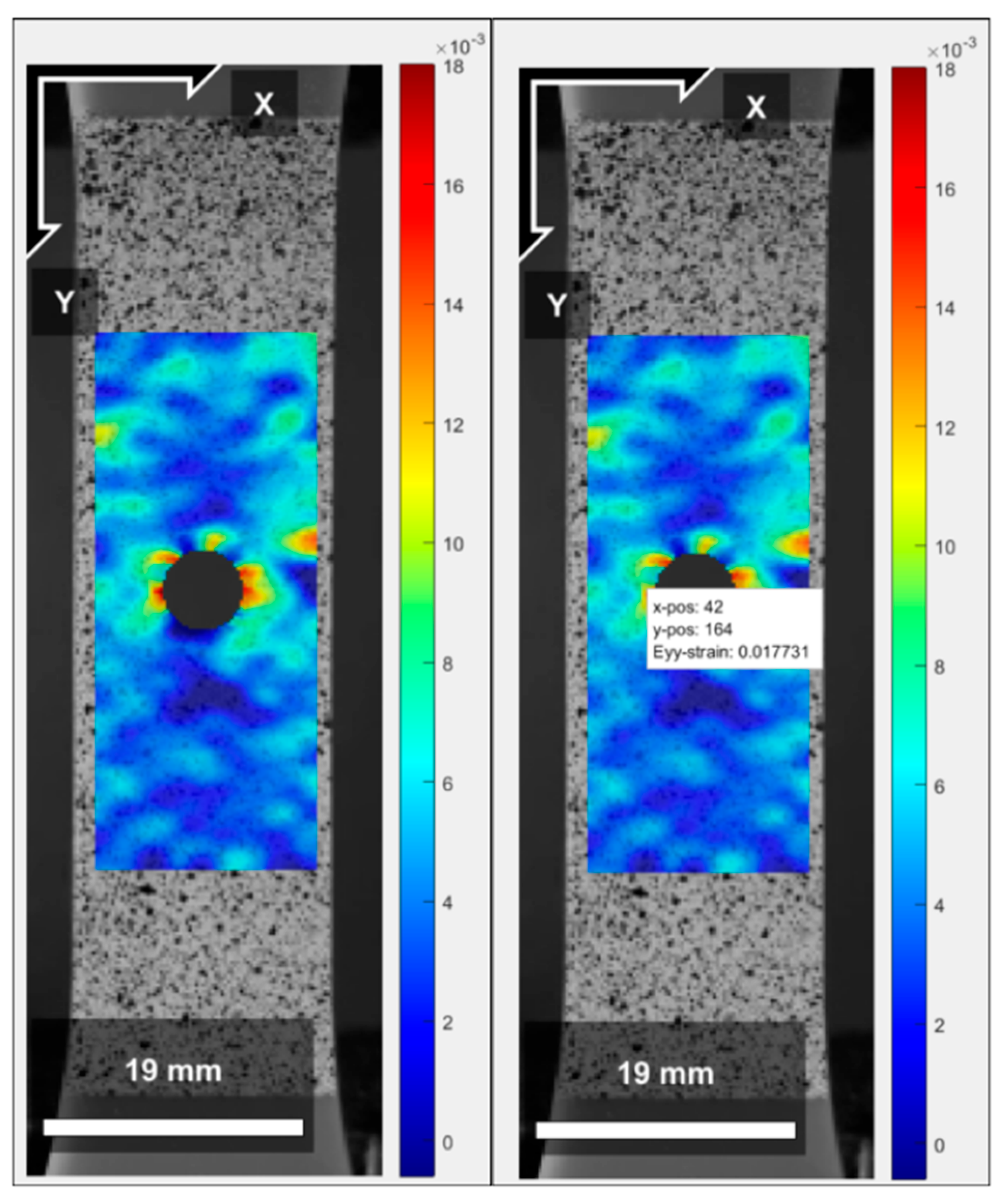
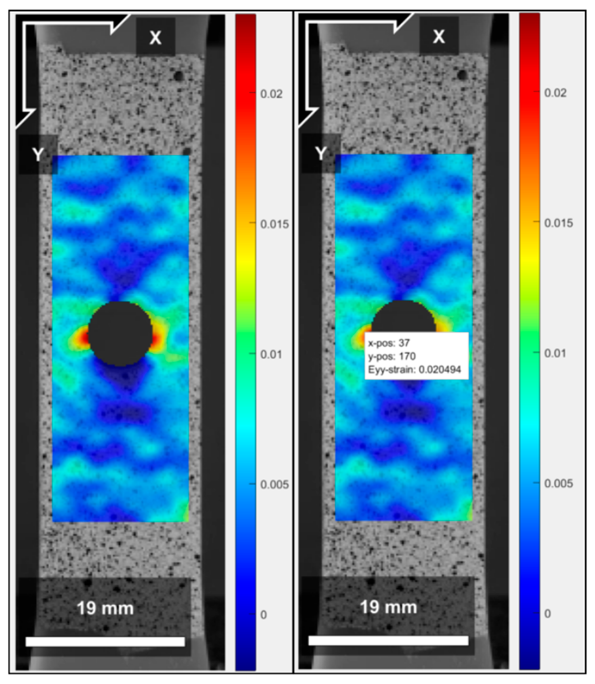
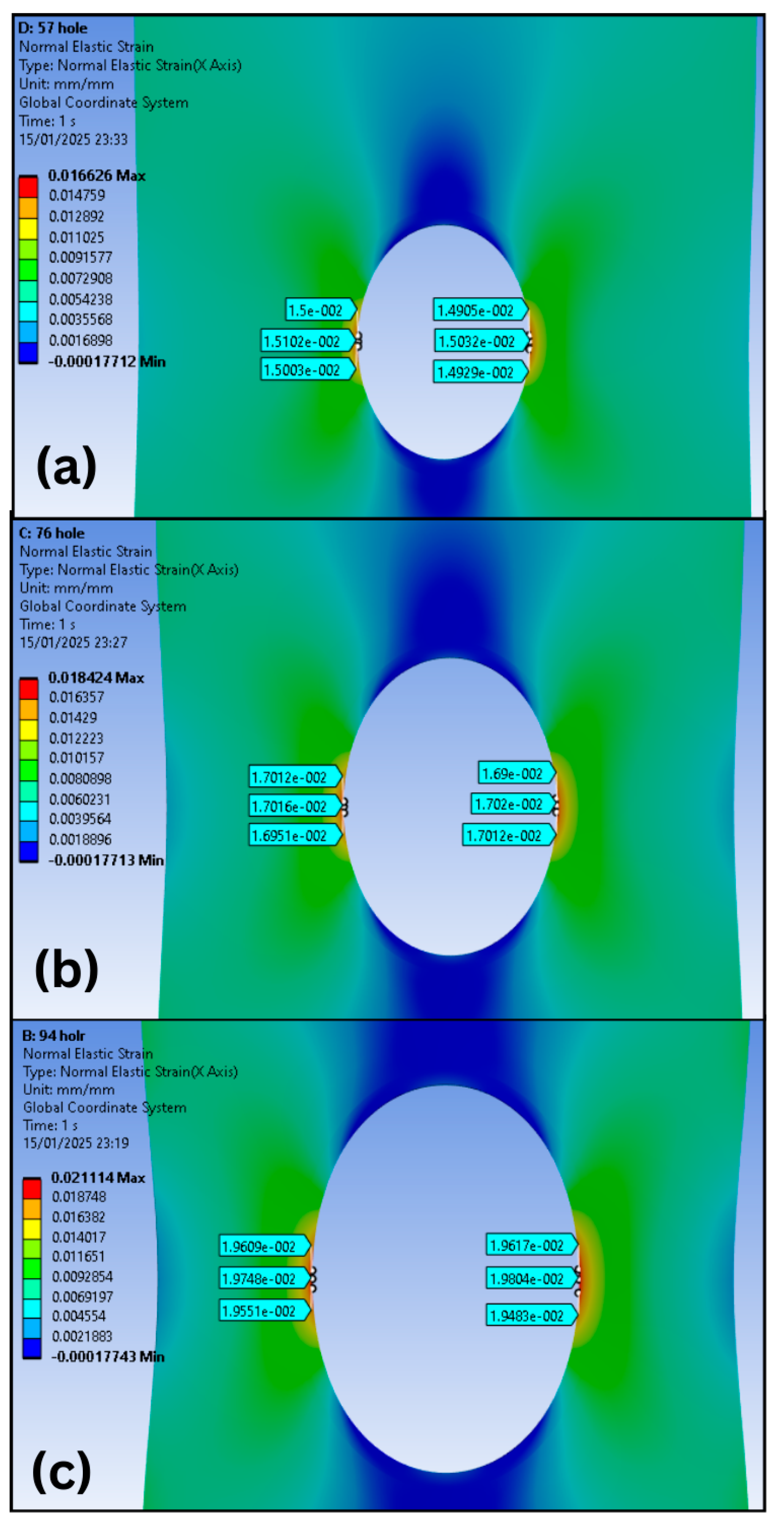
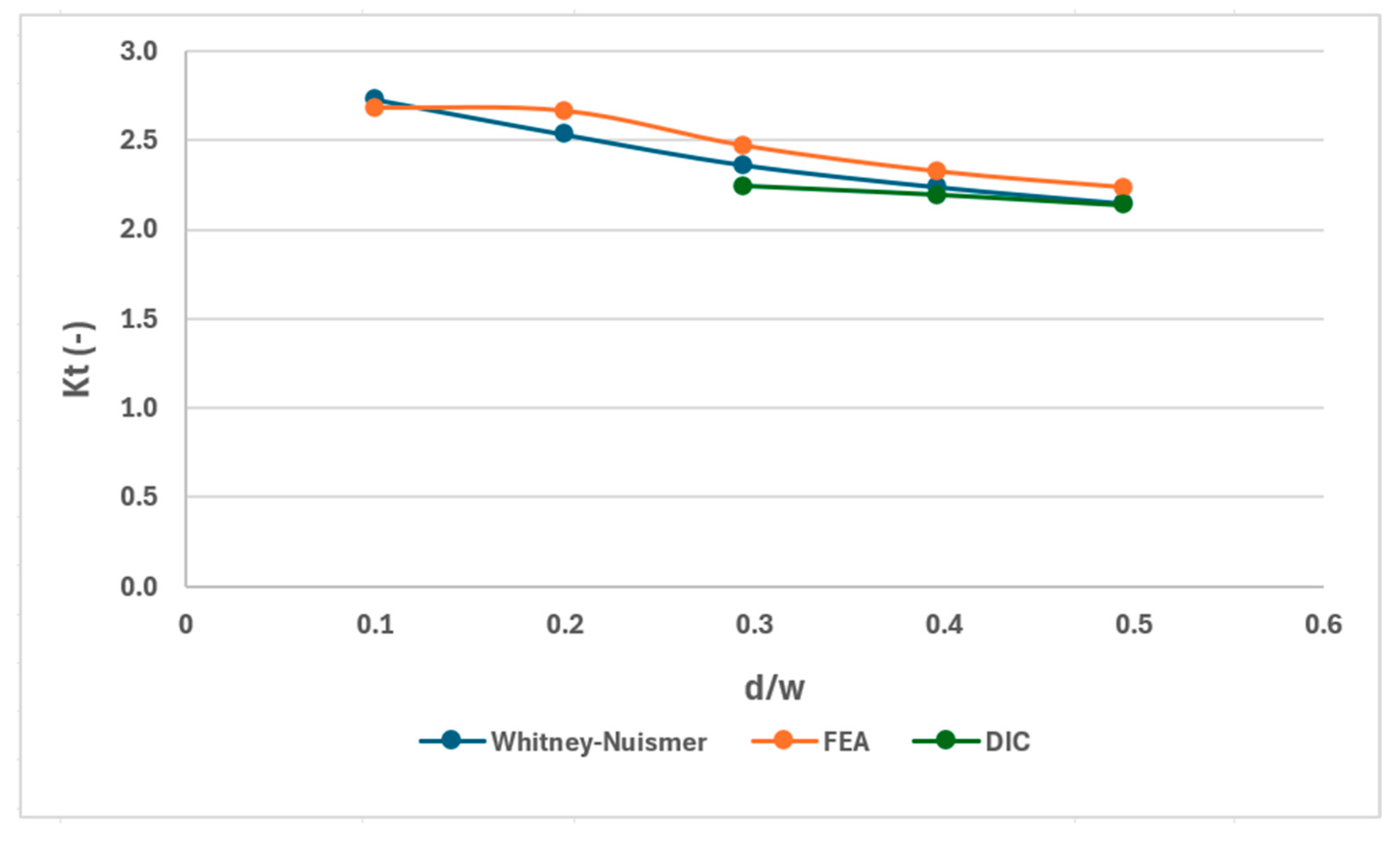
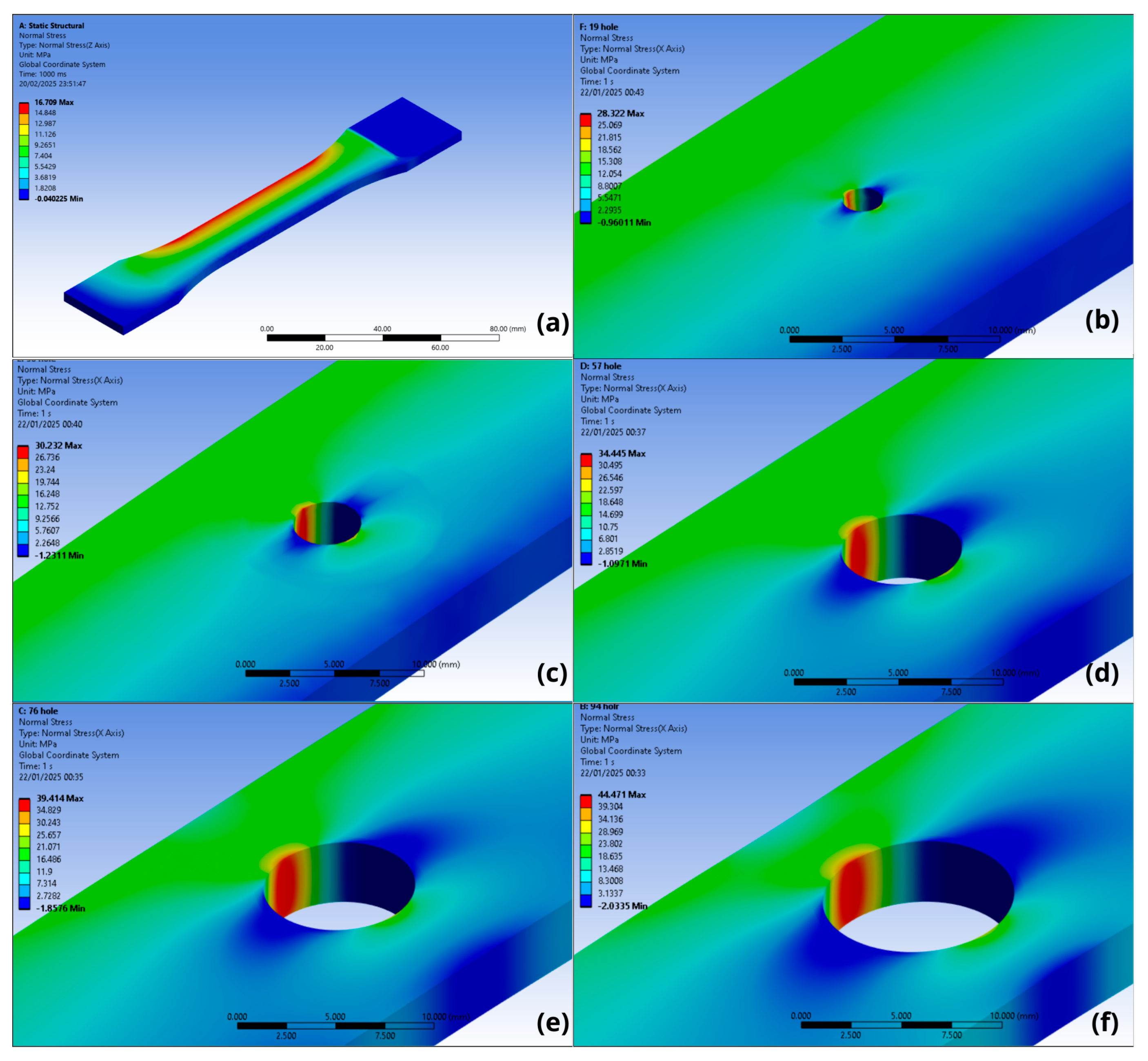
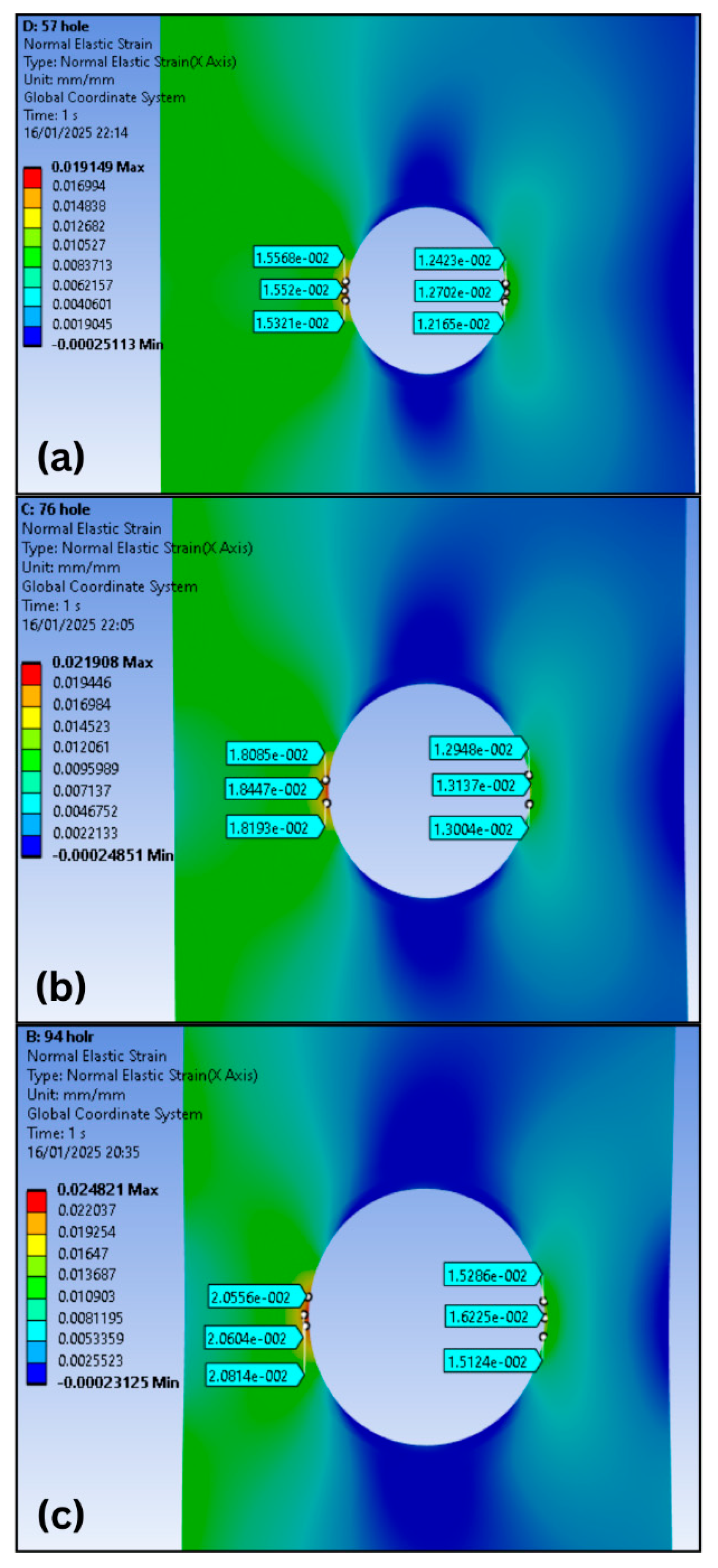
- It was possible to understand that, for axial load conditions, the stress concentration factor was consistent, as the results from the DIC, FEA, and Whitney–Nuismer methods showed very close values, with errors ranging from 0.42% to 5.25% (Table 9). Furthermore, by analyzing the strain fields generated by DIC (Figure 10, Figure 11 and Figure 12) and FEA (Figure 13), it is possible to see that they are very similar, generating symmetrical strain fields.
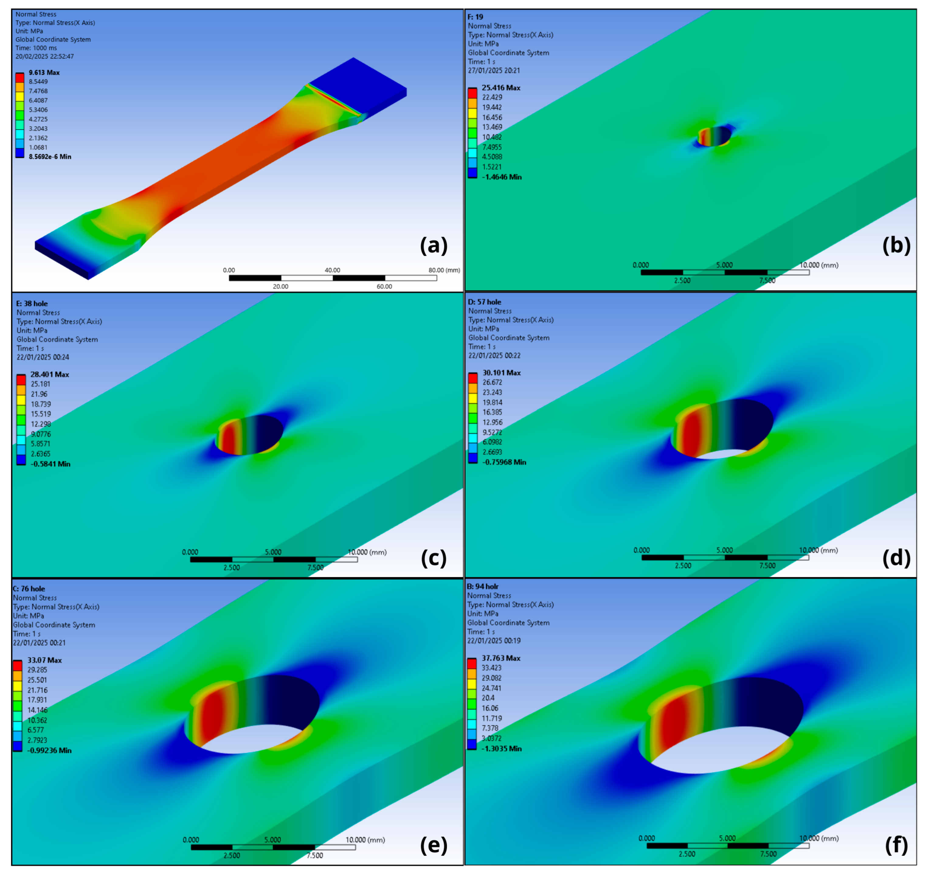
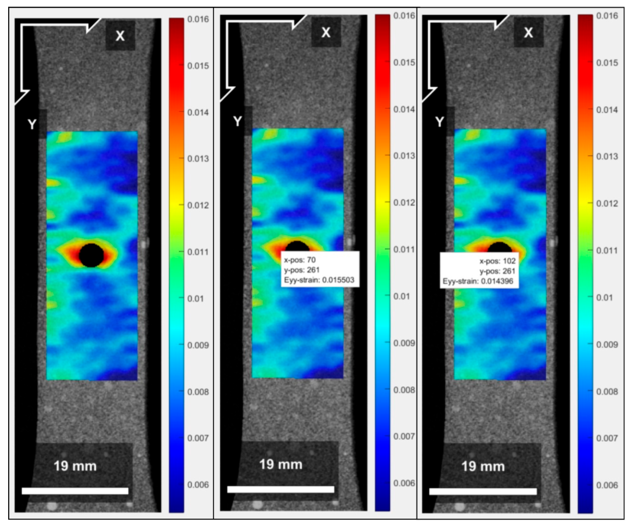
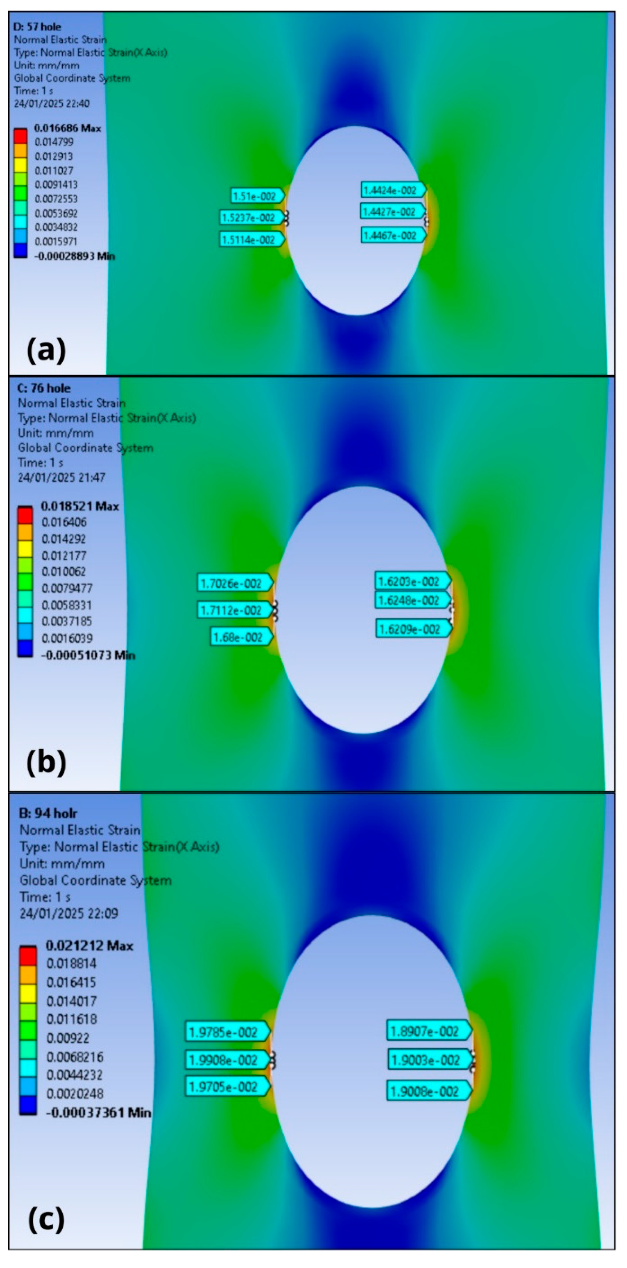
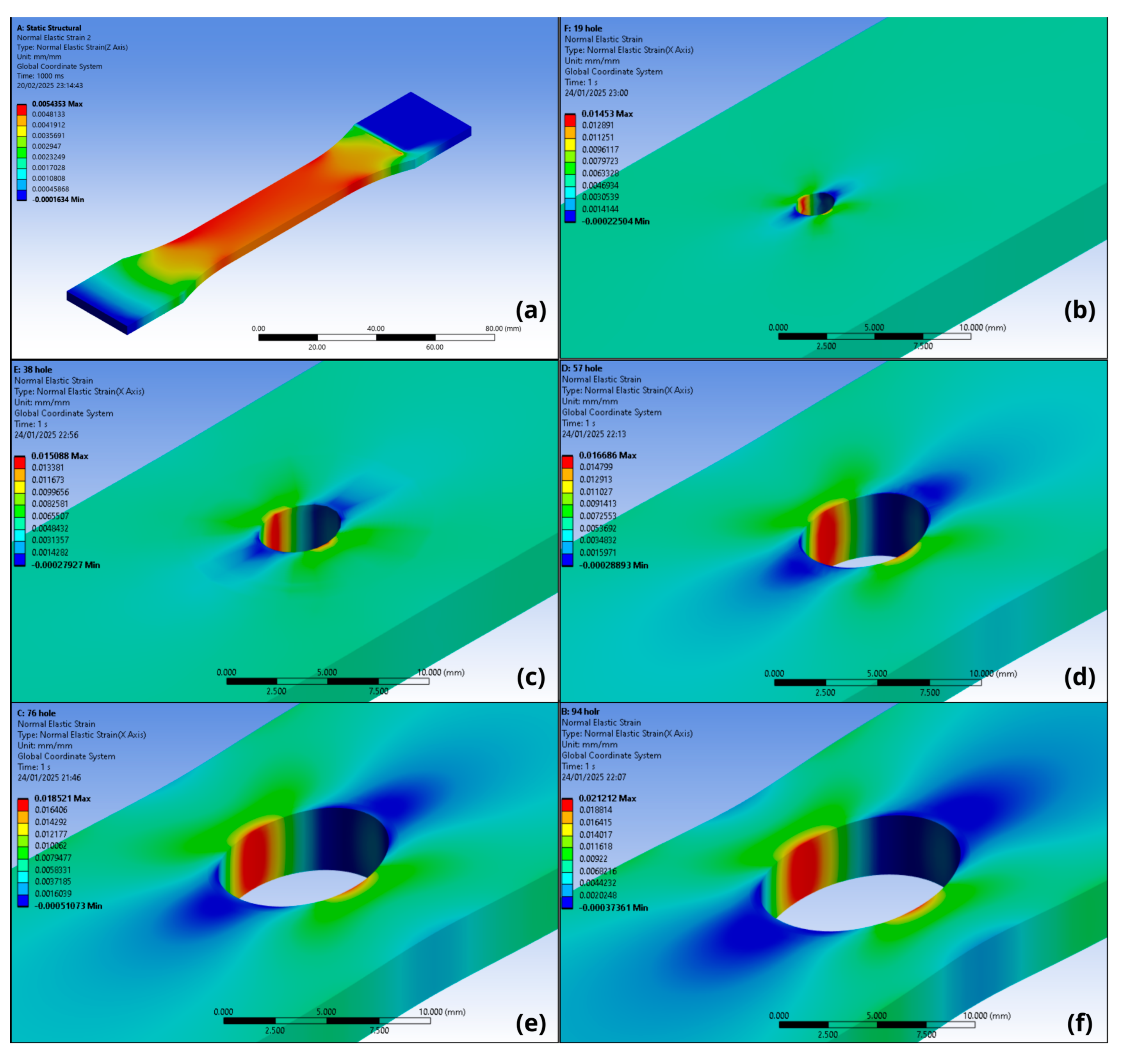
- For the eccentric load condition, comparing the figures generated by the DIC analysis (Figure 17, Figure 18 and Figure 19) and the FEA analysis (Figure 20), it can be seen that the stress fields are similar, and the restraint imposed by the clamp minimized the bending moment effect caused by the eccentric load, generating small differences when analyzing the strain on the left and right sides. The maximum error of 6.9% for the left side (Table 11) and 0.3% for the right side (Table 12) in the FEA and DIC comparison demonstrate that the simulation model represents what occurred in the test.
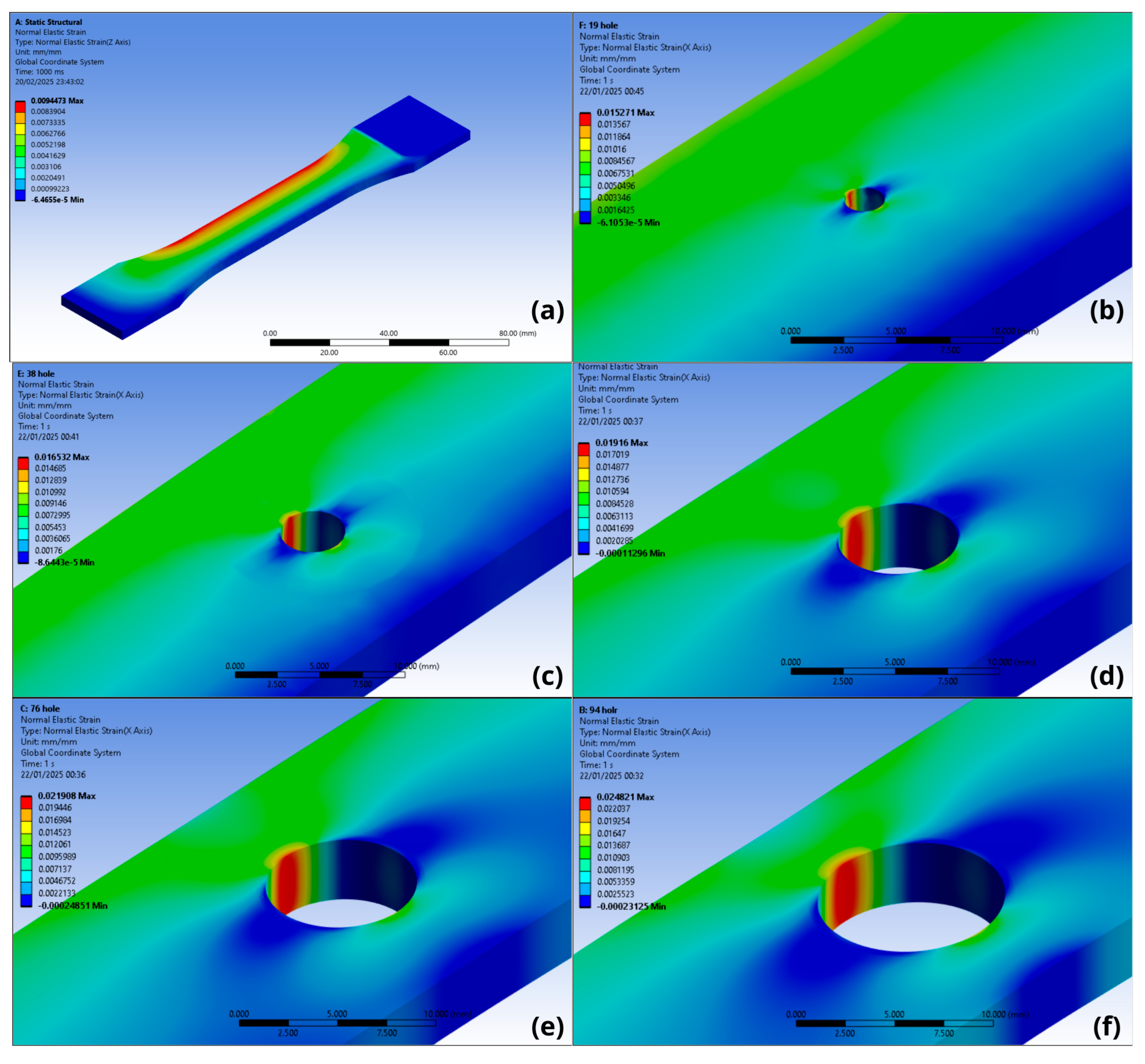
- For the analysis of the specimens using FEA without considering the clamp restriction effect, the combined load generated the effect of tensile and bending due to the bending moment. The moment acted freely, generating very expressive strain fields (Figure 23), which do not correspond to the strain fields generated by the experimental analysis (Figure 17, Figure 18 and Figure 19). The results show a relative error of around 20% presented in Table 15 and Table 16, comparing the strain from the FEA and DIC analysis for the right and left sides, indicating that this analysis does not reproduce what occurred in the test.
- The consistent results from the analysis of specimens subjected to axial loads demonstrate the quality of the method used. Furthermore, for the eccentric load analysis on the test specimens, it became evident that it is necessary to consider the restraint effect generated by the clamp.
- The results reinforce the robustness of the applied methods and present data on the mechanical characteristics of photopolymeric resins printed on mSLA devices, which are scarce in the literature. Understanding the mechanical behavior associated with notches in specimens printed by mSLA is essential to expanding the application of the method and making it viable for industrial applications, as it is possible to avoid material waste, improve part design, and ensure the safety of the developed product. To evaluate ways to improve the geometry of the part, as well as the impact of voids in this material, another study is in development, aiming to investigate the influence of the degree and type of void geometry applied to photopolymeric resin parts manufactured by this technique.
Author Contributions
Funding
Institutional Review Board Statement
Informed Consent Statement
Data Availability Statement
Acknowledgments
Conflicts of Interest
Abbreviations
| FEA | Finite Element Analysis |
| DIC | Digital Image Correlation |
| mSLA | Masked Stereolithography |
| UV | Ultraviolet |
| LED | Light-Emitting Diode |
| LCD | Liquid Crystal Display |
| srPET | Self-Reinforced Polyethylene Terephthalate |
| PMMA | Polymethyl Methacrylate |
| SCF | Stress Concentration Factor |
| PLA | Polylactic Acid |
| FDM | Fused Deposition Modeling |
| CAD | Computer-Aided Design |
| STL | Stereolithography |
| ASTM | American Society for Testing and Materials |
| ROI | Region of Interest |
References
- Kanishka, K.; Acherjee, B. Revolutionizing manufacturing: A comprehensive overview of additive manufacturing processes, materials, developments, and challenges. J. Manuf. Process. 2023, 107, 574–619. [Google Scholar] [CrossRef]
- Tamez, M.B.A.; Taha, I. A review of additive manufacturing technologies and markets for thermosetting resins and their potential for carbon fiber integration. Addit. Manuf. 2021, 37, 101748. [Google Scholar] [CrossRef]
- Wang, E.; Yang, F.; Shen, X.; Li, Z.; Yang, X.; Zhang, X.; Peng, W. Investigation and Optimization of the Impact of Printing Orientation on Mechanical Properties of Resin Sample in the Low-Force Stereolithography Additive Manufacturing. Materials 2022, 15, 6743. [Google Scholar] [CrossRef]
- Junk, S.; Bär, F. Design guidelines for Additive Manufacturing using Masked Stereolithography mSLA. Procedia CIRP 2023, 119, 1122–1127. [Google Scholar] [CrossRef]
- Valizadeh, I.; Weeger, O. Parametric visco-hyperelastic constitutive modeling of functionally graded 3D printed polymers. Int. J. Mech. Sci. 2022, 226, 107335. [Google Scholar] [CrossRef]
- Rahman, M.A.; Mohiv, A.; Tauhiduzzaman, M.; Kharshiduzzaman, M.; Khan, M.E.; Haque, M.R.; Bhuiyan, M.S. Tensile Properties of 3D-Printed Jute-Reinforced Composites via Stereolithography. Appl. Mech. 2024, 5, 773–785. [Google Scholar] [CrossRef]
- Riccio, C.; Civera, M.; Grimaldo Ruiz, O.; Pedullà, P.; Rodriguez Reinoso, M.; Tommasi, G.; Vollaro, M.; Burgio, V.; Surace, C. Effects of Curing on Photosensitive Resins in SLA Additive Manufacturing. Appl. Mech. 2022, 2, 942–955, Erratum in Appl. Mech. 2022, 3, 123–124. [Google Scholar] [CrossRef]
- Nowacki, B.; Kowol, P.; Kozioł, M.; Olesik, P.; Wieczorek, J.; Wacławiak, K. Effect of Post-Process Curing and Washing Time on Mechanical Properties of mSLA Printouts. Materials 2021, 14, 4856. [Google Scholar] [CrossRef]
- Minin, A.; Blatov, I.; Rodionov, S.; Zubarev, I. Development of a cell co-cultivation system based on protein magnetic membranes, using a MSLA 3D printer. Bioprinting 2021, 23, e00150. [Google Scholar] [CrossRef]
- Andreucci, C.A.; Fonseca, E.M.M.; Jorge, R.N. Biomechanics of a Novel 3D Mandibular Osteotomy Design. Designs 2024, 8, 57. [Google Scholar] [CrossRef]
- Braszkiewicz, M. Manufacturing of mechanical elements with properties of metamaterials using 3D printing technology. MATEC Web Conf. 2021, 338, 01002. [Google Scholar] [CrossRef]
- Kumar, S.; Bhushan, P.; Pandey, M.; Bhattacharya, S. Additive manufacturing as an emerging technology for fabrication of microelectromechanical systems (MEMS). J. Micromanuf. 2019, 2, 175–197. [Google Scholar] [CrossRef]
- Mahshid, R.; Isfahani, M.N.; Heidari-Rarani, M.; Mirkhalaf, M. Recent advances in development of additively manufactured thermosets and fiber reinforced thermosetting composites: Technologies, materials, and mechanical properties. Compos. Part A Appl. Sci. Manuf. 2023, 171, 107584. [Google Scholar] [CrossRef]
- Pyl, L.; Kalteremidou, K.-A.; Van Hemelrijck, D. Exploration of the design freedom of 3D printed continuous fibre-reinforced polymers in open-hole tensile strength tests. Compos. Sci. Technol. 2019, 171, 135–151. [Google Scholar] [CrossRef]
- de Morais, A.B. Open-hole tensile strength of quasi-isotropic laminates. Compos. Sci. Technol. 2000, 60, 1997–2004. [Google Scholar] [CrossRef]
- Whitney, J.M.; Nuismer, R.J. Stress Fracture Criteria for Laminated Composites Containing Stress Concentrations. J. Compos. Mater. 1974, 8, 253–265. [Google Scholar] [CrossRef]
- Mohamed Makki, M.; Chokri, B. Experimental, analytical, and finite element study of stress concentration factors for composite materials. J. Compos. Mater. 2017, 51, 1583–1594. [Google Scholar] [CrossRef]
- Wu, C.-M.; Kumar, S.; Lin, P.-C.; Chen, J.-C. Strain and stress concentration of ductile composites in full-range deformation by digital image correlation. Mech. Adv. Mater. Struct. 2023, 30, 3817–3825. [Google Scholar] [CrossRef]
- Teixeira Pinto, J.M.; Touchard, F.; Castagnet, S.; Nadot-Martin, C.; Mellier, D. DIC Strain Measurements at the Micro-Scale in a Semi-Crystalline Polymer. Exp. Mech. 2013, 53, 1311–1321. [Google Scholar] [CrossRef]
- Belloni, V.; Ravanelli, R.; Nascetti, A.; Di Rita, M.; Mattei, D.; Crespi, M. py2DIC: A New Free and Open Source Software for Displacement and Strain Measurements in the Field of Experimental Mechanics. Sensors 2019, 19, 3832. [Google Scholar] [CrossRef]
- Arabul, E.; Lunt, A.J.G. A Novel Low-Cost DIC-Based Residual Stress Measurement Device. Appl. Sci. 2022, 12, 7233. [Google Scholar] [CrossRef]
- Saleh, M.N.; Wang, Y.; Yudhanto, A.; Joesbury, A.; Potluri, P.; Lubineau, G.; Soutis, C. Investigating the Potential of Using Off-Axis 3D Woven Composites in Composite Joints’ Applications. Appl. Compos. Mater. 2017, 24, 377–396. [Google Scholar] [CrossRef]
- Aidi, B.; Philen, M.K.; Case, S.W. Progressive damage assessment of centrally notched composite specimens in fatigue. Compos. Part A Appl. Sci. Manuf. 2015, 74, 47–59. [Google Scholar] [CrossRef]
- Luo, J.; Luo, Q.; Zhang, G.; Li, Q.; Sun, G. On strain rate and temperature dependent mechanical properties and constitutive models for additively manufactured polylactic acid (PLA) materials. Thin-Walled Struct. 2022, 179, 109624. [Google Scholar] [CrossRef]
- Goodarzi Hosseinabadi, H.; Bagheri, R.; Avila Gray, L.; Altstädt, V.; Drechsler, K. Plasticity in polymeric honeycombs made by photo-polymerization and nozzle based 3D-printing. Polym. Test. 2017, 63, 163–167. [Google Scholar] [CrossRef]
- Tanabi, H. Investigation of the shear properties of 3D printed short carbon fiber-reinforced thermoplastic composites. J. Thermoplast. Compos. Mater. 2022, 35, 2177–2193. [Google Scholar] [CrossRef]
- Tang, C.; Liu, J.; Yang, Y.; Liu, Y.; Jiang, S.; Hao, W. Effect of process parameters on mechanical properties of 3D printed PLA lattice structures. Compos. Part C Open Access 2020, 3, 100076. [Google Scholar] [CrossRef]
- Volgin, O.; Shishkovsky, I.V. Material modelling of FDM printed PLA part. Eng. Solid Mech. 2021, 9, 153–160. [Google Scholar] [CrossRef]
- Falta, J.; Yilmaz, E.Y. Strain-Rate Dependent Compressive Properties of Inverted Honeycomb Lattice and Bulk Cylindrical Samples 3D Printed by Msla Method. In Proceedings of the Engineering Mechanics International Conference, Milovy, Czech Republic, 9–12 May 2022; Fischer, C., Náprstek, J., Eds.; Volume 27/28, pp. 93–96. [Google Scholar] [CrossRef]
- Oliveira, G.C.R.d.; Rosario de Oliveira, V.A.; Alvarado Silva, C.A.; Guidi, E.S.; Silva, F.d.A. Modeling the Stress Field in MSLA-Fabricated Photosensitive Resin Components: A Combined Experimental and Numerical Approach. Modelling 2025, 6, 3. [Google Scholar] [CrossRef]
- Beleza, S.C.A. Medição de Deformação Através da Técnica de Correlação Digital de Imagem. Master’s Thesis, Universidade Nova Liboa, Lisboa, Portugal, 2017. [Google Scholar]
- ANSYS, Inc. Element Reference; ANSYS, Inc.: Canonsburg, PA, USA, 2009. [Google Scholar]


| Resin Parameters | Values |
|---|---|
| UV wavelength | 365–405 nm |
| Elongation at break | 8–15% |
| Density | 1.15–1.20 g/cm3 |
| Tensile strength | 1600–1800 MPa |
| Viscosity | 140–250 MPa·s (25 °C) |
| Flexural modulus | 1500–1600 MPa |
| Hardness | 80 Shore D |
| Heat Deflection Temperature | 60–65 °C |
| Printing Parameters | Values |
|---|---|
| Layer Height | 0.05 mm |
| Bottom Layer Count | 4 |
| Exposure Time | 2.20 s |
| Bottom Exposure Time | 20.00 s |
| Transition Layer Count | 5 |
| Transition Type | Linear |
| Transition Time Decrement | 2.97 s |
| Waiting Mode During Printing | Resting time |
| Rest Time Before Lift | 0.00 s |
| Rest Time After Lift | 0.00 s |
| Rest Time After Retract | 0.50 s |
| Bottom Lift Distance | 3.00 + 4.00 mm |
| Lifting Distance | 3.00 + 4.00 mm |
| Bottom Retract Distance | 5.50 + 1.50 mm |
| Retract Distance | 5.50 + 1.50 mm |
| Bottom Lift Speed | 65.00 & 180.00 mm/min |
| Lifting Speed | 65.00 & 180.00 mm/min |
| Bottom Retract Speed | 180.00 & 65.00 mm/min |
| Retract Speed | 180.00 & 65.00 mm/min |
| Diameter (mm) | d/w 1 |
|---|---|
| Without a hole | - |
| 1.9 | 0.1 |
| 3.8 | 0.2 |
| 5.7 | 0.3 |
| 7.6 | 0.4 |
| 9.5 | 0.5 |
| Strain (mm/mm) | Stress (MPa) | ||||||
|---|---|---|---|---|---|---|---|
| S 01 | S 02 | S 03 | S 04 | S 05 | Average | St. Deviation | |
| 0.001 | 1.319 | 1.002 | 0.906 | 1.619 | 1.412 | 1.252 | 0.294 |
| 0.002 | 3.052 | 2.360 | 2.524 | 3.391 | 3.077 | 2.881 | 0.456 |
| 0.004 | 6.892 | 6.215 | 6.199 | 7.010 | 6.696 | 6.603 | 0.378 |
| 0.006 | 10.451 | 9.696 | 9.808 | 10.586 | 9.996 | 10.162 | 0.337 |
| Diameter (mm) | d/w | Number of Elements | Number of Nodes |
|---|---|---|---|
| Without a hole | - | 102,696 | 94,038 |
| 1.9 | 0.1 | 95,853 | 21,191 |
| 3.8 | 0.2 | 94,038 | 109,696 |
| 5.7 | 0.3 | 102,416 | 117,720 |
| 7.6 | 0.4 | 99,888 | 114,876 |
| 9.5 | 0.5 | 98,240 | 113,040 |
| d/w | Stress (MPa) |
|---|---|
| 0.3 | 27.34 |
| 0.4 | 31.21 |
| 0.5 | 36.07 |
| d/w | Max FEA (mm/mm) | Average FEA Data (mm/mm) | DIC (mm/mm) | Error (Max) 1 (%) | Error (Average) 2 (%) |
|---|---|---|---|---|---|
| 0.3 | 0.0166 | 0.0149 | 0.0155 | 6.6260 | 4.4390 |
| 0.4 | 0.0184 | 0.0168 | 0.0177 | 3.8040 | 5.7770 |
| 0.5 | 0.0211 | 0.0196 | 0.0205 | 2.8440 | 4.35270 |
| Diameter (mm) | d/w | Stress (MPa) | Strain (mm/mm) |
|---|---|---|---|
| Without a hole | - | 8.533 | 0.00485 |
| 1.9 | 0.1 | 25.412 | 0.01352 |
| 3.8 | 0.2 | 28.401 | 0.01544 |
| 5.7 | 0.3 | 30.101 | 0.01663 |
| 7.6 | 0.4 | 33.070 | 0.01842 |
| 9.5 | 0.5 | 37.763 | 0.02111 |
| Diameter (mm) | d/w | Whitney–Nuismer | FEA (mm/mm) | Error FEA 1 (%) | DIC (mm/mm) | Error DIC 1 (%) |
|---|---|---|---|---|---|---|
| 1.9 | 0.1 | 2.7290 | 2.6805 | 5.6438 | - | - |
| 3.8 | 0.2 | 2.5317 | 2.6621 | 4.9003 | - | - |
| 5.7 | 0.3 | 2.3609 | 2.4688 | 4.3696 | 2.2430 | 5.2547 |
| 7.6 | 0.4 | 2.2371 | 2.3248 | 3.7752 | 2.1938 | 1.9707 |
| 9.5 | 0.5 | 2.1442 | 2.2354 | 4.0850 | 2.1353 | 0.4185 |
| d/w | Stress on the Left Side (MPa) | Stress on the Right Side (MPa) |
|---|---|---|
| 0.3 | 26.882 | 25.463 |
| 0.4 | 30.369 | 28.604 |
| 0.5 | 35.200 | 33.440 |
| d/w | FEA Data (Left) (mm/mm) | Max (FEA) (mm/mm) | Average (FEA) (mm/mm) | DIC (mm/mm) | Error 1 (Max) (%) | Error 2 (Avg.) (%) | ||
|---|---|---|---|---|---|---|---|---|
| 0.3 | 0.0151 | 0.0152 | 0.0151 | 0.0167 | 0.0152 | 0.0155 | 6.8680 | 2.3080 |
| 0.4 | 0.0170 | 0.0171 | 0.0168 | 0.0185 | 0.0170 | 0.0173 | 4.2657 | 1.6235 |
| 0.5 | 0.0198 | 0.0199 | 0.0191 | 0.0212 | 0.0196 | 0.0200 | 3.4037 | 2.1398 |
| d/w | FEA Data (Right) (mm/mm) | Average (FEA) (mm/mm) | DIC (mm/mm) | Error 1 (%) | ||
|---|---|---|---|---|---|---|
| 0.3 | 0.0144 | 0.0144 | 0.0145 | 0.0144 | 0.0144 | 0.3001 |
| 0.4 | 0.0162 | 0.0163 | 0.0162 | 0.0162 | 0.0163 | 0.1973 |
| 0.5 | 0.0189 | 0.0190 | 0.0190 | 0.01890 | 0.0190 | 0.1441 |
| Diameter (mm) | d/w | Stress (MPa) | Strain (mm/mm) |
|---|---|---|---|
| Without a hole | - | 8.5629 | 0.00484 |
| 1.9 | 0.1 | 26.976 | 0.01453 |
| 3.8 | 0.2 | 27.615 | 0.015088 |
| 5.7 | 0.3 | 29.982 | 0.016686 |
| 7.6 | 0.4 | 33.288 | 0.018521 |
| 9.5 | 0.5 | 37.981 | 0.021212 |
| Diameter (mm) | d/w | Stress (MPa) | Strain (mm/mm) |
|---|---|---|---|
| Without a hole | - | 8.914 | 0.00502 |
| 1.9 | 0.1 | 28.322 | 0.01527 |
| 3.8 | 0.2 | 30.232 | 0.01653 |
| 5.7 | 0.3 | 34.745 | 0.01915 |
| 7.6 | 0.4 | 39.414 | 0.02191 |
| 9.5 | 0.5 | 44.471 | 0.02482 |
| d/w | FEA Data (Left) (mm/mm) | Max (FEA) (mm/mm) | Average (FEA) (mm/mm) | DIC (mm/mm) | Error 1 (Max) (%) | Error 2 (Avg.) (%) | ||
|---|---|---|---|---|---|---|---|---|
| 0.3 | 0.0156 | 0.0155 | 0.0153 | 0.0192 | 0.01547 | 0.0155 | 19.2709 | 0.1961 |
| 0.4 | 0.0181 | 0.0185 | 0.0182 | 0.0219 | 0.01824 | 0. 0173 | 21.0046 | 5.4089 |
| 0.5 | 0.0206 | 0.0206 | 0.0208 | 0.0248 | 0.02066 | 0.0200 | 19.3548 | 3.1852 |
| d/w | FEA Data (Right) (mm/mm) | Average (FEA) (mm/mm) | DIC (mm/mm) | Error 1 (%) | ||
| 0.3 | 0.01242 | 0.01270 | 0.01217 | 0.01243 | 0.0144 | 15.8228 |
| 0.4 | 0.01295 | 0.01314 | 0.01300 | 0.01303 | 0.0163 | 24.7307 |
| 0.5 | 0.01529 | 0.01623 | 0.01512 | 0.01555 | 0.0190 | 22.2258 |
Disclaimer/Publisher’s Note: The statements, opinions and data contained in all publications are solely those of the individual author(s) and contributor(s) and not of MDPI and/or the editor(s). MDPI and/or the editor(s) disclaim responsibility for any injury to people or property resulting from any ideas, methods, instructions or products referred to in the content. |
© 2025 by the authors. Licensee MDPI, Basel, Switzerland. This article is an open access article distributed under the terms and conditions of the Creative Commons Attribution (CC BY) license (https://creativecommons.org/licenses/by/4.0/).
Share and Cite
Pinto, C.C.; Silva, F.d.A.; Guidi, E.S. Analytical, Experimental, and Finite Element Study of Stress Concentration for Samples Printed on Masked Stereolithography Devices. Appl. Mech. 2025, 6, 21. https://doi.org/10.3390/applmech6010021
Pinto CC, Silva FdA, Guidi ES. Analytical, Experimental, and Finite Element Study of Stress Concentration for Samples Printed on Masked Stereolithography Devices. Applied Mechanics. 2025; 6(1):21. https://doi.org/10.3390/applmech6010021
Chicago/Turabian StylePinto, Carla Carvalho, Fernando de Azevedo Silva, and Erick Siqueira Guidi. 2025. "Analytical, Experimental, and Finite Element Study of Stress Concentration for Samples Printed on Masked Stereolithography Devices" Applied Mechanics 6, no. 1: 21. https://doi.org/10.3390/applmech6010021
APA StylePinto, C. C., Silva, F. d. A., & Guidi, E. S. (2025). Analytical, Experimental, and Finite Element Study of Stress Concentration for Samples Printed on Masked Stereolithography Devices. Applied Mechanics, 6(1), 21. https://doi.org/10.3390/applmech6010021