1. Introduction
Structural engineering, as a field dedicated to ensuring the stability and safety of various architectural marvels, relies heavily on the ability to understand and predict the behavior of structures under the influence of external forces [
1]. At the heart of this endeavor lies the construction of influence lines—graphical representations that provide invaluable insights into how internal forces within a structure respond to applied loads. These influence lines are fundamental tools in the arsenal of structural engineers, guiding critical decisions in design, maintenance, and safety assessment [
2].
From the safety and reliability perspectives, the process of designing a safe structure can be summarized in five coherent stages. It all begins with the Conceptual Design phase, where the project’s objectives are defined, and a high-level concept is established, including considerations of site selection, layout, and initial cost estimation [
3]. Following this, the project moves into the Detailed Design stage, which involves developing comprehensive architectural plans, specifying materials and systems, and ensuring strict compliance with local building codes and safety regulations. Once the design is finalized, the next step is Permitting and Approvals, where the necessary permits are obtained from local authorities, and regulatory requirements are addressed to meet legal standards [
4]. The subsequent Construction and Testing phase sees the design being brought to life, with careful supervision to ensure compliance with safety standards, followed by testing and commissioning of systems and components. Finally, in the Handover and Ongoing Maintenance stage, the completed structure is officially handed over to the owner, while a maintenance schedule is established to guarantee ongoing safety and structural integrity. These five stages ensure that safety remains a top priority throughout the entire process [
5]. The concentration of designers for increasing the safety of buildings is on detailed designing. Also,
Figure 1 demonstrates the process of safe designing.
Among the multitude of methods employed to craft the influential diagrams for structures, the energetic method has long stood as a stalwart choice. Rooted in the principle of the work of changing forces, the energetic method is a powerful approach for evaluating the distribution of internal forces under varying load conditions. However, the journey from real-world forces to the abstract realm of influence lines is far from straightforward. It involves a transformation of the problem, turning it into a challenge of first derivatives of the radius vector—essentially, an exploration of infinitesimal velocities and displacements within the structural system [
6].
Regarding kinematics analysis, the study of multi-body mechanical systems’ kinematics can be approached using different coordinate systems: reference point coordinates, relative coordinates [
7], or Cartesian coordinates, also known as natural or basic coordinates [
8]. In their research documented in [
9,
10], Garcia et al. employed Cartesian coordinates to formulate constraint equations for various joint types and to perform kinematic analyses of mechanical systems. These analyses often involve over-constrained mechanisms, determined by the Grübler–Kutzbach criteria. In a related study [
11], Cartesian coordinates were utilized to explore the kinematics and mobility of deployable systems. In this context, the authors made use of the derivatives of constraint equations and developed an algorithm to identify redundant links and joints in over-constrained situations, conduct kinematic analyses, and ascertain global degrees of freedom.
The main benefit of using Cartesian coordinates is that the constraint equations are quadratic, as opposed to transcendental equations that arise when relative coordinates are used. Their derivatives therefore have a linear form. This feature simplifies the manipulation of expressions in a computer algebra system, as demonstrated in [
11], and facilitates the derivation of symbolic expressions and closed-form solutions for kinematic analyses. The higher number of variables involved with Cartesian coordinates, which typically lies between the quantities associated with relative coordinates and reference point coordinates, is a disadvantage. Nonetheless, this increased number of variables is generally manageable and does not present significant challenges when handled within a computer algebra system for analysis purposes. The computer system and computational tools has made paradigm shift in structural engineering. One of the most promising and modern approaches that have emerged to tackle the intricate problem of influence line analysis is the method of Jacobian contours [
12]. This method, which uses hitched concepts from carrier and relative motion, mechanism theory, Assur groups with zero degrees of freedom, and other related fields, offers a fresh perspective on how we can harness the power of computation to analyze structures.
In this article, we establish a framework through these innovative methods, exposing a new and highly efficient approach to constructing influence lines for statically determined structures. Our aim is to bridge the gap between theory and practice, shedding light on the theoretical foundations, computational techniques, and practical applications of the Jacobian contours method. There are some other research items in the present field which will be evaluated in the following.
The research of Tahtaci et al. (2023) addresses the challenge of constructing influence lines for large frame structures when using general finite element codes. It introduces an indirect method that relies on analyzing the released structure with a unit moment or force couple, providing potential applications in structural health monitoring [
13]. Wang et al. (2023) introduce an innovative numerical method for extracting precise bridge influence lines (IL) from dynamic responses of bridge structures. It uses a multi-segment basis function and an iterative fitting calculation to improve the initial IL curve’s accuracy, demonstrating effectiveness in accurately and efficiently extracting actual bridge IL under flexible testing conditions, with potential applications in bridge structure analysis [
14]. Nady et al., 2023 focuses on the significance of using rotation influence lines (RIL) and their derivatives to accurately detect structural damage in engineering structures. The study involves analytical and numerical investigations for damage detection in both simply supported and continuous beams, assessing the impact of inclinometer locations, noise intensity, and other factors on the effectiveness of the method. The findings offer valuable insights for enhancing safety and maintenance in structural engineering [
15]. Ge et al. (2023) experimental validation of a high-precision vision-based Displacement Influence Line (DIL) measurement system for detecting damage in bridges. The system combines two computer vision subsystems and weigh-in-motion (WIM) devices to track vehicle position, measure structural displacement, and obtain vehicle weight information. The research demonstrates the system’s feasibility through laboratory experiments on a simply supported bridge, successfully assessing damage existence and localization using Chordwise Displacement Influence Lines (cw-DILs) to compensate for boundary support friction effects [
16]. Mittelstedt (2023) informs fundamental equations for beam bending, covering both statically determinate and indeterminate single-span and multi-span beams. It proceeds to address elementary bending cases, enabling students to analyze complex systems and biaxial bending problems, equipping them with the skills to calculate deflections in beam structures [
17].
As we navigate this exploration, we will witness how the Jacobian contours method brings together intricate forces and geometry. It is a versatile and powerful tool, offering the promise of more accurate, efficient, and insightful structural analyses. The knowledge gleaned from this method has the potential to revolutionize how we approach structural engineering challenges and contribute to the development of safer, more resilient, and more innovative structures in the future. In recent years, advancements in computational tools and mathematical techniques have ushered in new approaches to influence line analysis. One such innovative method is the use of Jacobian matrices or related mathematical concepts. This method has found relevance in diverse engineering domains and has been implemented. Zhu et al. [
18] presented an improved model-free adaptive control (iMFAC) method that utilizes event-triggered transmission and quantization, employing Jacobian matrices for control and system analysis. In [
19], Huang et al. focused on geometric error compensation in 5-axis machine tools using kinematic transformation models and Jacobi matrices. Qin et al. [
20] discussed contour deviation estimation and compensation, relying on Jacobi matrices in the context of precision turning for compensation and estimation of contour in slow tool servo precision turning for complicated curved surfaces. On the other hand, in the electrical field. Song et al. [
21] introduced an optimization algorithm for electrical impedance tomography, employing Jacobian-related techniques to improve image quality. In robotics, Wu et al. [
22] presented a hand–eye coordination control system for an acupuncture robot, emphasizing control strategies and precision, which aligns with the broader theme of employing mathematical methods, including the Jacobian method. In this paper, we explore the utilization of Jacobian contours as a novel method to evaluate influence lines in statically determined structures. Building on the concepts and techniques from the literature review and the broader field of engineering, we enquire into the theoretical foundations, and computational approaches, of this innovative method. Through these explorations, we aim to showcase the versatility and interdisciplinary relevance of Jacobian-related methods in enhancing accuracy and efficiency in structural engineering analyses.
In this paper, we follow a structured progression by starting with an analysis of 4-bar mechanisms and introduce an Iterative Solution approach. Our methodology then encompasses the calculation of real displacements and velocities via the method of contours, followed by an examination of influence lines, with specific attention to normal and shear forces. We further explain the geometric significance of Jacobians, providing a deeper understanding of their role in relating forces and geometry within statically determined systems. The practicality of our method is demonstrated through the application of the Jacobian method for internal moment, shear force, and normal force analysis. Concluding our paper, we engage in insightful discussions that reflect on the implications of our research.
2. Materials and Methods
Given that this study primarily focuses on a theoretical framework, therefore, we will enhance the explanation of the fundamental principles and mathematical derivations that underlie the Jacobian contour method. A comprehensive and detailed theoretical foundation is provided to assist readers in understanding the method’s intrinsic workings.
The primary focus of this study is the development of a novel method utilizing Jacobian contours to evaluate influence lines in statically determinate structures. To initiate this investigation, a diverse range of statically determinate structural systems was selected as the basis for our analysis. These systems were chosen to encompass a wide spectrum of design complexities, allowing for a comprehensive examination of the proposed method’s applicability.
Our approach is rooted in the energetic method, a well-established technique within structural analysis. This method leverages the fundamental principle of work done by changing forces to analyze the dynamic variations in force factors induced by external loads. To adapt this method to influence line analysis, we explored the first derivatives of the radius vector, representing infinitesimal velocity or displacement. This laid the theoretical foundation for our study.
We also acknowledge the theoretical nature of this paper and will ensure that all relevant theoretical results, equations, and mathematical models are comprehensively presented. This will include detailed derivations and discussions of findings, illustrating the theoretical strengths and insights gained from our Jacobian contour method.
For this purpose, first we will briefly explain the Jacobians method in mechanism. In a mechanism [
23,
24,
25,
26,
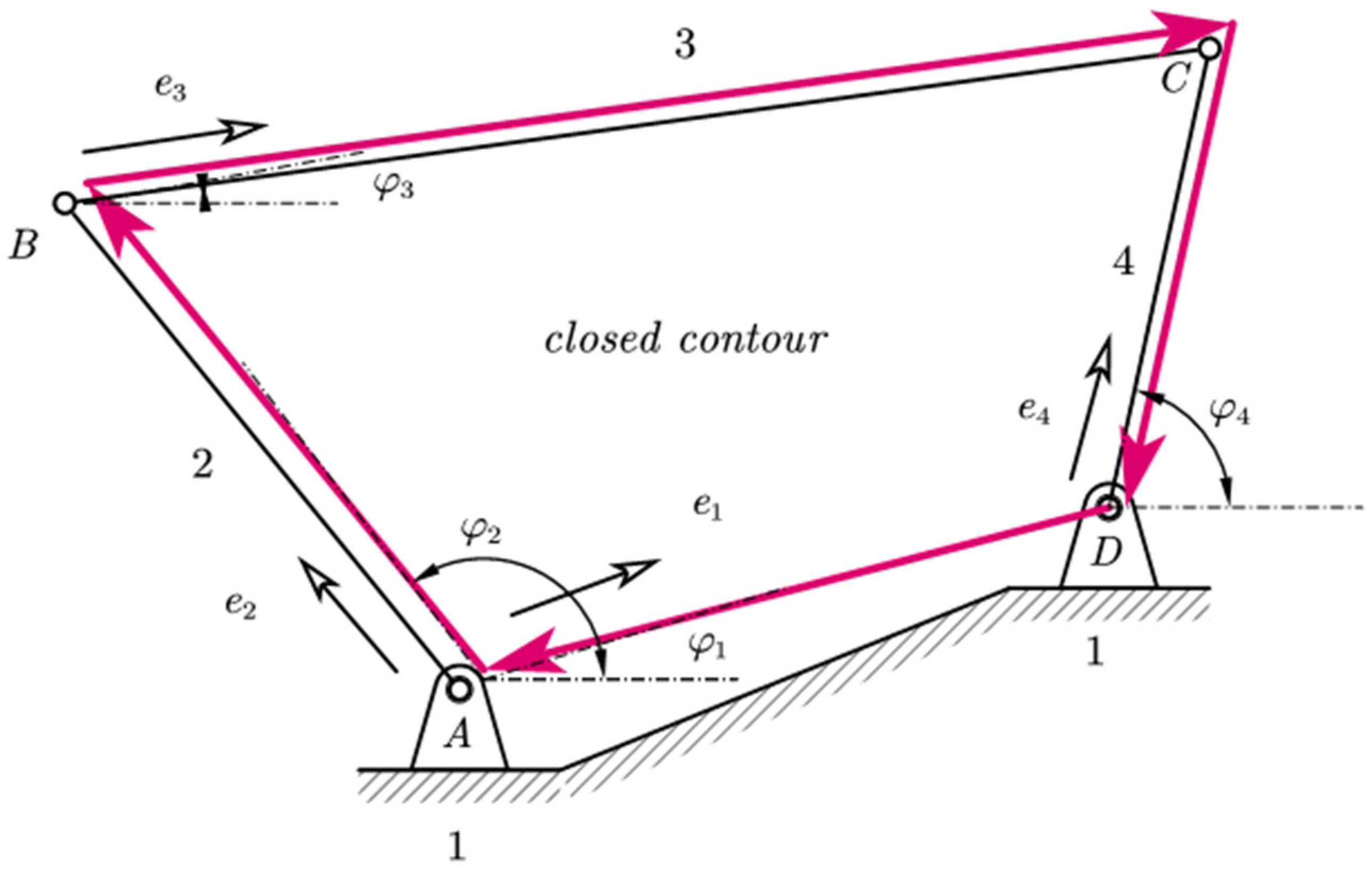
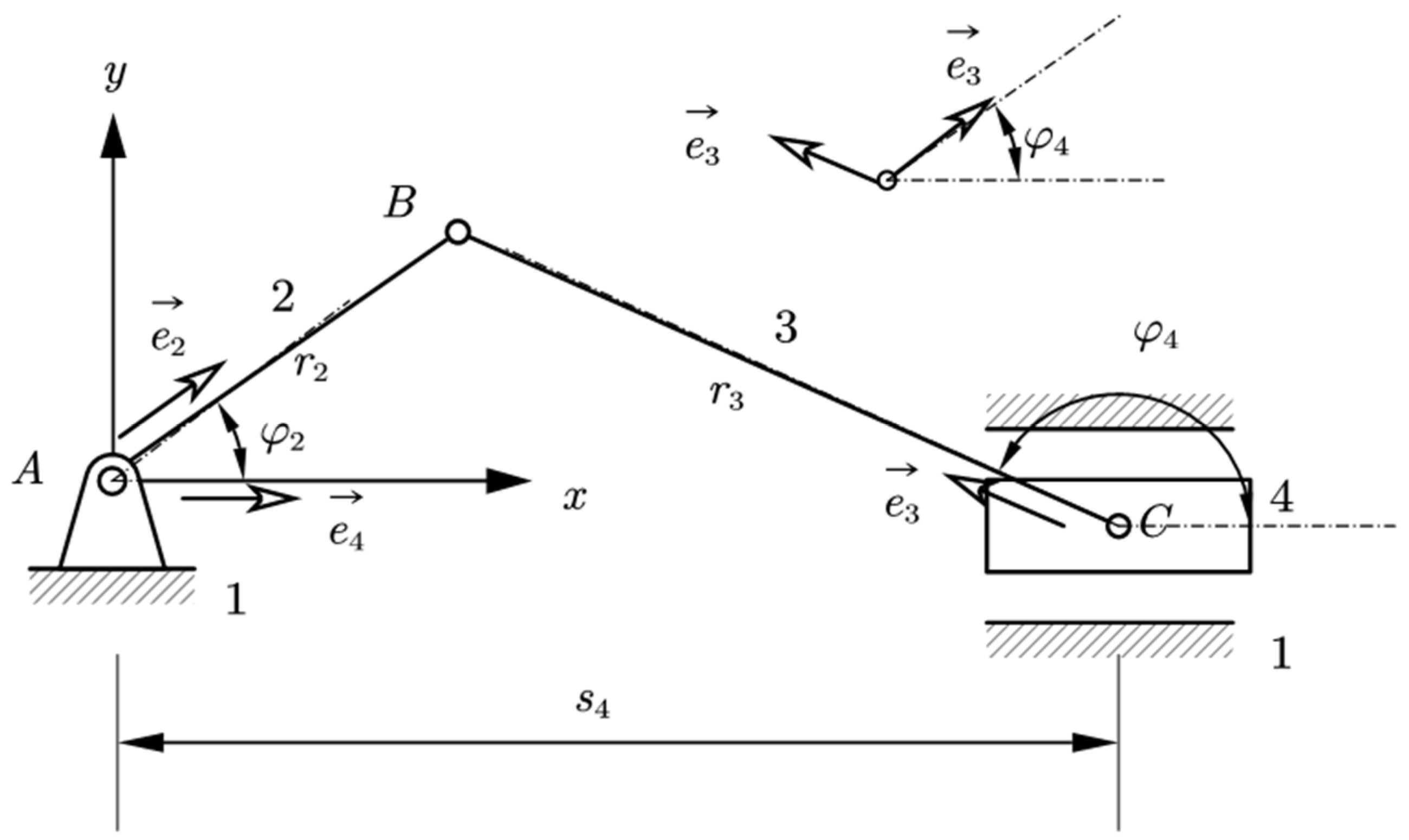
27], the geometric dimensions as well as the kinematic dimensions of the leading link or links, i.e., positions, velocities, and accelerations, are known. All the kinematic magnitudes of the other links forming the Assur groups are required. Let us analyze a 4-bar mechanism with four nodes (
Figure 2). The simplest low-pair joint mechanism consists of 4 links and 4 joints and forms a closed contour [
26].
For the closed contour, the vector equation (Equation (1)) is always true, consisting of vectors located in the links of the mechanism, which form the contour [
25].
This equation can be expressed as Equation (2):
For each unit vector
, we rotate it to form a narrow angle and make its projections on the
and
axes. The projection in
and
of the vector Equation (2) are, respectively, Equations (3) and (4).
So, for planar mechanisms with nodes of the fifth class, the number of contours from which vector polygons are formed will be equal to (Equation (5)).
where
are nodes and
are links of mechanism.
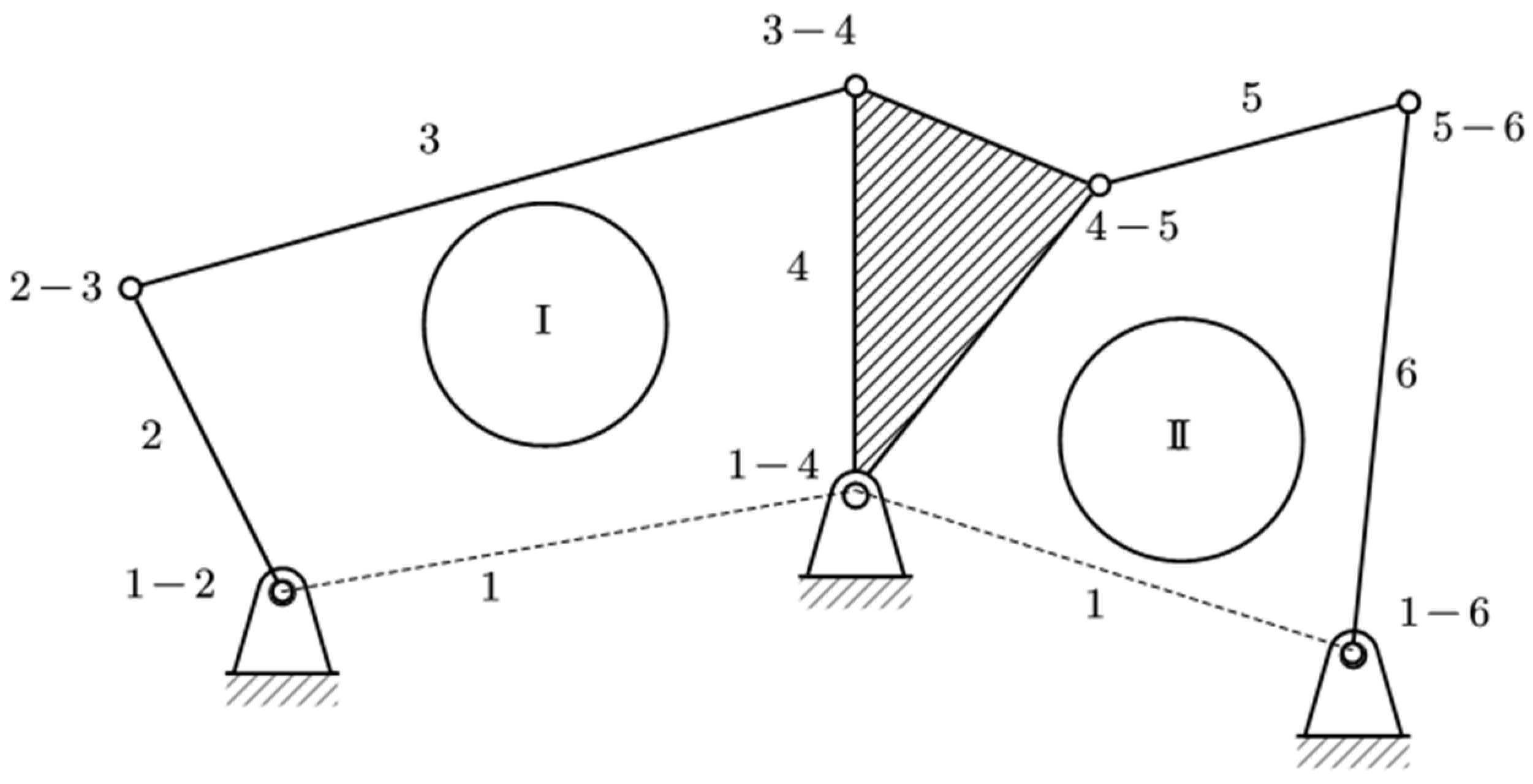
A six-link mechanism (
Figure 3) has two contours and from them result four equations for analysis, which means that as many links of Assur groups we have, we will have as many unknown ones as possible. So, we have
nonlinear equations with
unknowns. These nonlinear equations are almost always solved cyclically [
27].
In the Assur groups, two links are missing, the leader and the base, if the mechanism has a degree of freedom.
So, we can calculate the number of contours as shown in Equation (6).
5. Influence Line on Statically Determined Structures
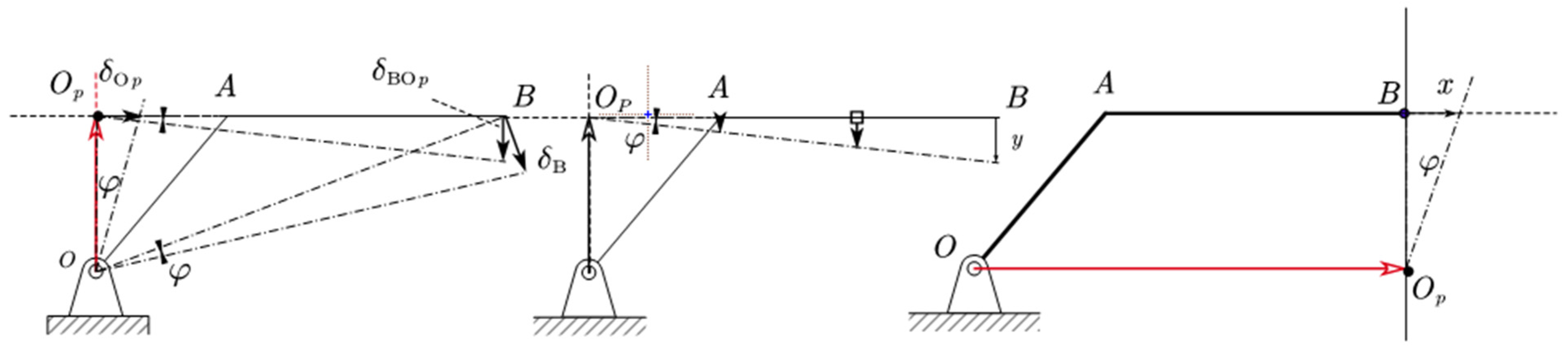
Moving loads in a structure cause changes in reactions, internal forces, and displacements of its points, as shown in
Figure 5 for a simple bar. Since the number 1 has the property that if it is multiplied by any number, it does not change the latter, as well as the fact that the material is linearly elastic, the driving force is accepted as 1 unit, and graphs of the changes in these factors are constructed and placed on the path of movement of the force. The force is assumed to move with almost zero velocity, to eliminate inertial forces, and to use static equations. These graphs are called the influence line of the respective factor [
30,
31]. By employing the principle of virtual displacements to the mechanism illustrated in
Figure 6 [
32], Equation (18) can be expressed as follows, given that the structure consists of only two factors:
where
and
represents the relative motion of disc
with respect to
, which is rotational around section
, since the disc was split into two parts
and
.
Consequently, the line of influence of the factor, i.e., represents the departure from the path of the points of the path during the movement of the force.
The influence line of a certain factor is the same as the departure or “derailment” from the path in the mechanism obtained by the removal of a certain obstacle, caused by a relative movement of “1” unit. A relative displacement of 1 unit is called a discontinuity or assembly error. Let us review the force factors, nodes, and discontinuity 1 unit in turn.
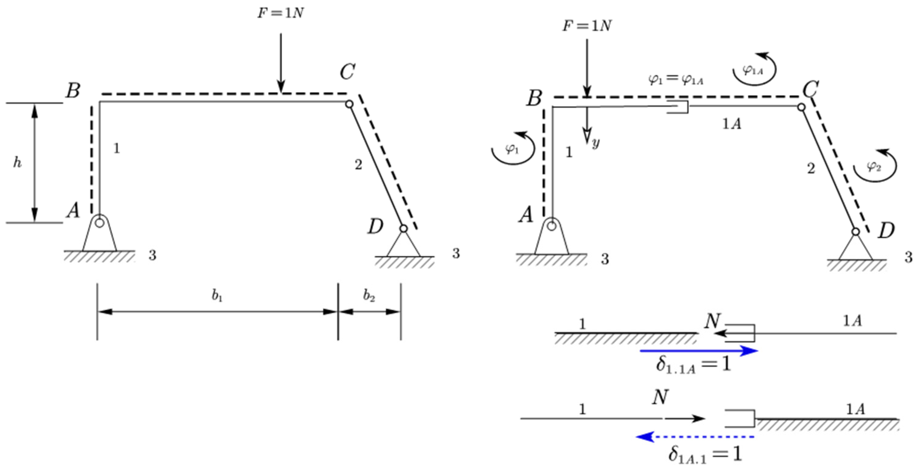
5.1. Influence Line of the Normal Force
For this case as shown in
Figure 7, the solution will be as shown in Equation (19).
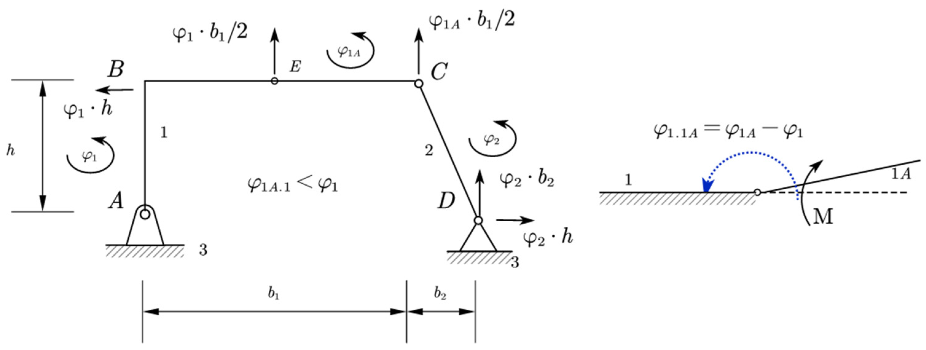
5.2. Influence Line of the Shear Force
The influence line for the shear force is shown in
Figure 8, and the solution will be as in Equation (20).
6. The Geometric Meaning of Jacobians
For the closed contour,
Figure 6, we can write the corresponding vector equation.
Let us take the variation in the above closed contour vector equation (Equation (22)).
More specifically, knowing the virtual rotation angles of the discs we have (Equation (23)), as shown below:
Projecting it along both the horizontal and vertical axes, we derive two equations to find the angles according to
Figure 9. In the general case, we default to the virtual angles to the counter-clockwise sense that also shows with the positive sign [
33].
In the horizontal direction, we have . In the vertical direction, we have .
When the points are located on ground link (not movable), they are stationary and therefore have zero displacements. By introducing the concept of relative motion, we naturally also have carrier motion and can write that .
In this case, we have the carrier movement with the links of the statically undetermined structure and the mechanism only with the relative movement
, the sign depends on the force factor. Internal factors [
34], from the principle of action and counteraction, do not perform work during the carrier movement. These factors do work only during relative motion, equal to one unit by the factor and in the opposite direction to the factor (Equation (24)).
Written in the form of a matrix equation, where one side represents the work in the carrier motion and the other side the work in the relative motion, is given as follows (Equation (25)).
The carrier work matrix also represents the Jacobian, since the first derivatives represent the velocity vector, which is proportional to the displacement [
30]. This is also the geometric meaning of the Jacobian, which represents the matrix of infinitesimal displacements in the carrying motion of the contours, which, for a given structure, is invariant and applies to all internal factors wherever they are located on the contour (
Figure 10).
7. Application of the Jacobian Method
The following
Figure 11 represents, step by step, an application of the Jacobian method to a statically determined structure. The first case is for the internal moment, the second case is for the shear force, and the last is for the normal force [
35,
36,
37].
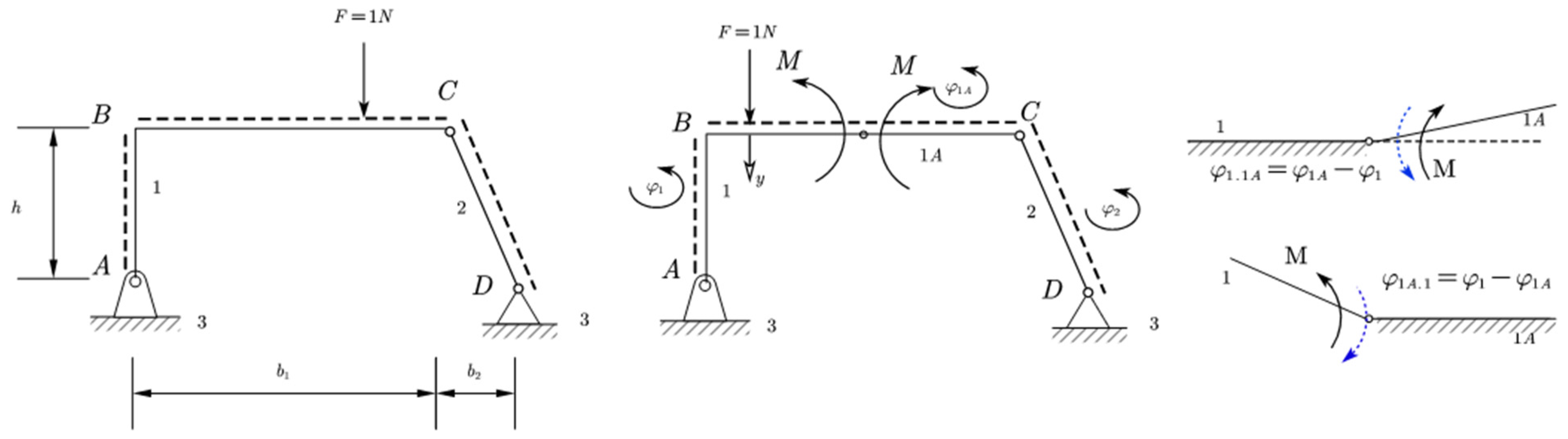
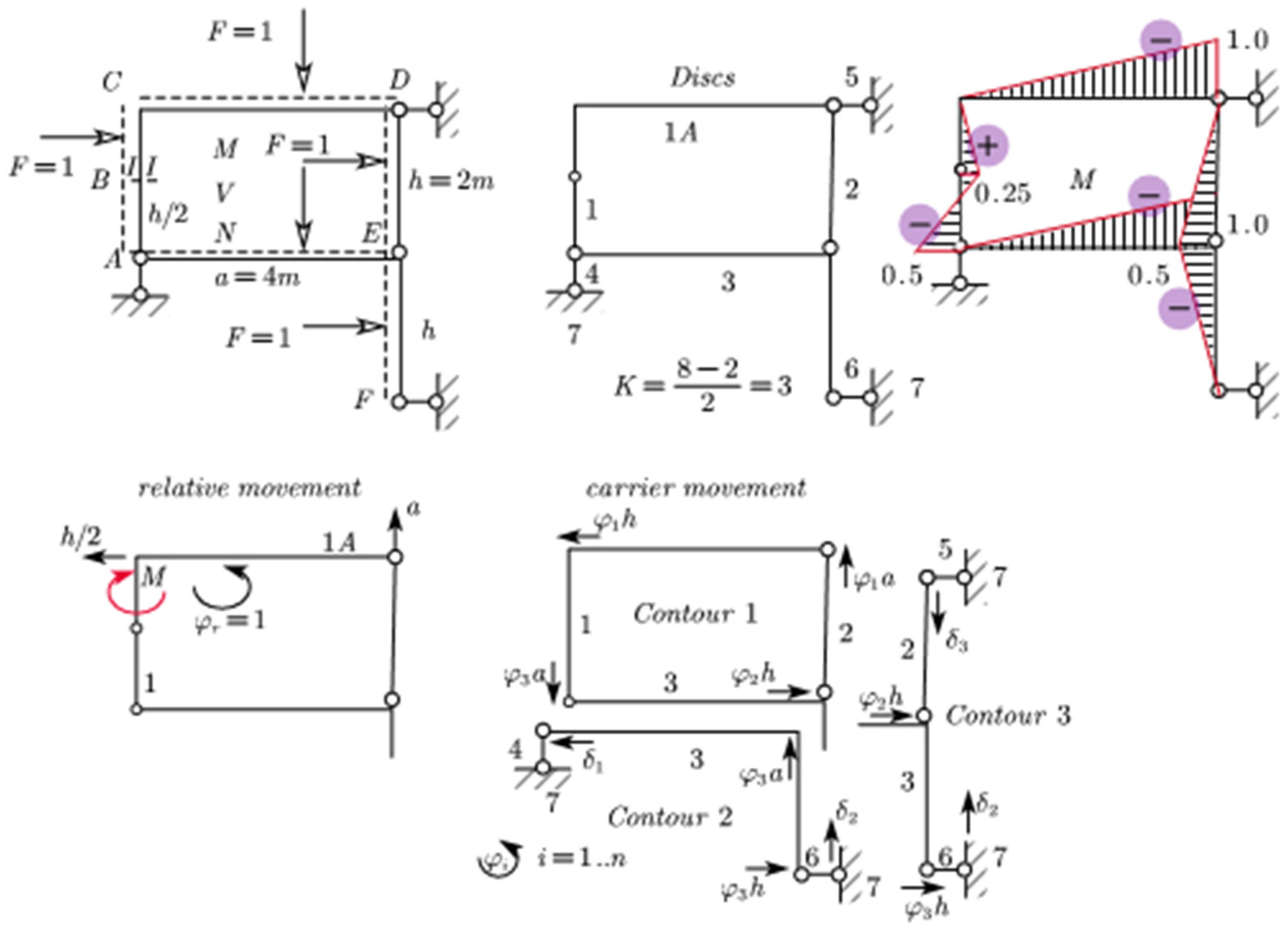
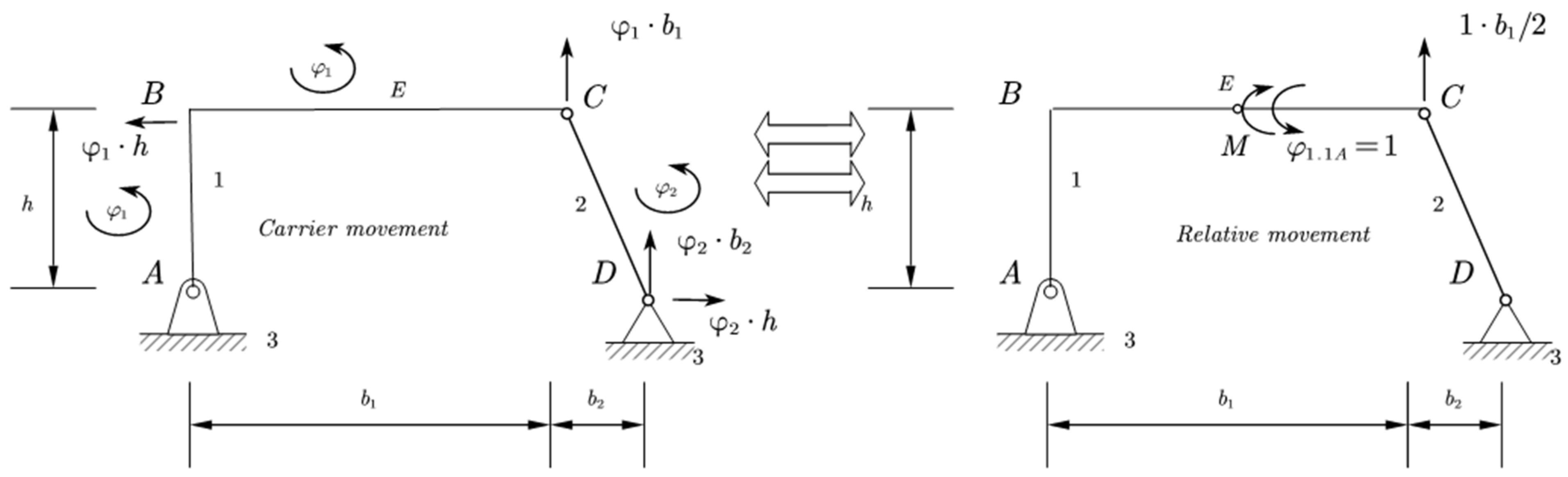
7.1. Application for the Internal Moment
Let us see the application of this method for the internal moment. The steps are shown in
Figure 11.
The Jacobian matrix can be written as shown in Equations (26) and (27).
Relative motion and solution of the system will be:
“Derailment” from the paths in this case will be as in
Table 1.
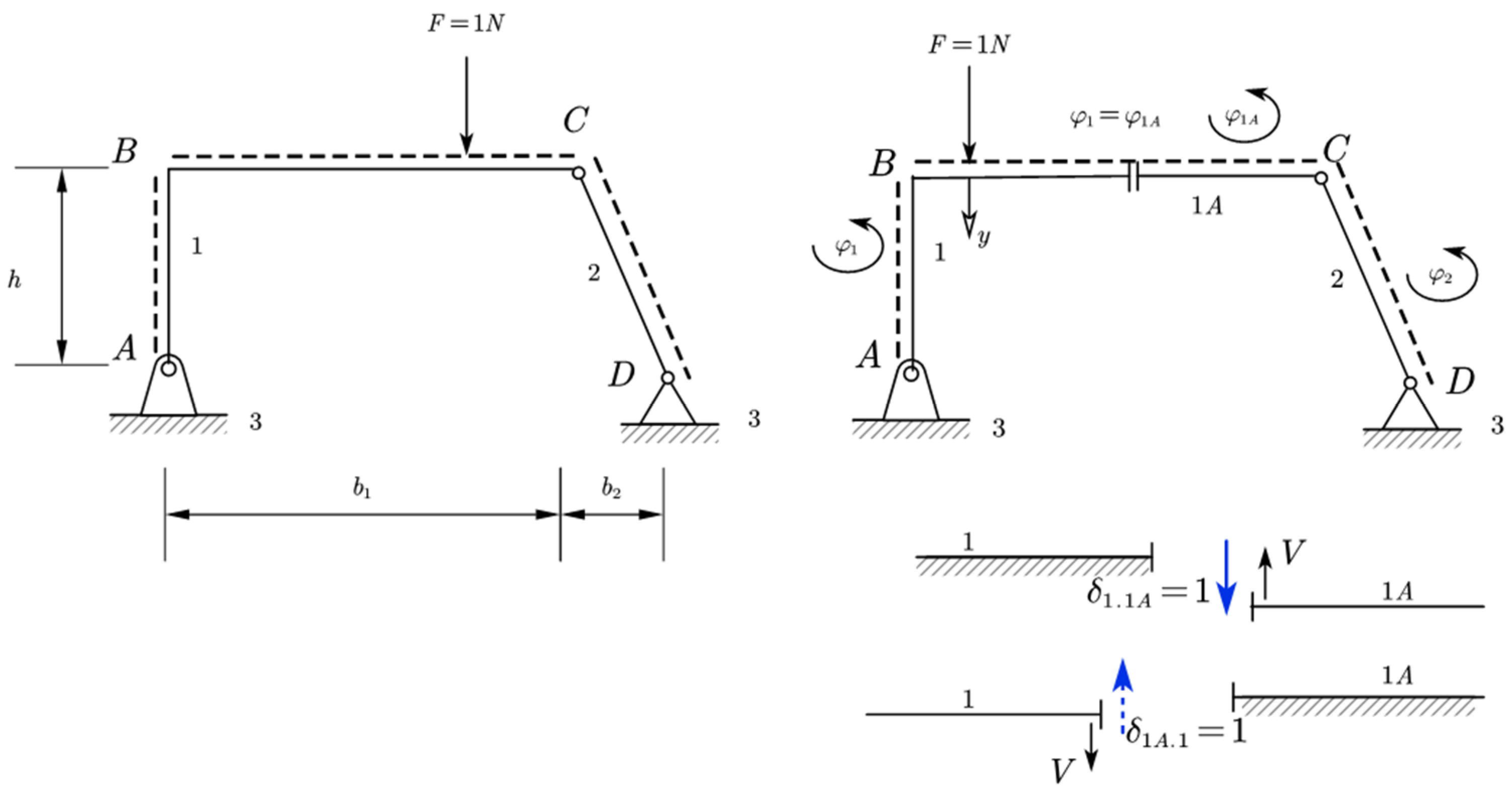
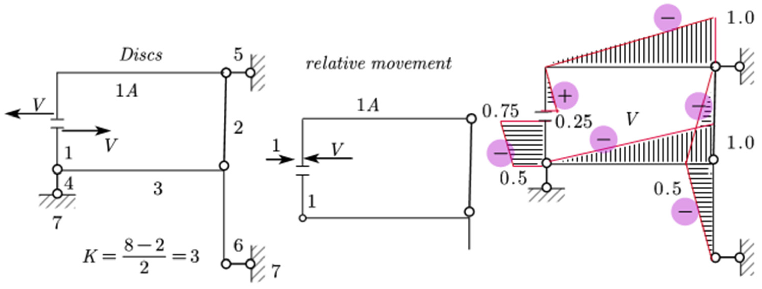
7.2. Application for the Shear Force
For the shear force shown in
Figure 12, the relative motion and solution of the system will be:
So, “derailment” from the paths in this mentioned case will be as in
Table 2.
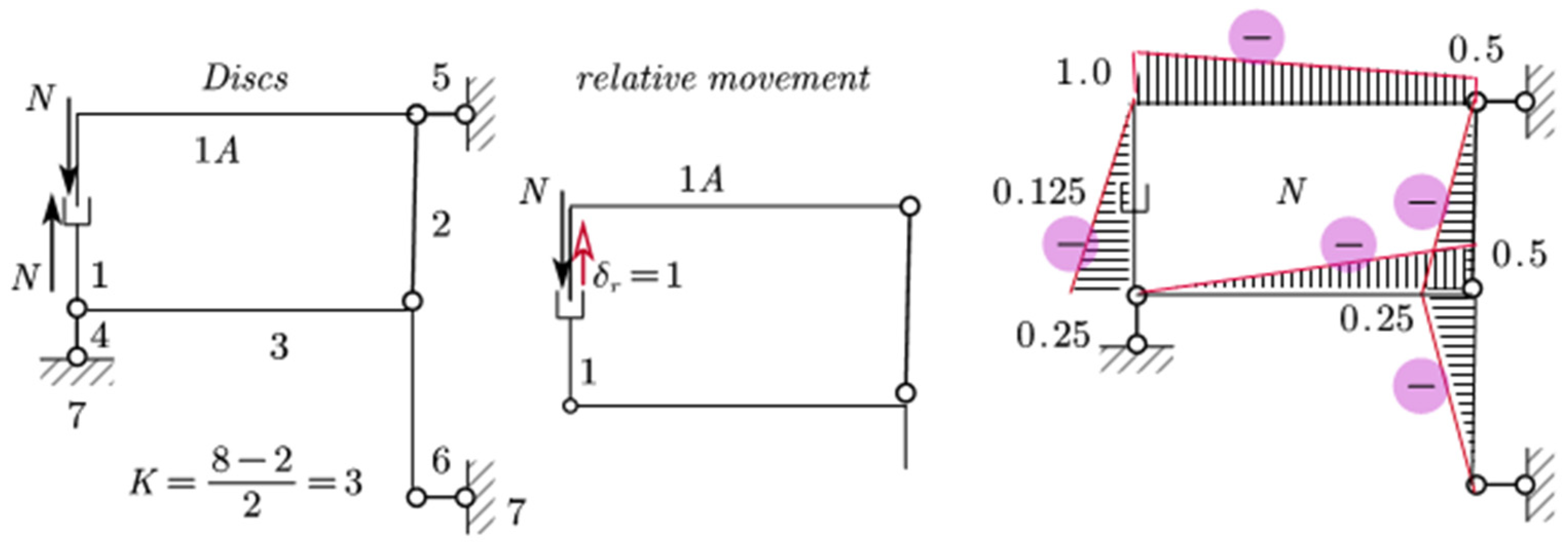
7.3. Application for the Normal Force
For the normal force applications, the case can be shown as
Figure 13.
Relative motion and solution of the system will be:
“Derailment” from the paths in this case will be as in
Table 3.
To examine deeper into the significance of our findings and their broader implications within the fields of structural engineering and applied mechanics there are some aspects to discuss as follows.
Invariance of the Jacobian Matrix: One of the key findings of our study is the invariance of the Jacobian matrix for statically determined structures. This finding underscores the robustness and reliability of the Jacobian matrix as a tool for analyzing and predicting the behavior of such structures under varying load conditions. This invariance property provides engineers and designers with a powerful and consistent means to assess structural responses.
Geometric Interpretation of the Jacobian Matrix: Our work has revealed a geometric interpretation of the Jacobian matrix, shedding light on its tangible significance. It represents a chain of infinitesimal vector displacements forming a closed contour, projected in both the x and y dimensions. This geometric understanding enhances our grasp of the intricate interplay between forces and geometry within statically determined systems. This insight into the geometric nature of the Jacobian matrix has implications far beyond our study, as it enriches the toolbox of structural engineers by offering a more intuitive perspective on structural behavior.
Pre-Construction of the Jacobian Matrix: Our approach introduces the concept of pre-constructing the Jacobian matrix before the actual mechanism is built. This proactive strategy streamlines the analysis process by eliminating constraints considered in the study, paving the way for a systematic and efficient evaluation of influence lines. The pre-construction methodology introduced here holds great potential for accelerating the analysis of statically determined structures, potentially reducing both time and computational resources required for such evaluations.
Loading Characteristics of Mechanisms: Our study has illuminated an intriguing aspect of the mechanisms derived from statically determined structures. These mechanisms experience loading primarily through the relative movement of one unit, typically in the opposite direction or sense from the previously established internal factor. Understanding these loading characteristics is invaluable for engineers and designers, as it provides insights into how forces are distributed and how mechanisms respond to changes in load conditions. This insight could prove pivotal in optimizing the design and performance of various mechanical systems.
Behavior of Discs and Derailments: Our findings have also offered insights into the behavior of discs within the context of statically determined structures. Notably, discs do not extend, and derailment is represented as the rotation of the path around the point of zero derailment. These observations deepen our understanding of the intricate mechanics governing these structures and contribute to a more comprehensive knowledge base in the field of structural engineering.
The invariance and geometric significance of the Jacobian matrix, along with the concept of pre-construction, loading characteristics, and behavior of elements like discs, collectively advance our understanding of structural behavior.
8. Conclusions
In summary, our comprehensive exploration has introduced a groundbreaking method centered on the application of Jacobian contours for evaluating influence lines within statically determined structures. Throughout this paper, we have undertaken a multi-faceted investigation, encompassing various facets of structural analysis.
Our study commenced with the scrutiny of 4-bar mechanisms, followed by the development of an Iterative Solution approach. This iterative process, coupled with the calculation of displacements and velocities via the method of contours, formed the foundational steps in our methodology. We then turned our attention to the examination of influence lines, delving into their implications on statically determined structures, with a specific focus on both normal and shear forces.
Additionally, we have delved deep into the geometric interpretation of Jacobians, revealing their profound significance. This geometric insight has given a new light on the intricate relationships between forces and geometry within statically determined systems.
A notable feature of our method is the pre-construction of the Jacobian matrix, a foundational step taken before the actual mechanism is assembled. This proactive approach has shown the way for a systematic and efficient analysis of influence lines, allowing us to anticipate and understand structural responses with greater precision.
Perhaps one of the most intriguing revelations of our study pertains to the behavior of mechanisms derived from statically determined structures. We have discovered that these mechanisms exclusively experience loading through the relative movement of one unit, which occurs in the opposite direction or sense to previously established internal factors. This insight provides a valuable understanding of the nuanced interplay between forces and movements within these structures.
A key advantage of our method is the proactive pre-construction of the Jacobian matrix before mechanism assembly, which streamlines the process and enables efficient analysis. This forward-thinking approach simplifies structural response predictions, offering engineers and designers a valuable tool to expedite the design process. One of the disadvantages of this method is that while introducing geometric insights, may require engineers and analysts to adapt to a slightly different conceptual framework compared to more traditional methods. This transition, while not impossible, it may necessitate some familiarity with Jacobian matrices and their application in structural analysis.
In conclusion, our innovative utilization of Jacobian contours has provided fresh insights and tools that extend the boundaries of structural engineering. By enhancing our understanding of the Jacobian’s invariance, geometric significance, and pre-construction role, we offer engineers and designers powerful new means to enhance the safety and efficiency of load-bearing structures. These collective findings mark a significant advancement in the field of applied mechanics and structural engineering, lighting the way for more accurate, efficient, and adaptable structural analyses.


