Article

Modal Analysis of Optimized Trapezoidal Stiffened Plates under Lateral Pressure and Uniaxial Compression

1
Institute of Mining and Geotechnical Engineering, University of Miskolc, H-3515 Miskolc, Hungary
2
Institute of Applied Mechanics, University of Miskolc, H-3515 Miskolc, Hungary
*
Author to whom correspondence should be addressed.
Appl. Mech. 2021, 2(4), 681-693; https://doi.org/10.3390/applmech2040039
Submission received: 30 August 2021 / Revised: 15 September 2021 / Accepted: 26 September 2021 / Published: 28 September 2021
(This article belongs to the Special Issue Mechanical Design Technologies for Beam, Plate and Shell Structures)

Abstract

:
This paper deals with the modal analysis of optimized trapezoidal stiffened plates with simple supported conditions on the four edges of the base plate. The main objective of the finite element analysis is to investigate the natural frequencies and mode shapes of some stiffened structures subjected to lateral pressure and uniaxial compression in order to identify any potentially dangerous frequencies and eliminate the failure possibilities. The natural frequencies and mode shapes are important parameters in the design of stiffened plates for dynamic loading conditions. In this study, the numerical analysis is performed for such a design of this kind of welded plates which have already been optimized for lateral pressure and uniaxial compression. The objective function of the optimization to be minimized performed with the Excel Solver program is the cost function which contains material and fabrication costs for Gas Metal Arc Welding (GMAW) welding technology. In this study, the eigenvalue extraction used to calculate the natural frequencies and mode shapes is based on the Lanczos iteration methods using the Abaqus software. The structure is made of two grades of steel, which are described with different yield stress while all other material properties of the steels in the isotropic elastic model remain the same. Drawing the conclusion from finite element analysis, this circumstance greatly affects the result.

1. Introduction

Welded stiffened plates are widely used in various load-carrying structures, e.g., ships, bridges, bunkers, tank roofs, offshore structures and vehicles. They are subject to various loadings, e.g., compression, bending, shear or combined load. The shape of plates can be square rectangular, circular, trapezoidal, etc. They can be stiffened in one or two directions with stiffeners of flat, L, box, trapezoidal or other shapes. From these structural versions, we select here rectangular plates that are uniaxially compressed, laterally pressed and stiffened in the direction of the compressive load.
Several researchers have studied the behaviour of stiffened plates, which remains a widely researched topic. Kim et al. [1] proposed a refined empirical formulation to predict the ultimate strength performance or ultimate limit state of flat-bar type steel stiffened panel under longitudinal compression. De Queiroz et al. [2] performed a structural numerical analysis to estimate the central deflection of thin stiffened plates and simple supported stiffened plates subjected to a transverse and uniformly distributed load, and the influence of parameters such as the number of longitudinal and transverse stiffeners and the ratio between their height and thickness, and searched for the optimal geometrical configuration of for naval and offshore applications by applying the exhaustive search technique and using Ansys software. Li et al. [3] investigated the ultimate strength of welded stiffened plates under the predominant action of axial compression with non-linear finite element analysis using the commercial finite element code Abaqus. Troina et al. [4] developed an approach associating the Constructal Design Method [5] and Exhaustive Search technique, merged in a computational model, validated and then applied with the scope to minimize the central deflections of these plates.
In addition, many studies have been published to reduce the total cost by minimizing the total weight and fabrication cost of the welded stiffened structure. To achieve the lowest costs, many optimization methods have been proposed and developed. Welding is a relatively expensive technology in the fabrication of stiffened plates. It is important to decrease the cost of the whole structure. Therefore, designers use a suitable structural version by comparison of structural solutions.
Structural optimization is a good basis not only for achieving weight and cost savings but also for helping designers select the most suitable structure version. Papers [6,7] elaborated a new optimization method for a totally FRP composite construction in which the single-objective weight optimization was solved by applying the Interior Point Algorithm of the Matlab software, the Generalized Reduced Gradient (GRG) Nonlinear Algorithm of the Excel Solver software, and the Laminator software. The Digimat-HC software solved the numerical models for the optimum structure. Their main contribution was developing a new method for optimizing a totally FRP composite sandwich structure. Zhou et al. [8] studied some distribution laws of the stress mode shapes (SMSs) from the layup and stress component perspectives for the analysis and optimization of dynamic composite laminates in aircraft structures. A study by Guan et al. [9] indicated that the four-node support can be used in a free vibration test to determine the elastic properties of full-sized wood composite panels. Kim et al. [1] studied the ultimate limit state (ULS) behaviour of stiffened panels under longitudinal compression by a non-linear finite element method (NLFEM) using the Ansys software and considering different types of stiffeners mainly being used in shipbuilding, i.e., T-bar, flat-bar and angle-bar.
This paper contains the minimum cost design of longitudinally stiffened plates using strength calculation methods and finite element analysis, which is a powerful technique that is used, among other things, for the dynamic response of structures. Numerous studies have discussed the inclusion and efficiency of the finite element method in the analysis of structures; therefore, the case of stiffened plates is also studied successfully in this way [10]. More detailed descriptions of finite element procedures can be found in [11,12]. Numerical simulation possibilities employ finite element methods for the modal and buckling analysis of plates to investigate the effect of initial geometric imperfection on the load-displacement response. It is worthwhile to mention the use of FEA if there are necessary cutouts in a thin-walled structure as a functional requirement that weaken the affected part of the structures, thus compromising the structure’s integrity, or if the stiffeners are reinforced the structure. Paper [13] is devoted to the natural frequencies of plates with square holes when subjected to in-plane uniaxial, biaxial or shear loading. Jafari et al. [14] introduced the optimal values of effective parameters on the stress distribution around a circular, elliptical and quasi-square cutouts in perforated orthotropic plates under in-plane loadings. In case the plates also are reinforced with stiffeners, paper [15] provides an overview for the buckling and free vibration analysis. Wu et al. [16] investigated the case of rectangular plates subjected to preloads. The vibrational properties of the structures can also be investigated by numerical and experimental modal analysis with dynamic loads. For instance, in paper [17], mechanical vibrations of the IPM motor components were detected and analyzed via a numerical, analytical and experimental investigation. Modal analysis methods can be useful for vibration control to identify the transient natural frequencies and transient modal shapes online and in real-time [18].
In the authors’ previous paper [19], various Young’s moduli were used, and it was assumed that the structural parts (the base plate and ribs) were made of different steel materials. The natural frequencies were investigated, and a linear perturbation analysis for the stiffened plate with flat stiffeners was performed in the commercial software Abaqus [12], where a flat stiffened plate was only uniaxially compressed. Simple, practical design procedures and calculation methods are not available due to the anisotropy of the stiffened plates having longitudinally single-sided, closed stiffeners. Therefore, it is especially worthwhile to use finite element analysis to determine mode shapes. In this study, the numerical investigations on the vibration analysis of trapezoidal stiffened plates under uniaxial compression and lateral pressure are carried out to identify any potentially dangerous frequencies.

2. Designed Constraints

Paper [20] developed the minimum cost design of longitudinally stiffened plates using strength calculation methods. Its results show that the trapezoidal stiffeners are more cost-effective than open section ribs, e.g., the cost savings can reach 40%, although the higher strength steel is 8–10% more expensive. These procedures can be also applied to many other problems in engineering practice; for example, for composite sandwich structures [6,21] and plastic composite sandwich construction in aircraft structures [7].

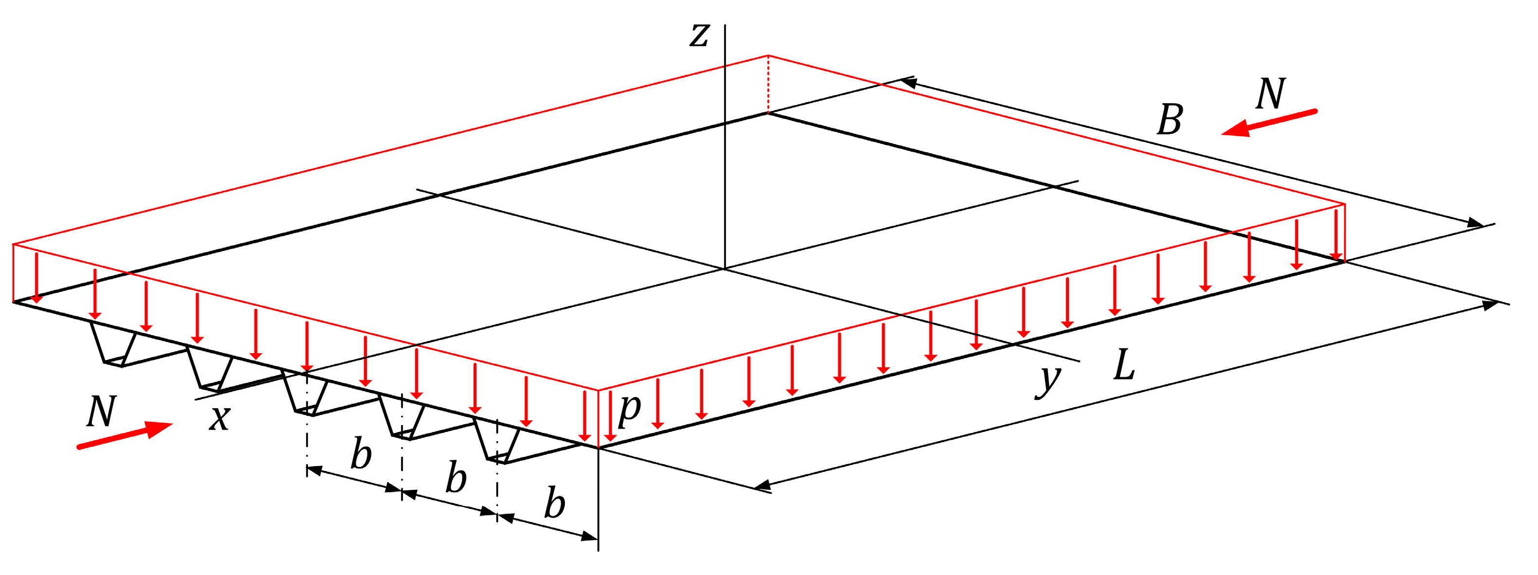
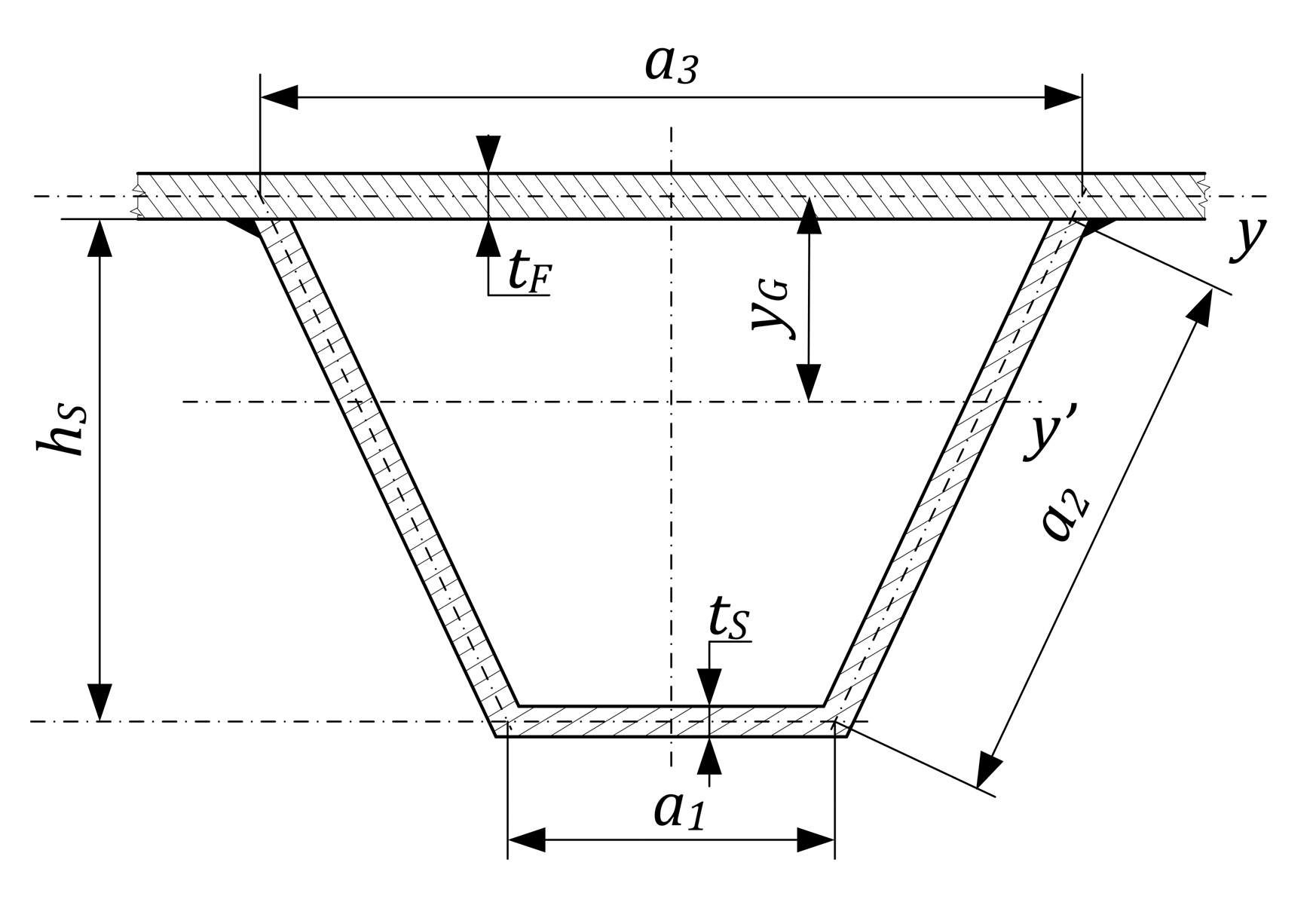
2.1. Calculation of the Deflection Due to Compression and Lateral Pressure

Paper [22] used differential equations of large deflection orthotropic plate theory and the Galerkin method to derive the following cubic equation for elastic deflection of stiffened plate loaded by lateral pressure p and uniaxial compression. They have continued this line for initial deflection in [23].
C 1 A m 3 + C 2 A m 2 + C 3 A m + C 4 = 0 ,
where assuming that the orthotropic model is in a x y plane and provided that the structural reference axes ( x , y , and z ) are parallel to the principal material axes ( x , y , and z ), the following equations are written as:
C 1 = π 2 16 ( E x m 4 B L 3 + E L B 3 ) ,
C 2 = 3 π 2 A o m 16 ( E x m 4 B L 3 + E L B 3 ) ,
C 3 = π 2 A o m 2 8 ( E x m 4 B L 3 + E L B 3 ) + m 2 B L σ x a v + π 2 t F ( D x m 4 B L 3 + 2 H m 2 L B + D y L B 3 ) ,
and
C 4 = A o m m 2 B L σ x a v 16 L B π 4 t F p ,
in which m is the number of half buckling length, B is the width of the base plate under compression, L is the length of the base plate, n = ϕ 1 is the number of ribs, t F and t S are the thicknesses of the base plate and the stiffener, respectively, and the longitudinal Young’s modulus and the transverse modulus are given by
E x = E ( 1 + n A S B t F ) ,     E y = E ,
For given applied compression the uniaxial normal stress is obtained as
σ x a v = N B t F + ( φ 1 ) A s ,
and A o m is according to Equation (16).
The self-weight is taken into account; consequently, the lateral pressure is modified as
p = p 0 + ρ V g B L ,
where ρ is the material density, V is the volume of the structure, p 0 is the uniformly distributed load, and the gravitational acceleration is denoted by g .
The torsional and flexural stiffnesses of the orthotropic plate can be given in a relatively simple form if we introduce the following notations:
D x = E t F 3 12 ( 1 ν x y 2 ) + E t F y G 2 1 ν x y 2 + E I y b ,
D y = E t F 3 12 ( 1 ν x y 2 ) ,
ν x = ν 0.86 E E x ( E t F 3 12 + E t F y G 2 + E I y b ) E t F 3 12 E I y b ( E E x ) 2 ,
ν y = E E x ν x ,
ν x y = ν x ν y ,
H = G x y I t b ,
G x y = E 2 ( 1 + ν x y ) ,
in which ν is the Poisson’s ratio, y G is the distance of the center of gravity which is derived from Equation (37), I y , given by Equation (38), describes the moment of inertia of cross-section containing a stiffener and a base plate strip of width b, and I t , given by Equation (41), is the stiffener torsional moment of inertia.
The deflection due to lateral pressure is calculated as
A o m = 5 q L 4 384 E I y ,     q = p b ,     b = B φ .
The solution of Equation (1) is
A m = C 2 3 C 1 + k 1 + k 2 ,
where
k 1 = Y 2 + Y 2 4 + X 3 27 3 ,
k 2 = Y 2 Y 2 4 + X 3 27 3 ,
X = C 3 C 1 C 2 2 3 C 1 2 ,
and
Y = 2 C 2 3 27 C 1 3 C 2 C 3 3 C 1 2 + C 4 C 1 .

2.2. Deflection Due to the Shrinkage of Longitudinal Welds

The deflection of the stiffened plate due to the longitudinal welds is as follows
f m a x = C L 2 8 w m a x = L 1000 ,
where the curvature for steel is
C = 0.844 × 10 3 Q T y T I y ,
where Q T is the heat input.
y T = y G t F 2
denotes the weld eccentricity. The heat input for stiffeners for the a W weld size is
Q T = 2 × 59.5 a W 2 .

2.3. Calculation of Stress Constraint

The calculation of the stress constraint can include several effects of loads. These can be the following: average compression stress and bending stress caused by deflections due to lateral pressure, compression and the shrinkage of longitudinal welds.
σ m a x = σ x a ν + M I y y G σ U P ,
where σ x a v is according to Equation (7) and
M = N ( A 0 m + A m + f m a x ) σ x a ν + q L 2 8
is the bending moment, in which the magnitude of compression force is denoted by N.
According to [24], the calculation of local buckling stress σ U P of a faceplate strip of width
b 1 = m a x { a 3 ,   b a 3 } .
is calculated taking into account the effect of residual welding stresses and initial imperfections:
σ U P f Y = ( 0.526 λ P ) 0.7       when           λ P 0.526  
σ U P f Y = 1                 when           λ P < 0.526 ,
where
λ P = b 1 t F 4 π 2 E 10.92 f Y = b 1 / t F 56.8 ε .

3. Optimizing Method and Objective Function

The optimization algorithm methods have been inspired by natural or humanmade phenomena to introduce mathematical formulations that can solve problems in different fields of sciences. Specifically, optimization algorithms are used to find the maximum or minimum of a function. They have a wide range of applications in industry [25] and engineering problems such as structures [20]. Developers are more interested in phenomena that could inspire them to develop a new method that can solve new problems or find the best solutions for the existing ones. More descriptions of the optimum design of steel structures are found in [26,27].
In this paper, the Excel Solver program is used to minimize the cost function. This is a multi-objective optimization method in our case. The iterative algorithm is based on Weighted Normalized Method. The optimal design variables are the thicknesses of the base plate ( t F ) and the stiffener ( t S ) and the number of ribs (φ − 1) which are limited in size.
The objective function to be minimized is the cost function. It is defined as the sum of material ( K m ) and fabrication ( K f ) costs
K = K m + K f = k m ρ V + k f ( T 1 + T 2 + T 3 ) ,
where k m and k f are cost factors, ρ is the density, V is the volume of the structure and T i are the fabrication times: T 1 is the time for preparation, tacking and assembly, T 2 is the time of welding and T 3 is the time of additional work such as deslagging, changing electrodes and chipping. The total time for welding is the sum of T 1 , T 2 and T 3 , which is elaborated in [15]. In this paper, we calculated with GMAW welding technology.
The uniaxial compression at two opposite ends of the structure and the lateral pressure p on the base plate act on the stiffened plate as shown in Figure 1. The magnitude of compression force N is 1.974 × 10 7   N as a result of a uniformly distributed static load which can be described as loading over the length B and at the ends of the stiffeners. As shown in Table 1, three different values are employed for lateral pressure p on the base plate, namely 0.02 , 0.01 and 0.005 MPa.
The material is assumed to be isotropic elastic. In our investigation, the stiffened plate is made of two grades of steel, provided that the difference in steel quality is simply meant by yield stress f Y = 235   MPa and f Y = 355   MPa while Young’s modulus of E = 2.1 × 10 5   MPa , Poisson’s ratio of ν = 0.3 and density of ρ = 7.85 × 10 9   t / mm 3   remain the same.
The welded plates studied were designed to have been optimized for loading while the following dimensions of stiffeners are fixed:
a 1 = 90   mm ,             a 3 = 300   mm ,
and the other dimensions of stiffeners in Figure 2 can be obtained from the optimized results of Table 1 applying the formulas below:
ε = 235 f Y ,
a 2 = 38 ε t S   ,
h S = a 2 2 a 3 a 1 2 .
The distance of the centre of gravity of the rib from the y-axis of the mid-plane of the base plate is calculated as follows:
y G = a 1 t S ( h S + t F / 2 ) + 2 a 2 t S ( h S + t F ) / 2 b t F + A S .
The corresponding inertias of the structure from optimized results can be obtained as follows: Section moment of inertia about the y -axis which is parallel to the y -axis at the centre of gravity
I y = b t F 3 12 + b t F y G 2 + a 1 t S ( h S + t F 2 y G ) 2 + 1 6 a 2 3 t S s i n 2 α + 2 a 2 t S ( h S + t F 2 y G ) 2 ,
in which
sin 2 α = 1 ( a 3 a 1 a 2 ) 2
is given from the dimensions in Figure 2, as are the stiffener moment of inertia
I S = a 1 h S 3 t S + 2 3 a 2 3 t S sin 2 α   ;
and torsional moment of inertia
I t = 4 A P 2   b i / t i ,
where
A P = h S a 1 + a 3 2 = 195 h S ,
  b i t i = a 1 + 2 a 2 t S + a 3 t F .
The geometrical data of the base plate are width B = 6000   mm and length L = 4000   mm . The stiffeners are welded to the base plate with fillet welds to reinforce the plate. The numerical results for uniaxial compression and lateral pressure are summarized in Table 1, in which the columns contain the optimized main geometrical data and the optimised cost results. These results were used for the further modal analysis study.
The result shows that the number of stiffeners φ – 1 decreases if the lateral pressure is increased, but φ – 1 increases if the yield stress of the material is increased.

4. Modal Analysis

The eigenvalue extraction to calculate the natural frequencies and the corresponding mode shapes is based on the subspace or Lanczos iteration methods described in [11], which are used to perform modal frequency response analysis or to investigate the eigenvalue for buckling prediction, and are applied to extract eigenvalues i.e., natural frequencies. Two analysis steps are used for natural frequencies belonging to the trapezoidal stiffened plate subjected to uniaxial compression and lateral pressure. At the first step, the applied loads and geometric nonlinearity were considered so that at the second step, the load stiffness is determined at the end of the first general analysis step and can be included in the eigenvalue extraction. To investigate the natural frequencies, a linear perturbation analysis for the stiffened plate with trapezoidal stiffeners is performed with these steps, using the commercial software Abaqus according to the model shown in Figure 3.

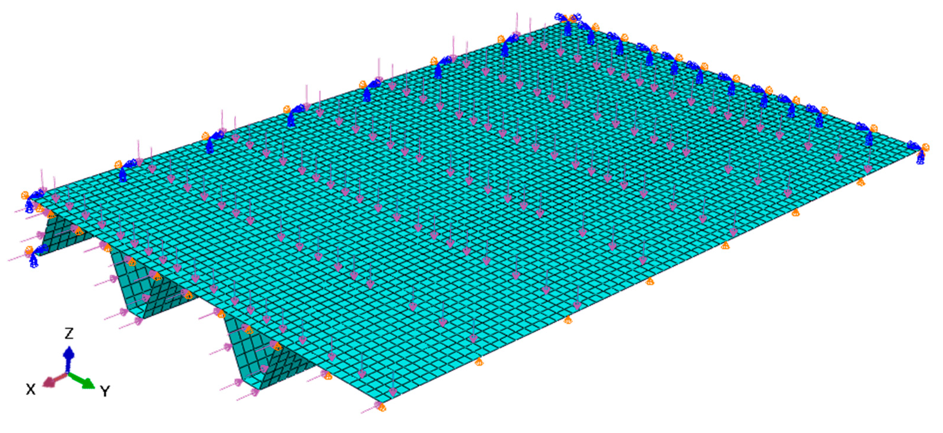
4.1. FE Model Description

The uniform thickness base plate is reinforced by some trapezoidal-shaped stiffeners and simple support conditions are subjected on all the edges (SSSS). As described in Section 3, the stiffener number and geometry were optimized before the FE analysis. Figure 1 is depicted, the side lengths of the plate parallel to the x -axis and y -axis are denoted by L and B , respectively.
Using the advantage of symmetry in geometry and loading, only one-quarter of the plate with boundary conditions is modelled in the FEA. The displacement boundary conditions on the FE model are as follows: Symmetry along the x -axis, for which u y = ϕ x = ϕ z = 0 is required; symmetry along the y -axis, which requires u x = ϕ y = ϕ z = 0 ; simple is prescribed support on the edge at x = ± L / 2 according to u z = ϕ x = 0 and at the edge of y = ± B / 2 according to u z = ϕ y = 0 . Let u x , u y , and u z denote the displacements of a point in the mid-plane of the trapezoidal stiffened plate along the x , y , and z directions, respectively and ϕ x , ϕ y , and ϕ z are the rotations of the normal to the mid-plane at the same point of the structure (see in Figure 3).
The finite element method, which is a popular numerical technique, is used to numerically solve differential equations arising in engineering and modelling problems such as modal analysis problems [10,19]. The main concept of this technique is that the geometry of structure subdivides into non-overlapping small parts, so-called finite elements, which are implemented by the construction of a mesh. The conventional element types possess simple shaped geometry with well-defined stress displacement relationships. Due to the design, stress accumulation occurs at the supports along the side with length B, where the base plate meets the stiffeners, and therefore the mesh destiny in the FE model locally significantly affects the maximum stress values there. At the first step of modal analysis for the preload case, the applied loads and geometric nonlinearity were considered so that the best choice is the first-order element. Thus, the sufficiently refined mesh needs to ensure that the results from simulations are adequate. Accordingly, the trapezoidal stiffened plate is meshed into finite elements, which are four-node reduced integration shell elements (S4R in Abaqus), see details in [11,12]. The approximate global size is specified as 40 mm, as shown in Figure 3.

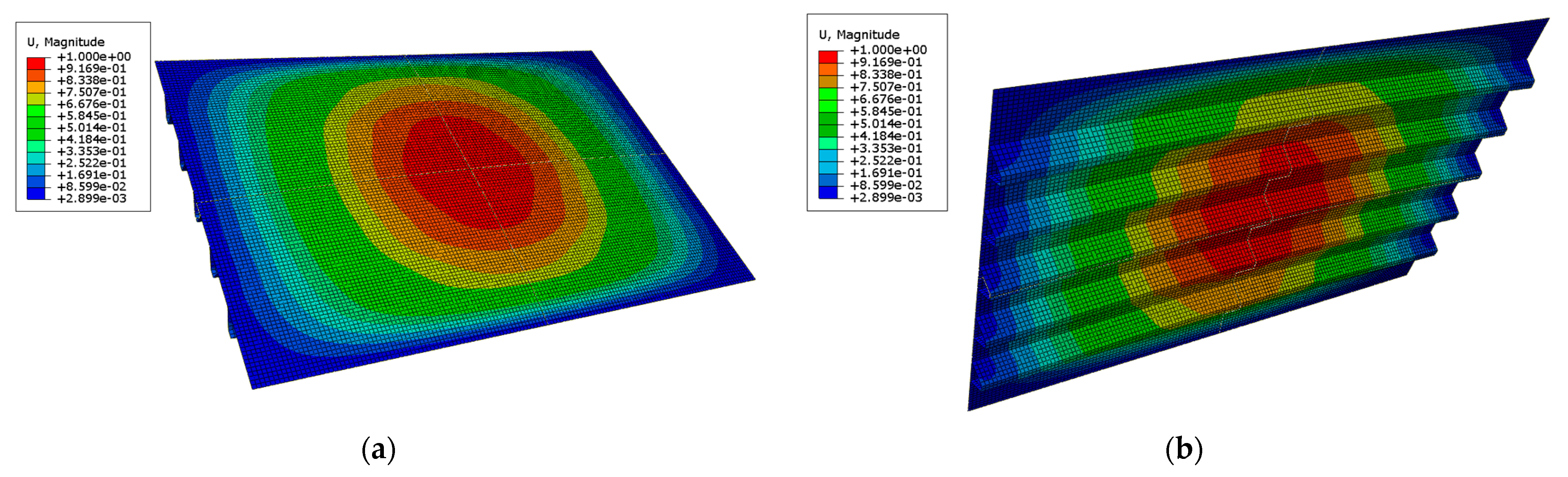
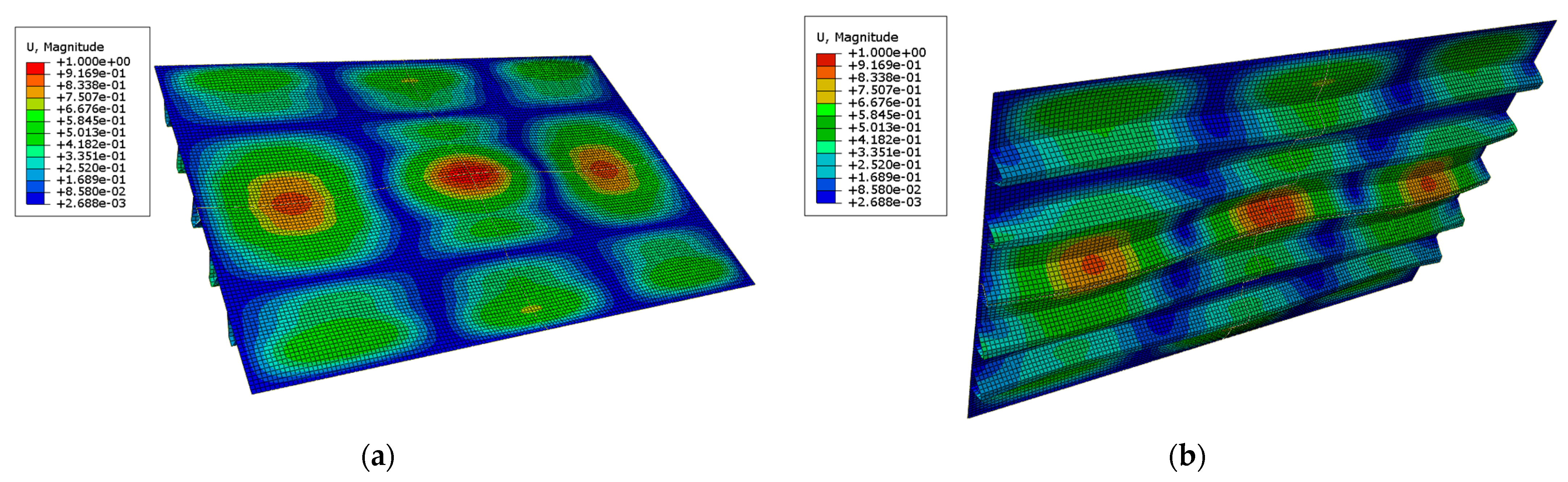
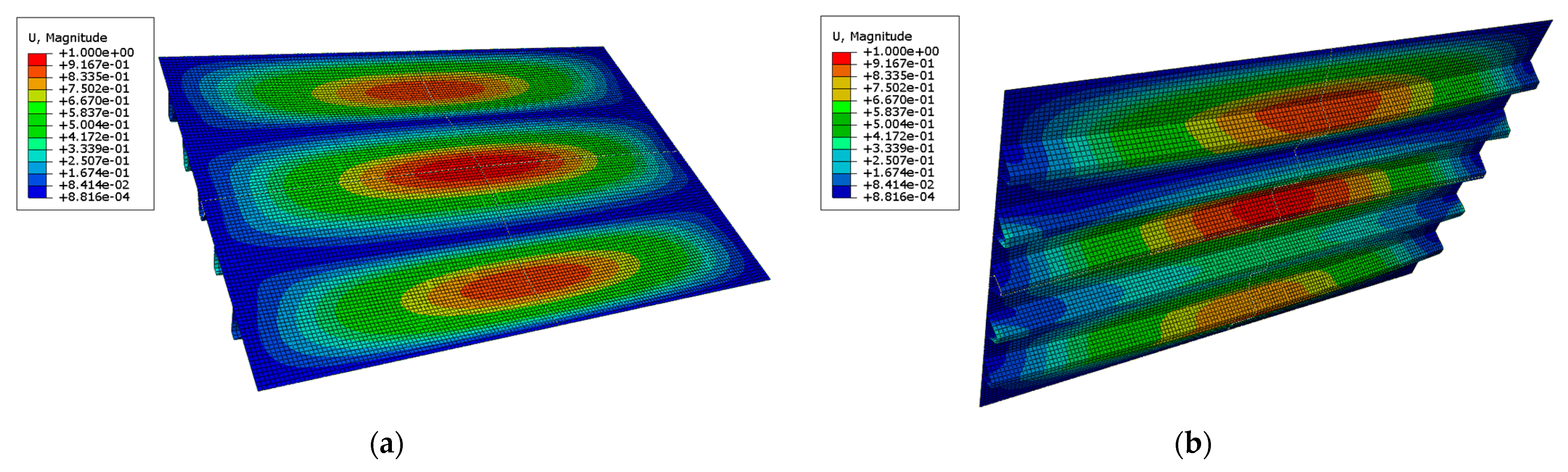
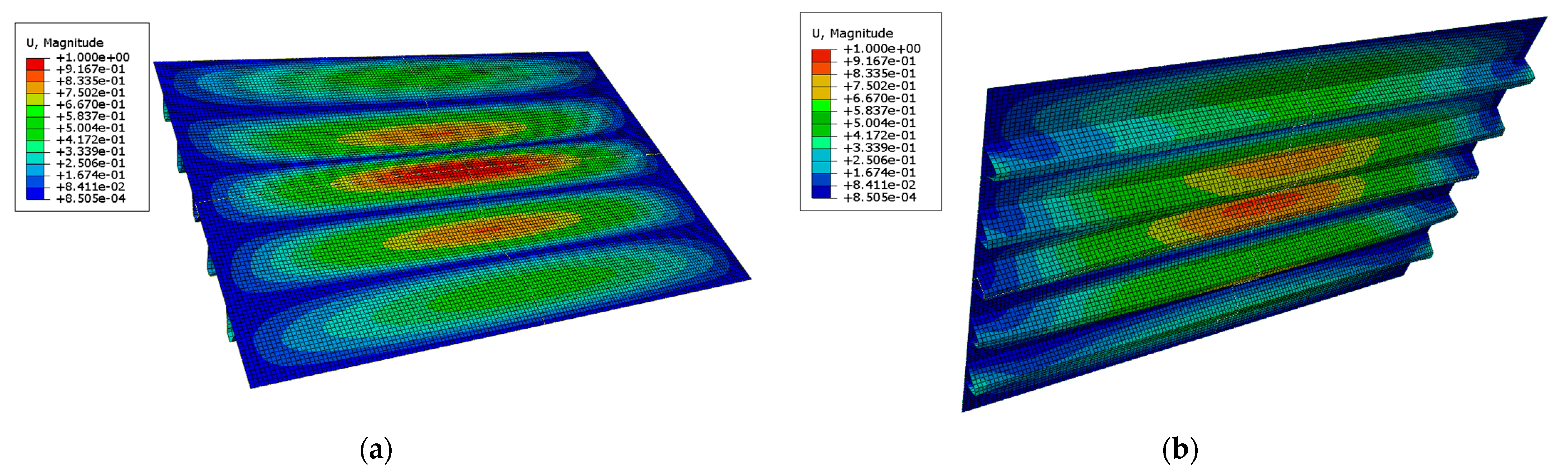
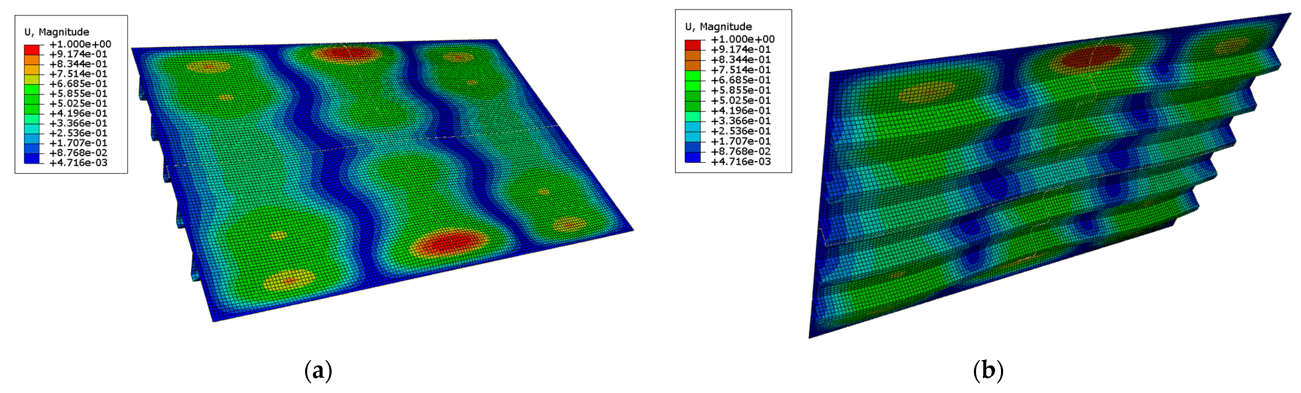
4.2. Modal Analysis Results

The numerical results of the FE analysis for natural frequencies are summarized in Table 2, which contains the first six natural frequencies from No. 1 to No. 6. in order to identify any potentially dangerous frequencies.
In the optimized case 6, the first six mode shapes of the stiffened plate are depicted in Figure 4, Figure 5, Figure 6, Figure 7, Figure 8 and Figure 9. The mode shapes for the other five cases of Table 2 are not shown separately here.
The layout and the number of trapezoid stiffeners can have an important influence on the dynamic response of the stiffened plates. The first natural frequencies show significant difference only at lateral pressure p = 0.005   MPa and p = 0.01   MPa so that the optimized structures of yield stress f Y = 235   MPa and f Y = 355   MPa influence the frequencies of the structures made based on the optimized results in Table 1. According to Table 2, the reduction in the first natural frequencies no longer occurs at lateral pressure p = 0.02   MPa if the grade of steel changes.
Comparing the first natural frequencies in Table 2 with the simulation results without loading, the rate of reduction is between 15 % and 40 % , and the first mode shapes are also similar to Figure 4a,b as expected. The same conclusions can be derived from [19]. Practice shows that the natural frequencies as numerical results of FEA are in good agreement with the experimental results. We can conclude that the plates become stiffer with more stiffeners, and the maximum displacement decreases so that the stiffeners can have a significant effect on global displacement.

5. Conclusions

The result of optimization for different manufacturing costs leads to structures with different geometry. The increased yield stress leads to a thickening of the base plate and a decrease in the number of ribs. From the optimization process and the finite element analyses carried out to examine the behaviour of trapezoidal stiffened plates under uniaxial compression and lateral pressure, the following conclusions can be drawn: that (i) the number of stiffeners φ – 1 decreases if the lateral pressure is increased, but φ − 1 increases if the yield stress of the material is increased, (ii) the eigenfrequencies show a significant decrease based on our finite element analysis if the trapezoidal stiffened welded plates are subjected to given loadings, (iii) the structure can be made of two grades of steel, which are described with different yield stress while all other material properties in the isotropic elastic model remain the same, then this condition is greatly influencing the results, and (iv) the influence of initial geometric imperfections allowed by designed constraints on frequencies is less significant, which is similar to the results in [19]. Therefore, it is important to know that the structures are properly designed, made from proper materials, and constructed considering loading during their lifespan. The FE analysis has provided the natural frequencies and shape modes so that the dynamic behaviour of the stiffened plates can be further investigated by mode superposition analysis.

Author Contributions

Conceptualization, Z.V. and S.S.; methodology, Z.V. and S.S.; software, S.S.; formal analysis, Z.V. and S.S.; writing—original draft preparation, Z.V. and S.S.; writing—review and editing, Z.V. and S.S.; visualization, Z.V. and S.S. Both authors have read and agreed to the published version of the manuscript.

Funding

This research received no external funding.

Institutional Review Board Statement

Not applicable.

Informed Consent Statement

Not applicable.

Data Availability Statement

Not applicable.

Conflicts of Interest

The authors declare no conflict of interest.

References

  1. Kim, D.K.; Yu, S.Y.; Lim, H.L.; Cho, N.-K. Ultimate Compressive Strength of Stiffened Panel: An Empirical Formulation for Flat-Bar Type. J. Mar. Sci. Eng. 2020, 8, 605. [Google Scholar] [CrossRef]
  2. De Queiroz, J.P.T.P.; Cunha, M.L.; Pavlovic, A.; Rocha, L.A.O.; Dos Santos, E.D.; Troina, G.d.S.; Isoldi, L.A. Geometric Evaluation of Stiffened Steel Plates Subjected to Transverse Loading for Naval and Offshore Applications. J. Mar. Sci. Eng. 2019, 7, 7. [Google Scholar] [CrossRef] [Green Version]
  3. Li, C.; Dong, S.; Wang, T.; Xu, W.; Zhou, X. Numerical Investigation on Ultimate Compressive Strength of Welded Stiffened Plates Built by Steel Grades of S235–S390. Appl. Sci. 2019, 9, 2088. [Google Scholar] [CrossRef] [Green Version]
  4. Troina, G.; Cunha, M.; Pinto, V.; Rocha, L.; dos Santos, E.; Fragassa, C.; Isoldi, L. Computational Modeling and Constructal Design Theory Applied to the Geometric Optimization of Thin Steel Plates with Stiffeners Subjected to Uniform Transverse Load. Metals 2020, 10, 220. [Google Scholar] [CrossRef] [Green Version]
  5. Reis Amaral, R.; Troina, G.; Fragassa, C.; Pavlovic, A.; Cunha, M.; Rocha, L.; dos Santos, E.; Isoldi, L. Constructal design method dealing with stiffened plates and symmetry boundaries. Theor. Appl. Mech. Lett. 2020, 10, 366–376. [Google Scholar] [CrossRef]
  6. Al-Fatlawi, A.; Jármai, K.; Kovács, G. Optimal design of a fiber reinforced plastic composite sandwich structure for the base plate of aircraft pallets in order to reduce weight. Polymers 2021, 13, 834. [Google Scholar] [CrossRef] [PubMed]
  7. Al-Fatlawi, A.; Jármai, K.; Kovács, G. Optimization of a Totally Fiber-Reinforced Plastic Composite Sandwich Construction of Helicopter Floor for Weight Saving, Fuel Saving and Higher Safety. Polymers 2021, 13, 2735. [Google Scholar] [CrossRef]
  8. Zhou, Y.; Sun, Y.; Zeng, W. A Numerical Investigation on Stress Modal Analysis of Composite Laminated Thin Plates. Aerospace 2021, 8, 63. [Google Scholar] [CrossRef]
  9. Guan, C.; Zhang, H.; Wang, X.; Miao, H.; Zhou, L.; Liu, F. Experimental and Theoretical Modal Analysis of Full-Sized Wood Composite Panels Supported on Four Nodes. Materials 2017, 10, 683. [Google Scholar] [CrossRef] [Green Version]
  10. Jafarpour, S.; Khedmati, M.; Azkat, S. Vibration analysis of stiffened plates using Finite Element Method. Lat. Am. J. Solids Struct. 2011, 9, 1–20. [Google Scholar]
  11. Bathe, K.J. Finite Element Procedures; Prentice-Hall Inc.: Englewood Cliffs, NJ, USA, 1996. [Google Scholar]
  12. Abaqus 6.13 Online Documentation; Dassault Systems. 2015. Available online: http://130.149.89.49:2080/v6.13/index.html (accessed on 9 September 2021).
  13. Sabir, A.B.; Davies, G.T. Natural frequencies of plates with square holes when subjected to in-plane uniaxial, biaxial or shear loading. Thin-Walled Struct. 1997, 28, 321–335. [Google Scholar] [CrossRef]
  14. Jafari, M.; Hoseyni, S.A.M.; Altenbach, H.; Craciun, E.-M. Optimum Design of Infinite Perforated Orthotropic and Isotropic Plates. Mathematics 2020, 8, 569. [Google Scholar] [CrossRef] [Green Version]
  15. Vörös, G.M. Buckling and free vibration analysis of stiffened panels. Thin-Walled Struct. 2009, 47, 382–390. [Google Scholar] [CrossRef]
  16. Wu, Q.; Gao, H.; Zhang, Y.; Chen, L. Dynamical analysis of a thin-walled rectangular plate with preload force. J. Vibroeng. 2017, 19, 5735–5745. [Google Scholar] [CrossRef]
  17. Čorović, S.; Miljavec, D. Modal Analysis and Rotor-Dynamics of an Interior Permanent Magnet Synchronous Motor: An Experimental and Theoretical Study. Appl. Sci. 2020, 10, 5881. [Google Scholar] [CrossRef]
  18. Wang, C.; Huang, H.; Lai, X.; Chen, J. A New Online Operational Modal Analysis Method for Vibration Control for Linear Time-Varying Structure. Appl. Sci. 2020, 10, 48. [Google Scholar] [CrossRef] [Green Version]
  19. Szirbik, S.; Virág, Z. Finite element analysis of an optimized hybrid stiffened plate. MATEC Web Conf. 2021, 342, 06003. [Google Scholar] [CrossRef]
  20. Virág, Z.; Jármai, K. Optimum design of stiffened plates for static or dynamic loadings using different ribs. Struct. Eng. Mech. 2020, 74, 255–266. [Google Scholar]
  21. Kovács, G.; Farkas, J. Optimal design of a composite sandwich structure. Sci. Eng. Compos. Mater. 2016, 23, 237–243. [Google Scholar] [CrossRef]
  22. Paik, J.K.; Thayamballi, A.K.; Kim, B.J. Large deflection orthotropic plate approach to develop ultimate strength formulations for stiffened panels under combined biaxial compression/tension and lateral pressure. Thin-Walled Struct. 2001, 39, 215–246. [Google Scholar] [CrossRef]
  23. Kim, D.K.; Poh, B.Y.; Lee, J.R.; Paik, J.K. Ultimate strength of initially deflected plate under longitudinal compression: Part I = An advanced empirical formulation. Struct. Eng. Mech. 2018, 68, 247–259. [Google Scholar]
  24. Mikami, I.; Niwa, K. Ultimate compressive strength of orthogonally stiffened steel plates. J. Struct. Eng. ASCE 1996, 122, 674–682. [Google Scholar] [CrossRef]
  25. Ghafiland, H.N.; Jármai, K. Research and application of industrial robot manipulators in vehicle and automotive engineering, a survey. In Vehicle and Automotive Engineering 2; Lecture Notes in Mechanical Engineering; Springer: Cham, Switzerland, 2018; pp. 611–623. [Google Scholar]
  26. Farkas, J.; Jármai, K. Analysis and Optimum Design of Metal Structures; Balkema Publishers: Rotterdam, The Netherlands, 1997. [Google Scholar]
  27. Farkas, J.; Jármai, K. Optimum Design of Steel Structures; Springer: Berlin/Heidelberg, Germany, 2013. [Google Scholar]
Figure 1. Design of trapezoidal stiffened plate loaded by uniaxial compression and lateral pressure.
Applmech 02 00039 g001
Figure 2. Dimensions of a trapezoidal stiffener.
Applmech 02 00039 g002
Figure 3. A shell model of one-quarter of the structure with its associated boundary conditions for case 6 of Table 1, also taking advantage of the symmetry.
Applmech 02 00039 g003
Figure 4. The first mode shape of the trapezoidal stiffened plate for case 6 of Table 2: (a) Mode 1 in top view; (b) Mode 1 in the bottom view from the side of the stiffeners.
Applmech 02 00039 g004
Figure 5. The second mode shape of the trapezoidal stiffened plate for case 6 of Table 2: (a) Mode 2 in top view; (b) Mode 2 in the bottom view from the side of the stiffeners.
Applmech 02 00039 g005
Figure 6. The third mode shape of the trapezoidal stiffened plate for case 6 of Table 2: (a) Mode 3 in top view; (b) Mode 3 in the bottom view from the side of the stiffeners.
Applmech 02 00039 g006
Figure 7. The fourth mode shape of the trapezoidal stiffened plate for case 6 of Table 2: (a) Mode 4 in top view; (b) Mode 4 in the bottom view from the side of the stiffeners.
Applmech 02 00039 g007
Figure 8. The fifth mode shape of the trapezoidal stiffened plate for case 6 of Table 2: (a) Mode 5 in top view; (b) Mode 5 in the bottom view from the side of the stiffeners.
Applmech 02 00039 g008
Figure 9. The sixth mode shape of the trapezoidal stiffened plate for case 6 of Table 2: (a) Mode 6 in top view; (b) Mode 6 in the bottom view from the side of the stiffeners.
Applmech 02 00039 g009
Table 1. Optimum dimensions for trapezoidal stiffener at three different lateral pressures ( p ) and constant uniaxial compression ( N = 1.974 × 10 7   N ) in case of two yield stresses ( f Y ) and k m / k f = 1.5   the cost minima.
No.p
[MPa]
f Y
[MPa]
t F
[mm]
t S
[mm]
φ 1
[-]
b
[mm]
K / k m   [ kg ]
k m / k f = 0   k m / k f = 1.5  
1.0.022352393100053176437
2.0.012352383100051226132
3.0.0052352283100049345932
4.0.023551710480049916431
5.0.013551885666.6747005845
6.0.0053551585666.6743205621
Table 2. Comparison of natural frequencies [rad/s] of the first six mode shapes according to the optimized 6 cases taken from Table 1.
No.Mode Sequence Number
123456
1.116.39253.72553.46629.09746.49844.18
2.88.870239.44555.24601.75733.92772.18
3.88.026231.55534.53581.81694.87766.37
4.117.05235.98578.32760.09785.89862.40
5.64.490212.70574.14674.46773.65851.75
6.72.286209.47406.64753.10792.69865.22
Publisher’s Note: MDPI stays neutral with regard to jurisdictional claims in published maps and institutional affiliations.

