Article

Experimental Analysis of Fractured Human Bones: Brief Review and New Approaches

by
Ioan Száva
1,
Iosif Șamotă
2,
Teofil-Florin Gălățanu
3,*,
Dániel-Tamás Száva
4 and
Ildikó-Renáta Száva
3
1
Department of Mechanical Engineering, Transilvania University of Brasov, 500152 Brasov, Romania
2
Department of Fundamental Disciplines and Clinical Prevention, Faculty of Medicine, Transilvania University of Brasov, 500152 Brasov, Romania
3
Department of Civil Engineering, Transilvania University of Brasov, 500152 Brasov, Romania
4
Faculty of Medicine, George Emil Palade University of Medicine, Pharmacy, Science and Technology of Targu Mures, 540142 Targu Mures, Romania
*
Author to whom correspondence should be addressed.
Prosthesis 2025, 7(5), 126; https://doi.org/10.3390/prosthesis7050126
Submission received: 10 April 2025 / Revised: 22 July 2025 / Accepted: 1 August 2025 / Published: 9 October 2025

Abstract

Long bone fractures are breaks or cracks in a long bone of the body typically caused by trauma like a fall, sport injury, accidents etc. This study investigates the effectiveness of experimental methods for fast and safe healing of long bone fractures in humans, highlighting both their advantages and disadvantages, respectively finding the most effective and safe methods for evaluating the types of fixators that can be used in the consolidation of fractured long bones. As for the preliminary data, numerical methods and applied mathematics were used to address this problem. After collecting of preliminary data there were performed a series of experimental analysis as follows: Electrical Strain Gauges (ESGs); the Moiré Fringes method; Photo-Elasticity, with the particular technique thereof, the so-called Photo-Stress method; Holographic Interferometry (HI); Speckle Pattern Interferometry (ESPI) and Shearography; and Video Image Correlation (VIC), which is also called Digital Image Correlation (DIC). By analyzing different methods, the following two methods resulted to be widely applicable, namely, ESG and DIC/VIC. The findings highlight the net advantages regarding the objective choice of these types of fixators, thereby contributing to a possible extension of these approaches for the benefit of medical surgical practice

1. Introduction and the State of the Art

1.1. Theoretical Approaches

Modern medical practice, including, of course, orthopedics, has become a particularly complex practice that is based on the results of actual clinical studies, as well as on those of many sciences, such as robotics and mathematics, and on those of in vitro and in vivo experimental investigations.
Robotics intervenes in both extremely complex and precise operations and post-operative recovery, with particularly beneficial effects.
From mathematics, first, numerical simulations have a significant contribution, where different numerical approaches, such as the Finite Element Method (FEM), contribute significantly to the optimization of medical processes, including surgery.
Without providing an exhaustive analysis, here, the authors present only a few important aspects through which Finite Element Analysis (FEA) significantly contributes to improving medical practice in the case of surgery.
As far as numerical modeling is concerned, it is important to consider the well-known FEA method, with the help of which medical specialists, together with those dedicated to numerical analysis, obtain high-precision simulations of vital/crucial importance to obtain high-performance numerical models intended for future surgical interventions, among other functions. In reference [1], the authors performed a comparative study (theoretically and using FEA, depending on the modal analysis) of the mechanical properties of human long bones, of an intact femur, and of a fractured femur. The aim was to highlight the main factors contributing to fracture healing (post-fracture consolidation). They also performed a useful theoretical analysis of the healing process of fractured bones.
An FEM study (with ANSYS) analyzing the influence of the occurrence/existence of fractures of different sizes and shapes on the modal response (in frequency) of human long bones to different stress states in the fracture area was carried out by the authors of [2]. Based on this detailed study, it becomes possible to gain a deeper understanding of not only the phenomenon of breakage (of fracture production) but also the choice of a more suitable composite material to be used (involved) to aid in the healing process (plates, implants, etc.).
The authors of [3] provide, after a thorough analysis of the characteristic elements of the anatomy of the tibia and the types of fractures and healing, the state of the art of investigations into the degree of healing with the help of analysis of the frequency response of this human long bone, i.e., through the analysis of bone resonance. In addition, they performed numerous numerical simulations using FEM with the COMSOL Multiphysics software (version 6.0), taking the effect of the soft tissues around the tibia into account. Subsequently, the results of their experimental modal analysis tests, performed on the tibia without and with external fixators, are compared with the results of related numerical simulations. This makes it possible to define the so-called fracture healing index and the corresponding healing curve, considering the changes in these frequency responses with the healing process (state of bone restoration). The results of the numerical analysis are close to those of the modal analysis and are promising for future investigations.
In [4], Perren offers a detailed analysis of rigid versus flexible fixations based on several theoretical, experimental, and clinical considerations. Their significant theory, based on provided/foreseen micro-movements between the fractured parts, offers better and quicker healing of long human bones. Thus, a flexible fixation leads to good blood supply in the fracture zone; it induces earlier callus formation and eliminates the risk of the occurrence of necrosis, as well as of unwanted osteoporosis.
The problem of fractured long human bones, especially those of the leg, represents a particular medical and scientific challenge. In this regard, not only a rapid healing process but also one without further complications is the major goal of orthopedic doctors. They, together with scientists from various related fields, such as mathematics, engineering, and bioengineering, work to find optimal solutions for how to fix fractured parts, the healing process, and the rehabilitation of patients. While in the case of arm bones, the problem of gradual, progressive loading does not represent a particularly difficult problem, in the case of the legs, this is much more complicated. The bone structure has piezoelectric properties, that is, in response to a mechanical stress in a certain mechanical direction, a small electric signal appears after a conjugate electrical direction. Based on this property, Perren, in his works [5,6,7], developed a theory that was also verified by clinical practice, according to which, if relative micro-displacements of the conjugate elements occur in the fracture focus, then, through their light relative touches, electrical impulses are produced, which help in the formation of the primary callus (of the primary bone in the fracture area). According to Perren’s theory, the type of tissue formed in the fracture area depends on the interstitial size l 0   mm , i.e., the inter-fragment (the distance between the surfaces of the fractured parts), or Δ l   mm , the relative linear deformation (elongation or shortening), with which the afferent linear strain is defined:
ε x = Δ l l 0   ,
where x is the longitudinal direction of the bone. Thus, if εx is within the limits of (10…100)%, then a granular tissue will form; for (2…10)%, we will have fibro-cartilage, and for values below 2% (the limit value supported by cortical bone), bone tissue will form. It is worth noting that lamellar bone can tolerate up to 10% specific linear deformation (that is, linear strain εx), and in this range of micro-movements, healing will be indirect, with a voluminous periosteal callus. Specific linear deformations in the focus exceeding this value lead to pseudo-arthrosis. Thus, fixation methods that limit specific linear deformations to below 0.02 lead to direct healing, those in the range of (0.02…0.1) create conditions for indirect healing, and those exceeding 0.1 require additional analysis of the biomechanical environment to signal the causes, leading to pseudo-arthrosis [8].
Research from around the world has shown that controlled movements at the fracture site have a beneficial influence on healing, and the optimal period for stimulating osteo-genesis through micro-movements is the first three weeks after surgery. The rough surfaces of a fracture, by coming into contact, lead to the appearance of tension peaks. Controlled micro-movements at the fracture site generate two biological responses: early and late [9]. The early one is also the most important and contributes to the appearance of an early periosteal callus in the first three weeks.
In this sense, the authors of [9] studied movements in the fracture zone, where there was a gap of 3 mm after fixation, and they compared the bone formation with that in the case of rigid fixation of the fragmented parts. An increase in the mineral content of the bone formed in the gap zone was observed with micro-movements of the order of 0.5 mm (i.e., εx = 16%), and there was a reduction in this content with movements of 2.0 mm (i.e., εx = 66%). The same results were obtained regardless of whether the fracture zone was compressed or stretched.
In [10], based on Perren’s theory [4], the authors try to offer an improvement of the well-known and generally accepted surgical rule consisting of an optimal inter-fragmentary gap closure strain range of 2–10%, which assures optimal secondary bone healing. Considering the real difficulties and practical impossibility of the in vivo monitoring of this inter-fragmentary gap, as well as the direct correlation between the produced strain and progress in bone healing, the authors developed an adequate/suitable FEM model. This model, combined with a preoperative CT result, was able to simulate the optimal correlation of the gap and healing for the naturally occurring distal fractures that were analyzed for a given femur; these were consolidated with a lateral plate and subjected to different loading conditions in the early postoperative period. The authors conclude that the analyzed in vivo distal femur fractures have to present much more than 10% inter-fragmentary gaps. The authors of [11] performed a detailed theoretical investigation (using FEM) to assess the optimal biomechanical performance of different fixing modalities, i.e., rigid (high-stiffness) versus flexible (low-stiffness) fixation techniques. In this sense, they compared the efficiency of a classical lateral metal plate combined with a bone strut with that of the modern technique of only lateral metal plate fixation of the broken femur. Based on Perren’s theory [4], it is a well-known fact that low-stiffness fixations ensure that there are small inter-fragmentary motions, which enhance the earlier formation of a callus. A significant diminishing of the healing period was demonstrated by the authors’ theoretical and experimental investigations. The FEM model that they developed, which was validated by several experimental investigations (with the strain gauge method), offers useful clinical results. The authors of [12], applying 10 degrees of adduction and several types of locking plate fixtures, i.e., lateral and anterior ones, performed another interesting FE analysis. They obtained results close to those of [11], where a lateral metal plate combined with a medial bone strut assured a greater axial stiffness than a single lateral metal plate. In addition, the stress peaks obtained in plates were always located at the most distal screw holes above the fracture gap, which was similar to the results in [11]. In [13], the authors performed an interesting and useful FE analysis, testing the influence of the material, the thickness, the type of fixing plate, and the number and distribution of the applied fixing screws on the stress states of simulated femurs. The analysis that they performed corresponds to 11 degrees of adduction during simulated walking, as well as to axial and torsion loading of the simulated femurs. The authors of [14] offer a useful and very interesting comparative analysis between the new far cortical locking (FCL) plate technology and traditional locking plates with respect to the enhancement of earlier callus formation in the secondary-type healing process. In the first case, due to the optimal inter-fragmentary motion, i.e., with a 0.2–1.0 mm fracture gap, the patient had a shorter recovery time. The authors of [15] propose a new and very efficient non-invasive computational method for an early fracture risk assessment of long human bones based on quantitative CT-based FEM modeling. They introduced a computational workflow, i.e., a neuro-musculoskeletal flexible multi-body simulation, which takes real-life loading conditions for the stress–strain state of bones into account. With several useful experiments on fresh human femur specimens, they validated the proposed approach. The authors of [16] performed detailed long human bone (tibia) healing simulations considering the blood vessel growth at the fracture site. In their interesting and original theoretical and experimental investigations, they used different types of composite fixation plates with different Young’s moduli. When they applied fixation plates with slightly higher elastic moduli than cortical bone, they obtained better healing. In addition, when they also considered blood vessel growth, the influence of the modulus of the fixing plates was smaller. In [17], the authors performed a very useful review and synthesis of the involvement of FEM in biomechanics, particularly when assessing the stress–strain states of long human bones, both intact and fractured. This analysis demonstrated the involvement of FEM in the modeling of the behavior of human hard tissues, especially in long human bones. In this sense, issues such as force and stress distribution produced fracture patterns; together with their more accurate forecasting, the assigned mechanical properties and those of prostheses and implants represented significant criteria.

1.2. Experimental Approaches

From the point of view of experimental investigation methods, one can mention several remarkable results, such as the following. The authors of [16] performed useful and interesting experimental investigations with the impact hammer method; natural bone frequencies were determined, and they corresponded to the different depths at which fractures occurred. Their numerical simulation using FEA provided values close to the experimental ones, especially when the boundary conditions were appropriately chosen. With the help of Photo-Stress (Photo-Elasticity using thin films), the stress distribution in the epiphysis and diaphysis areas was determined.
In [3], with the inclusion of soft tissue, the authors carried out a dynamic characterization of the human tibia; this involved high-precision experimental investigations, i.e., micro-hammer excitation (of the modally tuned ICP type from PCB Piezotronics), with a mono-axial PCB ICP accelerometer recording and LMS test. An experimental laboratory vibration analysis system was obtained from Siemens. The frequency response function (FRF) provides modal parameters such as the modal frequency, modal damping, and modal shape. The former, i.e., frequency and damping, are global properties of the structure (here: tibia), without being influenced by the location of the excitation or scaling point. In [11], the authors performed experiments (using the strain gauge method) o assess the optimal biomechanical performance of different fixing modalities, i.e., rigid (high-stiffness) versus flexible (low-stiffness) fixation techniques. They compared the efficiency of the classical lateral metal plate combined with a bone strut with that of the modern fixation technique using only lateral metal plates on a broken femur. The experimental results that they obtained also serve to validate their proposed FEM model as well as that propose in [18]. In the above-mentioned strain gauge technique (involving general-purpose one-grid 350-Ohm strain gauges), for 15 degrees of adduction of the tested artificial femur (fourth-generation artificial femur, model 3406, Sawbones, Vashon, WA, USA [18]), the specimen was subjected to normal weight and a hip force that was four times greater. In these investigations, the authors applied different combinations of fixed-length lateral metal plates and different numbers of fixing screws in different positions. Along the femur were fixed (glued) several strain gauges to monitor the stress–strain state of the analyzed femur. In [19], the authors analyzed the in vivo repair of a canine femur with internal and external fixators with predefined defects. The obtained results, focusing on stress peaks in the bone and in the vicinity of the fixator, offer useful information. The authors of [20] performed a useful FEM analysis in an artificial “human-like” femur that had external fixators with screws, as well as a scaffold and a lateral plate. To optimize the fixing solution, they compared the stiffness of the various fixing solutions. In [21], the authors analyzed “human-like” third-generation artificial (composite) broken and intact femurs; the broken femurs’ behaviors when fixed with locking or non-locking plates and fixed with bi-cortical screws are compared with those of intact ones. In this sense, one must mention that the above-mentioned behaviors were their stiffness, as well as their stress states. In comparison with these results, those described in [11] differ in the following main ways: they used fourth-generation artificial femurs; the applied fixing plates were longer; the adduction angle was smaller by three degrees. Based on these differences, the results obtained were slightly different. In [22], the authors performed detailed tri-axial strain gauge (rosette) measurements on 12 cadaveric human femurs to investigate the linear–elastic behaviors of these bones during their loading up to failure. Their destructive tests, which were monitored using high-speed video capture, corroborated the force–displacement curves, proving their supposition, i.e., for physiological strain rates, the proximal femur has linear–elastic behavior up to fracture. In [16], the authors performed detailed healing simulations of long human bones (tibia) while taking the blood vessel growth at the fracture site into account. In their interesting and original experimental investigations, they practically validated the above-mentioned theoretical results. In these accurate experimental investigations, they involved different types of composite fixation plates with different Young’s moduli; the results obtained underline the significance of the mechanical characteristics of the fixation plates in the shortening of the healing period. When they also considered blood vessel growth, they found a smaller influence of the fixation plates. The main objective of the authors’ numerous experimental investigations was to establish a better correlation between the loading parameters and the resultant fracture pattern of long human bones [23]. This information, concerning the failure mechanism and the fracture patterns, offers useful results on predictable injuries and their prevention. All experimental investigations, performed in controlled laboratory conditions, had various testing parameters, i.e., specimen type, loading direction, impact velocity, and testing method. The authors were able to draw up several useful and practical conclusions for surgical doctors. In [24], the authors performed a very useful and systematic review of the problem of fixing plates, not only metallic ones but also composite and polymer plates. In this sense, they offer detailed experimental tests of these plates based on ScienceDirect and PubMed databases. After critically selecting over 5000 papers, they focused their review on 83 papers, offering a very useful and significant synthesis with respect to the testing conditions and mechanical behaviors of the involved plates. They performed an analysis of these plates, together with their fixing screw numbers, as well as their distribution, to establish their global contribution to the stiffness of the fixing system. The authors also focused their analysis on tribological behavior, especially in the generation of undesired debris. They propose a set of standards with respect to these necessary tribological tests of fixing plates and their screws, for both older (metallic) plates and newer (composite and polymer) ones to optimize them for the most favorable healing process. In his paper [4], Perren also performed experimental and clinical investigations with respect to the efficiency of the two main categories of broken part fixations, i.e., rigid versus flexible fixations. These experimental and clinical results prove the validity of his revolutionary theory based on the provided/foreseen micro-movements between the fractured parts; this solution offers better and faster healing of long human bones. Thus, a flexible fixation leads to a good blood supply in the fracture zone; it induces earlier callus formation and eliminates the risk of the occurrence of necrosis, as well as unwanted osteoporosis. The authors of [25] investigated the human femoral cortical bone response in high-loading-rate conditions, i.e., quasi-static, intermediate, and dynamic ones. These special loads occur in the event of accidents. To prevent major damage to human bones, specialists conceive protective equipment (systems) that requires computer-aided design. Thus, to run these programs (computer codes), information about precise rate-dependent material models is required in their database. To obtain this precise information, the authors conceived a complex strategy. In this sense, the proposed/predicted loadings, obtained by means of a classical split-Hopkinson pressure bar, assured high-repeatability experimental conditions; the monitoring of the strains and displacements was achieved by means of a 3D Digital Image Correlation system (3D-DIC). The authors obtained tested bone specimens from male donors, in both the longitudinal and transversal directions with respect to the longitudinal axis of the femurs. To subject these specimens to compression, they used the well-known split-Hopkinson pressure bar. Based on the results, which were in good agreement with similar results from other research, they concluded that the cortical bone is anisotropic and stronger in its longitudinal direction than in its transverse direction. In addition, the compressive response in both directions was rate-dependent. Together with the strain rate, increasing the elongation in the transverse direction suggests a more brittle behavior.
Other useful results concerning diaphysis non-union [26,27,28], the biomechanical properties of intact, damaged, and healed femurs [29], synthetic and natural femur behaviors [30,31], and stress–strain state under various loading conditions [32,33] are detailed and analyzed in the literature.
In addition, one can mention the valuable synthesized books on the experimental methods involved in biomechanical issues, mainly in orthopedics [5,34], describing the traditional and modern investigation methods.
In addition to the above-mentioned approaches, mathematical statistics contributes to the medical field not only through a more precise analysis of the results, such as those of medical interventions and of the measurements performed in vivo or in vitro, but also through an evaluation of the performance of the group of doctors involved. Thus, for example, in [35], based on the statistical evaluation program SurveyMonkey, the authors provide useful information on the degree of satisfaction of patients undergoing various surgical interventions, which is useful feedback to those in the field.
Today, experimental methods are deeply involved in practically all activities of modern medicine, starting from the thorough study of some materials used in implant fixation; some new composite materials are used to make more efficient fixation plates and other devices. In the case of joint replacements by means of different kinds of orthopedic materials, their mechanical and thermal properties during polymerization can significantly influence their long-term adequacy during the recovery of patients’ mobility, which does not take place during kineto-therapy. Consequently, the authors of [36] performed high-accuracy investigations of different orthopedic materials, considering not only their mechanical properties but also their thermal emission during preparation, which is an exothermic polymerization. This can have a negative influence on the healing and recovery of patients; based on their long-term investigations, the authors propose an optimal monitoring methodology to avoid the above-mentioned difficulties.

1.3. Final Remarks

Currently, there are major concerns not only from the point of view of numerical simulations but also from that of experimental methods regarding the optimization of the design and application of a more efficient fixation system for fractured long bones. In addition, specialists are concerned with a series of collateral aspects, which make the medical (surgical) act as efficient as possible.
The evaluation of aspects of numerical modeling is not in the field of interest of the authors of this contribution, who are mainly involved in the most efficient application of various experimental methods in orthopedics.

2. Materials and Methods

In the case of experimental investigations of human bones or the fixation systems of fractured parts, there are two large categories of materials: human bone, which is by definition a more orthotropic than isotropic material, and the fixation elements of fractured parts, either internal or external, which are metals or composite materials.
From the multitude of experimental methods used in the evaluation of the stress–strain state of solid bodies, specialists must choose between local methods (related to a specific point and certain direction of investigation) and global ones (full-field), which are practically all optical methods.
In the following, we briefly analyze the experimental methods that are possibly/potentially applicable in surgery.

2.1. Local Investigation Methods

Among the local methods, the Electrical Strain Gauge (ESG) has gained the greatest extension in problems of human bone analysis [37,38,39,40,41,42,43].
The principle of ESG consists of the change in the electrical resistance of a conductor (metal wire) with the change in its strain. This means that together with its loading (compression or tensile), both its initial length and its specific electrical resistance are modified. Figure 1 presents the principle of an older version, i.e., a bonded-wire strain gauge with its main elements.
The actual/modern version of a strain gauge (SG) is the so-called bonded-metal-foil strain gauge. In this case, the grid and the terminals are obtained by photo etching from a very thin sheet of metallic foil, which is later fixed on an adequate carrier element (usually a special plastic material) and accurately adapted to a specific type of material of the future object being tested. To diminish to the integral and eliminate the undesired influence of the transversal strain (monitored, of course, in the transversal direction of the grid), the foreseen end-loops have greater dimensions in relation to the active grid sizes. These types of mono-grid (or simple-grid) SGs are recommended to be used only in the case of isotropic materials, when the grid direction must coincide with the directions of loadings and that of the main strain ε1; they are not recommended for orthotropic materials (such as bones). In the case of a bi-axial stress/strain state, with given main directions, two SG grids are used, with the so-called X-rosettes at 90°. In this case, one must align each element of the rosette along the main directions (Figure 2).
In the general case of plane stress/strain states, without knowing the dispositions of the main directions, three-element rosettes are used. There are two main categories, i.e., rectangular (right-angled rosettes) and delta rosettes (Figure 3), which are recommended for the direct testing of human bones.
With the appropriate choice of both the support of the SG and the adhesive used, use/application on prostheses does not pose any particular problems. However, if one wishes to apply SGs directly to human bones, whether they are fresh or those from cadavers, a series of problems arise, and they call into question the accuracy of the measurements. Similarly, the same shortcomings can occur on synthetic bones. From the specialized literature above, it is known that the SG carrier, the active grid, and the adhesive with which it will be fixed to the respective object (in this case, natural or synthetic human bone) must be chosen strictly according to the material of the object studied (i.e., the analyzed bone). This rigorous choice, motivated by the fact that with the thermal changes (even of the order of a few 0 C   ! ) in the environment and in the studied bone, one can observe significant parasitic signals, which are difficult to control. This happens due to the non-uniform thermal expansion of these elements, i.e., the active grid, the SG carrier, and the adhesive used in relation to the studied bone material. If only one of these elements exhibits different thermal expansion behavior(compared with the studied bone), then the SG electrical signal will be an unwanted superposition of the applied mechanical load with this undesired thermal effect. Despite the existence of ways to mitigate this unwanted thermal effect, if the chosen sets (material of the active grid, SG carrier material, and the adhesive used) are not in perfect correlation with the tested bone material (natural or synthetic), the measurements will be compromised. In Section 1.2, the authors’ contribution did not consider this significant aspect.
In this regard, the authors of this contribution, based on over 25 years of experience in the field, suggest the use of devices (a kind of transducer) equipped with ESGs instead of directly applying SGs to the studied bone. In Section 3, the authors illustrate this quite efficient and reusable solution under conditions of maximum repeatability and precision.

2.2. Global Investigation Methods

One can exclude the Moiré Fringes Method from the category of global experimental methods (full-field methods) [44,45,46]. This is because its application to in-plane deformation states, i.e., the Geometric Moiré Fringes Method, requires a relatively difficult application/fixation of the active grid (specimen grating) on human bones, mainly on the fractured ones. The other variant, i.e., the Shadow Moiré Fringes Method, is destined exclusively for out-of-plane deformation monitoring; it has useful applications in the accuracy monitoring of some dental prostheses. However, in the field of surgical problems of long human bones, the authors have no knowledge of any use.
One of the most widely applied methods in the 1960s and 1970s was Photo-Elasticity, mainly the thin photo-elastic layer technique or the so-called Photo-Stress method [37,39,40,42,47,48,49]. The Photo-Stress method is one of the few experimental methods that directly provides the stress state and not the strain state (the produced deformations). The method involves the use of special materials (polymers) that become birefringent under the action of mechanical stress (accidental birefringence). Accidental birefringence is a special property of a decomposition of incident light (it can resolve it) into two mutually perpendicular component waves, which exhibit a delay in their oscillations (they exhibit different speeds). Upon exiting this special material, the incident light (monochromatic, polarized) presents two components with a phase shift between them. These components oscillate in mutually perpendicular planes. In the case of Planar Photoelasticity, models are made at a certain scale from this special material, while in the case of Photo-Stress, one applies thin layers of it (glued onto the tested object) to the investigated areas. Among the major disadvantages of this method, which is less and less frequently applied today, we can highlight the rather difficult preparation of the object covered with this birefringent layer, the low accuracy of the method, and the difficult evaluation of the obtained fields of fringes. A final but very significant aspect is that of the undesirable stiffening of the tested object by means of this additional layer. Consequently, in this case, the object presents a stress and strain response that is different from the real one. In the bibliographic references analyzed in Section 1.2, the authors did not really highlight these important shortcomings of the method.
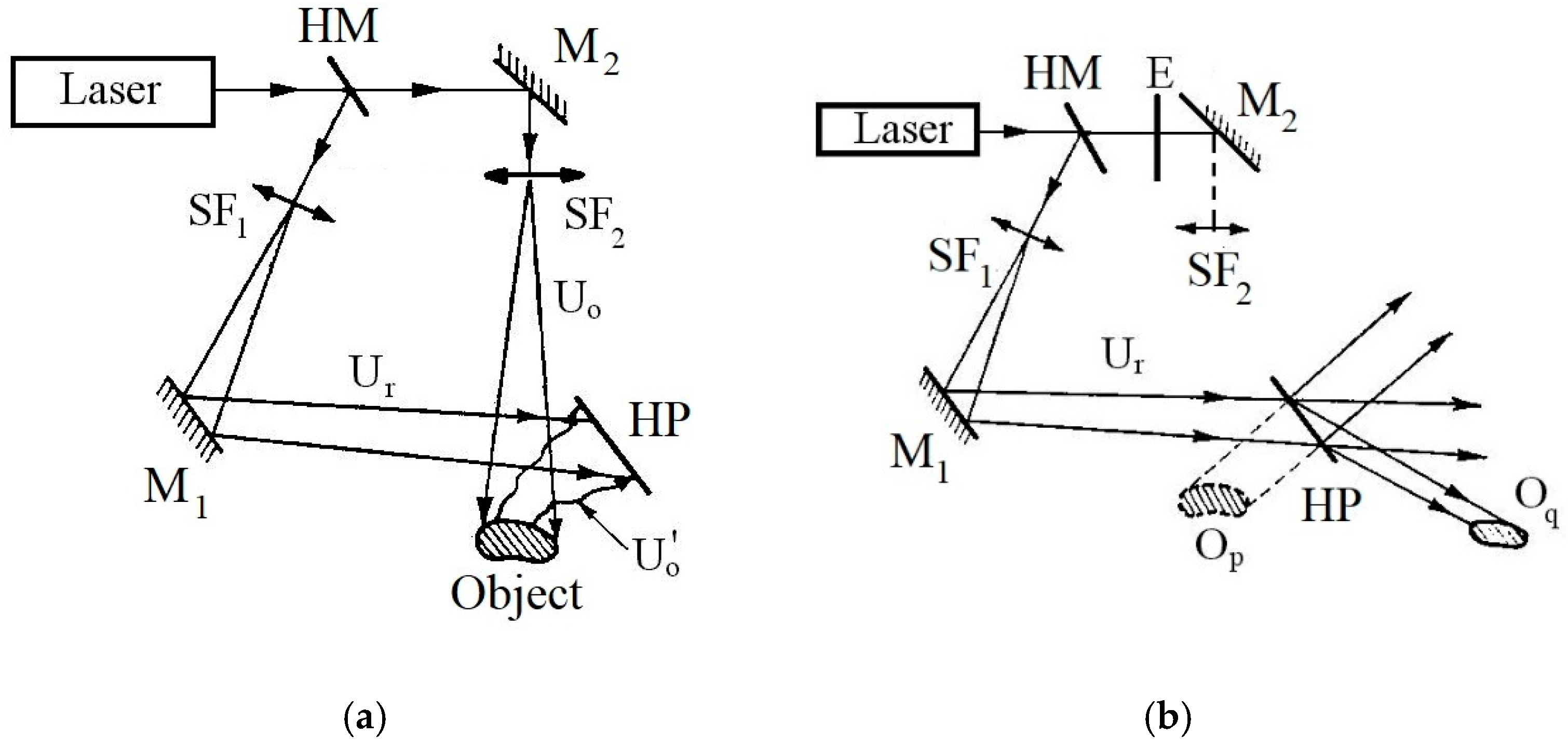
To the best of the authors’ knowledge, currently, the most precise experimental method is Holographic Interferometry (HI) [40,42,50,51]. It represents a particularly efficient combination of Optical Interferometry with Classical Holography (discovered in 1949 by Dennis Gábor), using a laser beam (intense, coherent, and monochromatic) as a light source. Depending on the distances between the observer, the holographic plate (HP), and the tested object, we distinguish Fresnel-type holograms when these distances are of the same order of magnitude or Fraunhofer–Fourier-type holograms when the object is at a much greater distance from the subject. In current technical measurements using HI, the Fresnel types are used (Figure 4a). The laser source emits an intense, coherent, monochromatic light beam with a diameter of approximately 1.5–2.0 mm. This beam is divided into two parts at the half-mirror (HM). These two parts have intensities that depend on the application; they vary with a ratio from 1:1 to 1:5 using the optical characteristics of the HM. The reflected wave, which is called the reference wave U r here, expands at the spatial filter SF1, becoming a broadened and filtered wave, so it has a perfect Gaussian distribution. By means of the mirror M1 (or, if necessary, a set of several mirrors), U r , which has been widened and has an increasingly larger diameter along the path travelled, directly reaches the HP, which it illuminates entirely. The HP is a high-resolution photosensitive plate of 7000–9000 lines/mm. During this time, with the help of the M2 mirror of the SF2 spatial filter, the wave that directly crosses HM, that is, the transmitted wave, called the object wave U o here, is widened and filtered when it reaches the surface of the object studied, which it illuminates entirely (obviously, only the surface visible to the Uo beam). This studied object must have a semi-matte and relatively rough surface so that each of its points functions as a secondary light source. Thus, the light incident on this surface, after reflecting from these points back into space, partially arrives at the HP. At the HP level, interference with U r occurs, as it is in phase (i.e., oscillates in phase) with Uo. This interference leads to the formation of a holographic image, i.e., a virtual 3D image of the tested object. To reconstruct this image (Figure 4b), an E screen is interposed in front of Uo, and even if the initial (real) object Op has been removed, its virtual 3D image, i.e., Oq, becomes visible to the observer behind the HP.
Let us divide the initial exposure time into two equal parts, one corresponding to the initial unloaded (or preloaded) state of the tested object and the second corresponding to its loaded (mechanical, thermal, etc.) one. Consequently, two exposures will have one corresponding to the initial state and a second responding to the effective loaded state. After the usual photo process of development–fixation–drying, upon reconstruction, a series of fringes (black stripes, with a certain 3D distribution and density) appear on this virtual 3D image, which represents a geometric locus of the object points with identical 3D displacements; the excess displacement from one fringe to another is of the order of 10–15 nm. This is the principle of HI with double exposure; it only provides information regarding the relative deformation produced for a given load compared with the initial state (unloaded or preloaded) of the analyzed body. However, if the exposure is made only for the initial state of the object (with half the initial exposure time set), followed by the usual photo process of development–fixation–drying, as well as a repositioning with submicron precision of the HP to its initial place, then one will achieve HI in real time. In this case, for each distinct loading state, a separate reconstruction is obtained, with fringe fields that have distinct shapes, densities, and distributions. To avoid an impermissibly high increase in the fringe density, which leads to the definitive compromise of the fringe field evaluation, we must impose a strict limitation on the maximum displacement, namely,
δ max λ / 4
where λ represents the wavelength of the laser beam used. In the current case, when a HeNe gas laser is used, this wavelength is λ = 632.8 nm; therefore, we have
δ max λ / 4 158.2   nm
As can be seen, a real-time HP from HI is equivalent to a series of measurements from HI with double exposure; obviously, in the first, we not only save time and materials but also have the possibility to follow the phenomenon under semi-dynamic conditions. Although HI represents a very precise experimental method, it has several shortcomings, which have currently reduced its scope of applicability only to fundamental research.
Among its major shortcomings, if not applied to vibration analysis, we can mention the following:
  • It requires particularly rigorous vibration insulation of the laboratory (as it is only a laboratory method, not a field method, it cannot be applied in working/factory conditions);
  • The consumables are particularly expensive, especially the HPs;
  • The fringe field evaluation, with the exception of some specific optical settings, is difficult and time-consuming;
  • If the common HI technique is applied, then the (3) δ max λ / 4 158.2   nm condition offers a significant limitation.
On the contrary, with the so-called “cascade” technique (where the final loading state of the first case is the preloaded one for the second stage, etc.), the limit of the maximum displacement becomes greater.
In the 1980s and 1990s, until the advent and widespread application of CCD cameras, HI was the method of choice in many areas of cutting-edge engineering, as well as in biomechanics, The authors of this contribution applied its advantages to the study of intact and fractured human long bones [52,53,54].
At the end of the 1990s, with the implementation of CCD cameras in measurement techniques, especially those of deformations, a powerful new method appeared, which presents the main advantages of being able to be applied in working conditions (not only in the lab). It has two versions: Electronic Speckle Pattern Interferometry (ESPI) and Shearography [55]. The principle setup of Shearography system is shown in the Figure 5. Both of them use the same optical system; the difference consists in the foreseen shearing of the image, which is analyzed below. They have a slightly lower accuracy than HI, i.e., about (20…25) mn.
In the case of Shearography, object (1) is subjected to tests, while in ESPI, there is a set consisting of the tested object and, close to it, a small reference object with minimal thermal expansion properties, such as a small piece of quartz glass. A comparison of the image that belongs to the small and unloaded plate with that of the specimen makes possible a good and accurate in-plane strain analysis (this will be defined below as overlapping or shear amount). The last approach is the ESPI with reference plate method. The use of laser diodes (2 and 3), which are positioned symmetrically with respect to the tested object (1) and fixed onto highly stiffened polycarbonate rods (6, 7), assures good stability by their mounting on a stable tripod. Of course, the above-mentioned elements (2, 3, 6, and 7), together with the Michelson interferometer (5) and the CCD camera (4), which are pointed in the normal direction to the object, are also mounted on the same stable tripod, thus forming a compact and easy-to-transport optical system. For a better and easier understanding of the real working principle of this ESPI/Shearography system, let us have a look inside the above-mentioned Michelson interferometer according to [55] (Figure 6).
There are two or four special laser diodes, which assure a coherent, monochromatic, powerful lighting of the tested object; in Figure 6, only one of them is represented. From the diffusely scattering surface of the illuminated object, each surface point acts as a secondary light source, which reflects the incoming light (in every direction). Thus, a part of the incident light will arrive at the CCD camera, where, in the focal plane of the camera, one obtains the image of the object. In this sense, the light passes through the Michelson interferometer, which consists of a divisor cube and two mirrors (shear mirror and phase shift mirror). By tilting the shear mirror with a small angle of α s / 2 , two points on the surface of the object (P1 and P2) will be superposed at a single point P of the focal plane. Therefore, the corresponding light beam paths interfere on the focal plane of the camera (in the image plane). The corresponding shear amount
δ x = P 1 P 2
of the mentioned shear angle α s can be set in various axial directions, depending, of course, on the spatial positioning of the laser diodes. Using the second mirror (phase shift mirror) of the Michelson interferometer, one can actively create light path changes for one of the partial beams; currently, for an accurate displacement evaluation, 3–4 different sets of images are captured. Consequently, by using multiple intensity measurements with actively altered light path changes for the partial beam, we can determine the relative phase length for the respective pixel Δ (in the image plane of the camera) with respect to the interference phenomenon. In static loading cases, Δ represents the relative phase changes between two states of the analyzed object. In practical applications, corresponding to a relatively small overlap (shear amount), we have Shearography; for a large overlap, we have ESPI (with the Reference Plate Method). In the case of ESPI/Shearography, the “cascade” technique, using simple software, avoids the cumbersome HI evaluation of the fringe field. It is true that it has a slightly lower accuracy than HI. However, its simplicity and ease of application in static, quasi-dynamic, and dynamic problems have led to its current use in engineering and biomechanics. It should not be forgotten that in ESPI/Shearography, one no longer has expensive consumables; there are no vibration-insulation problems, nor are there any difficult fringe evaluation protocols. The software ensures an efficient and fast evaluation of displacements and strains, with graphic support appropriate to modern applications. A relatively small investigation area is recommended for static applications, but for quasi-dynamic and dynamic applications, much larger areas of the tested objects are recommended.
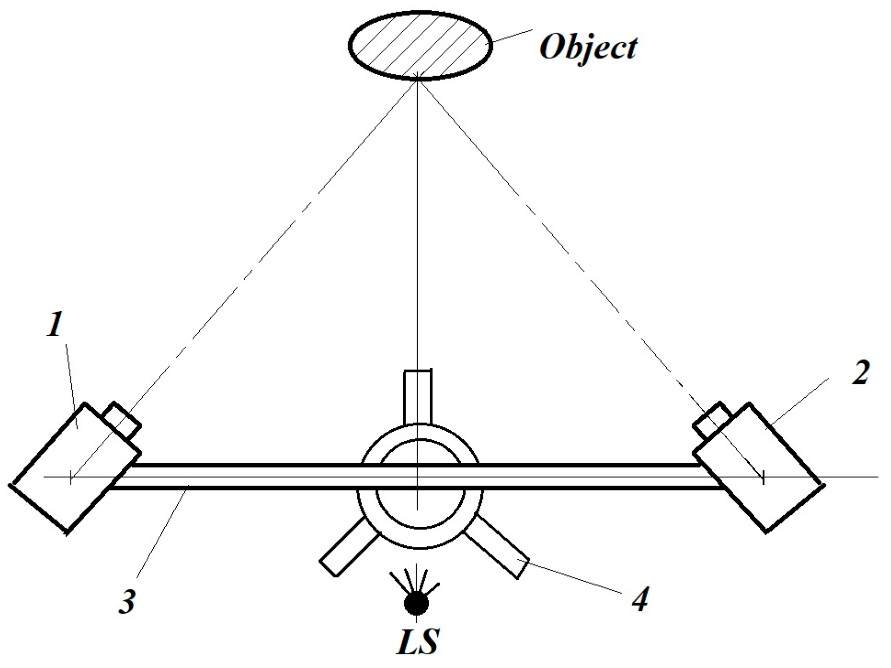
Video Image Correlation (VIC), also called Digital Image Correlation (DIC), is the last full-field experimental method developed after the 1990s, together with CCD cameras [56,57,58]. Figure 7 presents a 3D version thereof.
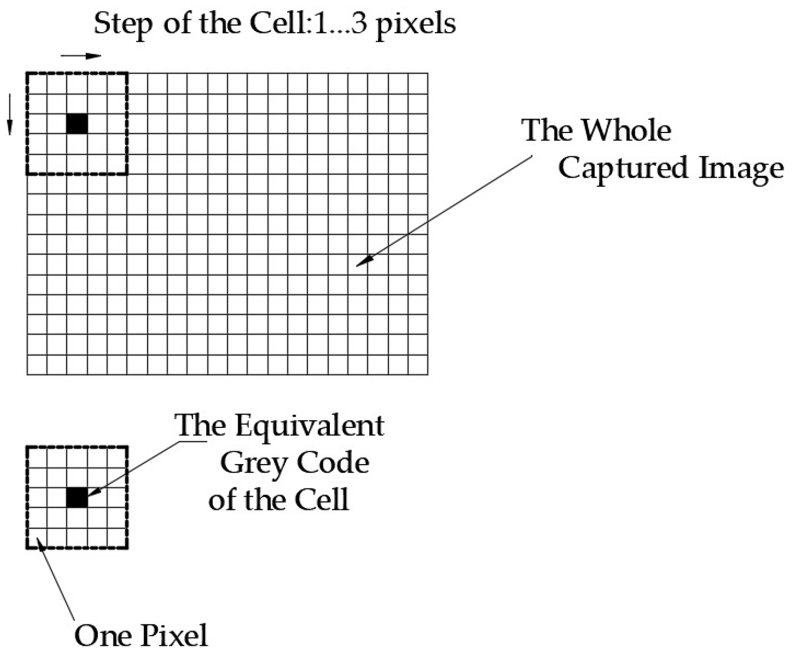
This system, intended for monitoring the 3D fields of displacements, deformations, and strains, consists of the following main components. There are two CCD cameras (1 and 2) that are symmetrically arranged with respect to the normal to the surface of the studied object. The CCD cameras are mounted on a rigid aluminum bar (3), which, in turn, is fixed on an equally stable tripod (4), ensuring the good stability of this optical system. The uniform illumination of the surface of the tested object, provided by a natural or conventional artificial SL light source, contributes to high-quality image capture. The surface of the object is painted with a matte black ground (white or black), on which speckles (black or white to ensure a good contrast with the background) are applied. The applied speckles have a random shape, size, and distribution. In advance of the measurements, by placing and rotating a special plate in the plane of the object to be analyzed, one performs the calibration of the VIC system. After calibration, a set of images (left and right) is captured with the CCD cameras for the unloaded (or preloaded) state of the object, followed by the actual acquisition, with a preset (given/desired) frequency, of image sequences during its loading. Each acquired image (left and right) will have a pixel size of 5.5 = 25. The software offers the possibility of selection of the area of interest (AOI), the subset (primarily cell) dimensions (here, 5.5 = 25 pixels), and the step size for moving/translating the subset in the horizontal and vertical directions to analyze (to sweep) the entire image of 5.5 = 25 n × m pixels, as shown in Figure 8. The software for this subset establishes/determines a unique gray code that is correlated to its median pixel’s high-accuracy 3D positioning (marked in black in the figure). By analyzing the whole image (by sweeping it with a pre-selected step—a number of pixels—without leaving the previous subset entirely), each subset also receives a nominated (unique) high-accuracy 3D positioning and a unique gray code. Consequently, the software substitutes these n × m pixel images with a limited number of characteristic points of the above-mentioned subsets, which have both a unique gray code and uniquely defined high-accuracy 3D coordinates. Thus, during the loading of the object, the displacement vectors and their corresponding 3D projections of these characteristic points (of course, only from the AOI) offer not only the displacement field but also the corresponding strain field.
One can underline that the VIC-3D system practically fully satisfies all of the requirements of a precise, efficient, and user-friendly experimental investigation method.
The following main advantages of the VIC-3D systems must be demonstrated [42,56,57,58]:
  • It is a contactless method; thus, it does not influence the analyzed phenomenon.
  • It can be applied to many types of materials, including metals, wood, plastics, bones, and composites.
  • It does not require expensive consumables, only some water-soluble paints (black and white), which can be easily cleaned after the experiments.
  • Depending on the given optical set, it can monitor surfaces starting from some cm2 up to some m2—in the domain of 3D displacements, 1   μ m to several cm—with practically the same accuracy/precision.
  • With the ability to apply the virtual strain gauge option, it serves as an integral substitution for ESG systems in the analysis of not only static but also quasi-dynamic and dynamic phenomena.
  • As a virtual experimental method, the captured images can be reloaded and re-evaluated based on other accuracies (other subsets and step sizes, as well as other new AOIs) for smaller or larger investigation areas.
  • One can define several lines and curves with the desired constitutive points, along which one can obtain the desired displacements, strains, and other useful engineering information based on several post-processing tools (given in advance or developed by the user).
  • It represents a high-credibility validation tool for FEM analysis and developed models.

3. The Authors’ Own Results and Discussion

3.1. New Approaches with the ESG Technique

Based on the brief analysis of the achievements at the global level, which is obviously not exhaustive, the authors attempted to highlight the contribution of experimental methods to medical action, especially with reference to surgery on fractured human long bones. This investigation is part of a larger contribution of specialists from different fields (applied mathematics, FEM, mathematical statistics, etc.) to the efficiency of the medical act of surgery. Taking the achievements by specialists in the field of experimental methods analyzed in Section 1.2 into account, the authors of the present contribution try to complete them with some useful aspects, especially in the fields of ESG and VIC-3D, in which, over the years, they have obtained some useful results for orthopedic doctors.
In Section 2.1, when analyzing the ESG method, it was mentioned that the direct application of SGs to human bones not only presents several technical shortcomings but is also quite inefficient in most cases. The authors then offer an alternative solution that practically eliminates these shortcomings, but at least reduces them in all cases.
In this regard, monitoring the relative displacements between fractured parts, especially in the case of elastic fixators, raises serious problems due to the magnitude of these displacements, which far exceed the measurement range of ESGs. In addition, a direct application of SGs right at the fracture level is impossible by definition. In the study of the relative behavior of fractured parts in the case of elastic fixators (Ender nails or/and „8″-shaped thin wire loops), ultimately, comparing the efficiency of different types of fixators through Perren’s theory [4] involves monitoring relatively large displacement fields of 0.5, …4.0 mm, with which fractured parts can move relatively.
At first glance, monitoring of displacements of this magnitude would be possible only with the VIC-3D optical system. However, this becomes possible with the help of an original set of SG-based displacement transducers designed and applied by the authors.
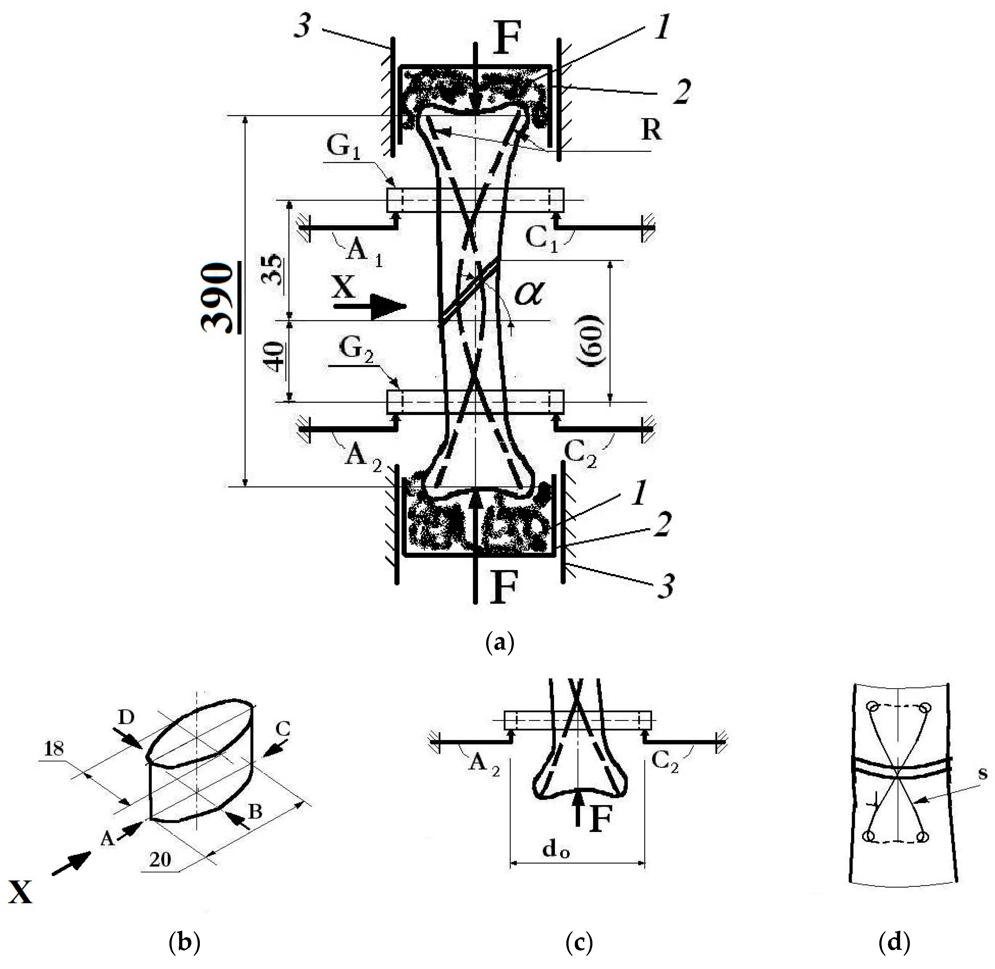
Let us consider the case of an unstable fracture, fixed with the help of two elastic Ender nails and an „8″-shaped thin wire loop [59] (Figure 9).
In principle, the stand, designed and tested by the authors, has the following basic elements: the slides (3) are rigidly fixed on an external support (here, some car cylinder liners), in which the special parts (2) are sliding-mounted (here, some car pistons, which were also equipped with their segments, to ensure a smooth sliding motion). In these pistons, with medical ipsum, the two parts of the tested fractured bone (here, a tibia) are fixed, previously provided with a certain type of fixator (internal Ender nails R, some „8″-shaped thin wire loops S, or some external fixators, which are not mentioned) [59]. The force F, applied by the mobile jaw of a universal tensile–compression testing machine, corresponds to the size of normal walking.
On the two fractured parts, we fix two rigid aluminum rings G1 and G2 with screws (without damaging the bone material). On these rings, there are four elastic lamellas A1, A2, B1, B2, C1, C2, D1, D2, and each of them is foreseen with full-bridge connected SGs. We mount these lamellas using a pre-tensioned touch to rings G1 and G2. It is known that a full-bridge connection integrally eliminates the unwanted influence of temperature variation during measurements. All lamellas, based on previous metrological calibrations, offer the desired electrical signal [mV] vs. displacement [µm] curves. The lamellas, which are fixed with some rigid external supports, remain in their initial positions during the loading of the tested bones.
Based on Figure 9b,c, which show the arrangement of the lamellas, it is possible to monitor the four-point displacement (A, B, C, D) and the linear and angular displacements. The latter represent the rotations along the AC and BD directions. This additional facility of the conceived testing bench allows the introduction of new criteria for an objective performance evaluation of the tested fixation systems (detailed below).
To eliminate the finite rigidity of the involved medical ipsum, the authors applied individual/separate monitoring of the displacements above and below the fracture, and their difference offers the high-accuracy relative displacement of the fractured bone parts (in the vertical direction) at levels A, B, C, and D. In addition, the fixation of the fractured long bones, especially in the median area, imposes a series of severe biomechanical conditions.
Many specialists believe that centro-medullary fixation (using elastic Ender nails) best satisfies these conditions, especially in the case of stable fractures (in which the fracture surfaces are practically perpendicular to the bone longitudinal axis), ensuring a rapid and quality recovery of the patient.
At first, these elastic fixations were not suitable in the case of unstable fractures, but in recent years, two constructive solutions have spread, namely, the additional use of the following:
  • Fixations, in the stretched area, with the help of 8-shaped thin wire loops at the level of the fracture center.
  • External fixation elements.
Among the primary goals of the research carried out in [59] was the comparison of such innovative solutions, which, in clinical practice, have demonstrated their effectiveness, but for which there were no clear biomechanical arguments.
Comparing the magnitude of inter-fragmentary movements of these new solutions provided the necessary explanation required by orthopedic doctors (as shown below).
The following primary results of [59] are the following:
  • The relative linear displacements (at the level of all pairs of lamellas) could be determined using simple relationships of the type
Δ A = δ A 1 δ A 2   μ m
where δA1 and δA2 represent the displacements suffered by the upper and lower parts of the bone, respectively, at the level of the A1A2 plane.
  • The average relative displacement becomes
    Δ = Δ A + Δ B + Δ C + Δ D 4     μ m
  • The angular ones, that is, those with relative rotation in two orthogonal planes, correspond to the following relative linear displacements:
    φ r e l   A C = a r c t g Δ A Δ C d 0 ,     deg
    and
φ r e l     D B = a r c t g Δ D Δ B d 0 ,   deg
where d0 is the distance of the location/arrangement of the lamellas from the bone (Figure 9c).
Based on these theoretical considerations, the authors carried out detailed investigations for four distinct cases of human tibia fixation:
  • P1—intact bone, which also served as a standard in the assessment of displacements.
  • P2—fracture fixation with only two elastic centro-medullary Ender nails.
  • P3—fracture fixation with two elastic centro-medullary Ender nails, combined with an external one-sided external fixator.
  • P4—fracture fixation with two elastic centro-medullary Ender nails, combined with an 8-shaped thin wire loop.
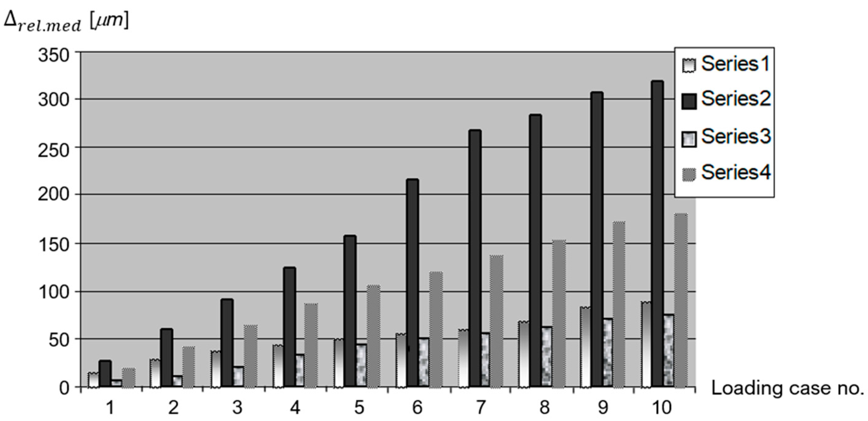
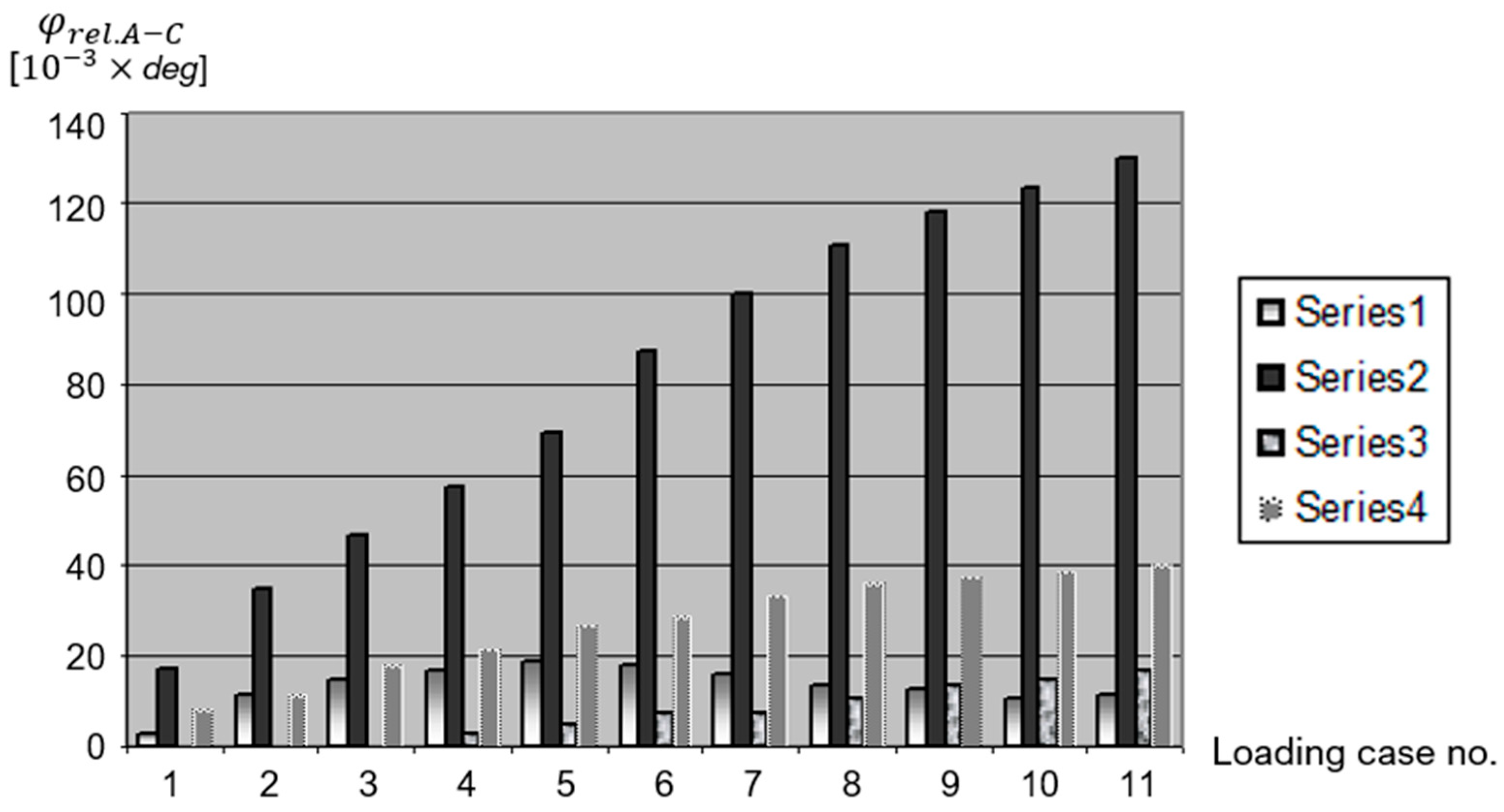
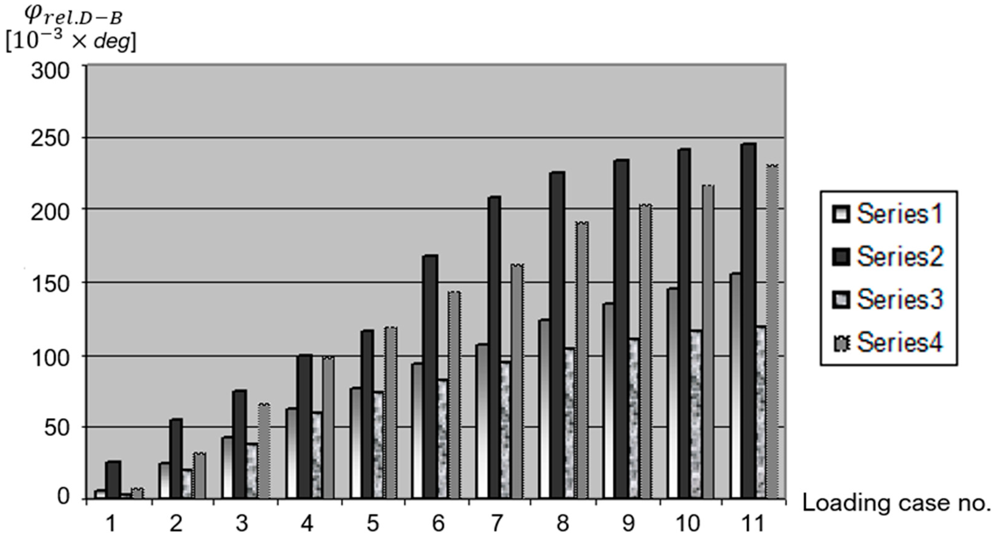
Figure 10, Figure 11 and Figure 12 offer diagrams of variations in these quantities depending on the load, divided into ten identical steps.
Based on these comparative results, one can formulate the following preliminary conclusions:
  • This original stand and measurement strategy of the authors can serve as an efficient, highly precise, and objective tool in assessing the quality of different types of fixators for both stable and unstable fractures.
  • By supplementing Ender nails with either an 8-shaped thin wire loop or an external fixator, unstable fractures will become more stable, and the healing period will be reduced due to the fact that these additional systems will also provide beneficial micro-movements for rapid healing.
  • The experimental results obtained could serve as solid scientific arguments in explaining rapid healing by applying these combined elastic fixation systems.
In [60], the authors performed a detailed comparative analysis of the efficiency of fixations with Ender-type elastic nails combined with an 8-shaped thin wire loop in 39 clinical cases of unstable fractures, which comprised 14 oblique or spiroid tibial shaft fractures (7 closed, 7 open grade I) and 25 humeral shaft fractures (22 closed and 3 open).
In another 14 clinical cases of deeply unstable fractures of the lower limbs (10 tibial and 4 femoral), surgical doctors combined elastic internal fixators with external fixators. A partial weight bearing at the end of the first month is recommended in tibial fractures. Based on clinical observations, in the wiring method, the average time to reunite in tibial fractures was 8 weeks, and there was an average of 7 weeks with no complications in humeral fractures. In the case of the external fixation method, the average time to union was 10 weeks with no complications.
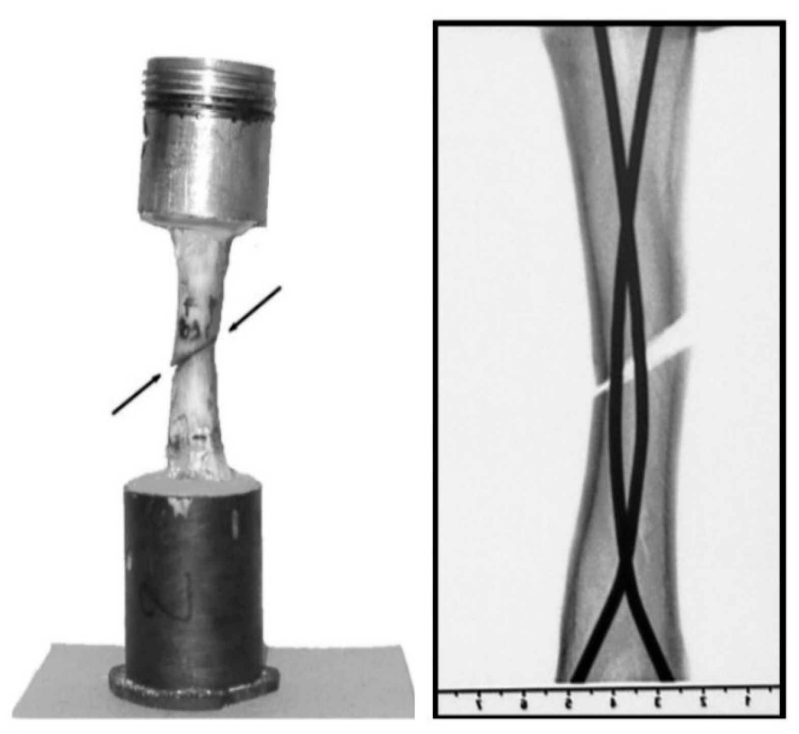
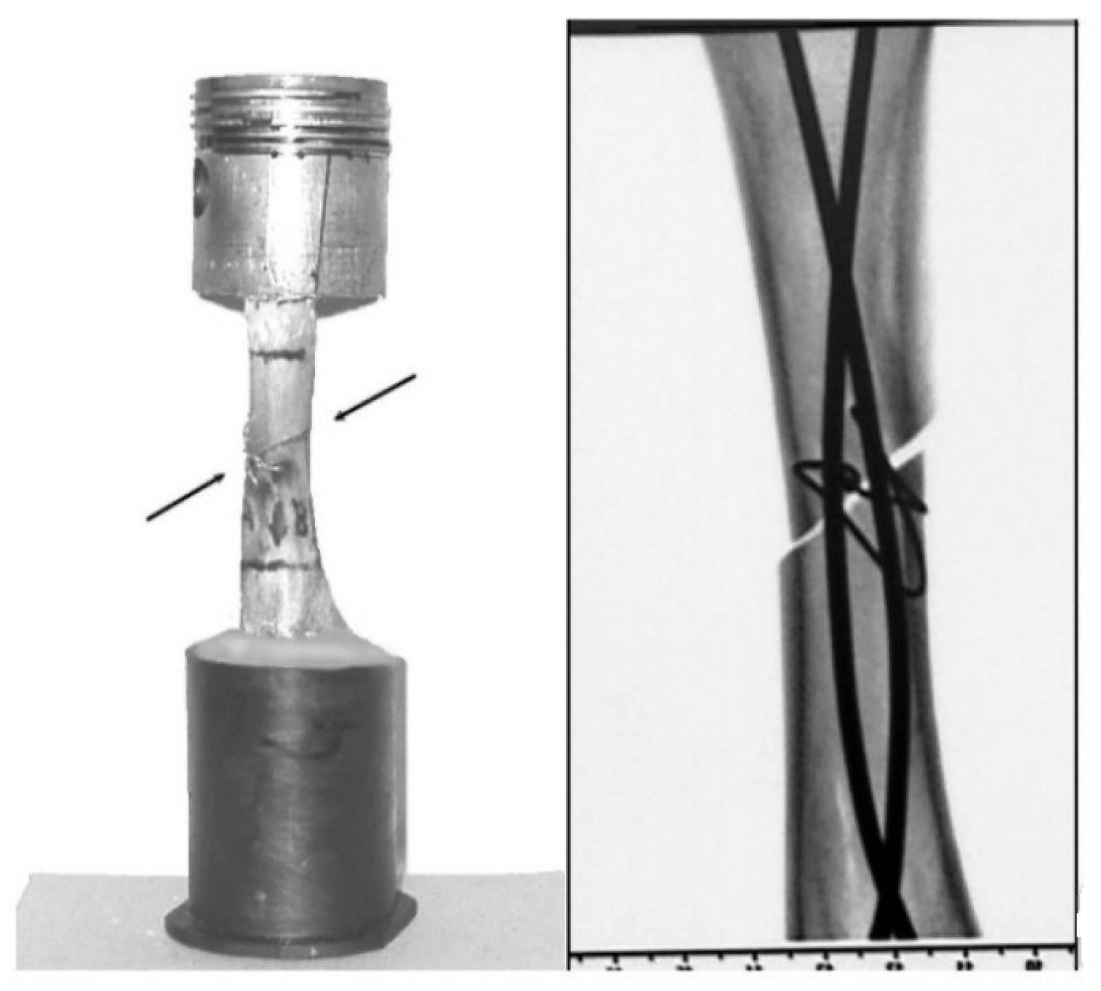
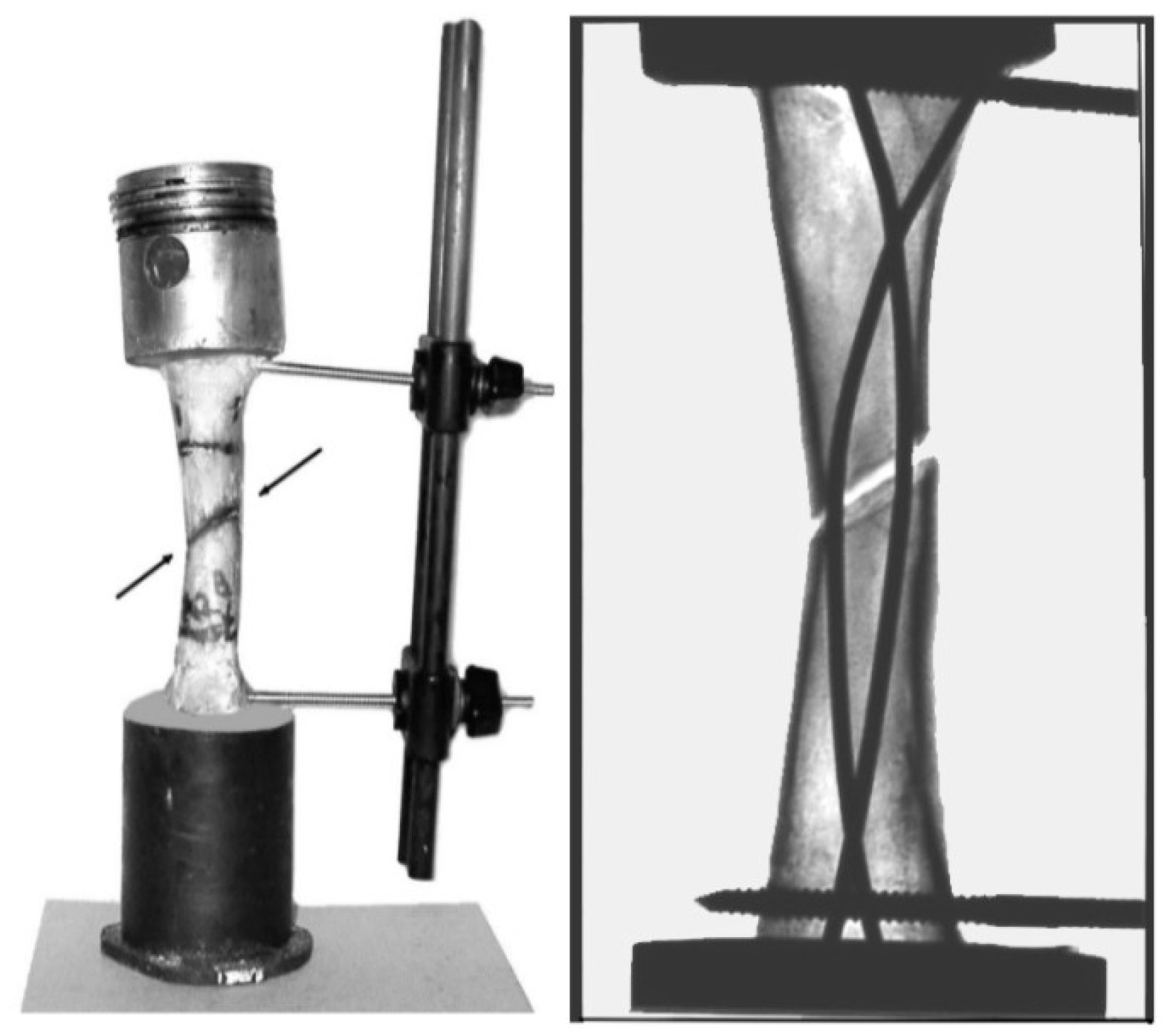
With this original ESG test bench, the authors tested fresh bovine bones with unstable fractures that had different types of fixators, namely, only with internal elastic nails (Figure 13), elastic nails combined with an 8-shaped thin wire loop (Figure 14), and elastic nails combined with external fixators (Figure 15). These figures show both photographs of the subassemblies made from the experiments and radiographs of their mid-sections.
The axial compression force, corresponding to the progressive loading of the bone in the first stage of healing, varied according to the law F = n∙8.312 N, where n = 1, …, 11.
The authors carried out detailed investigations for four distinct cases (that is, Series 1–4) of fixation, namely: P1, P2, P3 and P4.
The graphs presented in Figure 16, Figure 17 and Figure 18 also illustrate the efficiency of this original ESG test bench regarding the objective quantitative and qualitative evaluation of different types of fixators.
By carefully analyzing the experimental results [60], from Figure 18, the authors consider the method of electro-tensometrical investigation to be very efficient in the evaluation of different types of flexible fixation. They have several useful remarks, such as the following:
  • Using the association of a flexible fixation with “8″-shaped wiring or an external fixation causes a decrease in the movement of the fracture gap in the interval of beneficial micro-movements.
  • Furthermore, the rotation in the AC plane provides similar results for strain at the fracture site in the studied cases, while the BD plane does not reveal significant differences.
  • These experimental results, which are correlated with the clinical results, and the relative delay in forming a bone union in the patients with external fixations have an explanation in the rigidity of the fixation, which is very close to that of a normal bone.
  • In addition, they conclude that adding an “8″-shaped wiring or an external fixation is a very dynamic locking. This type of fixation retains the biomechanical advantages of a flexible fixation even in unstable fractures. This way of fixation is a biological one. It has a biological advantage by protecting the bone circulation and a mechanical one by allowing movements with a beneficial amplitude.
In [61,62], the authors optimized the test bench described above by using three lamellas instead of four, arranged angularly equidistant, i.e., 120° each, and fixed on three rigid vertical metal columns, with the possibility of sliding precisely up or down to ensure the desired position of the lamellas. The two rigid aluminum rings, replaced by two light but sufficiently rigid plastic plates and provided with a sufficiently densely marked grid, ensure the precise identification of the positioning of the lamella heads with respect to the center of the bone. These plastic plates, which are fixed with screws to the analyzed bone on the two sides of the fractures, perform up to down movements together with the parts of the fractured bone. Starting from the well-known fact that three points always define a plane, this information ensures that the displacement of the desired points or pairs of orthogonal points is appropriately obtained from the level of these plastic plates, wherever we consider them. Thus, it becomes possible to obtain much more complex and precise information regarding the relative linear and angular displacements with respect to the axis of intact or fractured bone.
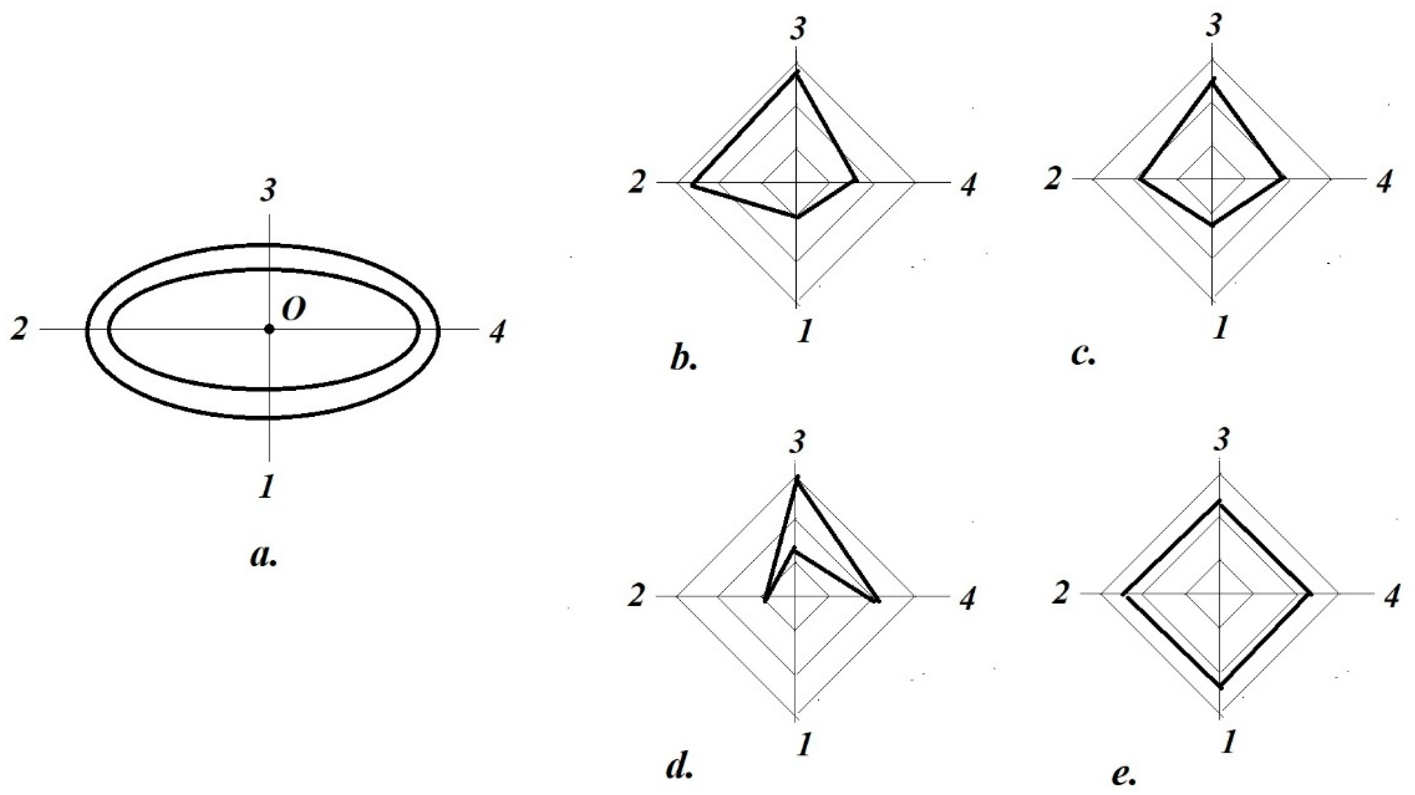
First, one must identify the geometric position of the center O of the analyzed bone. Based on the cyclic loads of the tested bone (either intact or fractured) and the indications of three pairs of lamellas, by means of simple analytical calculi, we determine the following. The relative linear and angular displacements of two pairs of points, arranged face to face (Figure 19a), marked here with Z1, …, Z4, are similar to those previously adapted for A, B, C, D (see Figure 19b). It should be mentioned that one pair of points is arranged/located/disposed in the plane of the fixator, and the other pair is in the orthogonal plane (similar to those from Figure 9). Let, for example, these pairs of points be (Z1, Z3) and (Z2, Z4), corresponding to the previous directions AC and BD.
The authors, together with orthopedic doctors, proposed a strategy for objectively evaluating the stabilization of each type of fixator.
From the measurement data, in relation to the four points selected in the two orthogonal directions (Z1, …, Z4), the following are determined:
  • The average relative displacements with respect to these pairs of points, i.e.,
    Δ m e d , 1 3 = Z 1 + Z 3 2   μ m ;   Δ m e d , 2 4 = Z 2 + Z 4 2   μ m ;
  • The corresponding relative rotations:
φ m e d , 1 3 = a r c t g Z 1 Z 3 2 r 0   deg ;   φ m e d , 2 4 = a r c t g Z 2 Z 4 2 r 0   deg ,
where r 0 represents the radius of the bone in the fracture section (a circular section is considered for this);
  • The global average displacement
Δ g l o b , 1 2 3 4 = Δ m e d , 1 3 + Δ m e d , 2 4 2   μ m ,
This is identical to relation (5).
  • The global linear strain:
ε g l o b , 1 2 3 4 = Δ g l o b , 1 2 3 4 h 0   ,
where h0 represents the initial distance of the two plastic plates at the level of the bone center.
  • The linear strains at the four significant points:
ε j = Z j h j     ,       j = 1 , ,   4 ,
where h j represents the initial distances of the two plastic plates at the level of conjugate points Z j and Z j arranged on the same vertical.
Based on these preliminary values, it became possible to introduce the following original indices of fixation stability:
  • The ratio between the extreme values (minimum and maximum) of the four specific linear strains:
    I ε = max ε 1 ,     ε 2   ,     ε 3   ,     ε 4 min ε 1 ,     ε 2   ,     ε 3   ,     ε 4   ;
  • The ratio between the maximum and minimum values of the linear strains and the global one:
    I ε , max = max ε 1 ,     ε 2   ,     ε 3   ,     ε 4 ε g l o b , 1 2 3 4   ;
    I ε , min = min ε 1 ,     ε 2   ,     ε 3   ,     ε 4 ε g l o b , 1 2 3 4   ;
  • The ratio of the two relative rotations:
    I φ = φ t o t , 1 3 φ t o t , 2 4   .
In addition, the arrangement of these ε j = Z j h j ,       j = 1 , ,   4 values in a polar diagram provides particularly suggestive information about the uniformity of stabilities in the four directions, as illustrated below.
Let us consider a conventional cross-section of a bone, where the four monitoring points Z1, …, Z4 are along the verticals (1, …, 4) (Figure 19a).
The authors agreed on the following conventions in the evaluation: the external fixation plate should be located along the vertical of 1; the plane of the secant arch of the Ender nails should coincide with the vertical plane of directions 24; the external fixator should have its location plane be that of the vertical plane of directions 13. With placement in these types of coordinates, on a convenient scale, the average values of the relative linear displacements obtained after an identical number of loading–unloading cycles (in the interval F = (400…850) N, i.e., Z r e l , m e d ,   j μ m ,   j = 1 , 2 , 3 , 4 ) results in diagrams with particularly varied shapes and sizes.
Thus, in the case of a Dynamic Compression Plate (DCP) with an entire loading–unloading cycle, the shape shown in Figure 19b is obtained, and the ascending part of the applied force is shown in Figure 19c. From the latter, we have the following useful element: on the plate side, we observe the smallest displacements (the system is the most rigid because the applied force is taken over by the plate).
On the opposite side of the plate (after direction 3), the largest displacements are observed (therefore, maximum elasticity). In the orthogonal plane (24), the displacements are practically similar, as their values are intermediate between directions 1 and 3. Obviously, depending on the type of fracture trajectory, stabilization peculiarities interfere, so these values can become unequal. In the case of pre-stressed compaction of the DCP, during the loading period, a phenomenon of rotation with respect to the plate axis (parallel to directions 24) occurs, as is clearly shown in Figure 19d. The last diagram in Figure 19e refers to the case of a Kuntcher rod with a bore for a human tibia, where, corresponding to the loading period, a practically uniform compression occurs in the focus by telescoping on the centro-medullary rod.
Other quantities resulting from this type of investigation with this original test bench are the following [63]:
  • Bending indices along
    axis   1 3   α 1 3 = max ( Z 1 ;   Z 3 ) min ( Z 1 ;   Z 3 )
    axis   2 4   β 2 4 = max ( Z 2 ;   Z 4 ) min ( Z 2 ;   Z 4 )
  • Slip index (of tangential instability):
γ = a v g ( Z 1 ;   Z 3 ) a v g ( Z 2 ;   Z 4 )
where avg represents the average value.

3.2. New Approaches to the DIC/VIC Technique

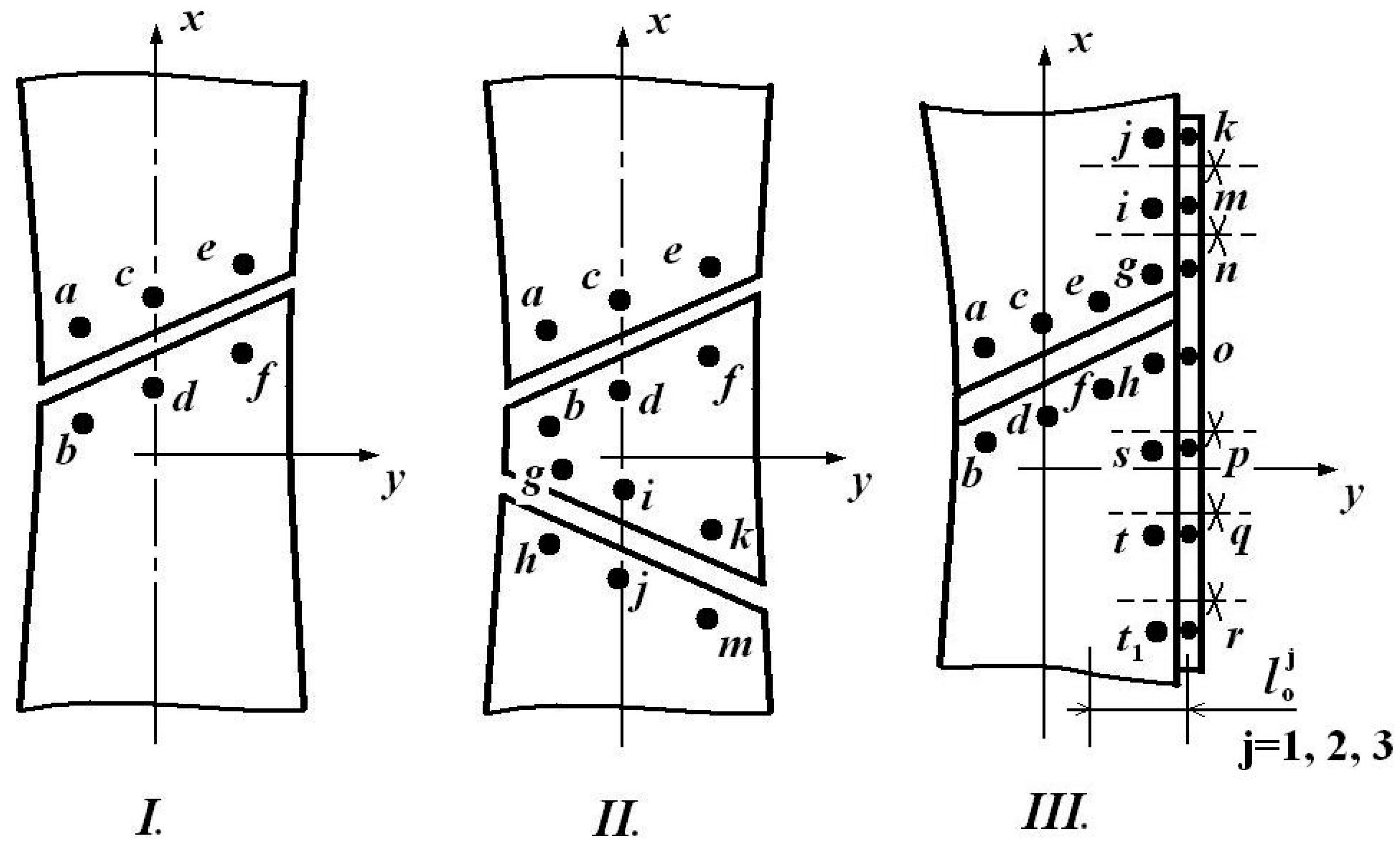
In addition to the facilities offered by their original ESG test benches, in [64], the authors of the present contribution synthesized the main results obtained with the VIC-3D system, illustrating its undeniable abilities. They carried out a comparative analysis of some types of fixation on preserved human bones (femur and tibia), as well as on fresh bovine bones (femur). In Figure 20, two cases are illustrated: how the color-coded linear and angular displacement fields, as well as the corresponding strain fields, ensure the high-accuracy monitoring (with microns) of the loaded bones.
In principle, based on a prior calibration of the VIC-3D optical system, by subjecting the bone provided with the fixator to compression, images were captured/acquired by the two CCD cameras. Subsequently, we defined the area of interest (AOI) on which the software performed adequate calculations of the appropriate linear and angular displacements, as well as the corresponding strains, too. In this case, the displacements at the level of the points arranged near the external fixators (titanium or chromium plates, fixed with some special screws) or on the bone and near the fracture (in the case of internal fixators) were of major interest. Figure 21 shows the authors’ original strategy regarding the evaluation of the points selected from the VIC-3D data.
First, we select, along some predefined/desired lines on both sides of the fracture zone (e.g., s p ), several points (sufficiently numerous to provide conclusive information). For each pair thus selected, the following are determined (the software provides the initial data in Excel for this purpose): their initial distance l s p 0 ; the elongation/shortening of this segment Δ l s p ; their projections on the coordinate axes, as well as the corresponding linear strains εx, εy, εz.
In [64], these evaluation results were analyzed. To illustrate the accuracy and efficiency of the VIC-3D method, we provide some of the most significant results here.
Thus, e.g., for case III in Figure 21, the authors compared the measurement results for two types of fixators, that is, a DCP plate and a bridge plate. The authors selected seven points on both the edge of the fixation plate and the fractured bone, in the vicinity of the fixation plate, at different distances l 0 j , j = 1 ,     2 ,     3 . In a specific case, we had relative distances l 0 1 = 4.5     mm , l 0 2 = 7.0     mm , and l 0 3 = 10.0     mm between the points located on the plate and the fractured bone.
Corresponding to several complete loading–unloading cycles of up to 400 N, Table 1 presents the results in the case of the analyzed bovine femur [64].
Based on a careful analysis, it can be seen that, in the case of the DCP, without it undergoing bending overload (which operates on the principle of compression of the fractured area), corresponding to a force of 400 N, a more positive linear (tensile) strain is obtained than that on the opposite side of the plate. On the opposite side, corresponding to an applied compressive load, unloading (de-stressing) occurs. In principle, the bridge plate, subjected to a bending overload, leads to a 40% decrease in the longitudinal linear strain, as one can observe for ε y in Table 1.
If we use a bridge plate, the micro-displacements along the y-axis represent some slippage between the two surfaces. In the absence of bending overload, a rotational movement along the longitudinal axis of the plate occurs, and in this case, the limit value of the linear strain ε y of the inter-fragment, corresponding to a stable fixation of 0.02%, is exceeded.
On the other hand, the bridge plate fixator is designed for fractures with a high degree of instability. When one needs to monitor the relative movements of fractured parts, it is necessary to choose pairs of points on one and the other side of the fracture (e.g., the points a–b from case III, Figure 21).

4. Critical Analysis of the Described ESG Test Bench

The ESG test bench briefly presented in Figure 9 of Section 3 may raise several questions for the reader regarding the efficiency, precision, and repeatability of experiments under identical conditions.
To clarify these concerns, the authors further provide a more detailed description, which may serve as a useful starting point for others in developing even more powerful research equipment.
The authors, in choosing this solution for fixing/maintaining fractured bone, started from the consideration that the subassembly formed by the cylinder and piston, provided with its initial segments, satisfies both the requirements of regulation with minimal energy losses through friction and those related to stability. If we consider the fact that in the case of an internal combustion engine (at cycles of 4–5000 revolutions/minute and forces well above the values applied here in biomedical tests, i.e., over F = 1000   N ), these subassemblies ensure operation without shocks and oscillations; then we could assume that, in static conditions or with a reduced number of cycles per minute, these requirements (i.e., minimal energy losses through friction, respectively stable movement, without oscillations) will be ensured.
In addition, considering the dimensions of the piston, i.e., a diameter of ϕ p i s t o n = 95 0.038 0.020   mm and height of H p i s t o n = 75   mm , as well as the type of related adjustment (sliding, with a cold clearance between 0.020 and 0.038 mm), according to Figure 22a, even if, for some unknown reason, a rotation of the piston-segment subassembly were to occur, it would only have an angle of β = t g 1 ( 0.038 75 ) = 0.029 0 , which is totally insignificant from the point of view of the changes produced in the magnitude of the force F applied to the tested bone by means of the piston.
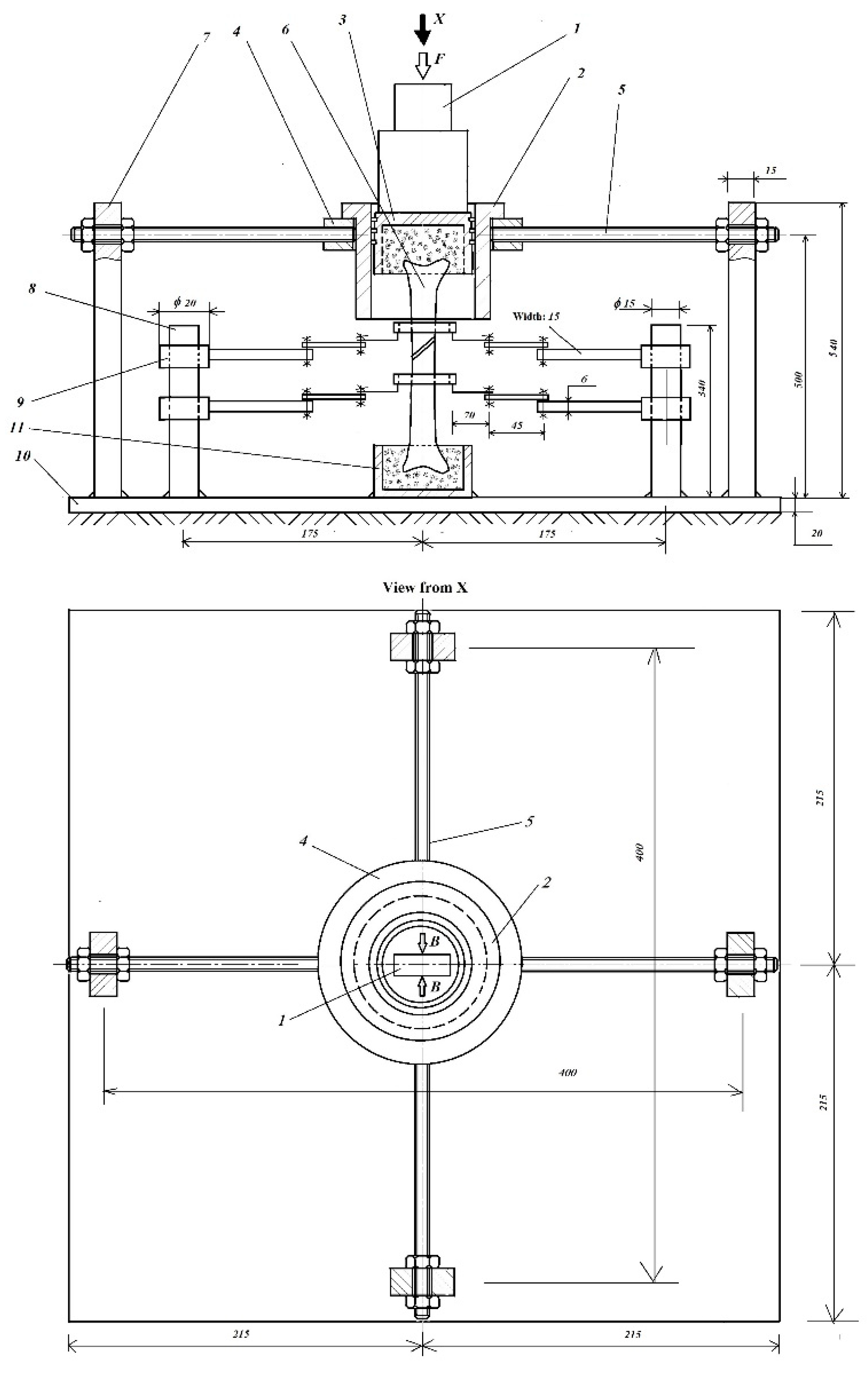
As will be seen below, the piston, in turn, is driven by a special part (1) (Figure 23), which is fixed to the movable head (mobile jaw) of the universal tensile–compression testing machine. This additionally forces the piston to strictly maintain its initial vertical direction of movement. When assembling this special part (1), its rigorous vertical fixation to the movable jaw of the testing machine is carefully checked. Thus, the application of the pressing force F on the upper end of the piston will also be carried out under strictly vertical conditions.
Let us now consider the case of a fractured human long bone, loaded in compression (femur of h = 390   mm in length), in which the fractured parts are reunited by means of an elastic fixation system. Following compressive loading, this elastic fixation system would allow a relative displacement of the parts of δ = 3   mm (Figure 22b). If we consider an adduction angle of α = 15 0 , then a simple calculation would result in the magnitude of e = h t g α = 390 t g 15 0 = 104.5   mm , as well as in the axial component (along the nominal axis of the femur) of the applied force F. In the case of F = 1000   N , this component would be F a = F cos α = 1000 cos 15 0 = 965.93   N .
In the case of femur failure (more precisely, its compression by δ = 3   mm ), the initial angle α changes to α 1 = t g 1 ( e h 3 ) = t g 1 ( 104.5 390 3 ) = 15.11 0 . This angular change corresponds to an axial component of the force applied by F 1 = F cos α 1 = 1000 cos 15.11 0 = 965.43   N , which represents an insignificant change. Moreover, in the analyzed case, the applied forces were of the order of 80 N, where these variations were even more insignificant.
It should also be noted that at the actual applied forces, which were of the order of 80 N, the medical ipsum functioned perfectly; no cracks in the medical ipsum could be observed inside the cavities/fixation areas of the bone.
Obviously, at forces of the order of F = 1000   N , corresponding to normal walking conditions, it is recommended to use acrylic adhesives or other adhesives with much higher strengths.
Since, according to the analyzed stresses, the mass of the medical ipsum did not suffer cracks, the ends of the fractured parts maintained their initial positions, without any additional stresses (such as torsion) compared with those that were initially expected.
The practically rigorous vertical movement of the upper end (of the piston and, with it, the bone) entitles us to believe that no other types of stresses appeared on the bone subjected to the tests.
This is even truer in the case of the tibia (Figure 9), where we do not have to deal with this adduction angle, as in the case of the femur, as the force is axial.
However, the authors used their VIC-3D optical system to perform additional tests and monitor the linear and angular deformation fields on the surfaces of the bones subjected to tests, which validated the results provided by the ESG lamellae with submicron precision/accuracy, confirming only the existence of the initially expected loads and their corresponding stresses.
Let us now focus on the displacement sensors (lamellae with ESGs). From the measurement technique, it is known that the fixation of any instrument must be made in a system with a stiffness that is at least 10 times higher than that of the monitored element (that subjected to tests). These prescriptions guided the authors both when they designed and tested their ESG lamellae and when they performed the monitoring of the relative displacements of the fractured parts of human bones, which we describe below.
As mentioned in Section 3, the direct application of ESGs to human bones presents several shortcomings, which is why the authors designed an original, safe, sensitive, and reusable ESG system for monitoring the relative displacements of fractured bone parts. Essentially, each sensor consisted of an elastic element (spring steel lamellae with a thickness of 0.3 mm) equipped with four ESGs, connected in a full Wheatstone bridge, which ensured not only the maximum electrical signal (and, thus, a high sensitivity) but also signal stability in the presence of temperature changes (Figure 24a).
Another known aspect of the measurement technique is that the initial sensor support with which the calibration was performed needed to be strictly maintained during the measurements. Otherwise, the calibration would not have the expected results. Therefore, before calibrating these lamellae, they were fixed definitively by means of M4 screws at the level of the bores (A) on a support made of an aluminum bar (Figure 24b), from which they were not subsequently dismantled (remaining all the time as intermediate parts between the ESG lamellae and their support, either on the calibration stand/test bench or on the bone monitoring stand/test bench). The subassemblies that were thus constituted (lamella–supports) were subsequently fixed by means of M6 screws at the level of the bores (B), first on the calibration test bench (Figure 25) and later on the fractured bone testing bench itself (Figures 27 and 28).
Individual calibration of each aluminum support–lamella subassembly was performed under metrological conditions (three loading–unloading cycles, taking their average values into account using a micrometer with an accuracy class of 0.1).
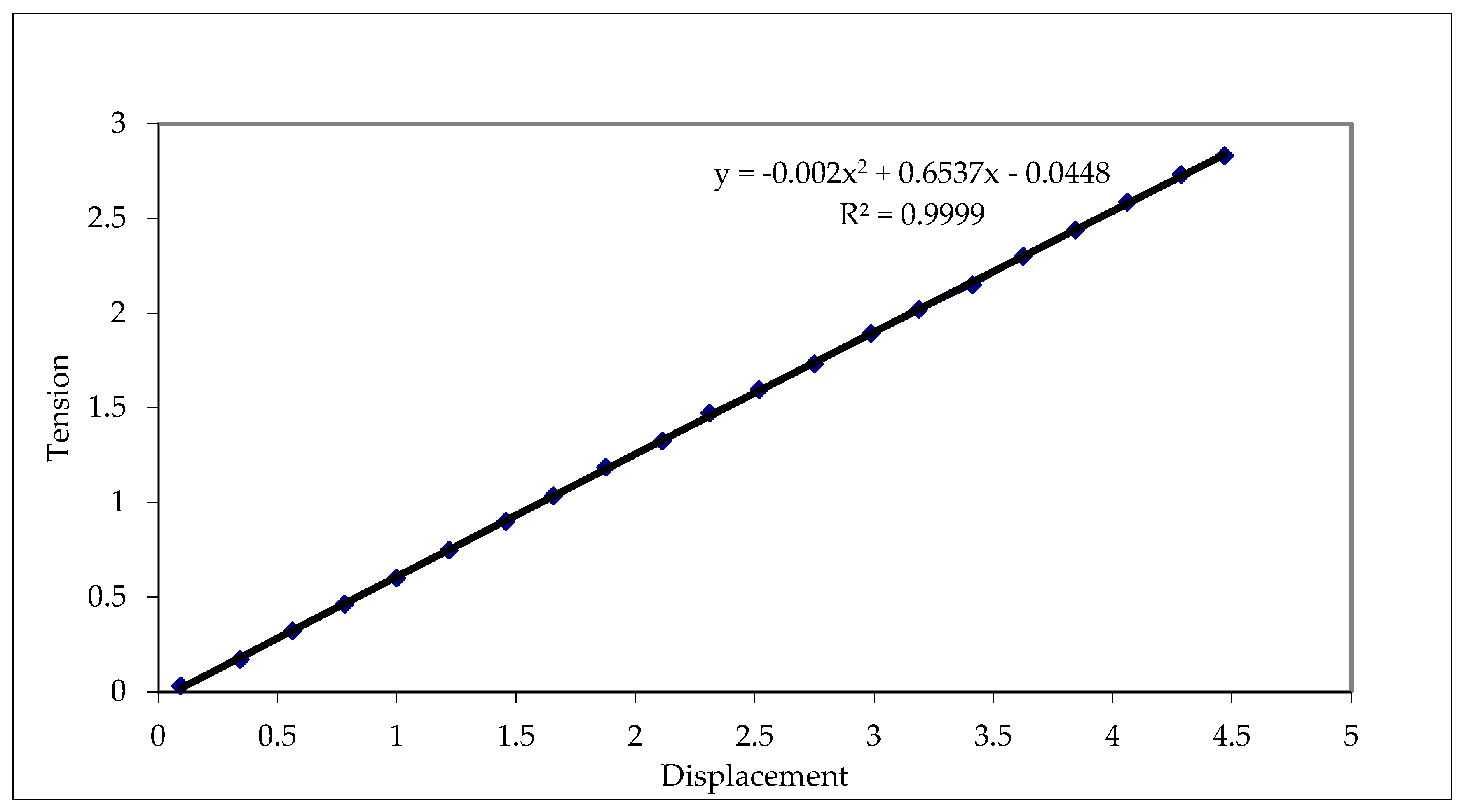
As an illustration of the sensitivity and repeatability of the indicated values, as well as the accuracy of these original sensors, Figure 26 shows the calibration curve of lamella #2.
From the second-order curve describing this transducer, the following emerges:
  • It is strongly linear (the second-order and zero terms are negligible compared with the first-order terms).
  • It has a high confidence/confidentiality coefficient of R 2 = 0.9999
  • It has a good sensitivity, i.e., the indication of 1 mV corresponds to a displacement of 1.67 μ m
The test bench briefly presented in Figure 9 has the following basic elements: a special actuator part (Figure 23), which is perfectly fixed vertically in the movable jaw of the tensile–compression testing machine, as well as an upper subassembly, illustrated in Figure 27, and the general assembly (Figure 28). It should be noted that before the piston’s assembly in the cylinder, the clamping shoulders of the piston pin are removed from the piston through mechanical processing, resulting in a cylindrical cavity with φ 85   mm , marked with a broken line, which constitutes the seat (D) of the upper end of the bone studied. At the level of the arrows (C), the movable jaws of the testing machine perfectly fix the special actuator part (1) in a vertical position. The four M14 screws, by screwing into the ring (4), ensure the rigid fixation of the upper subassembly. Subsequently, these M14 screws (Figure 28) are fixed in special rigid columns (7). As shown in Figure 9, the ends of the ESG lamellae rest on thin aluminum rings, which are fixed on the two sides of the fractured bone.
In the two cylindrical cavities (3 and 11), the ends of the fractured bone are fixed with medical ipsum. From the careful analysis of the dimensions of this test bench (see Figure 27 and Figure 28), as well as the lamella calibration bench, it can be seen that they satisfy the criteria of sufficiently rigid structures, which ensure both an adequate metrological calibration and the performance of measurements with credible and repeatable results.
Based on the tests performed by the authors using this test bench, which are later supplemented with the results of measurements with the VIC-3D optical system, providing submicron precision/accuracy in the evaluation of displacement and deformation fields, they conclude that there are no difficulties (or, at least, none were encountered) in monitoring the displacements of fractured bones, nor could potential sources of errors regarding load misalignment be identified.
As a future task, the authors will develop some special verification tests to also consider the complex biomechanical behaviors of fractured bone under realistic conditions.

5. Conclusions and Perspective

Based on a critical analysis of worldwide achievements and those of the authors, the following conclusions are drawn:
  • Their original ESG test benches, assisted by a high-precision data acquisition system (e.g., National Instruments with 32 channels), allow the development of a new strategy for objectively comparing the efficiency of different types of bone fixation (femoral or tibial fixation), especially in the case of unstable fractures.
  • In the authors’ opinion, their protocol, together with the obtained measurement results, will open new opportunities for biomechanics specialists, as well as for orthopedic doctors, to find optimal and personalized solutions for the fixation of fractured parts, as well as to provide surgeons with solid biomechanical arguments for the clinical effectiveness of the chosen fixators.
  • The proposed set of evaluation parameters, including the polar diagram intended for evaluating and comparing the linear displacements of the tested fixators, may represent an efficient and objective tool for evaluating the stability and effectiveness of a chosen fixator in the future.
  • The implementation of the VIC-3D optical system in the evaluation of micro-displacements (both in the immediate area of external fixation plates with human bone and inter-fragmentary ones) will provide new opportunities to approach the surgical act.
  • The combination of these two approaches (ESG test benches and VIC-3D) will allow the development of a modern, unified, and original methodology for the most efficient quantitative and qualitative analysis of types of fixators.
  • Given the data acquisition facilities offered by this ESG and VID-3D testing system, their combination will ensure high accuracy and the desired loading speed (which can even be variable, if necessary, to simulate the effect of walking/using a particular limb); through these facilities, it will become a useful and comparatively particularly effective tool for performance evaluation.
  • Among the authors’ future goals is the development and validation of a more flexible and personalized fixation solution in cooperation with surgeons.

Author Contributions

Conceptualization, I.S. and I.Ș.; methodology, I.Ș. and D.-T.S.; software, T.-F.G. and I.-R.S.; validation, I.Ș. and D.-T.S.; formal analysis, T.-F.G. and I.-R.S.; investigation, I.Ș. and D.-T.S.; resources, I.S. and T.-F.G.; writing—original draft preparation, I.S. and T.-F.G.; writing—review and editing, I.S., T.-F.G., and I.-R.S.; supervision, I.Ș.; project administration, I.S. All authors have read and agreed to the published version of the manuscript.

Funding

This research received no external funding.

Data Availability Statement

The original contributions presented in the study are included in the article, further inquiries can be directed to the corresponding authors.

Conflicts of Interest

The authors declare no conflicts of interest.

References

  1. Horta, J.; Riverab, A.L.; De La Islaa, A.; Oskamb, A.; Victor, M.; Castanob, V.M. Fracture of Femur: Simulation and Photo-elasticity Analysis. Dig. J. Nanomater. Biostruct. 2013, 8, 177–185. [Google Scholar]
  2. Horta-Rangel, J.; Riviera, A.L.; Castano, V.M. Modal behavior of bones during fracture, Computer Methods in Biomechanics and Biomedical Engineering. Comput. Methods Biomech. Biomed. Eng. 2010, 13, 91–95. [Google Scholar] [CrossRef] [PubMed]
  3. Melchionda, R.; Scalise, L. Dynamic Characterization of a Human Tibia Including Soft Tissues: Experimental and Numerical Analysis. Master’s Thesis, Polytechnic University of Marche, Ancona, Italy, 2019. [Google Scholar]
  4. Perren, S.M. Evolution of the internal fixation of long bone fractures: The scientific basis of biological internal fixation: Choosing a new balance between stability and biology. J. Bone Jt. Surg. Br. 2002, 84, 1093–1110. [Google Scholar] [CrossRef]
  5. Müller, M.E.; Allgöwer, M.; Schneider, R.; Willenegger, H.; Perren, S.M. Manual of Internal Fixation, 3rd ed.; Springer: Berlin/Heidelberg, Germany, 1995; pp. 4–95. ISBN 978-3-540-55297-0. [Google Scholar]
  6. Perren, S.M. Physical and biological aspects of fracture healing with special reference to internal fixation. Clin. Orthop. Relat. Res. 1979, 138, 175–196. [Google Scholar] [PubMed]
  7. Perren, S.M.; Cordey, J. The Concept of Inter-Fragmentary Strain, in Current Concepts of Internal Fixation of Fractures; Springer: Berlin/Heidelberg, Germany, 1980; pp. 63–77. [Google Scholar]
  8. Necula, R.D.; Panait, G.h.; Száva, I.; Şamotă, I. Evaluation of Micro-movement in the biomechanical context of bone shaft fracture healing in elastic versus rigid fixations. Ann. Acad. Rom. Sci. 2011, 2, 65–78. [Google Scholar]
  9. Kenwright, J.; Goodship, A.E. Controlled Mechanical Stimulation in the Treatment of Tibial Fractures. Clin. Orthop. 1989, 241, 36–47. [Google Scholar] [CrossRef]
  10. Inacio, J.V.; Schwarzenberg, P.; Kantzos, A.; Malige, A.; Nwachuku, C.O.; Dailey, H.L. Rethinking the 10% strain rule in fracture healing: A distal femur fracture case series. J. Orthop. Res. 2023, 41, 1049–1059. [Google Scholar] [CrossRef]
  11. Coquim, J.; Clemenzi, J.; Salahi, M.; Sherif, A.; Avval, P.T.; Shah, S.; Schemitsch, E.H.; Bagheri, Z.S.; Bougherara, H.; Zdero, R. Biomechanical Analysis Using FEA and Experiments of Metal Plate and Bone Strut Repair of a Femur Midshaft Segmental Defect. BioMed Res. Int. J. 2018, 2018, 4650308. [Google Scholar] [CrossRef]
  12. Moazen, M.; Mak, J.H.; Etchels, L.W.; Jin, Z.; Wilcox, R.K.; Jones, A.C.; Tsiridis, E. Periprosthetic femoral fracture—A biomechanical comparison between Vancouver type B1 and B2 fixation methods. J. Arthroplast. 2014, 29, 3. [Google Scholar] [CrossRef]
  13. Moazen, M.; Jones, A.C.; Leonidou, A.; Jin, Z.; Wilcox, R.K.; Tsiridis, E. Rigid versus flexible plate fixation for periprosthetic femoral fracture-Computer modelling of a clinical case. Med. Eng. Phys. 2012, 34, 1041–1048. [Google Scholar] [CrossRef] [PubMed]
  14. Moazen, M.; Leonidou, A.; Pagkalos, J.; Marghoub, A.; Fagan, M.J.; Tsiridis, E. Application of far cortical locking technology in periprosthetic femoral fracture fixation: A biomechanical study. J. Arthroplast. 2016, 31, 1849–1856. [Google Scholar] [CrossRef]
  15. Geier, A.; Kebbach, M.; Soodmand, E.; Woernle, C.; Kluess, D.; Bader, R. Neuro-musculoskeletal flexible multibody simulation yields a framework for efficient bone failure risk assessment. Sci. Rep. 2019, 9, 6928. [Google Scholar] [CrossRef]
  16. Son, D.S.; Mehboob, H.; Chang, S.H. Simulation of the bone healing process of fractured long bones applied with a composite bone plate with consideration of the blood vessel growth. Compos. Part B Eng. 2014, 58, 443–450. [Google Scholar] [CrossRef]
  17. Mishra, N.R.; Singh, K.M.; Kumar, V. Biomechanical Analysis of Human Femur using Finite Element Method: A Review Study. Mater. Today Proc. 2022, 56, 384–389. [Google Scholar] [CrossRef]
  18. Sawbones. Vashon, WA, USA. Available online: https://www.sawbones.com/ (accessed on 20 December 2024).
  19. Lindsey, R.W.; Gugala, Z.; Milne, E.; Sun, M.; Gannon, F.H.; Latta, L.L. The efficacy of cylindrical titanium mesh cage for the reconstruction of a critical-size canine segmental femoral diaphyseal defect. J. Orthop. Res. 2006, 24, 1438–1453. [Google Scholar] [CrossRef] [PubMed]
  20. Wieding, J.; Souffrant, R.; Mittelmeier, W.; Bader, R. Finite element analysis on the biomechanical stability of open porous titanium scaffolds for large segmental bone defects under physiological load conditions. Med. Eng. Phys. 2013, 35, 422–432. [Google Scholar] [CrossRef]
  21. Talbot, M.; Zdero, R.; Garneau, D.; Cole, P.A.; Schemitsch, E.H. Fixation of long bone segmental defects: A biomechanical study. Injury 2008, 39, 181–186. [Google Scholar] [CrossRef] [PubMed]
  22. Juszczyk, M.M.; Cristofolini, L.; Viceconti, M. The human proximal femur behaves linearly elastic up to failure under physiological loading conditions. J. Biomech. 2011, 44, 2259–2266. [Google Scholar] [CrossRef]
  23. Kress, T.A.; Porta, D.J.; Snider, J.N.; Fuller, P.M.; Psihogios, J.P.; Heck, W.L.; Frick, S.J.; Wasserman, J.F. Fracture patterns of human cadaver long bones. Proc. IRCOBI 1995, 23, 155–169. [Google Scholar]
  24. Shiling Zhang, S.; Patel, D.; Brady, M.; Gambill, S.; Theivendran, K.; Deshmukh, S.; Leslie, L.J. Experimental testing of fracture fixation plates: A review. Proc IMechE Part H J. Eng. Med. 2022, 236, 1253–1272. [Google Scholar] [CrossRef]
  25. Weerasooriya, T.; Sanborn, B.; Gunnarsson, A.C.; Foster, M. Orientation Dependent Compressive Response of Human Femoral Cortical Bone as a Function of Strain Rate. J. Dyn. Behav. Mater. 2016, 2, 74–90. [Google Scholar] [CrossRef]
  26. Babhulkar, S.S.; Pande, K.; Babhulkar, S. Nonunion of the diaphysis of long bones. Clin. Orthop. Relat. Res. 2005, 431, 50–56. [Google Scholar] [CrossRef]
  27. Dao, K.D.; McGuire, M.H.; Crosby, L.A. Treatment of humeral diaphyseal nonunion using fibular allograft and compression plating. Neb. Med. J. 1994, 79, 300–302. [Google Scholar]
  28. Wang, J.W.; Weng, L.H. Treatment of distal femoral nonunion with internal fixation, cortical allograft struts, and autogenous bone-grafting. J. Bone Jt. Surg. 2003, 85, 436–440. [Google Scholar] [CrossRef]
  29. Ebrahimi, H.; Rabinovich, M.; Vuleta, V.; Zalcman, D.; Shah, S.; Dubov, A.; Roy, K.; Siddiqui, F.S.; Schemitsch, E.H.; Bougherara, H.; et al. Biomechanical properties of an intact, injured, repaired, and healed femur: An experimental and computational study. J. Mech. Behav. Biomed. Mater. 2012, 16, 121–135. [Google Scholar] [CrossRef]
  30. Bougherara, H.; Zdero, R.; Miric, M.; Shah, S.; Hardisty, M.; Zalzal, P.; Schemitsch, E.H. The biomechanics of the T2 femoral nailing system: A comparison of synthetic femurs with finite element analysis. Proc. Inst. Mech. Eng. Part H J. Eng. Med. 2009, 223, 3. [Google Scholar] [CrossRef] [PubMed]
  31. Zdero, R.; Olsen, M.; Bougherara, H.; Schemitsch, E.H. Cancellous bone screw purchase: A comparison of synthetic femurs, human femurs, and finite element analysis. Proc. Inst. Mech. Eng. Part H J. Eng. Med. 2008, 222, 8. [Google Scholar] [CrossRef] [PubMed]
  32. Papini, M.; Zdero, R.; Schemitsch, E.H.; Zalzal, P. The biomechanics of human femurs in axial and torsional loading: Comparison of finite element analysis, human cadaveric femurs, and synthetic femurs. J. Biomech. Eng. 2007, 129, 12–19. [Google Scholar] [CrossRef] [PubMed]
  33. Zdero, R.; Aziz, M.S.R.; Nicayenzi, B.; Zdero, R. Quasi-static stiffness and strength testing of whole bones and implants. In Experimental Methods in Orthopaedic Biomechanics; Elsevier: New York, NY, USA; Academic Press: Cambridge, MA, USA, 2017; pp. 19–32. ISBN 978-0-12-803855-0. [Google Scholar]
  34. Zdero, R. Experimental Methods in Orthopaedic Biomechanics; Elsevier: New York, NY, USA; Academic Press: Cambridge, MA, USA, 2016; ISBN 978-0-12-803802-4. [Google Scholar]
  35. Drugus, D.; Necula, R.; Repanovici, A.; Azoicai, D.; Rogozea, L. Degree of Patient Satisfaction with Health Care Performance Assesed by Marketing Surveys. Med.-Surg. J.-Rev. Med.-Chir. 2015, 119, 221–225. [Google Scholar]
  36. Druga, C.; Necula, R.; Cotoros, D.; Miclaus, R.; Repanovici, A.; Nica, S.A. Experimental Research Regarding the Thermomechanical Behaviour of PMMA During Recovery of Patients with Joint Replacements. Plast. Mater. 2017, 54, 645–647. [Google Scholar] [CrossRef]
  37. Hendry, A.W. Elements of Experimental Stress Analysis; Pergamon Press: Oxford, UK, 1977. [Google Scholar]
  38. Hoffmann, K. An Introduction to Measurements, Using Strain Gauges; HBM GmbH Publisher: Darmstadt, Germany, 1989. [Google Scholar]
  39. Khan, A.; Wang, X. Strain Measurements and Stress Analysis; Prentice-Hall, Inc.: Upper Saddle River, NJ, USA, 2001. [Google Scholar]
  40. Kobayashi, A.S. Handbook of Experimental Mechanics; Prentice Hall: Upper Saddle River, NJ, USA, 1987. [Google Scholar]
  41. Rohrbach, C.h. Handbuch Für Experimentelle Spanungsanalyse; VDI-Verlag GmbH: Düsseldorf, Germany, 1989. [Google Scholar]
  42. Száva, I.; Šejnoha, M.; Kormaníková, E.; Vlase, S.; Piovar, S.; Kotrasova, K.; Sejnoha, M.; Vorel, J.; Marsalkova, M.; Grippon, E. Classical and modern experimental investigation methods. In Mechanics of Composite Materials III; DERC Publishing House: Tweksbury, MA, USA, 2013; Chapter 1; pp. 1–64. ISBN 978-1-939757-01-2. [Google Scholar]
  43. Thamm, F.; Ludvig, G.y.; Huszár, I.; Szántó, I. Dehnungsmessverfahren; Akadémia Kiadó: Budapest, Hungary, 1971. [Google Scholar]
  44. Durelli, A.J.; Parks, V.J. Moiré Analysis of Strain; Prentice Hall: Upper Saddle River, NJ, USA, 1970. [Google Scholar]
  45. Post, D.; Han, B.; Ifjú, P. High Sensitivity Moiré: Experimental Analysis for Mechanics and Materials; Springer: Berlin/Heidelberg, Germany, 2005. [Google Scholar]
  46. Theocaris, S.P. Moiré Fringes in Strain Analysis; Pergamon Pres: Oxford, UK, 1969. [Google Scholar]
  47. LF/Z-2 Reflexion Polariscope Instruction Manual; Vishay Measurements Group, Inc.: Malvern, PA, USA, 2008.
  48. Introduction to Stress Analysis by the Photostress Method. Technical Notes Tn-702 and Tn-702-1; Vishay Measurements Group, Inc.: Malvern, PA, USA, 1989.
  49. Student Manual on the Photo-Elastic Coating Technique. Bull. 315-A; Vishay Measurements Group, Inc.: Malvern, PA, USA, 1984.
  50. Jones, R.; Wykes, C. Holographic and Speckle Interferometry, a Discussion of the Theory, Practice and Application of the Techniques; Cambridge University Press: Cambridge, UK, 1983. [Google Scholar]
  51. Vest, C.M. Holographic Interferometry; John Wiley & Sons: New York, NY, USA, 1979. [Google Scholar]
  52. Száva, I.; Ciofoaia, V.; Botiş, M.; Dogaru, F.; Ciofoaia, V.V.; Csont, E. On the Human Bones Behaviors Analysis in the Loading and Unloading state by FEM and Holographic Interferometry, the 3rd Symposium on Orthopaedic and Prosthetic Engineering, IOP-2001, 25–27.06.2001, Bialystok, Poland. Acta Bioeng. Biomech. 2001, 3 (Suppl. S1), 231–238. [Google Scholar]
  53. Száva, I.; Ciofoaia, V.; Şamotă, I.; Ciofoaia, V. Analysis of the tension/strain—Stress state of the human femur during the healing process. In Proceedings of the 4th Polish Scientific Conference “Biomechanics’99”, Wroclaw, Poland, 8–11 September 1999; pp. 473–476, ISBN 83-7085-433-8. [Google Scholar]
  54. Száva, I.; Şamotă, I.; Ciofoaia, V.; Georgescu, L.; Chalapco, V.; Muntean, G. The Holographic Investigation of the Intact and Oblique Fractured Bones; the Effect of the Excentrical Fixation. In Proceedings of the 15th “Danubia-Adria” Symposium on Experimental Methods in Solid Mechanics, Bertinoro, Italy, 30 September–3 October 1998; pp. 159–160, ISBN 953-96243-1-2. [Google Scholar]
  55. User Manual and Service Instructions SE3 Shearography/Espi-System; Isi-Sys Gmbh: Kassel, Germany, 2009.
  56. Sutton, A.M.; Orteu, J.J.; Schreier, W.H. Image Correlation for Shape, Motion and Deformation Measurements; Springer: Berlin/Heidelberg, Germany, 2010. [Google Scholar]
  57. VIC-3D 2010, Testing Guide; Correlated Solutions & Isi-Sys Gmbh: Irmo, SC, USA; Kassel, Germany, 2010.
  58. VIC-3D 2010, Reference Manual; Correlated Solutions & Isi-Sys Gmbh: Irmo, SC, USA; Kassel, Germany, 2010.
  59. Száva, I.; Şamotă, I.; Necula, R.D.; Hollanda, D.; Dani, P. Electrotensometrical Investigation of The Fractured Long Bones Large Displacements. Russ. J. Biomech. 2004, 8, 83–88. [Google Scholar]
  60. Necula, R.D.; Şamotă, I.; Száva, I. Biomechanical and Clinical Correlations in Flexible Fixations of Unstable Shaft Fractures, International Conference “Biomechanics 2004”. In Proceedings of the Jedrzej Sniadecki Academy of Physical Education and Sport, Gdansk, Poland, 9–11 September 2004; pp. 215–219. [Google Scholar]
  61. Gálfi, B.; Necula, R.; Şamotă, I.; Száva, I.; Kakucs, A.; Hoţa, H. A Generalized Electric Strain Gage-Based Evaluation of The Long Human Bones Fixators’ Stiffness. Acta Tech. Napoc. Teh. Univ. Cluj-Napoca 2010, II, 359–362. [Google Scholar]
  62. Száva, I.; Şamotă, I.; Necula, R.; Dani, P. Some results on Electro-tensometrical Investigation of the Fractured Long Human Bones. Bull. Transilv. Univ. Braşov 2005, 12, 199–204. [Google Scholar]
  63. Necula, R.D. Rigid Osteosynthesis vs. Elastic Osteosynthesis. Ph.D. Thesis, Carol Davilă University, Bucharest, Romania, 2011. [Google Scholar]
  64. Száva, I.; Necula, R.D.; Gálfi, B.P.; Száva, D.; Şamotă, I. New Methods in Bio-mechanical Experimental Investigations. In Proceedings of the 50th Annual Conference on Experimental Stress Analysis, EAN-2012, Tábor, Czech Republic, 4–7 June 2012; The Czech Technical University of Prague: Prague, Czech Republic, 2012; pp. 449–456, ISBN 978-80-01-05060-6. [Google Scholar]
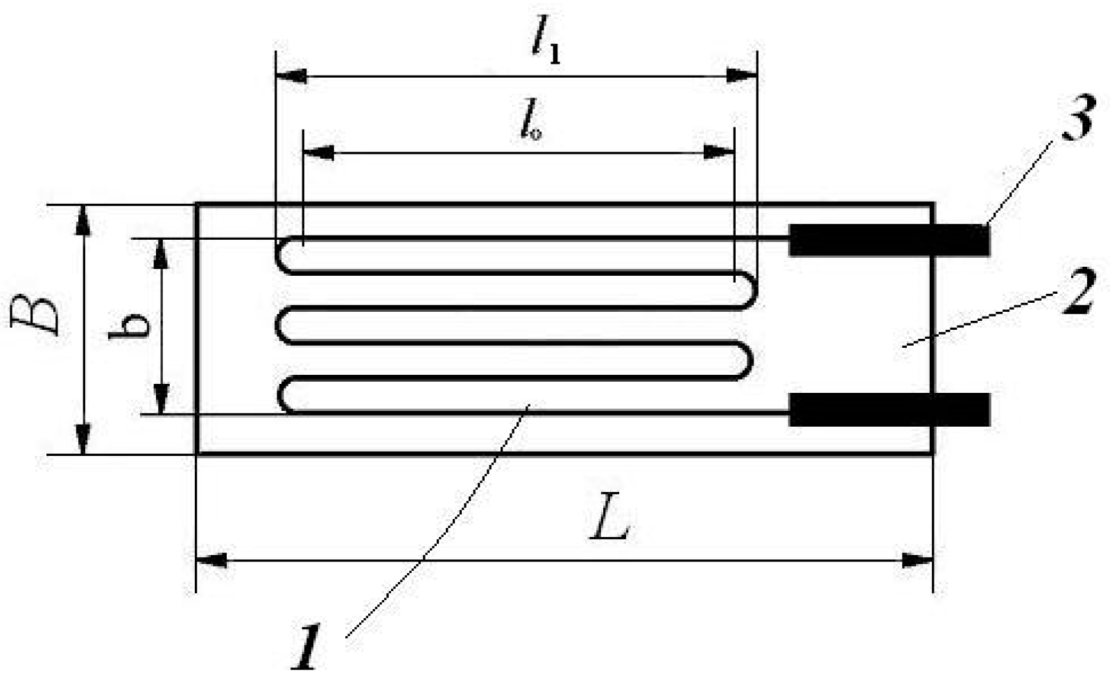
Figure 1. A bonded-wire strain gauge: L—the total length of the gauge; B—the total width of the gauge; l 0 —the active length of the wire serpentine without the loop length; l 1 —the length of the wire serpentine; b—the width of the wire serpentine; 1—the strain-sensing element (here: a metal wire); 2—carrier element; 3—terminals for lead wire connections [37,38,39,40,41,42,43].
Prosthesis 07 00126 g001
Figure 2. Different types of X-rosettes [38,39].
Prosthesis 07 00126 g002
Figure 3. Different technical solutions for three-element rosettes [38,39].
Prosthesis 07 00126 g003
Figure 4. The Fresnel holographic montage: (a) exposure; (b) hologram reconstruction [40,42,50,51].
Prosthesis 07 00126 g004
Figure 5. The principle setup of the ESPI/Shearography system: 1-object, 2,3-laser diodes, 4-CCD camera, 5-interferometer, 6,7-polycarbonate rods [42].
Prosthesis 07 00126 g005
Figure 6. The optical setup of ESPI/Shearography systems [55].
Prosthesis 07 00126 g006
Figure 7. The principle schema of a VIC/DIC 3D system: 1,2-cameras, 3-rigid aluminum bar, 4-stable tripod [58].
Prosthesis 07 00126 g007
Figure 8. The principle of measurement [42,56,57,58].
Prosthesis 07 00126 g008
Figure 9. The original ESG testing bench: (a) assembled testing bench; (b) layout of lamellas with SGs; (c) view along the direction of lamellas B–D; (d) wire loop in the shape of an „8″ [59].
Prosthesis 07 00126 g009
Figure 10. Average relative linear displacement values ∆ [59].
Prosthesis 07 00126 g010
Figure 11. Relative angular displacement values for AC [59].
Prosthesis 07 00126 g011
Figure 12. Relative angular displacement values for DB [59].
Prosthesis 07 00126 g012
Figure 13. Elastic fixation with internal elastic nails; the arrows indicate the fracture direction [60].
Prosthesis 07 00126 g013
Figure 14. Elastic fixation with internal elastic nails, combined with an 8-shaped thin wire loop; the arrows indicate the fracture direction [60].
Prosthesis 07 00126 g014
Figure 15. Elastic fixation combined with a one-sided external fixator; the arrows indicate the fracture direction [60].
Prosthesis 07 00126 g015
Figure 16. Average relative linear displacement values ∆ [60].
Prosthesis 07 00126 g016
Figure 17. Relative angular displacement values along AC [60].
Prosthesis 07 00126 g017
Figure 18. Relative angular displacement values along DB [60].
Prosthesis 07 00126 g018
Figure 19. The principal evaluation schema: (a) the cross-section of a bone with the proposed main directions; (be) different bone fixation cases [63].
Prosthesis 07 00126 g019
Figure 20. Use of conventional DCP plates on: (a) a preserved human femur; (b) a fresh bovine femur [64].
Prosthesis 07 00126 g020
Figure 21. Selection of representative points for different types of fractures: (I) simple unstable fracture with internal fixators; (II) multiple unstable fractures with internal fixators; (III) simple unstable fracture with a DCP plate (external fixator) [64].
Prosthesis 07 00126 g021
Figure 22. Test bench accuracy calculation schemes (a) dimensions of the piston; (b) eccentricity of force F.
Prosthesis 07 00126 g022
Figure 23. Special actuator part.
Prosthesis 07 00126 g023
Figure 24. Original ESG displacement sensor: (a,b) the level of the bores.
Prosthesis 07 00126 g024
Figure 25. Calibration bench: 1—support base; 2—support column; 3—micrometer support arm; 4—fixing screw; 5—lamella with ESGs; 6—aluminum lamella support; 7—connecting piece; 8—micrometer class 0.1: A and B the level of the bores.
Prosthesis 07 00126 g025
Figure 26. Calibration curve for lamella #2.
Prosthesis 07 00126 g026
Figure 27. Upper subassembly: 1—special actuator part; 2—cylinder liner; 3—piston with three segments; 4—rigid cylinder liner fixing ring; 5—M14 fixing screws.
Prosthesis 07 00126 g027
Figure 28. General assembly of the test bench: 1—special actuator part; 2—cylinder liner; 3—piston with three segments; 4—rigid cylinder liner fixing ring; 5—M14 fixing screws; 6—bone under test; 7—rigid fixing columns; 8—columns for adjustable (height) fixing of the displacement sensors; 9—subassembly of the displacement sensors; 10—rigid support plate; 11—cup for fixing the lower end of the bone.
Prosthesis 07 00126 g028
Table 1. Results in the case of the analyzed bovine femur [64].
Type of FixatorLinear Strain
ε x at Point j
Linear Strain
ε y at Point j
ε x 1 ε x 2 ε x 3 ε y 1 ε y 2 ε y 3
DCP plate0.00030.00200.02230.06000.1320−0.3290
Bridge plate−0.00100.01490.02370.0283−0.0199−0.0213
Disclaimer/Publisher’s Note: The statements, opinions and data contained in all publications are solely those of the individual author(s) and contributor(s) and not of MDPI and/or the editor(s). MDPI and/or the editor(s) disclaim responsibility for any injury to people or property resulting from any ideas, methods, instructions or products referred to in the content.