1. Introduction
Limb loss is a significant cause of disability arising from diverse factors such as trauma, conflicts, diabetes, or peripheral vascular disease. Prostheses play a crucial role in enhancing the quality of life for amputees by restoring functionality and improving mental and social well-being [
1]. A lower-limb prosthesis typically consists of three key components: a socket, a pylon, and a foot. Among these, the socket, resembling a cup in structure, is pivotal for load transmission, enabling a natural walking motion with adequate control and stability [
2].
Crafting a custom-made socket for a prosthetic limb typically initiates obtaining a negative mould of the residual limb. Conventional methods include the Patellar Tendon Bearing (PTB) casting technique, where a negative mould of the limb is formed using a plaster cast [
3,
4]. Subsequently, a positive mould is meticulously adjusted to accommodate the individual’s bony prominences and sensitive areas. Despite its reliability, PTB requires the expertise of skilled prosthetists. In response to its challenges, the Total Surface Bearing (TSB) method was developed to distribute pressure uniformly across the stump’s surface, reducing the risk of discomfort, pressure sores, and skin breakdown. Additionally, techniques such as hydrostatic pressure casting employ fluid to achieve uniform pressure across the residual limb [
5,
6,
7,
8,
9]. Modern CAD/CAM technology has also been utilised to create a consistent residuum cast by capturing the limb’s shape and refining it using 3D modelling software [
10,
11].
A comprehensive review was conducted to categorise state-of-the-art technologies involved in socket design.
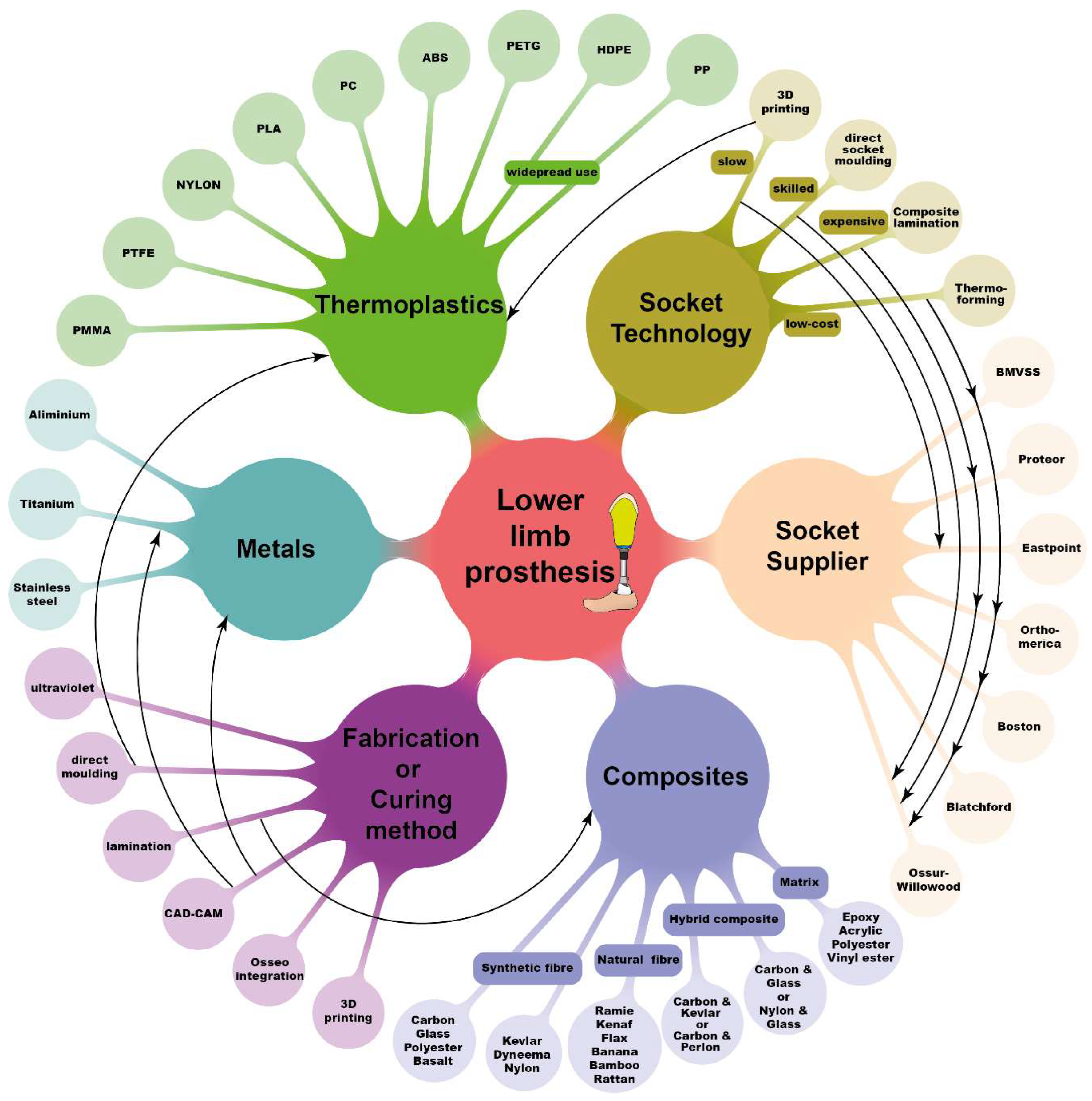
Figure 1 illustrates socket materials, manufacturing techniques, and major companies currently engaged in lower-limb prosthesis production. Thermoplastic polymers like polypropylene (PP) and high-density polyethylene (HDPE) are commonly used as socket materials, particularly in less-resourced nations, due to their affordability, availability, and ease of manufacturing [
12]. High-performance fibres, such as carbon, glass, or Kevlar embedded within a thermosetting polymer-based matrix, offer superior strength and stiffness. Studies have also explored the use of natural or recycled materials for prosthetic socket fabrication, including renewable plant oil resin with plant fibre composites and sustainable reinforcement fibres like jute, flax, and pineapple fibre [
1,
13,
14]. Additive manufacturing has facilitated the production of prosthetic sockets with controlled weight [
15,
16].
The selection of materials and manufacturing techniques for prosthetic sockets is influenced by factors such as resource availability, cost concerns, and the economic circumstances of individual countries. Thermoforming and composite lamination are widely used methods for socket fabrication. Thermoforming entails heating a thermoplastic sheet to a semi-molten state and draping it over the male casting model. For instance, Bhagwan Mahaveer Viklang Sahayata Samiti (BMVSS), an Indian not-for-profit organisation providing rehabilitation services in 26 countries, employs this method to fabricate transtibial and transfemoral sockets using high-density polyethylene material [
17,
18]. However, this process necessitates multiple clinic visits due to potential inconsistencies. Conversely, the composite lamination socket manufacturing technique was developed to produce high-performance sockets by reinforcing synthetic fibres like carbon, glass, or Kevlar with virgin polymer [
19,
20]. Composite prosthetic sockets offer greater strength and stiffness than monolithic thermoplastics. Hybrid fibres have gained traction due to their distinct individual properties, yielding highly functional prosthetic sockets. Notwithstanding these synthetic fibres, numerous studies have explored the use of natural fibres or a blend of natural and synthetic fibres [
21,
22,
23].
With advancements in additive manufacturing (AM), numerous studies and companies have leveraged this technique for socket fabrication. Despite the potential of 3D-printed sockets, additional post-processing techniques are necessary to achieve the required strength and structural integrity [
16,
24]. Additionally, ISO 10328 socket testing is widely employed to evaluate the structural integrity of sockets under various loading conditions, including front foot and heel strike [
16,
25].
In this context, self-reinforced polymers (SRPs) were explored as candidate materials for prosthetic sockets. SRPs offer high material performance with minimal density, holding promise for environmental conservation [
26]. Commercially available SRPs include poly(ethylene terephthalate) (PET), poly(methyl methacrylate) (PMMA), poly(lactic acid) (PLA), polyamide 6 (PA6), and polypropylene (PP) [
27,
28,
29,
30,
31,
32]. Among these materials, srPLA stands out for its biodegradability advantages, while srPET boasts recyclability due to abundant post-consumer waste streams such as PET water bottles and other food packaging systems [
28,
33,
34].
This study aims to develop cost-effective manufacturing processes for creating high performance prosthetic sockets using single-polymer composite (SPC) and dual-polymer composite (DPC). PLA and PET materials were used for SPC, while glass fibre (GF) and carbon fibre (CF) were incorporated into a low-tenacity PET matrix for DPC. The study is structured as follows: Firstly, we outline the methods for manufacturing laminate material and prosthetic sockets. Secondly, we describe the testing process employed to assess socket strength. Thirdly, we compare the mechanical properties of SPC and DPC composites, followed by a comparative analysis of the structural responses of SPC and DPC sockets against traditional prosthetic sockets. Finally, we mention the fabrication of patient-specific sockets using srPET and evaluate socket performance through clinical trials.
2. Method
2.1. Ethical Considerations
The study protocol underwent rigorous scrutiny and received approval from the De Montfort University Ethical Review Committee (Research Ethics Application Approval: 1920/553). Before participation, all subjects provided informed consent, encompassing the publication of photographs and data on their use of prosthetic sockets.
2.2. Materials
PLA and PET fibres were meticulously chosen based on their distinct melting temperatures to develop commingled yarn, subsequently employed in producing 2/2 twill woven fabric by COMFIL APS
®, Gjern, Denmark. These woven fabrics served as the foundation for creating Single Polymer Composites (SPCs) and Dual Polymer Composites (DPCs), denoted as SPLA, SPET, DCF, and DGF.
Table 1 outlines the primary constituents of each yarn utilized in woven fabric production. SPLA yarn comprises low-melting LPLA fibres as a matrix and high-temperature HPLA fibres as reinforcement, rendering it 100% bio-plastic. SPET yarn, 100% recyclable, incorporates low-melting LPET fibres as a matrix and high-tenacity HPET fibres as reinforcement. DCF and DGF composites employ LPET fibres as the matrix, with Carbon fibres (Carbon 12 K) and Glass fibres (E-Glass) serving as reinforcement. The reinforcement diameter of SPLA, SPET, DGF, and DCF are 16.2 µm, 20.8 µm, 13.84 µm, and 5.3 µm, respectively.
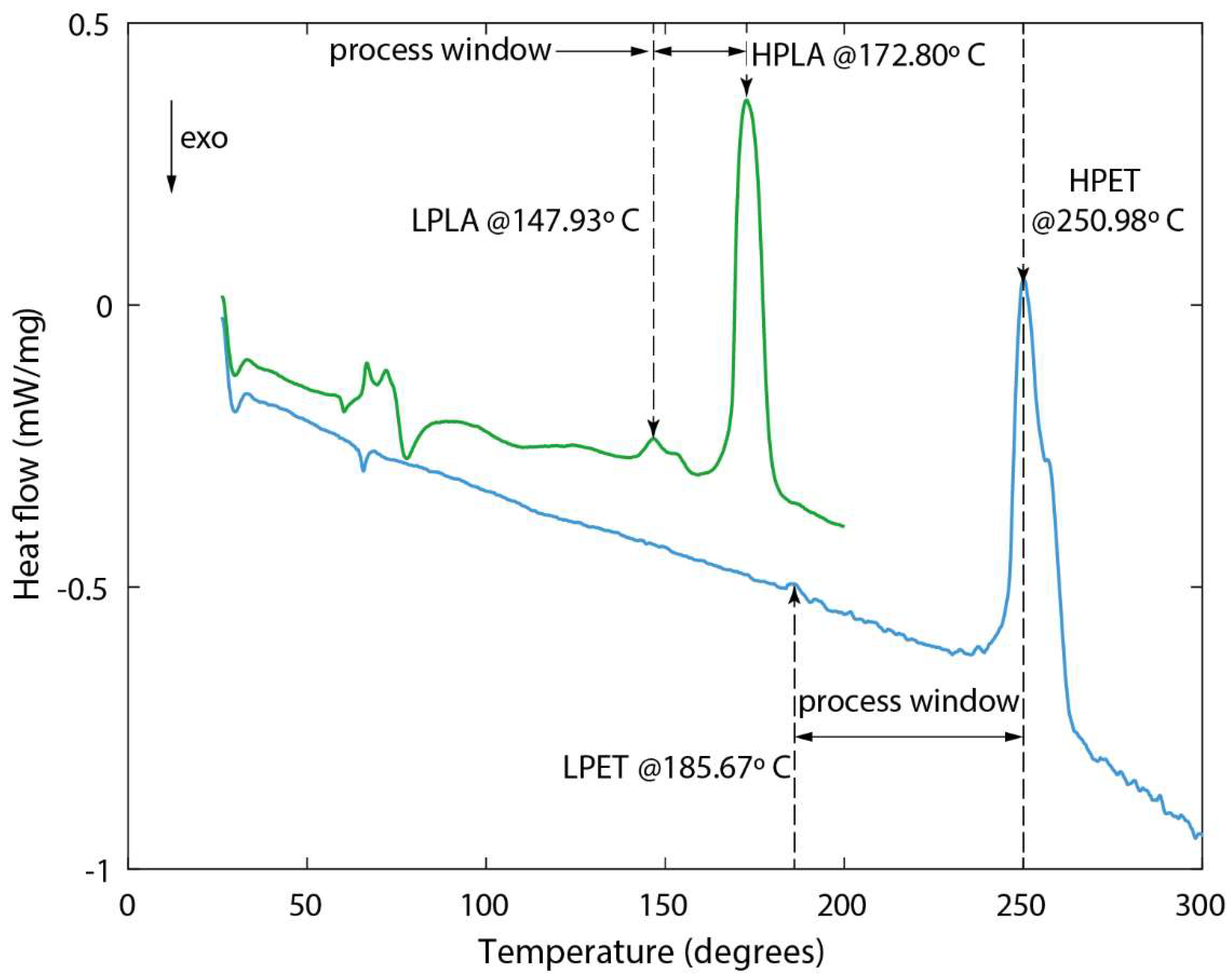
Figure 2 illustrates the thermogram of commingled SPLA and SPET yarn samples obtained using DSC-Netzsch DSC 214 polymer equipment. Each commingled yarn sample, weighing 3 mg, was placed in a Concavus aluminium crucible and heated at 20 °C/min. Both SPLA and SPET samples exhibited two peaks, indicative of the melting of the matrix and reinforcement fibres, as depicted in
Figure 2. Accurate identification of these peaks is crucial in determining the process window for consolidating composite laminates and prosthetic sockets. SPLA demonstrates a narrow process window of 24.87 °C, whereas SPET boasts a broader process window of 65.31 °C without compromising the integrity of the reinforcement fibres.
During the manufacturing process, EZ-Brush™ Vac Bag Silicone and Ease Release™ 200 Aerosol spray from Bentley Chemicals Ltd. in Worcestershire, UK, were employed to produce a Reusable Vacuum Bag (RVB) and a releasing agent, respectively. A high-temperature aerosol spray adhesive was utilized to secure the edges of the woven fabric during socket fabrication.
2.3. Manufacturing and Mechanical Testing of SPC and DPC Laminates
Vacuum-Assisted Consolidation (VAC) at elevated temperatures was employed to fabricate SPC and DPC composites. Initially, a dry 2/2 Twill woven fabric was trimmed to dimensions of 400 mm × 400 mm, and six layers were stacked together. These stacked layers underwent a drying process in an oven set at 50 °C for 24 h to ensure optimal moisture content. Subsequently, the surface of an aluminium plate was meticulously cleaned with Acetone, followed by the application of Ease Release™ 200 Aerosol spray to facilitate easy release of the laminate. The dried woven fabric was then positioned atop the plate, enveloped within an envelope-type vacuum bag, and introduced into an Infrared Red-type heating autoclave for composite laminate consolidation.
Maintaining an internal vacuum level of 85%, the exterior of the vacuum bag was heated at a rate of 5 °C per minute until reaching consolidation temperatures of 155 °C, 200 °C, 220 °C, and 220 °C for SPLA, SPET, DCF, and DGF composites, respectively. The selection of consolidation temperatures exceeding the matrix melting temperature for each composite ensured optimal wetting of the melted matrix with reinforcement fibres. Each composite laminate underwent curing at its designated consolidation temperature for 20 min. Post-curing, the plates were gradually cooled at a rate of 5 °C per minute until reaching 100 °C before removal from the autoclave for sample preparation. This controlled cooling process helped maintain the structural integrity and stability of the specimens. To ensure uniformity and accuracy, each composite laminate was manufactured using VAC with different consolidation temperatures, as described earlier.
For mechanical testing, dog-bone-shaped specimens were cut from the laminates using an Epilog laser cutter following ASTM D638 standard specifications. Specimen edges were polished with sandpaper to minimize stress concentration and premature failure. Tensile testing was conducted utilizing the Instron 3369 Universal Testing Machine, with a tension rate of 1 mm per minute until specimen failure. An external strain clip gauge was mounted within the gauge section of each specimen to accurately measure strain. The force-displacement response of the laminates was recorded during testing, enabling the calculation of engineering stress and strain. Quality control measures, including regular calibration of testing equipment and verification of test results through repeated trials, were implemented to ensure the reliability and repeatability of mechanical testing data.
2.4. Fabrication of Reusable Vacuum Bag (RVB)
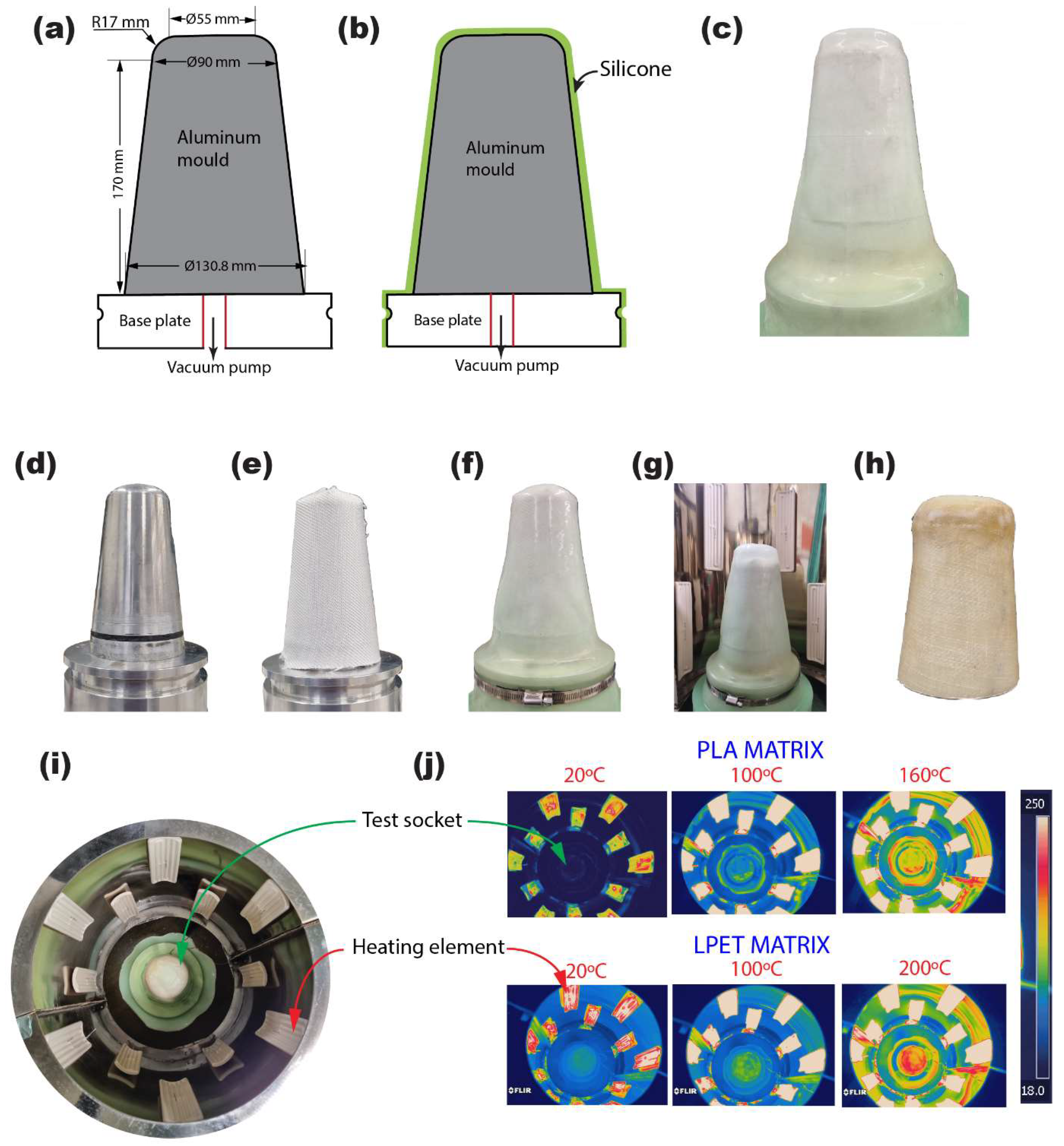
Utilizing precision CNC machining, an aluminium block was meticulously carved based on the design outlined in
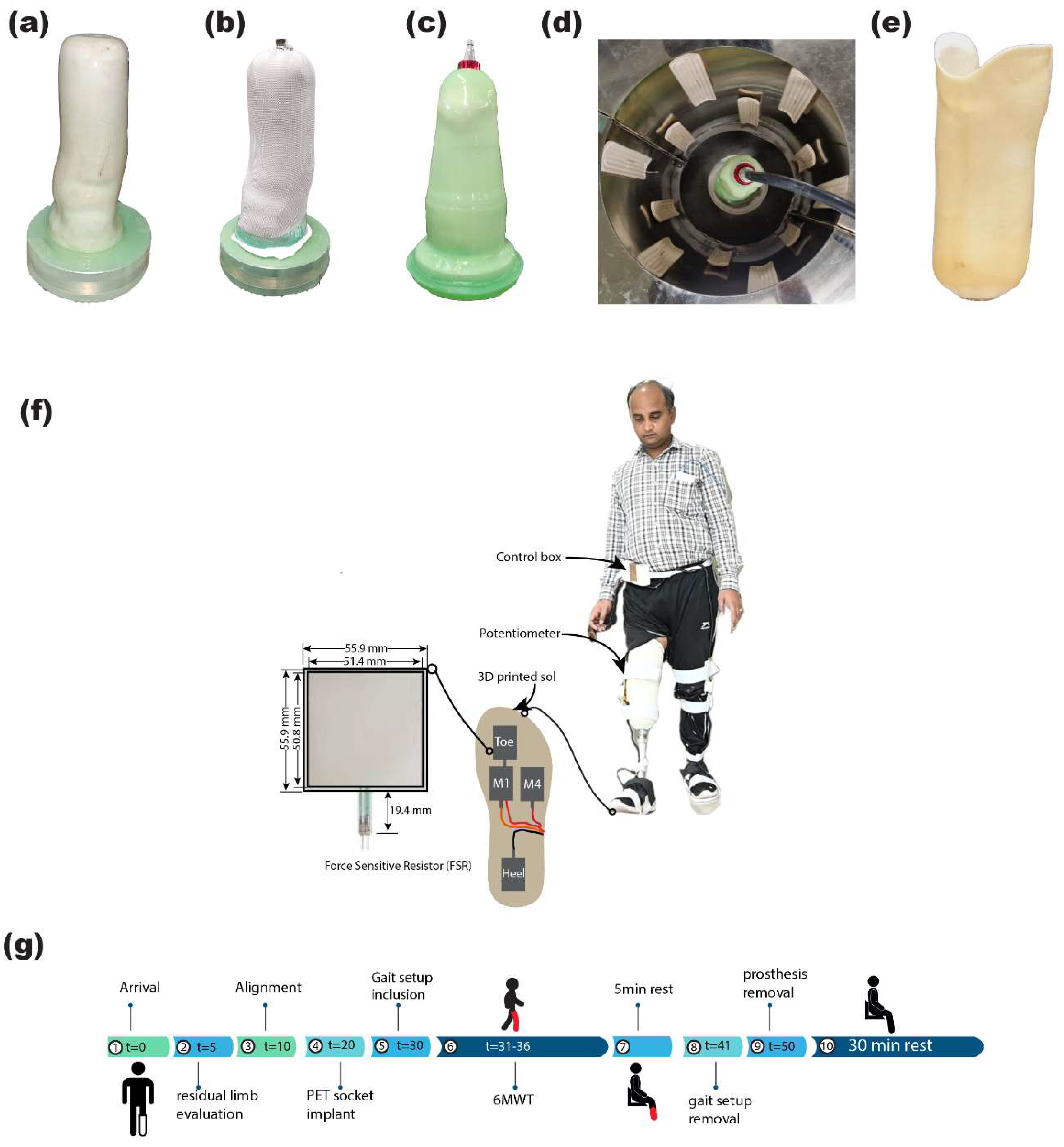
Figure 3, resulting in the creation of a socket mould and vacuum plate. The integration of the vacuum plate and socket mould, depicted in
Figure 3b, constituted the formation of the RVB essential for socket manufacturing.
To ensure optimal adhesion and release properties, the assembled components underwent thorough cleaning with Acetone followed by the application of Ease Release™ 200 Aerosol spray across their surfaces. Subsequently, a precisely measured quantity of 450 g each of part A and part B was combined to produce a total of 900 g of the two-part EZ~Brush™ Vac Bag Silicone resin. To eliminate any potential presence of trapped air within the mixture, it was subjected to a degassing process under vacuum conditions. The degassed silicone resin was then carefully poured over the mould, allowing it to uniformly cover the surfaces under the influence of gravity. Following a curing duration of 30 min, the RVB was delicately removed from the mould. Notably, the resultant RVB exhibited identical contours to the socket assembly, boasting a consistent wall thickness of 2 mm throughout its structure.
2.5. Fabrication and Structural Testing of ISO Socket
The initial phase involved thorough cleaning of the vacuum plate, socket mould, and reusable vacuum bag (RVB) using Acetone, ensuring pristine surfaces essential for socket manufacturing. Subsequently, Ease Release™ 200 Aerosol spray was uniformly applied to these components at each stage, facilitating easy release and preventing potential adhesion issues. Crucial components in socket construction, the woven fabrics, underwent a meticulous drying process at 50 °C for 24 h, eliminating any residual moisture that could compromise structural integrity. Once dried, the fabrics were precisely trimmed to fit the socket’s geometry and carefully wrapped around the mould as per predetermined design specifications. To ensure secure adhesion and prevent unravelling, aerosol spray adhesive was judiciously applied to the material edges, critical for maintaining structural integrity during consolidation.
The assembly, comprising wrapped fabric layers and the socket mould, was then enclosed within the RVB, acting as a protective barrier during consolidation. Transported to a specially designed circular autoclave (refer to
Figure 3), the assembly underwent consolidation under controlled conditions.
Equipped with eight 500 W ceramic infrared heating elements mounted along its circumference, the autoclave ensured uniform heating of the mould assembly’s surface, maintaining consistent consolidation temperatures. Temperature profiles for SPC and DPC consolidation, programmed into the autoclave’s PID controller, mirrored those employed during laminate fabrication.
The effectiveness of the consolidation process was validated through thermogram images captured during elevated temperature cycles, demonstrating uniform heat distribution across the mould assembly’s surface.
Adhering to a consistent manufacturing protocol, both SPC and DPC composite sockets were meticulously crafted, varying only in the number of layers. SPCs (SPLA and SPET variants) were composed of three, six, or nine layers, while DPCs (DCF and DGF variants) incorporated two, three, or six layers, tailored to specific design and structural requirements.
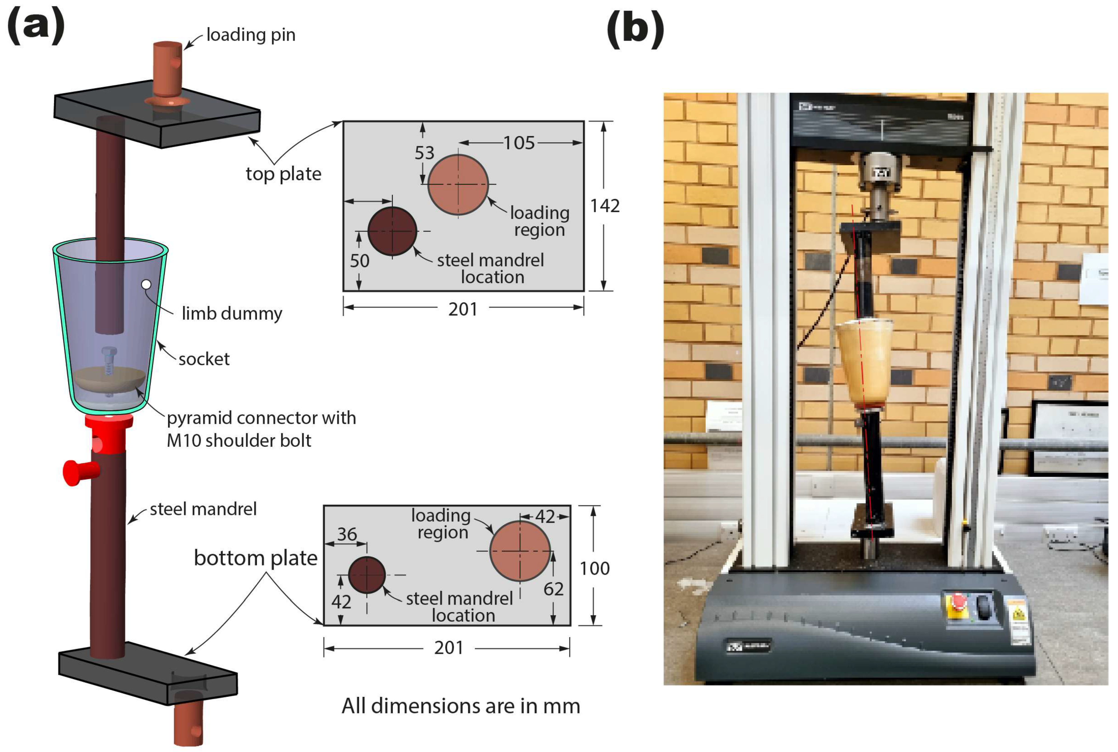
To determine socket ultimate strength, ISO 10328 standards were adhered. A custom rig made of hardened steel was utilized, with load application points on both bottom and top platens, machined at specific offset distances from steel mandrels connecting the socket.
Figure 4a depicts alignment setup for assembling the socket’s test rig. Initially, a 10 mm hole was drilled in the check socket’s distal end for mounting a single-hole pyramid connector. Plaster of Paris (PoP) slurry was then used to create a limb dummy, with the top steel arm inserted into the check socket using a bench alignment rig and left for at least 24 h before testing.
Tests were conducted using an Instron 3369 universal testing machine with a 25 KN load cell, applying load to the socket sample at a rate of 100 cap N/s until failure or reaching a maximum load of 6000 cap N. Socket failure was determined as the point beyond which it could not support any increasing load.
The study involved testing 36 sockets, with three tested for each material and thickness. Accuracy was ensured by creating a new limb dummy for each test using PoP and integrating new socket connectors to directly compare performance.
2.6. Fabrication and Evaluation of Patient-Specific Socket
Upon evaluating the strengths of the SPC sockets, the SPET socket was selected for manufacturing patient sockets due to its superior strength compared to the SPLA socket. The objective was to create a prosthetic socket tailored to each patient using the Patella-Tendon Bearing method.
The fabrication process commenced by wrapping cling film around the residual limb to create a mould, capturing pressure-sensitive and pressure-tolerant areas. A wet PoP bandage was then applied to form a negative cast, accurately replicating the limb’s shape. Skilled prosthetists modified the positive cast based on a typical standard marking protocol, ensuring optimal weight distribution and comfort for the amputees (see
Figure 5a).
Similar to the preparation of test sockets, patient-specific casts underwent drying in an oven at 200 °C for one hour to eliminate moisture content. Meanwhile, six layers of woven PET fabric were dried at 50 °C for 24 h, following the same process as PET laminates or ISO sockets.
To prevent any chemical reaction between the cast and resin, thin RVBs were used to isolate the cast from the central arrangement. The fabric was wrapped over the cast in layers, with the pyramid-type connector placed at the distal end’s top. Aerosol spray adhesive was applied to securely bond the edges of each fabric layer. A tight RVB was then drawn over the fabric to prevent wrinkling and unravelling. Finally, the primary RVB was placed over the entire arrangement and firmly secured with stainless steel pipe clamps.
The complete setup was transferred to an autoclave, where the temperature profile from the test socket curing was followed to solidify the patient-specific socket. Identical manufacturing processes were employed for all seven patient-specific sockets for unilateral amputees.
To evaluate the performance of the patient socket, the widely adopted Six-Minute Walking Test (6MWT) was used to assess the walking ability of unilateral amputees with PET sockets. Prior to the test, participants received comprehensive written and verbal explanations of the protocol. Precautionary measures were taken to ensure the trial’s safety, including careful examination of residual limbs for any wounds or blisters, and thorough inspection of the socket, pylon, and foot alignment using the Laser posture instrument.
During the 6MWT protocol, patients walked for 6 min along a 12 m-long hallway marked with cones, wearing Jaipur foot prosthetics. The wearable gait setup device, consisting of two wearable footbeds with Force Sensitive Resistors (FSR) and a burster potentiometer to assess force and knee flexion angle relative to the hip, was attached to the participants’ legs using Velcro or adhesive straps [
35]. Data on vertical GRF from each FSR and sagittal knee flexion angle from each leg were extracted using a controller box, enabling the analysis of gait performance. All amputees completed the 6MWT without experiencing any interruptions or pain.
3. Result
3.1. Structure of SPC and DPC Laminates
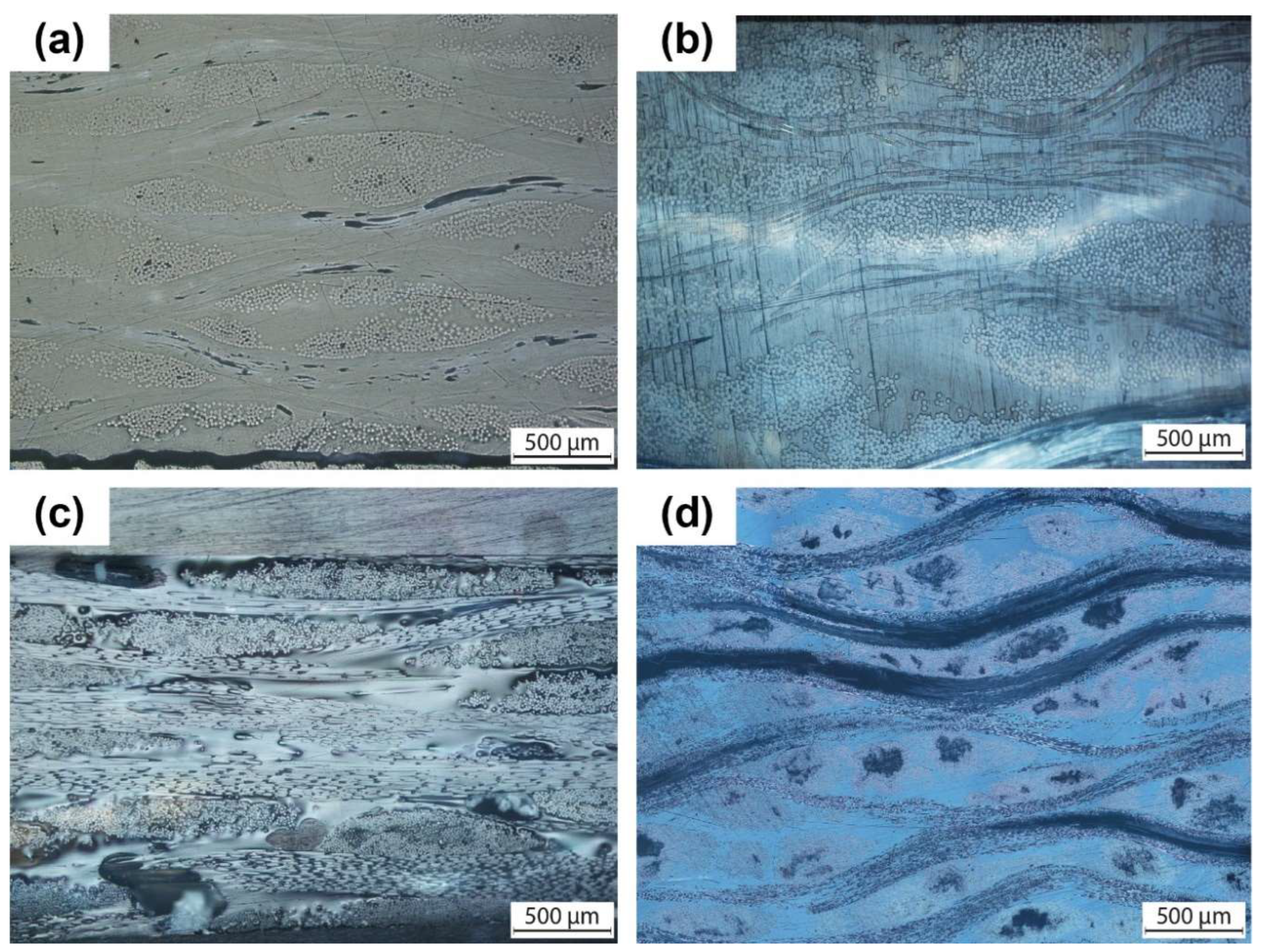
Figure 6 presents an optical microscopy image offering insight into the cross-section of both Single-Polymer Composite (SPC) and Dual-Polymer Composite (DPC) laminates. This visual reveals the presence of two distinct phases within the laminates: the matrix and the reinforcement fibres. Employing a vacuum-assisted consolidation (VAC) process coupled with carefully selected consolidation temperatures, we ensured the preservation of the original shape of the reinforcement fibres. As a result, the matrix fibres underwent melting, leading to the formation of a homogeneous monolithic medium that encapsulates the reinforcement fibres effectively. Furthermore, meticulous attention to the consolidation process facilitated optimal bonding of all stacked layers, contributing to a uniform distribution of reinforcing fibres throughout each laminate. This structural integrity is crucial for enhancing the overall mechanical properties and performance of the prosthetic sockets.
3.2. Mechanical Response of the SPC and DPC Composites
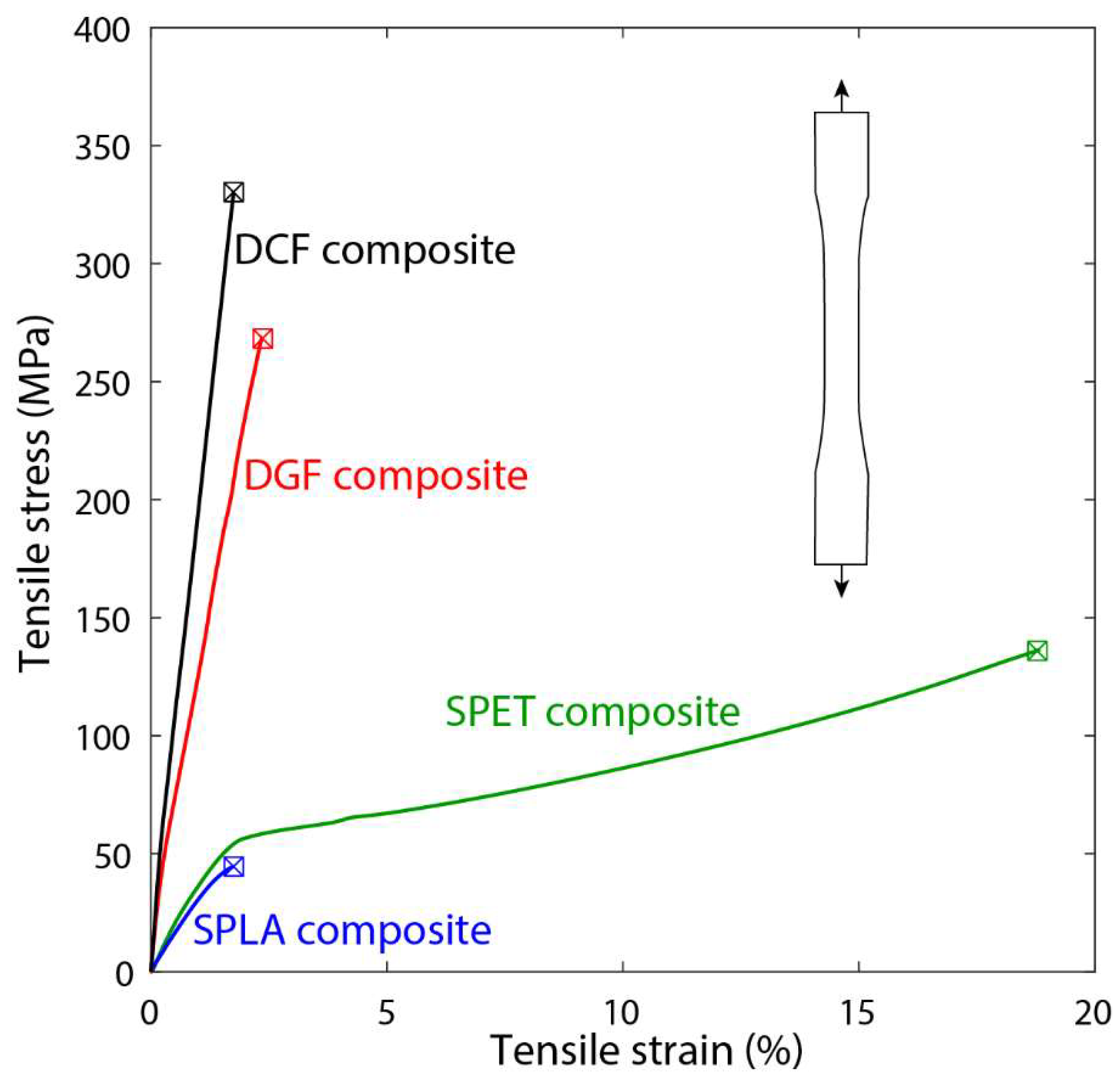
In
Figure 7, the tensile response of both SPC and DPC composites is illustrated through the mechanical testing of laminated dog-bone specimens. The SPLA composite exhibited an elastic-brittle failure mode, characterized by an average strain of 2% in both longitudinal and transverse directions. In contrast, SPET displayed an elastic-plastic response, showcasing a yield strength of 56 MPa and a failure strain of 20%. Remarkably, the yield strength of SPET was consistently defined in both directions at 56 MPa, indicating its robust mechanical properties compared to SPLA.
The DGF and DCF composites demonstrated superior mechanical characteristics, including high strength, modulus, and reduced average strain compared to SPLA and SPET. The DPCs (GF and CF) exhibited an elastic-brittle response predominantly governed by the reinforcing fibres, indicative of their structural integrity and reinforcement efficiency. A comprehensive summary of the critical mechanical properties of the SPC and DPC composite laminates is presented in
Table 2.
Specifically, the DCF composite samples exhibited the highest Young’s modulus (28.3 GPa) and ultimate tensile strength (358.5 MPa) along the warp direction, highlighting their exceptional mechanical performance. Furthermore, the ranking of Young’s modulus across the SPC and DPC composites, as outlined in
Table 2, follows the order: srCF > srGF > srPET > srPLA. Notably, SPET demonstrated a significantly higher failure strain compared to all materials under investigation, indicating its enhanced ductility and resilience under tensile loading conditions.
3.3. Structural Response Analysis of SPC Sockets
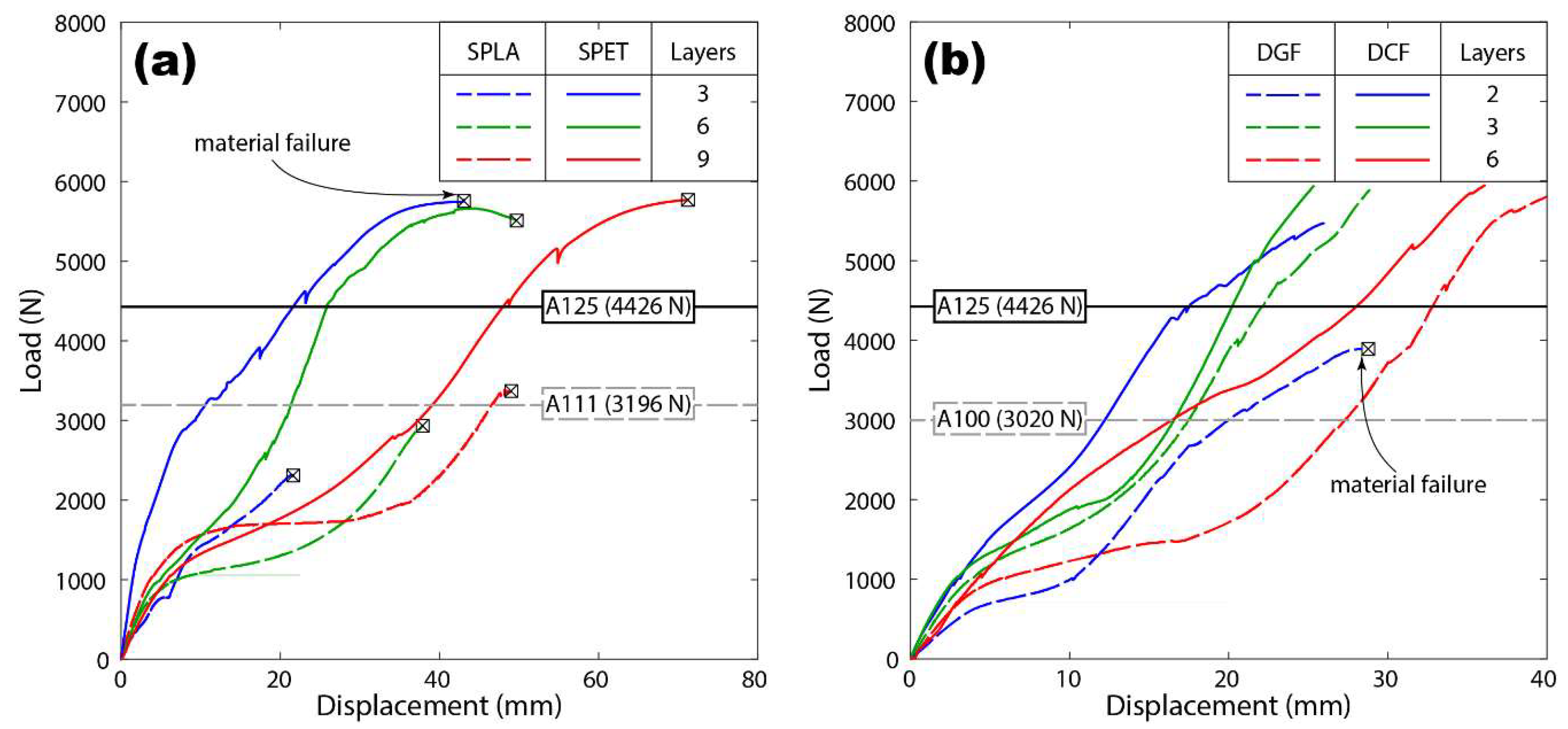
The compressive response of the SPC prosthetic sockets was analysed, as depicted in
Figure 8a. Initially, the load exhibited a linear increase with displacement during the initial loading phase, indicative of an elastic response. Subsequently, the sockets demonstrated a softening response, where further loading resulted in a reduction in stiffness. This softening behaviour transitioned into a hardening response under increased loading conditions, although in some cases this phase led to socket failure.
Remarkably, SPLA sockets displayed varying degrees of mechanical integrity during testing. With the exception of SPLA9L, all SPLA sockets suffered fractures during the loading process. SPLA9L, however, surpassed the loading criterion of 3020 N, exhibiting a typical ductile response characterized by a yield strength of 1800 N and a maximum displacement of 52 mm.
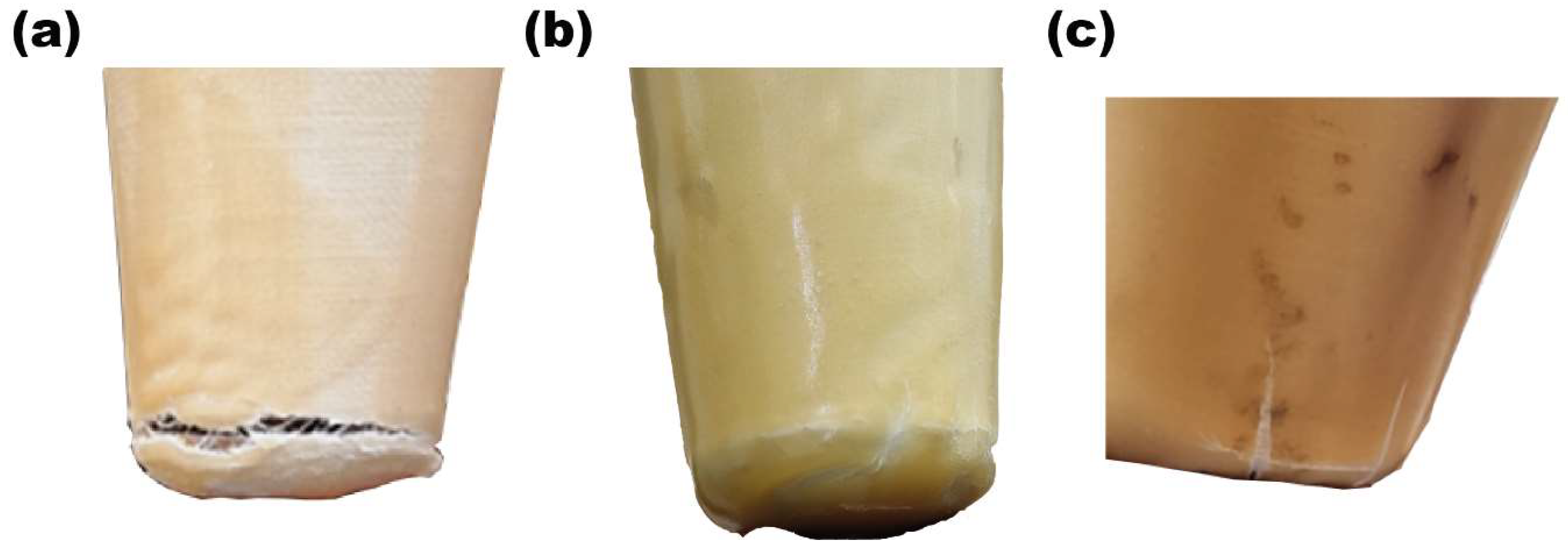
Figure 9 provides insight into the material failure observed at the distal end of the SPLA socket. The failure mechanism initiated at the distal end and propagated circumferentially around the socket, with some instances showing the presence of vertical cracks. Notably, the material failure process exhibited a prolonged duration, suggesting a complex failure mode.
All SPET sockets exhibited exceptional mechanical performance, surpassing the loading criterion of 4025 N. SPET3L and SPET6L failed at loads of 5686 N and 5781 N, respectively, while SPET9L withstood the maximum load of 6000 N. Interestingly, SPET sockets displayed a ductile response, with higher displacements of 40 mm and 72 mm observed for six and nine layers of SPET sockets, respectively.
Furthermore, the strength of all SPC sockets at different load profiles, including A100, A111, and A125, was assessed (refer to
Figure 8a). These loading levels were based on locomotion data acquired during the development of ISO 10328, with A111 and A125 extrapolated from simulation and field observation. The results indicate that SPET sockets exhibited high reliability across all loading conditions.
While sockets made from three and six layers of SPET surpassed the upper limit of the loading criterion for the high associated level of A125, SPET9L demonstrated resilience by withstanding a load of 6000 N. However, further optimization of layer configurations may be required to meet the ISO strength requirement. Conversely, SPLA sockets exhibited significantly lower maximum strength levels, with the 9-layer SPLA socket withstanding a maximum load of 3200 N.
Based on these findings, it can be concluded that SPET sockets offer a more reliable and durable option across various loading conditions, highlighting their potential as superior prosthetic socket materials.
3.4. Structural Response Analysis of DPC Sockets
Figure 8b illustrates the structural response of DPC sockets during ISO strength testing, presenting a load versus displacement profile akin to that observed for SPC sockets under compression loading. However, notable differences emerged, particularly in the stiffness of DPC sockets fabricated from DGF and DCF materials compared to those made from SPLA and SPET.
Observations revealed that DCF and DGF sockets exhibited greater stiffness, primarily influenced by the reinforcing fibres rather than the PET matrix. Despite passing the P5 loading condition threshold, DCF2L, DGF3L, and DGF2L sockets failed to reach the 6000 N mark due to material-related failures as the load decreased beyond the maximum strength.
However, DGF2L and DGF3L sockets reached maximum loads of 4016 N and 4717 N, respectively, while the DCF socket withstood all associated load criteria without fracture. The homogeneous mechanical properties of DCF rendered it a suitable material for definitive sockets for amputees. It is noteworthy that the standard DCF socket fabrication with thermosetting resin failed to reheat for reshaping based on the socket’s contours. Nevertheless, the fabrication process demonstrated with SPC and DPC thermoplastic sockets underscores its feasibility and prudence.
Our study underscores the potential of prosthetic sockets crafted from SPC and DPC materials to meet ISO strength requirements while providing a comfortable fit for amputees. However, further research is warranted to determine the optimal number of layers necessary to reduce the socket’s mass and minimize the metabolic energy required for walking. The versatility of SPC and DPC materials allows for customization to accommodate amputees of varying body masses, highlighting their adaptability and potential for widespread application in prosthetic socket design and fabrication.
3.5. Foot Pressure Analysis of Unilateral Amputees
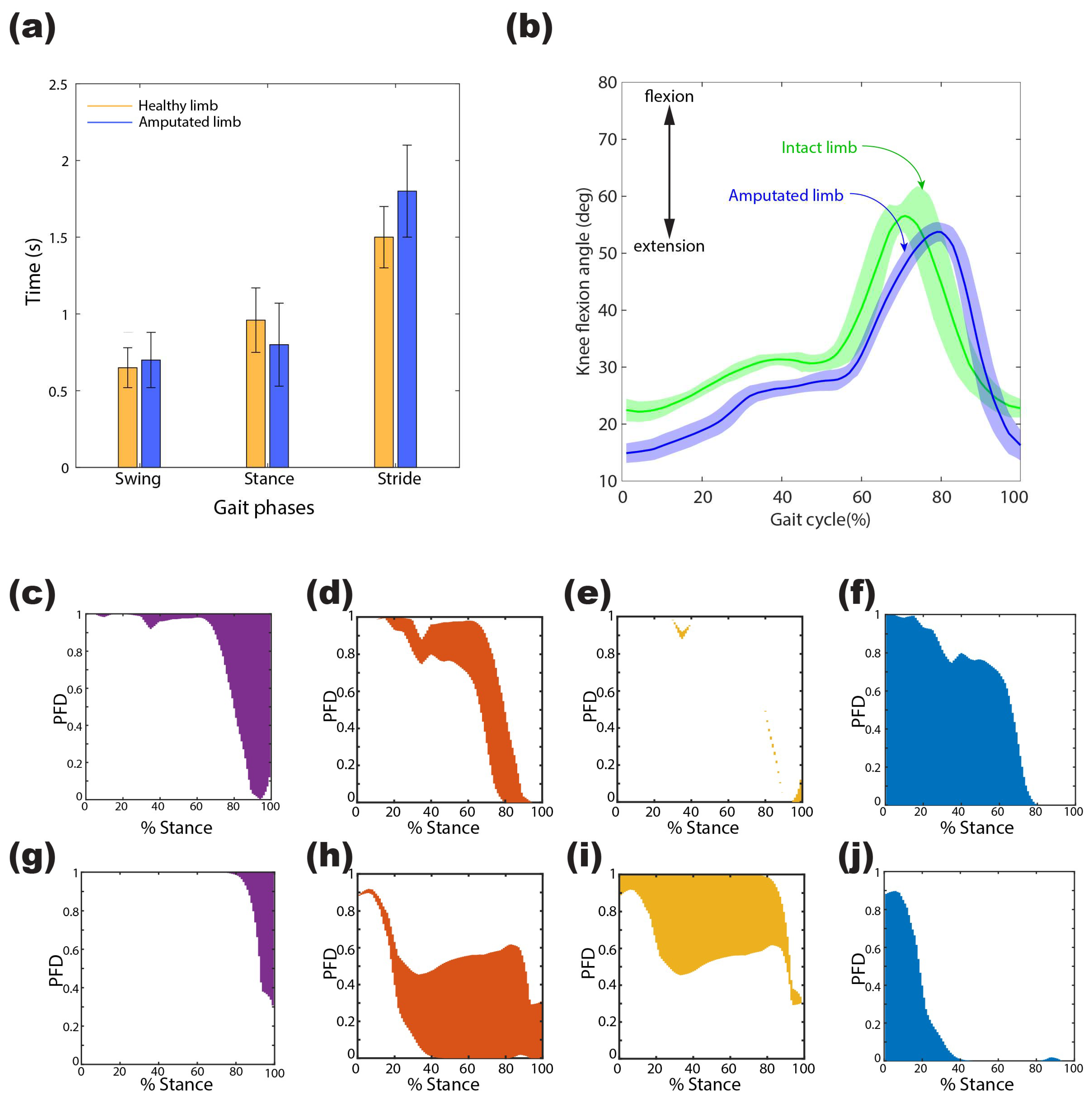
The foot pressure analysis of unilateral amputees involved the extraction and processing of data obtained from a wearable gait setup using MATLAB R2022a (MathWorks, Natick, MA, USA). Participants covered a distance of 196 m with a velocity of 0.5454 m/s and a cadence of 40 steps/min. Analysis of the gait cycle revealed that, on average, the amputated leg spent 60.7% and 39.23% of the cycle in the stance and swing phases, respectively, while the healthy leg exhibited 71.1% and 28.89% in the respective phases, indicating a discrepancy in temporal phasing between the amputated and intact limbs.
During the 6 min walking test (6MWT), the sagittal knee flexion angle of unilateral amputees wearing SPET prostheses was assessed relative to the hip.
Figure 10a,b illustrates the gait phases and knee flexion angle of the amputee during the trial. Despite variations in temporal phasing and amplitude, the angular displacement pattern remained consistent across various locomotion phases. The amputated PET socket limb exhibited a maximum mean angle of 51 degrees and demonstrated a prolonged duration to reach the swing phase. Additionally, slight alterations were observed in the intact limb’s biomechanics when using PET prostheses, highlighting the significant impact of the prosthesis on both intact and amputated limb gait patterns.
The foot pressure analysis included participants who received prostheses as part of the patient-specific socket trial. Seven patients from India, existing users of prostheses, were included in this study, all of whom were still wearing their previous prostheses at the time of inclusion. These participants quantified their current health state and retrospectively compared it with their health state before receiving the new prostheses. Long-term follow-up assessments revealed high levels of satisfaction among the participants, who continued to use the provided sockets consistently.
To analyse pressure distribution and gain insights into pathological conditions, vertical ground reaction force (VGRF) data were collected from each force-sensitive resistor (FSR) at 12 distinct instances throughout the 6MWT, with one datum recorded every 30 s. The percentage contribution of VGRF over the gait’s stance phase, shown in
Figure 10c–j, revealed distinct pressure distribution patterns between the intact and amputated limbs. The intact limb exhibited greater engagement of the heel and toe regions, with minimal participation at the metatarsal 1 region, while the amputated limb relied more on the metatarsal head region, indicating an altered pressure distribution compared to the intact limb.
The analysis underscores the importance of assessing foot pressure distribution in understanding the biomechanical adaptations associated with prosthetic sockets, particularly in optimizing mobility and comfort for amputees. These findings contribute valuable insights into the design and performance of prosthetic sockets, emphasizing the need for personalized and optimized designs to enhance overall gait performance and user satisfaction.
4. Discussion
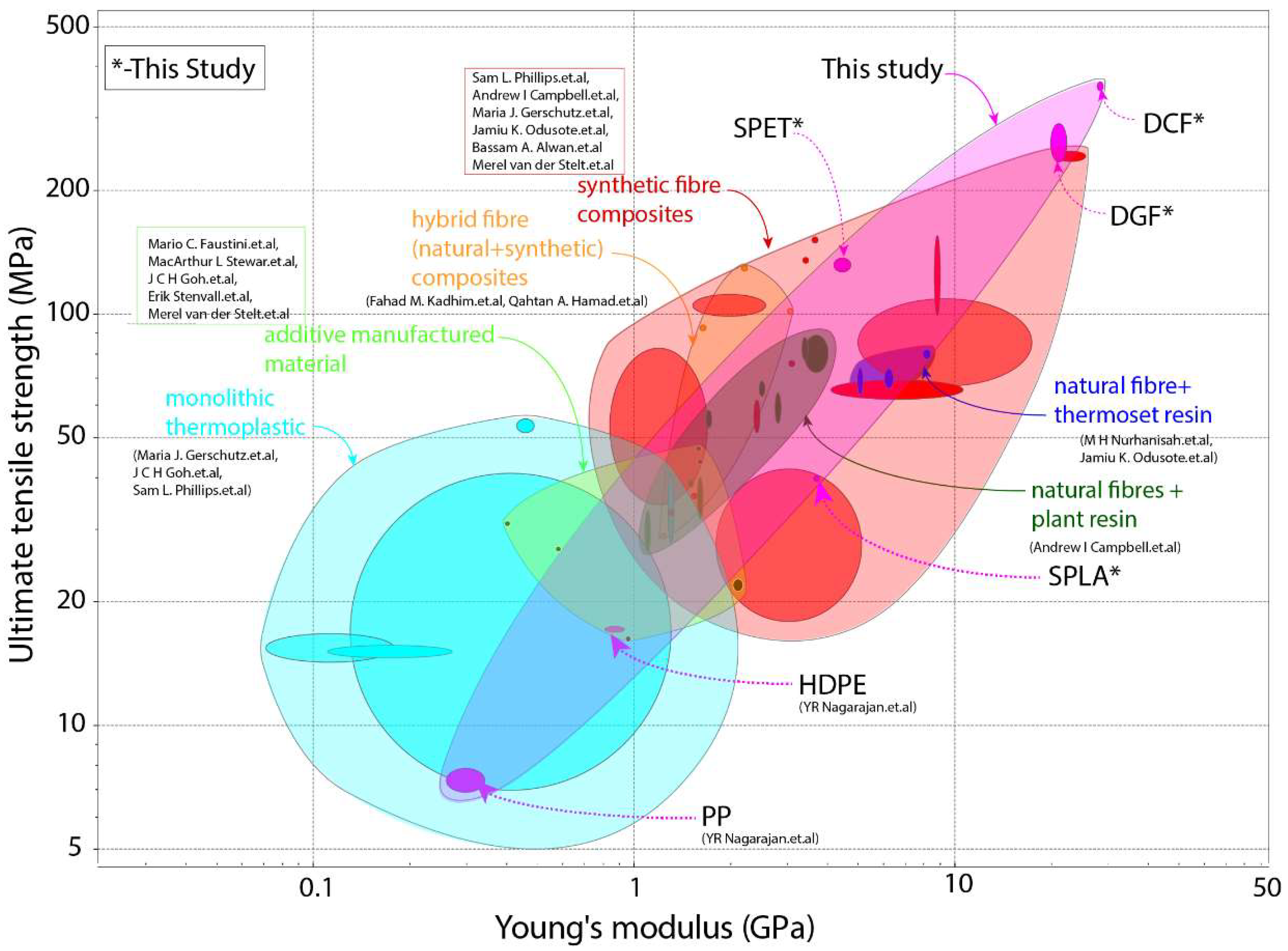
We commence our discussion by comparing the mechanical properties of the SPC and DPC composites with those of current prosthetic socket materials. We chose ultimate tensile strength and Young’s modulus as critical mechanical properties of the socket materials to meet the ISO strength requirement.
Figure 11 depicts these properties alongside those of unreinforced plastics and additively manufactured materials. Notably, the strength and stiffness of SPC and DPC can cover the entire range of commonly used prosthetic socket materials. However, it is important to note that various parameters such as composite layup, orientation, architecture (woven or knitted), and infill density govern the materials’ mechanical properties. Thus, a direct comparison is challenging due to the wide range of materials with different combinations and architectures. We scrutinized materials tested in socket form, with only eight open literature studies reporting both socket structural testing and relevant mechanical properties of the material used.
Material cost, socket weight, and socket strength were identified as critical performance indicators for comparing prosthetic sockets using the Technique for Order of Preference by Similarity to Ideal Solution (TOPSIS) [
47]. To rank the materials, we considered the cost of SPLA, SPET, DGF, and DCF woven fabric per kilogram, which are USD 25, USD 13, USD 10, and USD 32, respectively. However, the material cost of other materials in
Table 3 has not been reported. We used a linguistic scale from 1 (low cost) to 10 (expensive) for comparison. The decision criteria, represented by
, for material cost, socket weight, and strength are shown in
Table 3. We only considered sockets that met the strength requirement of ISO 10328 from A100 to A125, which can adequately support an amputee body mass of 100 kg to 175 kg.
First decision criteria,
is normalised by using the equation:
The resulting normalised decision matrix,
, for material cost, socket weight, and strength are presented in
Table 3. This normalised decision matrix is then further weighted based on the importance criteria,
, as presented in
Table 4. Material cost and weight are given equal importance, while socket strength has higher importance than their cost and weight.
Using the following equation, we apply the importance criteria weights to the normalised matrix.
The
is the normalised decision matrix used to calculate the performance metrics of the socket material and is presented in
Table 3. The normalised decision matrix
is then further used to determine the ideal best and worst value for each decision criteria of the socket by using the Equation:
The calculated ideal worst,
, and best,
, values are presented in
Table 4. These values are used to determine the Euclidean distance or separation distance,
and
, from ideal worst and best value by using the Equation:
The calculated separation distance,
and
, are reported in
Table 5. These values are used to calculate the performance index using the Equation:
Table 5 lists the calculated performance index,
, used to rank the prosthetic socket materials based on material cost, weight, and strength.
The rankings presented in
Table 5 enable us to compare various socket materials based on normalized weights. The performance index of SPC and DPC composites exceeds that of traditional high-performance prosthetic socket materials by over 50%, with the SPC and DPC sockets occupying the top four rankings in
Table 5. Considering that SPLA bio-degradable and SPET are fully recyclable and widely available, SPET emerges as the most suitable material for fabricating prosthetic sockets. It is worth noting that SPC is easy to manufacture with commingled yarns and does not require resin infusion.
Moreover, SPC offers the advantage of being easily remoulded using a hot-air gun, enabling prosthetic socket correction based on amputee feedback during fitting or after prolonged use. In contrast, advanced thermoset composite composites meet necessary socket strength requirements, but lack the flexibility for modification after consolidation, necessitating new socket fabrication for geometry adjustments based on user feedback. While high-performance toughened thermoplastics offer similar flexibility to SPCs, they remain inaccessible to low-resourced nations. Conversely, 3D-printed sockets demonstrate poor performance, with less than 25% efficiency, due to high costs and fabrication time.
Socket strength alone does not suffice as the sole criterion for measuring performance; it merely ensures safe body weight support. The assessment of a newly manufactured socket’s performance requires user feedback on fit and walking ability without support. Patient trials conducted in India have yielded positive feedback, with participants expressing high levels of satisfaction and continued usage of provided sockets. Long-term follow-up assessments revealed significant improvements in participants’ quality of life, underscoring the effectiveness of personalized and optimized socket designs in enhancing mobility and comfort for amputees. In summary, our discussion underscores the significance of personalized and optimized socket designs, highlighting SPC and DPC composites as promising materials for enhancing mobility and comfort for amputees. The integration of patient trials and feedback mechanisms is vital for advancing prosthetic socket technology and improving outcomes for amputees worldwide.
5. Conclusions
In conclusion, our study showcases the successful development of a cost-effective manufacturing approach for prosthetic sockets using single polymer composite (SPC) and dual polymer composite (DPC). Using purpose-built infrared curing ovens, commingled yarn, and reusable vacuum bags, we have demonstrated the feasibility of producing novel prosthetic sockets from SPC and DPC composites without requiring resin infusion.
Our findings indicate that SPLA sockets meet the A100 (100 kg) level strength requirement, while SPET, DGF, and DCF sockets surpass this standard, meeting the more stringent A125 (175 kg) level. This underscores the robust structural integrity of SPC and DPC prosthetic sockets, which can be further optimised by adjusting the wall thickness. Using the Technique for Order of Preference by Similarity to the Ideal Solution (TOPSIS) method, we conducted a comprehensive comparative assessment of prosthetic sockets based on material cost, socket weight, and strength. Our analysis reveals that SPLA sockets outperform SPET, DGF, and DCF sockets across these decision criteria, highlighting their cost-effectiveness and strength performance.
Furthermore, our study identifies the SPET socket as an ideal candidate for prosthetic socket applications due to its mouldable nature and recyclable properties. Additionally, DGF and DCF sockets demonstrate significant potential for fabricating sockets tailored to the needs of active amputees, offering versatility and durability. The performance index of all tested sockets surpasses that of commercially available prosthetic sockets, indicating the superior performance and potential of SPC and DPC composites in prosthetic manufacturing. These materials offer enhanced strength, adaptability, and cost-efficiency compared to traditional alternatives.
To summarize, our research contributes to advancing prosthetic socket technology by providing a cost-effective, customizable, and high-performance solution. SPC and DPC composites hold great promise for improving mobility, comfort, and overall quality of life for individuals with limb loss. Further studies and clinical trials are warranted to validate and refine the efficacy of these innovative prosthetic socket materials in real-world applications.
