1. Introduction
Implants have revolutionized the field of dentistry by providing a reliable and long-term solution for replacing missing teeth. Advancements in implant technology, materials, and techniques have significantly enhanced their success rates [
1,
2]. Improvements in implant materials, such as the development of titanium alloys, have made implants more durable and biocompatible, reducing the risk of rejection or failure [
3]. Additionally, advancements in imaging technology, like 3D imaging and computer-guided implant placement, allow for the more precise planning and placement of implants, which contributes to their success [
4]. The cervical area, where the crown meets the root of a natural tooth, plays a significant role in the appearance and function of the tooth. Mimicking this area in dental implants involves creating a seamless transition from the implant fixture to the prosthetic crown. This not only contributes to a more natural appearance but also helps in maintaining healthy gum tissue and proper function during biting and chewing. Creating implants that closely resemble natural teeth, especially in the critical cervical area, contributes not only to the patient’s satisfaction but also to the long-term success and stability of the implant restoration.
The maxilla (upper jaw) and mandible (lower jaw) exhibit distinct physical characteristics in terms of their structure and density, which have implications for implant placement and treatment outcomes. The classification of bone quality, as outlined by Lekholm and Zarb, categorizes bone density into four types: D1, D2, D3, and D4. This classification system helps in understanding the bone characteristics at potential implant sites [
5]. The mandible is said to have D2 bone quality and the maxilla has D4 bone quality. The mandible has a higher proportion of cortical bone (dense outer layer) compared to the maxilla, which contains more cancellous or trabecular bone (spongy inner bone). The cortical bone offers better primary stability for implants, thus requiring less bone grafting or additional procedures to support the implant in the mandible. The maxilla’s cancellous bone might necessitate additional care during implant placement to ensure stability [
6]. The difference in bone quality between the maxilla and the mandible, with the mandible typically having denser bone quality, influences the treatment approach and considerations during implant placement.
The decision to select the prosthetic framework involves considering various factors to ensure the long-term success, stability, functionality, and aesthetics of the restoration [
7,
8]. Metal–ceramic combinations have traditionally been used due to their strength, durability, and satisfactory aesthetics. However, with advancements in material science, zirconia, a type of ceramic, has gained popularity for its improved strength and aesthetics [
9,
10]. Zirconia restorations offer high biocompatibility and excellent mechanical properties, making them suitable for certain implant-supported prostheses [
11,
12].
Zirconium oxide, commonly referred to as zirconia, has gained significant popularity in dentistry due to its excellent properties and versatility in various dental applications [
13]. Zirconia is currently used as a core material for the fabrication of prosthetic frameworks for teeth and implant-supported fixed partial dentures. In addition, zirconia is considered more biocompatible than other ceramics, titanium, and metal alloys, which may facilitate soft tissue responses in terms of health [
14]. With increasing public demand for aesthetically pleasing restorations, there has been an increase in the application of all ceramic restorations, with yttria-stabilized tetragonal zirconia polycrystal being one of them since it has higher flexural strength (800–1500 MPa) and fracture resistance [
15]. Since zirconia ceramics are opaque, to make them more aesthetically pleasing, it is covered by a layer of glass ceramic. The zirconia full-coverage crown without veneering dental porcelain has the advantage that no dental porcelain is fractured due to the absence of an upper structure, and hence it is preferred in areas of high masticatory load. Since clinical studies have shortcomings, finite element analysis (FEA) is a numerical stress analysis technique that has proven to be a useful tool in investigating the effect of the biomechanical properties of prostheses on dental implants [
16]. Several in vitro studies and FEA were conducted to explore stress transmission at both the implant and peri-implant levels, employing various restorative materials for implant-supported prostheses [
17,
18,
19,
20,
21]. This study was conducted to evaluate and compare the effect of monolithic zirconia and In-Ceram zirconia superstructures on the distribution of stresses in implants and D2 and D4 bone densities after the application of a vertical and oblique occlusal load of 200 N with the aid of a three-dimensional finite element study. Stress levels were calculated using maximum and minimum von Mises stress values.
3. Results
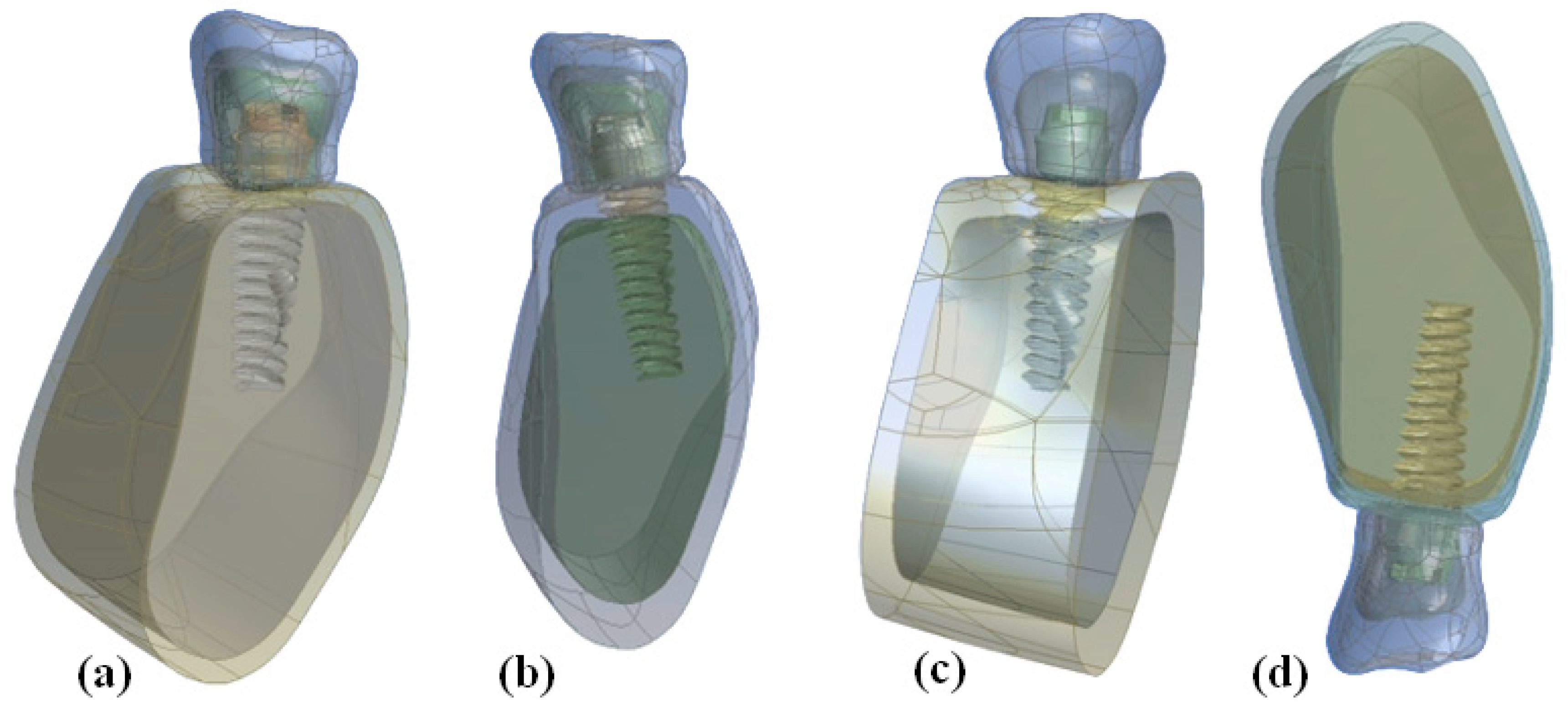
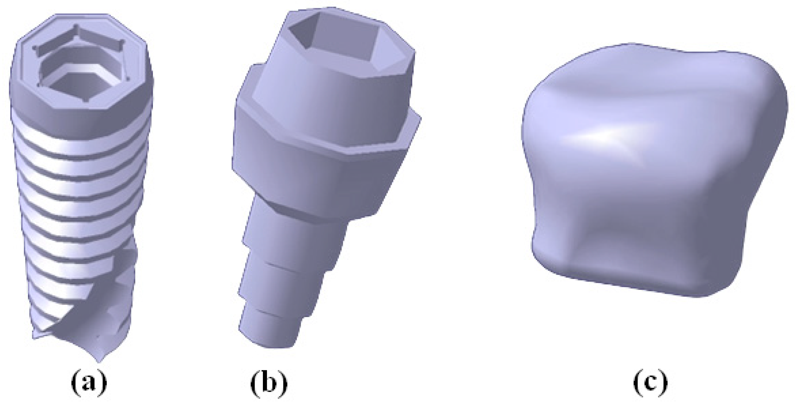
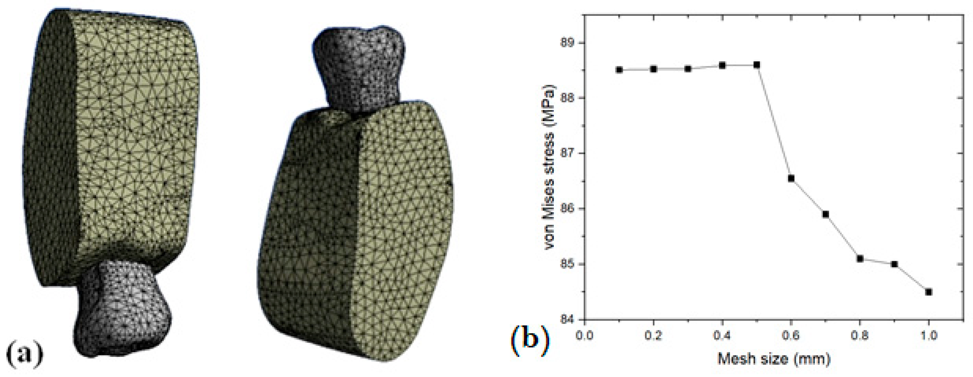
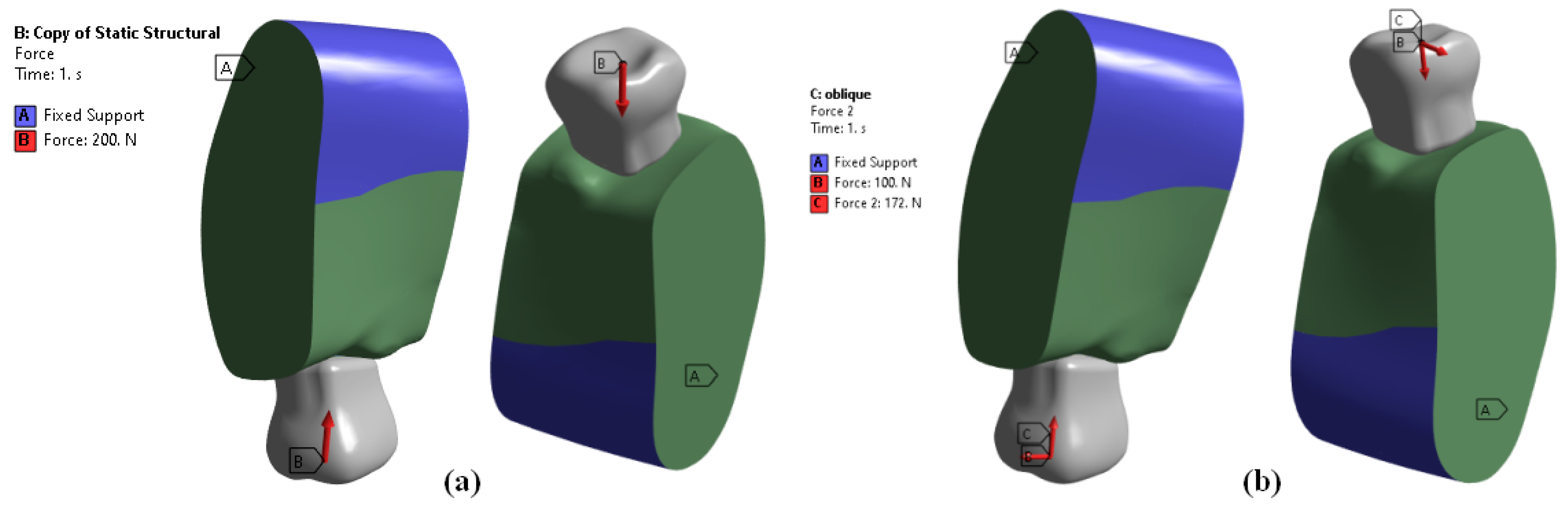
Four 3D finite element models were built with 3D modelling software (CATIA-3D EXPERIENCE R2019x) to analyze the stress distribution in two different bone densities with three different all-ceramic superstructures. Out of the four models, two models were used to calculate stress distribution in D2 bone and the other two models were used to calculate stress distribution in D4 bone. For each bone density, the two models were MZ (monolithic zirconia) and ZP (zirconia framework with porcelain veneering). Each set of models contained a crown, a cement layer, an abutment, an implant, and surrounding bone, which received a 200 N occlusal load. Stress distribution in the implant and surrounding bone was analyzed using 3D Finite Element Software (ANSYS WORKBENCH 2023 R2). For each model, stress levels were calculated using maximum and minimum von Mises stress values.
In the present study, different all-ceramic materials, namely In-Ceram zirconia and monolithic zirconia, used in a single implant-supported prosthesis in two different bone densities under static functional forces, affected the stress concentration.
3.1. Stress Distribution within the Implant
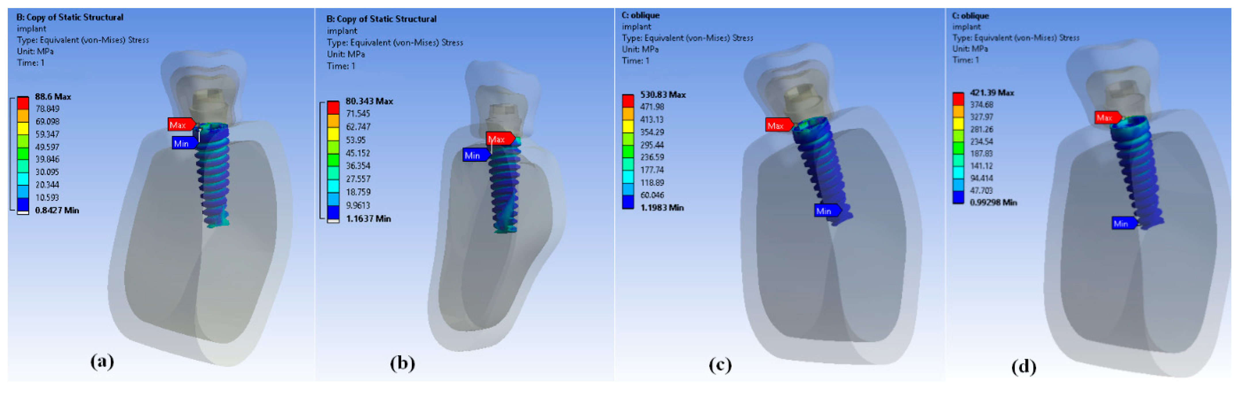
Regardless of bone density or loading forces (vertical or oblique), the maximum von Mises stresses were concentrated at the neck of the implant [
Figure 5a,b]. This area tends to experience higher stress due to the mechanical forces transmitted during chewing or biting. Under vertical loading forces, the minimum stresses were concentrated at the first thread from the neck of the implant in all models. This area experiences lower stresses compared to other parts of the implant structure when subjected to vertical forces. Interestingly, for oblique loading forces, the minimum stresses were concentrated at the root apex (bottom) of the implant in all models [
Figure 5c,d]. This indicates that under oblique loading, the stress distribution differs, with lower stresses observed at the root apex compared to other areas.
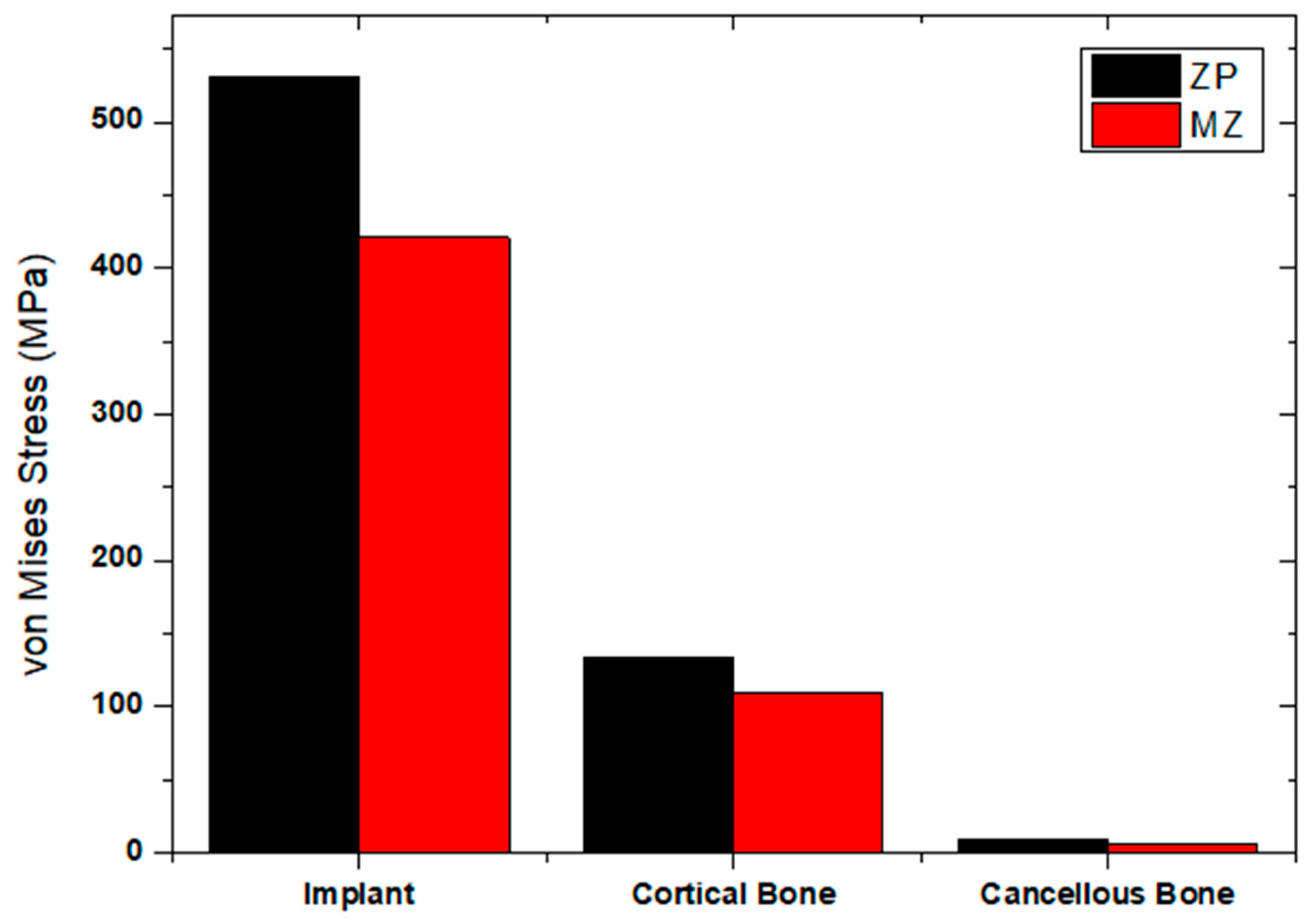
The maximum von Mises stresses within the implant were 88.6 MPa for the ZP model and 80.34 MPa for the MZ model. These values represent the highest stresses experienced within the implant structure when subjected to vertical loading forces. Under oblique loading conditions, the maximum von Mises stresses within the implant were reported as 530.83 MPa for the ZP model and 421.39 MPa for the MZ model:
Figure 5c,d. These stress values provide crucial information about the mechanical behavior and potential failure points within the implants under different loading scenarios, especially considering the bone density when classified as D2.
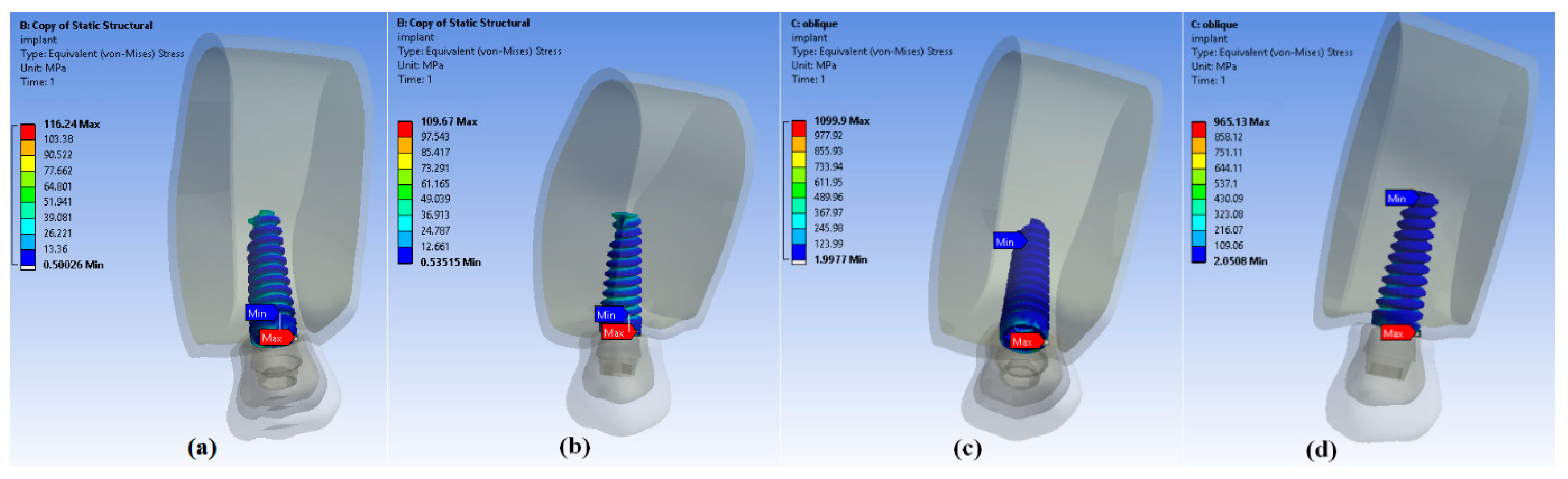
In scenarios involving D4 bone density, as shown in
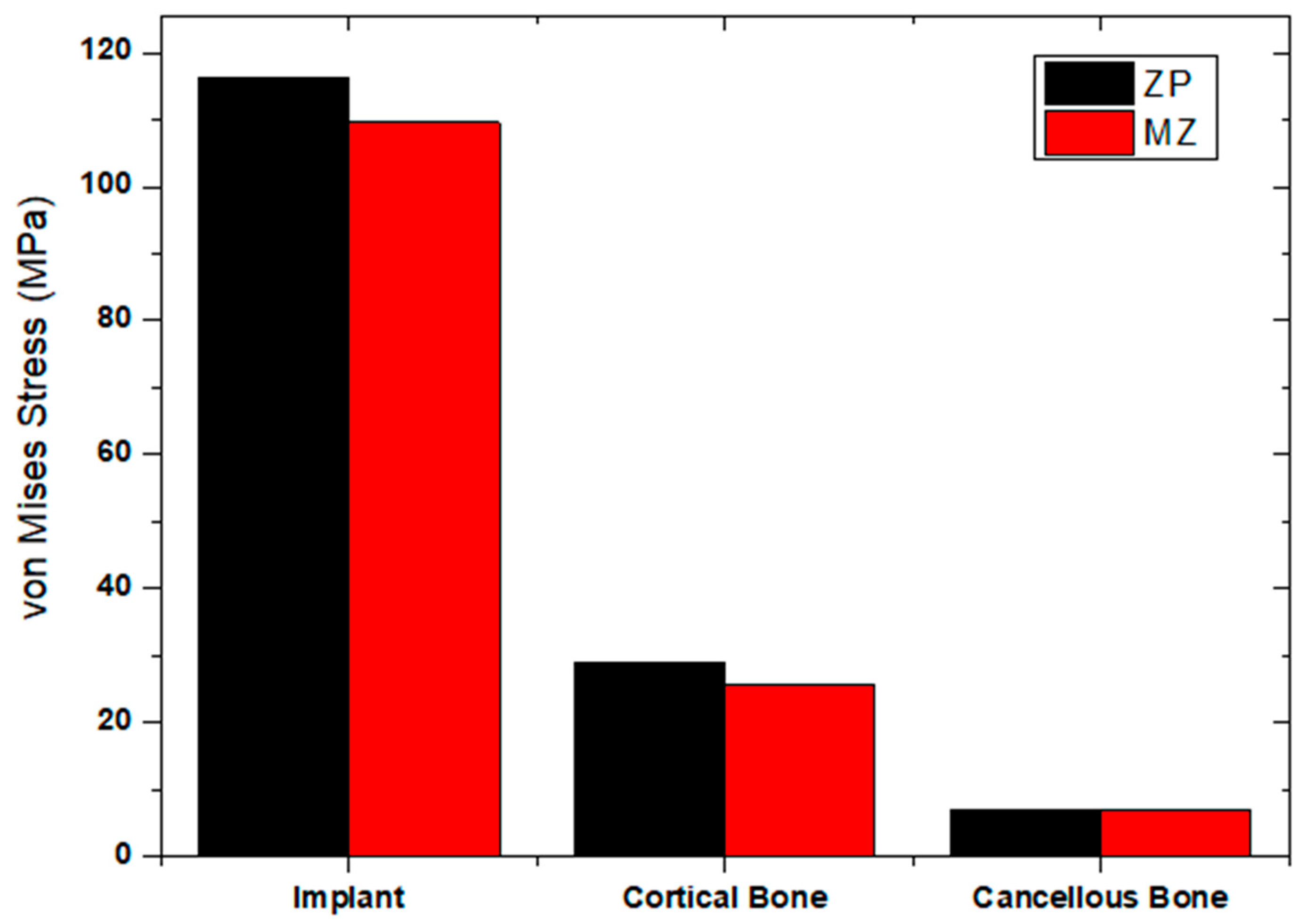
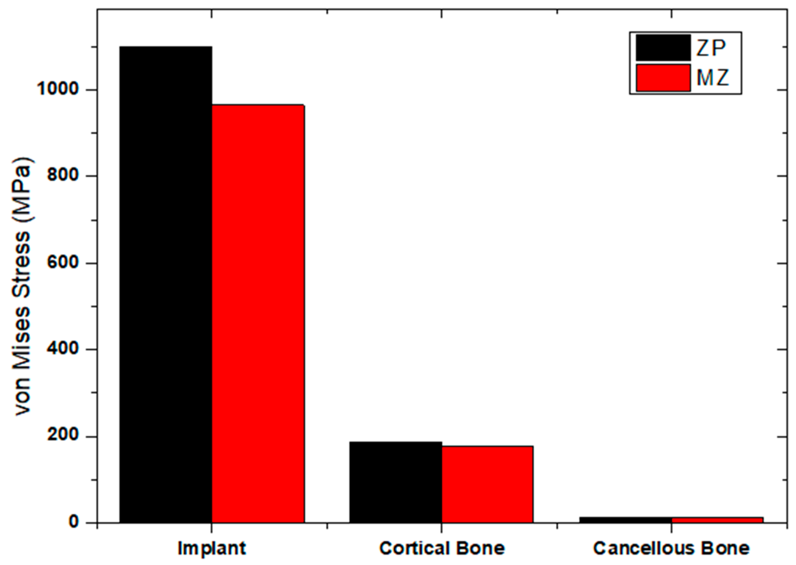
Figure 6a,b, the maximum stresses within the implant under vertical loading were reported as 116.24 MPa for the ZP model and 109.6 MPa for the MZ model. Under oblique loading conditions with D4 bone density, the maximum stresses within the implant were reported as 1099 MPa for the ZP model and 965.13 MPa for the MZ model, as shown in
Figure 6c,d. The notably higher stress values under oblique loading compared to vertical loading in the context of D4 bone density highlight the increased susceptibility of implants to higher stresses when subjected to forces at an angle.
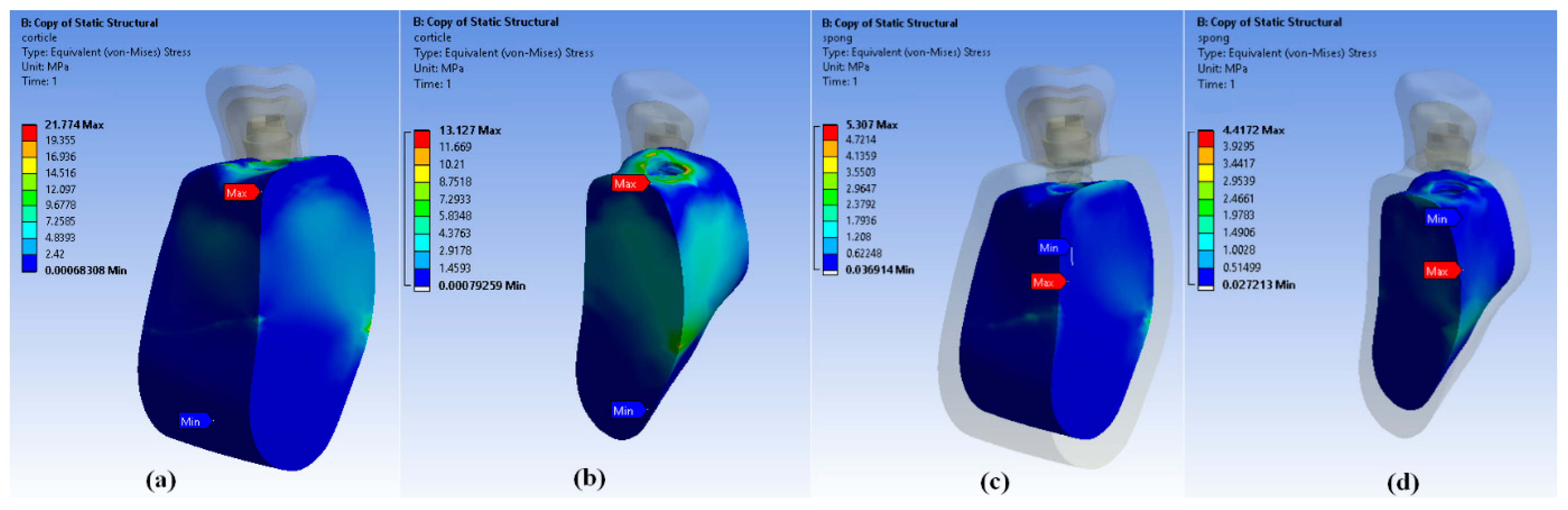
3.2. Stress Distribution within the Supporting Bone of D2
Under vertical loading, the maximum stresses were observed in the cervical cortical bone region for all models (ZP and MZ). This area experienced the highest stress concentration when subjected to vertical forces. The maximum von Mises stresses observed in the cortical bone region were 21.77 MPa for the ZP model and 13.12 MPa for the MZ model [
Figure 7a,b]. This indicates higher stresses in the cortical bone for the ZP model compared to the MZ model under vertical loading conditions. The maximum stresses observed in the cancellous bone under vertical loading were 5.30 MPa for the ZP model and 4.41 MPa for the MZ model [
Figure 7a,b]. Here, the ZP model also exhibited slightly higher stresses in cancellous bone compared to the MZ model under vertical loading conditions. Generally, higher stresses were seen in both models (ZP and MZ) under vertical loading compared to oblique loading forces in both cortical and cancellous bone regions. This indicates that the cervical cortical bone region experienced higher stress concentrations under vertical loading conditions compared to oblique loading conditions.
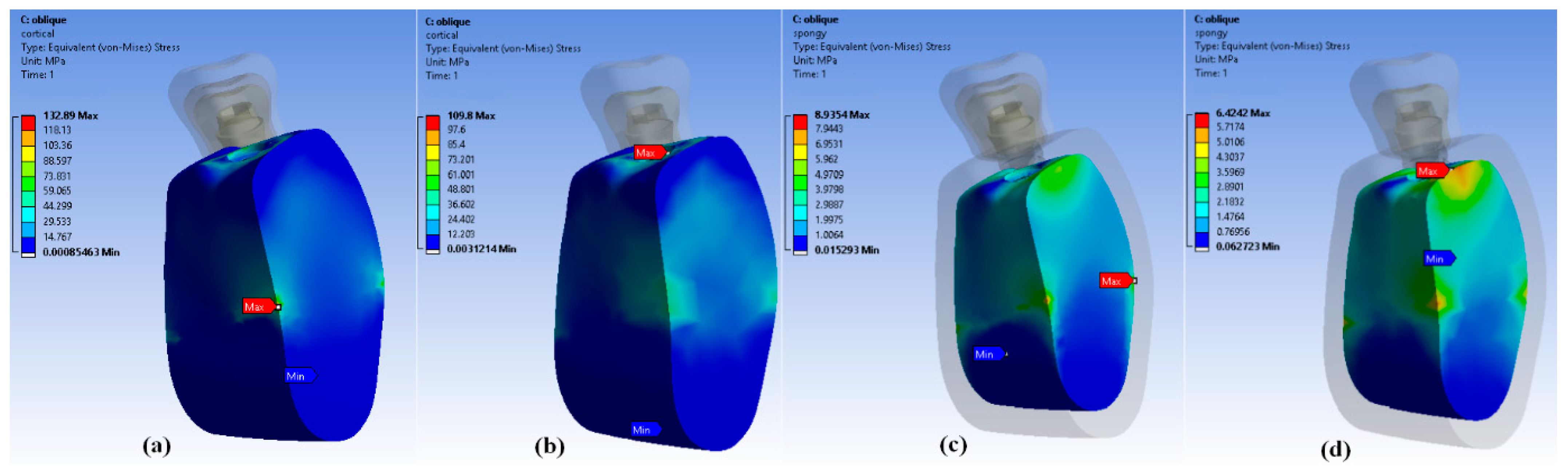
The maximum von Mises stresses were observed in both cortical and cancellous bone regions under oblique loading conditions for the ZP and MZ models. For the ZP model, the maximum von Mises stress observed in the cortical bone under oblique loading was 132.8 MPa. For the MZ model, the maximum stress observed in the cortical bone under oblique loading was 109.8 Mpa [
Figure 8a,b]. This indicates higher stress concentrations in the cortical bone for the ZP model compared to the MZ model when subjected to oblique loading forces.
In the cancellous bone under oblique loading forces, the maximum stresses were 8.93 MPa for the ZP model and 6.42 MPa for the MZ model [
Figure 8c,d]. Similar to the cortical bone, the ZP model exhibited higher stresses in cancellous bone compared to the MZ model under oblique loading conditions. These findings suggest that both cortical and cancellous bone regions experienced higher stress concentrations under oblique loading forces, and the ZP model showed higher stress values compared to the MZ model in both types of bone tissues.
3.3. Stress Distribution within Supporting Bone of D4
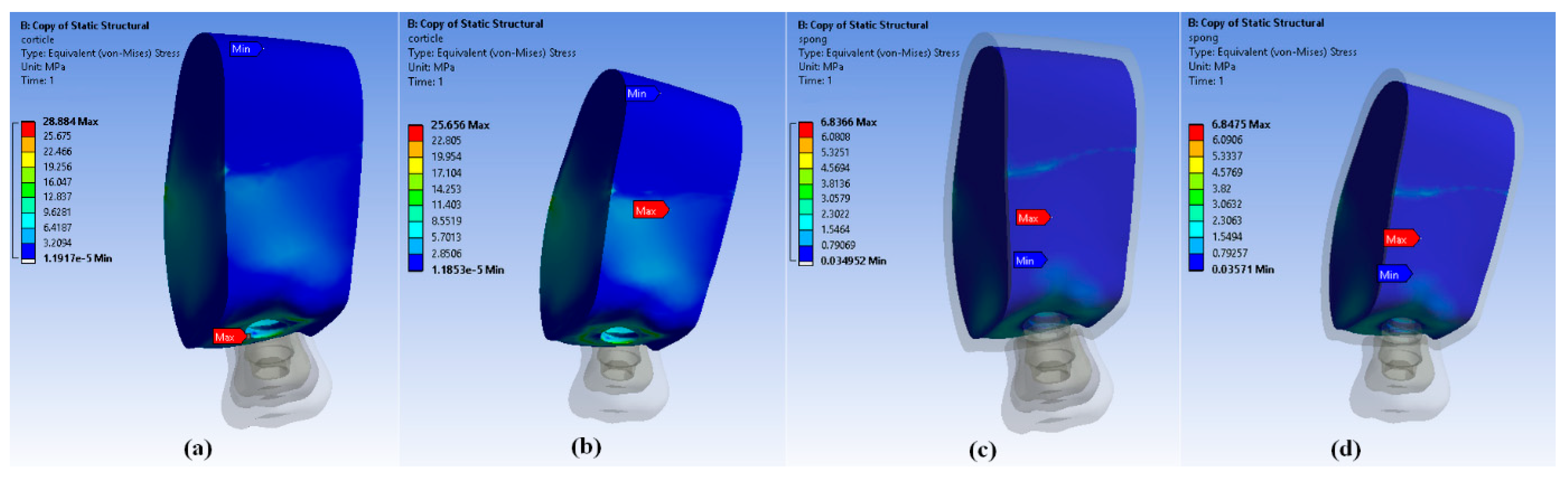
Under vertical loading forces, the maximum von Mises stresses were observed in the cervical cortical bone region for all models (ZP and MZ). This area experienced the highest stress concentrations when subjected to vertical forces. The maximum von Mises stresses observed in the cortical bone region were 28.88 MPa for the ZP model and 25.65 MPa for the MZ model [
Figure 9a,b]. This indicates higher stresses in the cortical bone for the ZP model compared to the MZ model under vertical loading conditions. Interestingly, for cancellous bone, all the models showed the same stress values for both vertical and oblique loading forces, with maximum stresses of 6.83 MPa [
Figure 9c,d]. This suggests consistent stress levels in cancellous bone regardless of loading direction or model type. These findings provide valuable insights into the stress distribution within different bone regions (cortical and cancellous) under varying loading conditions and for different implant models. The information can be used for optimizing implant designs and selecting suitable implants to minimize stress concentrations and ensure long-term stability, especially considering the cervical cortical bone region’s vulnerability to higher stresses under vertical loading forces.
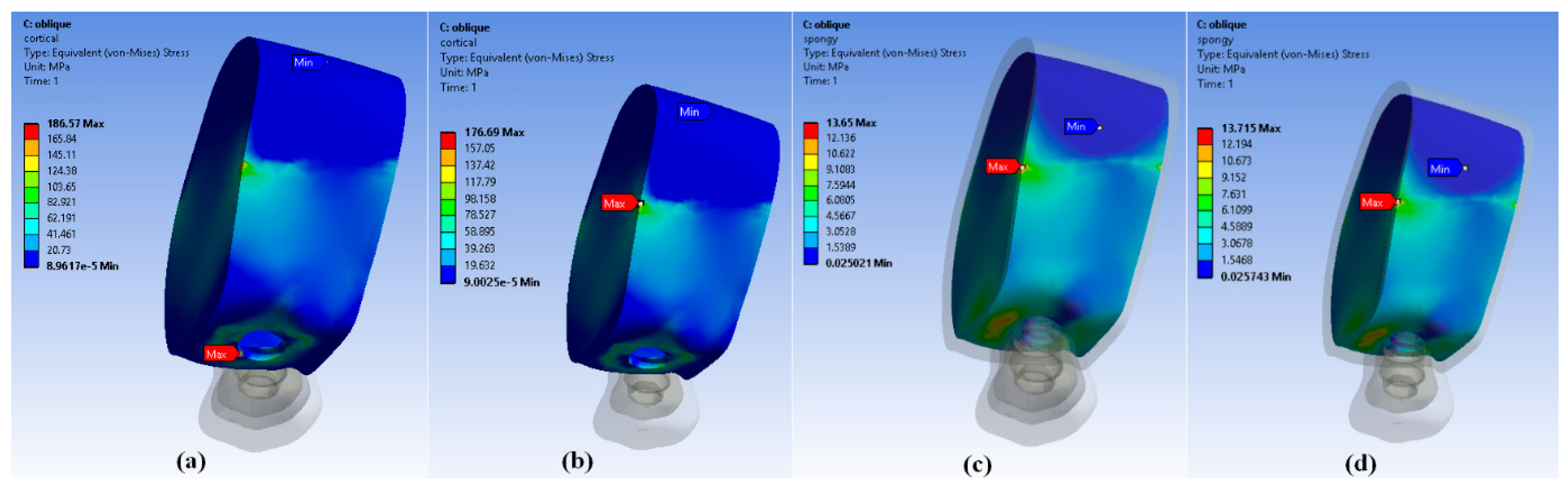
Figure 10 shows the maximum von Mises stresses within the cortical and cancellous bone regions under oblique loading conditions for different models (ZP and MZ). For the ZP model, the maximum von Mises stress observed in the cortical bone under oblique loading was 186 MPa. For the MZ model, the maximum stress observed in the cortical bone under oblique loading was 176.6 MPa [
Figure 10a,b]. This indicates higher stress concentrations in the cortical bone for the ZP model compared to the MZ model when subjected to oblique loading forces. Similar to previous observations, the stress values in cancellous bone remained consistent across all models for both vertical and oblique loading forces. The maximum stress in the cancellous bone under vertical loading was 6.83 MPa for all models. Under oblique loading conditions, the maximum stress in cancellous bone was recorded as 13.6 MPa for all models [
Figure 10c,d]. This consistency across models suggests that the stress levels in cancellous bone were uniform regardless of loading direction or model type.
The results of stresses in the D2 and D4 bone are summarized in
Table 4,
Table 5,
Table 6 and
Table 7 with respect to loading conditions on implant, cortical bone, and cancellous bone.
4. Discussions
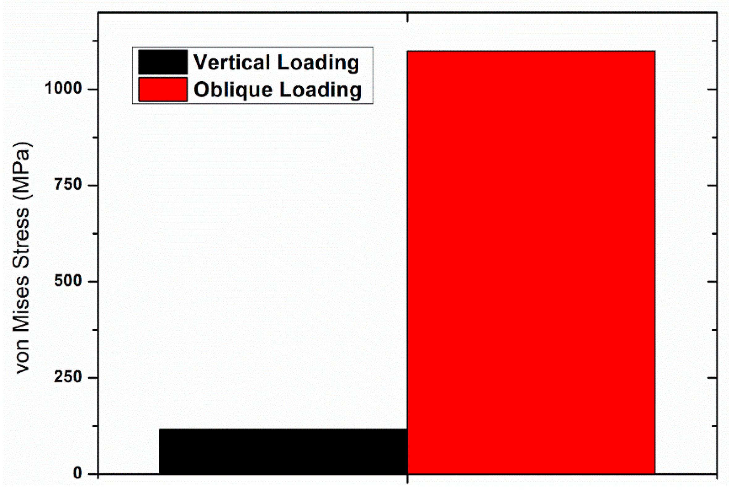
The current study utilizes finite element analysis to evaluate and compare the effect of In-Ceram zirconia (ZP) and monolithic zirconia prosthetic (MZ) materials on the distribution of stresses in implants and surrounding bone in maxillary and mandibular sections of bone. In a study conducted by Papavasiliou et al. [
31], they found that oblique loads could increase stress by as much as 10-fold. Similar results were obtained with the present study, as shown in
Figure 11, where the stresses with oblique loading were higher than vertical loading irrespective of the bone type and the prosthetic superstructure [
32].
The current study utilizes finite element analysis to evaluate and compare the effect of In-Ceram zirconia (ZP) and monolithic zirconia prosthetic (ZP) materials on the distribution of stresses in implants and surrounding bone in maxillary and mandibular sections of bone.
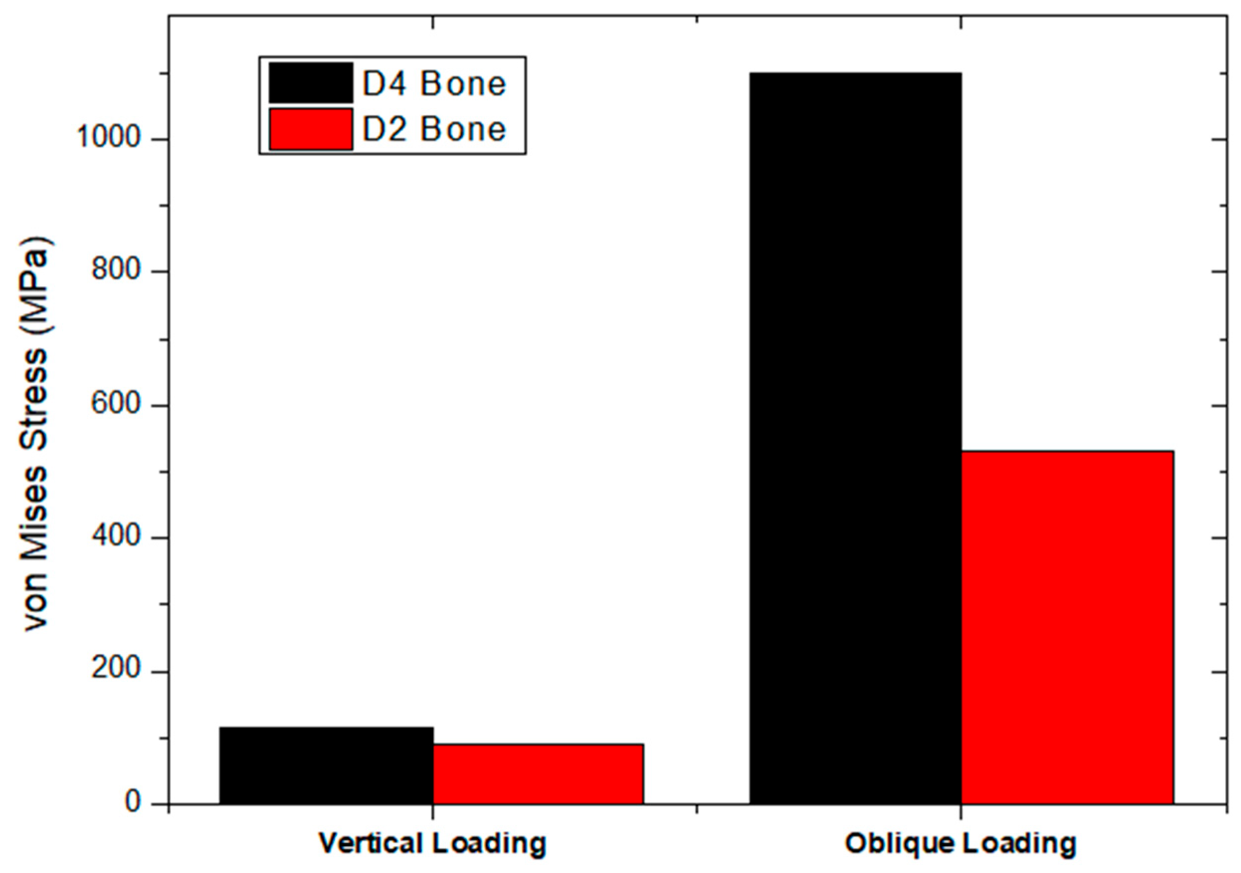
Primary stability, which is one of the deciding factors for implant success, is dependent on bone quality. Higher implant success rates are seen in denser bone than porous bone, as cortical bone is more resistant to deformation due to a higher modulus of elasticity [
33,
34]. Based on the Hounsfield unit, Misch [
35] classified bone density into four types—D1, D2, D3 and D4 [
36]. It is proven that more stresses are generated in D3 and D4 bone compared to D1 and D2 bone [
26,
37]. In the present study, also, higher stress was seen in the D4 bone than in the D2 bone [
Figure 12].
Osseointegration failure begins around the implant neck as more stresses are concentrated in the crestal region than the apical region [
31,
38]. Similar results were seen in the present study.
Even though there is a shift towards aesthetic restorations, all ceramics have a limited area of use as they are brittle. Hence, monolithic zirconia was introduced as it lacks porcelain veneering and therefore can be used even in case of parafunctional habits [
39]. In the current study, different occlusal surface materials and frameworks generated different stresses in implants and the surrounding bone. The ZP model experienced higher maximum von Mises stresses in the cortical bone compared to the MZ model. This suggests that the ZP model exhibited greater stress concentrations within the cortical bone structure when subjected to vertical loading forces in the context of D4 bone density [
Figure 13].
The present study showed the least amount of von Mises stresses in the cancellous bone of D2 quality in the MZ model on vertical loading (4.417 MPa) (
Figure 14. Maximum stresses were generated in the implant compared to the cortical bone because the Young’s modulus of the implant (110 GPa) was higher than that of the bone (13.7 GPa). When the magnitude of stresses was compared in implants, among the ZP and MZ models, it was found that maximum von Mises stresses are concentrated in the ZP model in the D4 bone on oblique loading (1099 MPa) (
Figure 15). This is because of the presence of porcelain veneer. Similar results were seen by Sevimay et al. [
26]. Hence, it is concluded that physical and mechanical properties must also be considered, apart from aesthetics, for the long-term success of implants. The discrepancy in stress values between the ZP and MZ models suggests that the structural features or design of the ZP model may result in elevated stress concentrations within the cortical bone when exposed to oblique loading in D2 bone density scenarios [
Figure 16].
Limitations
The work presented has several strengths, such as its comprehensive evaluation of stress distribution in dental implants using finite element analysis. However, there are notable limitations that should be considered. Firstly, the study relies heavily on numerical simulations (finite element analysis) rather than empirical data from clinical trials. While finite element analysis provides valuable insights, the actual clinical outcomes might differ due to various factors, including biological variations and patient-specific conditions. Additionally, the study assumes homogeneity and linear elastic behavior for all materials, neglecting potential nonlinear and time-dependent characteristics. The material properties used in the analysis are derived from literature sources, introducing the possibility of variability and a lack of consideration for individual patient differences.
Furthermore, the study does not account for dynamic loading conditions that teeth and implants experience during functional activities. Chewing and biting forces are dynamic and multifactorial, and the static load of 200 N applied in this study may not fully represent real-world conditions.
In conclusion, while the finite element analysis provides valuable theoretical insights, the limitations, including the lack of clinical validation, simplified material properties, and static loading conditions, should be acknowledged. Future studies should aim to bridge the gap between numerical simulations and clinical reality by incorporating more realistic parameters and empirical data.


 ,
, 


