Technical Note

Controlling a Below-the-Elbow Prosthetic Arm Using the Infinity Foot Controller

Department of Mechanical Engineering, California State University, Northridge, CA 91330, USA
*
Author to whom correspondence should be addressed.
Prosthesis 2023, 5(4), 1206-1231; https://doi.org/10.3390/prosthesis5040084
Submission received: 18 August 2023 / Revised: 3 November 2023 / Accepted: 13 November 2023 / Published: 20 November 2023
(This article belongs to the Special Issue Innovations in the Control and Assessment of Prosthetic Arms)

Abstract

:
Nowadays there are various prosthetic arm designs in the literature, the market, and CAD design websites, with different shapes, sizes, and degrees of freedom. Only limited options are available for controlling such prostheses. Prosthetic arm users reported muscle fatigue and unreliability when using the market-dominated myoelectric sensors. This work presents the “Infinity Foot Controller” as a new approach to control a five-finger below-the-elbow prosthetic arm with wrist rotation and bending capabilities. This foot control system receives user input from a custom insole and a sensor-controller unit placed alongside the user’s shoe to perform various hand grips, gestures, and/or rotations. To demonstrate the new foot controller, a design of a 3D-printed below-the-elbow prosthetic arm, called the “Infinity Arm”, is presented. This arm is suitable for gripping relatively lightweight objects and making hand gestures. It includes a wrist actuation system that permits 120° wrist rotation and 70° wrist extension and flexion. It also includes a haptic feedback system that utilizes fingertip force sensors to relay a vibratory response in an armband placed on the user’s arm, giving the user a sense of touch. A proof-of-concept model was built to demonstrate the system and a testing procedure was proposed.

Graphical Abstract

1. Introduction

Controlling prosthetic arms in an easy, effective, and noninvasive way is one of the most challenging tasks. Surface electromyography (sEMG) is the most used approach for prostheses control. Geethanjali [1] presented a state-of-the-art review of myoelectric control of prosthetic hands [2]. sEMG requires some capable muscles to exist in the residual limb to strain the myoelectric sensors. Prosthetic users reported muscle fatigue and unreliability when using myoelectric sensors. Some pattern recognition approaches were proposed to reduce direct control by prosthetic users. However, the main issue of sEMG pattern recognition-based systems is that they rely on the repeatable matching of the produced sEMG patterns during prosthesis manipulation to those used for system training. These patterns tend to significantly change due to environmental factors such as sweat or electrode shift, as well as fatigue, load, limb position, or simply due to the user’s change of focus [3,4,5]. Another drawback of these solutions is their limited ability to successfully cope with simultaneous motions, which makes them still not fully intuitive and somewhat cognitively demanding [6].
Searching for novel and innovative approaches to control upper limb prostheses, alternative control methods have been proposed recently, such as electroencephalography (EEG), or brain wave control [7,8,9], and voice control [2,9,10]. In general, EEG needs considerable mental concentration to give reliable results and is affected by distractions and the amount of hair in the scalp. Voice control is very reliable but requires the users to talk to their prostheses, which might not be always desirable. In 2020, Hazubski et al. [11] presented a proof-of-concept study on a new approach to control a prosthesis, an exoskeleton, or an end effector visually using augmented reality glasses. In 2022, Nagaraja et al. [12] proposed a breathing-powered system for body-powered prostheses. Sonomyography (SMG) [13,14,15,16], or ultrasound-based sensing/imaging, has also been used to control prostheses.
Using the foot to control prosthetic arm motions has been proposed by multiple research groups, but most designs relied on identifying foot postures using sEMG. Most of these designs are intended to supplement arm sEMG, since the residual limb might lack enough muscle to control all degrees of freedom in the prosthesis. For example, Lyons and Joshi [17,18] used sEMG sensors placed on the lower leg and mapped the degrees of freedom of the leg to those of the arm, to enable noninvasive control of prosthetic elbow, wrist, and hand movements with minimal training. This was based on a case study that showed intuitive mapping between the human hand and foot movements [19]. Maragliulo et al. [20] used sEMG foot band as a hands-free wearable human machine interface (HMI) that can classify five foot gestures. They also added a locking/unlocking mechanism controlled by one of the gestures to eliminate undesired gesture classification during general leg movements (walking, jumping, climbing the stairs, etc.). Lee et al. [21] used a wearable fabric sensor on the lower leg to map foot postures to prosthetic hand postures. Their approach relied on convolutional neural networks (CNN) to classify eight leg postures based on pattern recognition. DEKA arm [22,23] included a foot controller that has force sensitive resistors (FSRs) soldered onto foot pads worn inside the shoes, in addition to inertial measurement units (IMU) mounted on a clip that attaches to the top of the shoe. The IMU utilizes gyroscopes and micro-electromechanical systems (MEMS) accelerometers to sense small movements of the foot/ankle.
This paper presents the design of the “Infinity Foot Controller” system to control a trans-radial (below-the-elbow) prosthetic arm. This system includes an insole controller to be placed inside a shoe or a sock and a sensor-controller unit (SCU) to be clipped to the side of the shoe or the sock to control prosthetic arm rotation and bending. Commands from two push buttons integrated in the insole underneath the toes, and from the gyroscope and accelerometers in the SCU, are transmitted wirelessly to the prosthetic arm to apply different grips and rotate or bend the prosthetic hand. The push buttons also provide audible feedback and haptic feedback to the user’s toes. In order to test and demonstrate the foot controller, a trans-radial 3D-printed arm, called the “Infinity Arm”, was designed with a capability to grip lightweight everyday objects, as well as bend and rotate the wrist. A haptic feedback system was also proposed to send vibratory motion to an armband placed on the residual limb in response to any pressure applied to fingertip force sensors from gripping or touching objects. Preliminary tests demonstrated the ability of humans to utilize the controller effectively after minimal training. The rest of the paper is organized as follows: The detailed designs of the foot controller, the arm, and the haptic feedback system are presented in Section 2. Manufacturing and testing performed to demonstrate the effectiveness of the new design and understand how training can improve the mastery of using the system are described in Section 3. A training approach is also proposed in this section. This is followed by Section 4 that declares the limitations of the system and lists the differences between Infinity and DEKA foot controllers. The paper is concluded with a Summary and Conclusions section.

2. Materials and Methods

2.1. Infinity Foot Controller Design

The Infinity foot control system is shown in Figure 1. It is composed of an insole controller and a sensor-controller unit (SCU). The insole controller is a sandwich structure of three layers. The bottom layer is 3D-printed from thermoplastic polyurethane (TPU) and has two controlling push buttons located underneath the toes, and wiring channels that allow for proper wire management. The middle layer includes PLA paddles placed above the push buttons to increase the surface area on which the user applies a force with their toes. The top layer is fabric for added comfort. A silicon molding adhesive in the middle layer is used to bond the top and bottom layers together once all components and wires are assembled properly. The silicon molding adhesive also serves as a shock absorber and an insulator for all electronic components. The shape of all layers is modeled after traditional insoles, sized 5–13.
The SCU housing is 3D-printed from polylactic acid (PLA) plastic and is clipped to the side of the shoe via a universal clip that allows secure mounting. The SCU includes housings for a Seeeduino XIAO BLE Sense microcontroller with an internal IMU, an RF transmitter, a rechargeable 400 mAh LiPo battery, a charging module, and a power slide switch. The charging module indicates the charge level with an LED and ensures that the Li-Po battery would not be overcharged. The microcontroller receives signals from the push buttons and the IMU’s sensors, and transmits these signals to the prosthetic arm to grip with the fingers, or to bend or rotate the wrist. The IMU’s gyroscope measures the foot rotation around the yaw-axis (dorsiflexion and plantarflexion) and around the pitch-axis (inversion and eversion) to, respectively, control bending (wrist extension and flexion) and rotation (supination and pronation) of the prosthetic arm’s wrist. The rotation around the roll-axis (internal and external rotations) may also be used to control either wrist deviation (abduction and adduction) or elbow rotation, if these degrees of freedom are added to a future version of the arm.
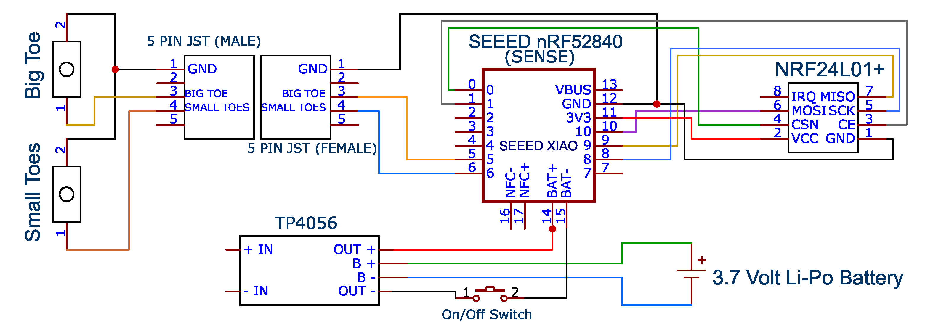
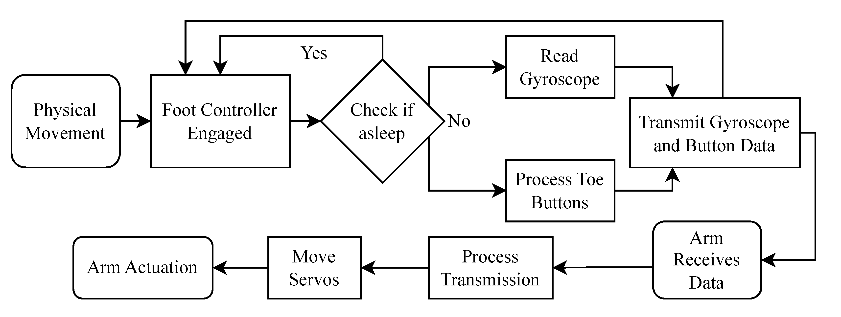
Data transfer between the foot control and the arm follows a custom protocol that relies on a “payload” made of three integers in a 1 × 3 array: [Type Index Direction]. The “Type” integer is either 0 for buttons, or 1 for a gyroscope axis shift. The “Index” integer is 0 for the big toe button press, 1 for the smaller toes button press, 2 for rotation (pitch gyroscope axis shift), or 3 for bending (yaw gyroscope axis shift). Finally, the “Direction” integer is used only for rotation and bending, and takes a value of +1 or −1 to indicate the direction of rotation or bending, or a value of 0 if the old position is the same as the new position. An example of this payload would be [0 1 1], where the first value (0) indicates a button pressed, and the second value (1) represents the small toes button. The last value is ignored in this case of a button press. Another example is [1 2 −1] which indicates an axis shift trigger (1), and this triggered axis is the pitch axis (2), and the rotation direction is negative (−1), which is to the right in this case. The system architecture diagram for the foot controller is in Figure 2. Once any physical movement happens in the foot, the IMU will be triggered, and the code checks if the Sleep condition is met. If the SCU is not in the Sleep mode, the pitch and yaw offsets will be calculated after setting a new center position for the axes. Also, the two buttons will be checked for a trigger. The measured data (buttons pressed or axes shifted) are then processed to assign “Type”, “Index”, and “Direction” for the payload array to be transmitted wirelessly. The wiring diagram is shown in Appendix A (Figure A1). The overall architecture of the foot controller with the arm is in Figure 3. Physical movement of the foot are captured if the foot controller is engaged and is not in the Sleep mode. The data of gyroscope axes shifts and button presses are collected and transmitted wirelessly to the arm. Once the arm’s microcontroller receives the payload data, it processes it and accordingly moves the servomotors to actuate the arm.
The microcontroller code runs a series of loops to move the desired motor in the desired direction. These loops control the speed, check if the movement is still being engaged, and include a safety stop to prevent over-actuation. In each iteration of the loop, a check is made to determine if the foot controller’s gyroscope action is still being desired. Once the foot stops, the loop ends, and the wrist rotation or bending stops. This happens almost instantaneously since this loop iterates every 20 ms, and in each iteration, the arm servomotor rotates 1°. Rotational speed can be adjusted in two ways: (1) by controlling the loop refresh rate (increasing or decreasing this 20 ms to make the loop iterate faster or slower, respectively), or (2) by controlling the number of degrees the arm servomotor rotates in each loop iteration. One degree per loop used in the developed code allowed for a high resolution of rotation or bending without any jitter. The safety stop is only engaged when the degrees of rotation of each servomotor reach the maximum amount that was set beforehand during the initial calibration.
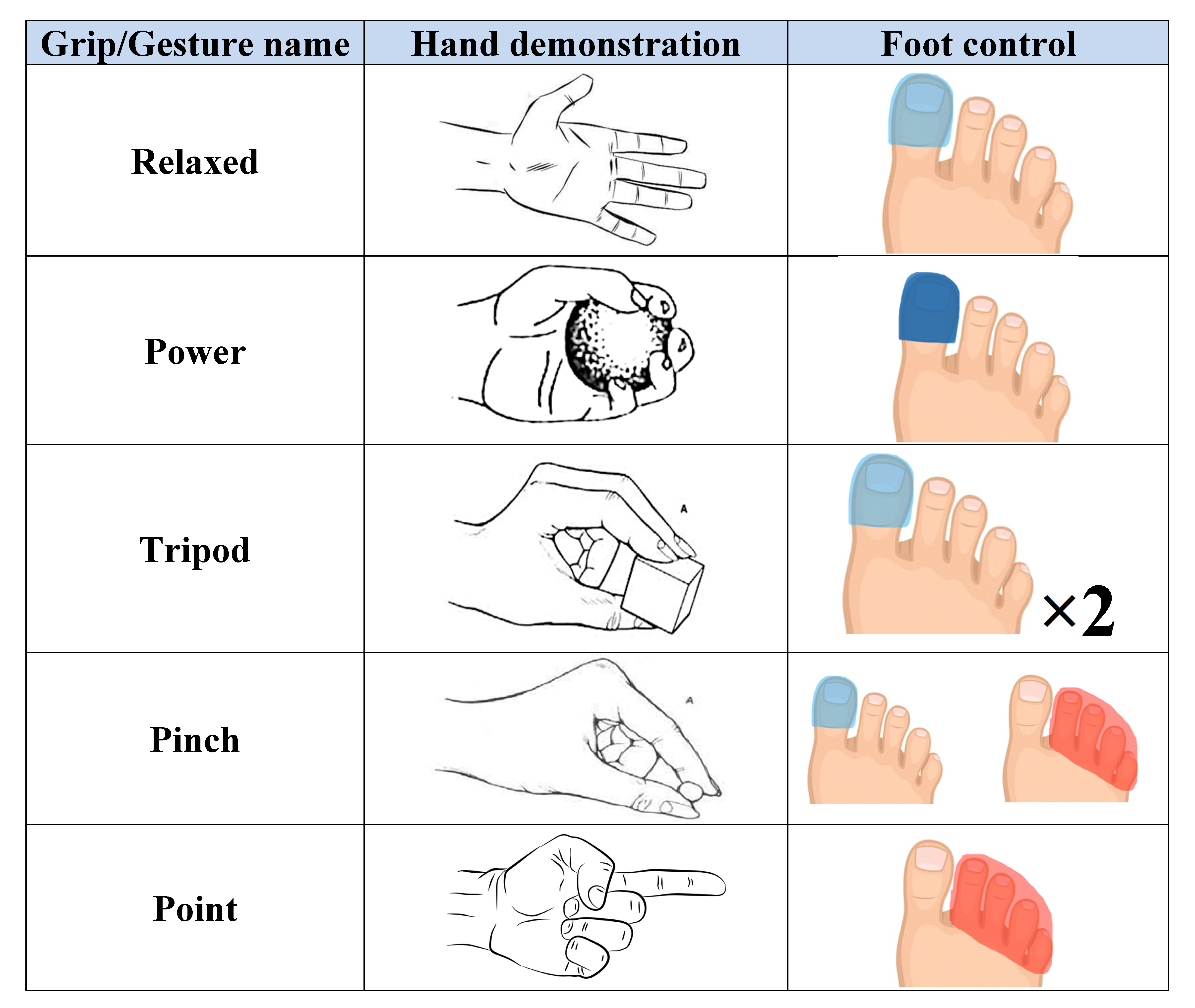
Table 1 shows an example of foot control actions and their corresponding prosthetic arm reactions. Since these reactions are controlled via an editable microcontroller code, any different reactions can be implemented. Figure 4 shows an illustration of the grips/gestures and the corresponding toe clicks.
An alternative approach would be to dedicate the small toes button to switch between the “grip” and “gesture” modes, and the big toe button to select the specific option (for example, pinch, tripod, and power for grips, and thumbs-up, peace sign, and point for gestures). In such a case, the default mode is the grip mode, and only double clicking the small toes button would switch to the gesture mode. With the grip mode active, one big toe click would apply the pinch grip (actuate only the thumb and index), a second click would add the middle finger, making it a tripod grip, and a third click would add the ring and pinky together, making it a power grip. With the gesture mode active, one big toe click would apply the thumbs-up gesture (actuating all fingers except the thumb), a second click would switch to the “peach sign” gesture (actuating all fingers except the index and middle fingers), and a third click would actuate the middle finger, making it a point gesture. A long click on both buttons simultaneously at any time would relax all fingers.
Since walking can result in unintended pressing on the push buttons, the foot controller is intended to be used only while sitting or standing. A walking detection system was developed. This system uses both the accelerometers and gyroscope of the SCU to detect two conditions: (1) if motion above the set thresholds is happening in all three axes of the gyroscope, and (2) if the current state of the foot controller is a “rest” state. The second condition is checked only if the first condition passes its check. If either of these conditions fail their check, the controller will consider the user walking and not ready to use the controller as intended. Once both conditions pass, the controller will set a new rest orientation to be used for subsequent checks. Finally, if the controller detects rapid movement when either of the conditions has failed the check, it pauses checking the IMU signals for 2.5 s and then resumes its normal operation to determine if the user is ready to use the controller to control the prosthetic hand. When the system enters the “movement” state (when walking), the arm would lock its grip until the accelerometers detect the user sitting or standing (going to the “rest” state), and then the signal transmission will be resumed.

2.2. Infinity Arm Design

An overview of existing 3D-printed upper limb prostheses, including the benefits and drawbacks of 58 designs, was presented by Ten Kate et al. [24]. Andrés et al. [25] made a comparison between tendon and linkage prosthetic transmission systems. They concluded that the tendon-driven model achieved a greater quantity of successful grasps compared to the linkage-driven model. Tendon-driven hands are dominant because of the fewer number of parts to be printed, the easier assembly for a nonexpert user, and the advantages in pursuit of lightweight devices. In order to test and demonstrate the developed foot controller, a 3D-printed below-the-elbow prosthetic arm has been designed. This arm, named “Infinity” arm, is meant to be used for gripping lightweight objects, such as a cell phone, a cup, a piece of fruit, a book, etc., or for making hand gestures, such as pointing, thumbs-up, etc. Due to the lightweight limited-torque servomotors used and the material properties of the 3D-printed plastic constructing it, this arm is unsuitable for sports, carrying heavy objects, and performing harsh tasks. Infinity arm has only the degrees of freedom that the foot controller is targeting.
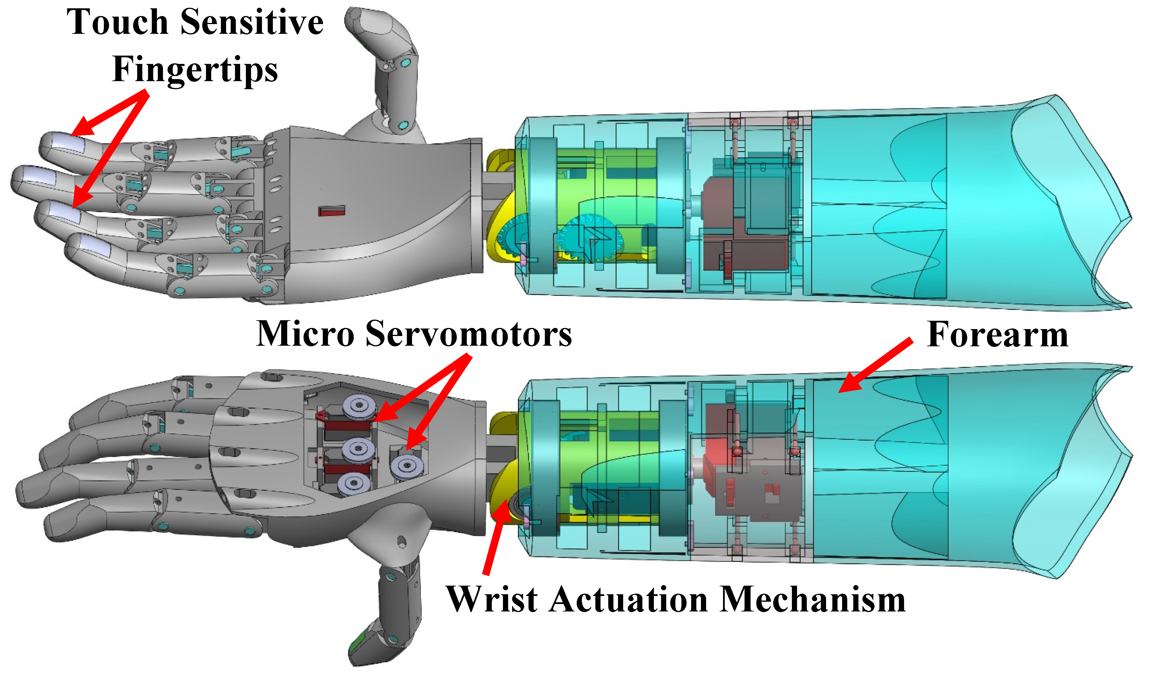
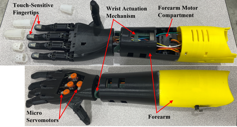
Figure 5 shows the full CAD assembly of the Infinity Arm. The forearm houses the wrist actuation mechanism, which is connected to the palm. The palm includes lightweight digital servomotors that actuate the fingers via tendons. The fingers feature touch sensitive fingertips that are described in Section 2.3.
Both the academic and industrial research communities have tended to place more focus on hand/gripper development than on wrist actuation systems [26]. Montagnani et al. [27] showed that increased dexterity in wrist prostheses may contribute more to manipulation capacity than a highly dexterous terminal device with limited wrist capability. Bajaj et al. [26], in 2019, presented a state-of-the-art review on 1D, 2D, and 3D prosthetic and robotic wrist actuation designs. In 2022, Fan et al. [28] presented another review of artificial prosthetic and robotic wrists evaluating their mobility, stability, output capability, load capacity, and flexibility compared to the human hand.
Infinity’s wrist actuation system is shown in Figure 6. This system uses a PLA central structure which houses two acrylonitrile butadiene styrene (ABS) gears to transfer mechanical torque from a HerkuleX DRS-0201 smart servomotor (stall torque: 24 kg.cm at 7.4 V; max. speed: 0.147 s/60°; resolution: 0.325°; weight: 60 g; size: 45 × 24 × 31 mm). This smart servomotor provides position, speed, temperature, load, and voltage feedback, which can be used to assess the performance of the servomotor in future research. Torque is applied to a bending mechanism that allows the hand assembly to bend by up to 35° in both directions. Rotation is achieved using a 35 Kg DS3235 coreless servomotor (stall torque: 35 kg.cm at 7.4 V; max. speed: 0.11 s/60°; weight: 60 g; size: 40 × 20 × 38.5 mm) placed below the central structure within the forearm. This design, with the addition of two needle bearings, allows rotation of up to 60° in both directions.
Each of the selected servomotors used in the wrist actuation mechanism (HerkuleX DRS-0201 and DS3235) weighs 60 g, which is less than other available and commonly used brushless servomotors that provide the same torque, such as the SPT5835W (67 g) and the BLS-HV35MG (75 g). Since this is a proof-of-concept model to demonstrate the foot controller, the chosen servomotors were preferred. However, a lot of servomotors have standard sizes (40 × 20 × 40.5 mm) and different types of servomotors can replace the proposed ones.
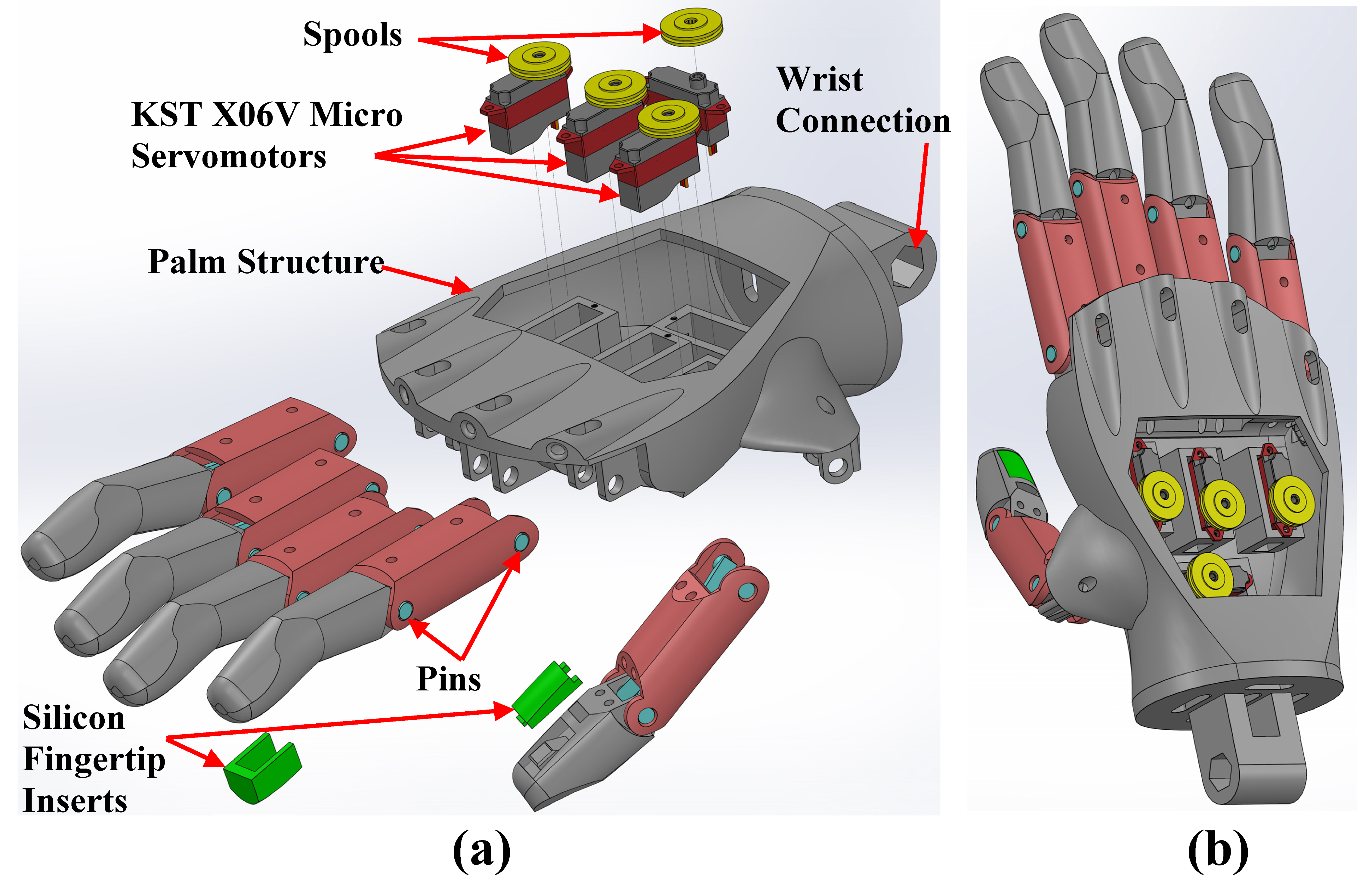
Inspired by the human hand and the previously designed prosthetic arms [29], the shape and size of Infinity’s palm design resembles that of an average male hand. Exploded and assembled views of the palm and fingers are shown in Figure 7. The palm structure has attachment points for the fingers that are secured using pins. Only four integrated KST X06V micro servomotors (stall torque: 1.8 kg.cm at 8.4 V; max. speed: 0.07 s/60°; weight: 6 g; size: 20 × 7 × 16.6 mm) are used to actuate the five fingers, because the pinky and ring fingers are connected to one servomotor and actuate together. These two fingers deform similarly in every grip/gesture of this hand. Finger flexion is produced by the torque originating from the servomotor which rotates a spool mounted on top of the motor. The spool acts as a guide for the actuation wire, having a radius of 6.4 cm, to create the proper amount of displacement as the wire is pulled. These actuation wires are routed through designated pathways inside the finger joints where they are attached to the fingertips. Thus, as the servomotor rotates up to 160°, it actuates the corresponding finger. Extension of each finger is achieved by elastic bands that are routed similarly through the finger joints to allow the fingers to return to a relaxed position. Unlike the human biological structure of fingers which have three phalanges, each finger of the proposed design has two main phalanges to maintain simplicity. The distal and proximal phalanges are made as one part with a slight curvature similar to the relaxed posture of human fingers. The mounting to the wrist actuation system is a slot for a hexagonal pin that would act as a drive shaft and is located at the base of the palm (wrist connection slot).
The thumb and index fingers are actuated in all grips. The middle, ring, and pinky are only actuated in specific grips/gestures. The order in which these fingers actuate is (1) thumb, (2) index, (3) middle, (4) ring and pinky combined. The thumb is actuated first to move the object closer to the palm, then the index is next to grab the object. The other fingers are there to support the object in any way they can. The speed the fingers are being actuated is controlled in a way similar to the bending and rotation system. The only difference is that the fingers’ full range of motion is set on a scale of 0 to 1, where 0 represents 0% and 1 represents 100%. The speed can be controlled by adjusting the percentage value to get to the end point assigned to the set grip inside the loop. A 0.05 (5%) step per loop was found reasonable. This means that a full finger closure can happen in 20 loops (to reach 1 or 100%). With a duration of 20 ms per loop, each finger closure would take 400 ms (0.4 s) to be achieved. Final finger position is preset for each grip during calibration.
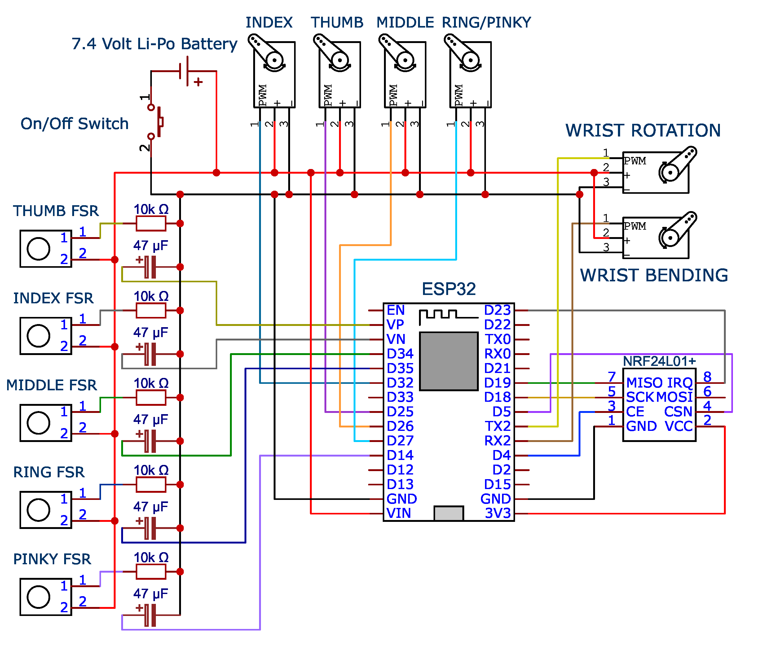
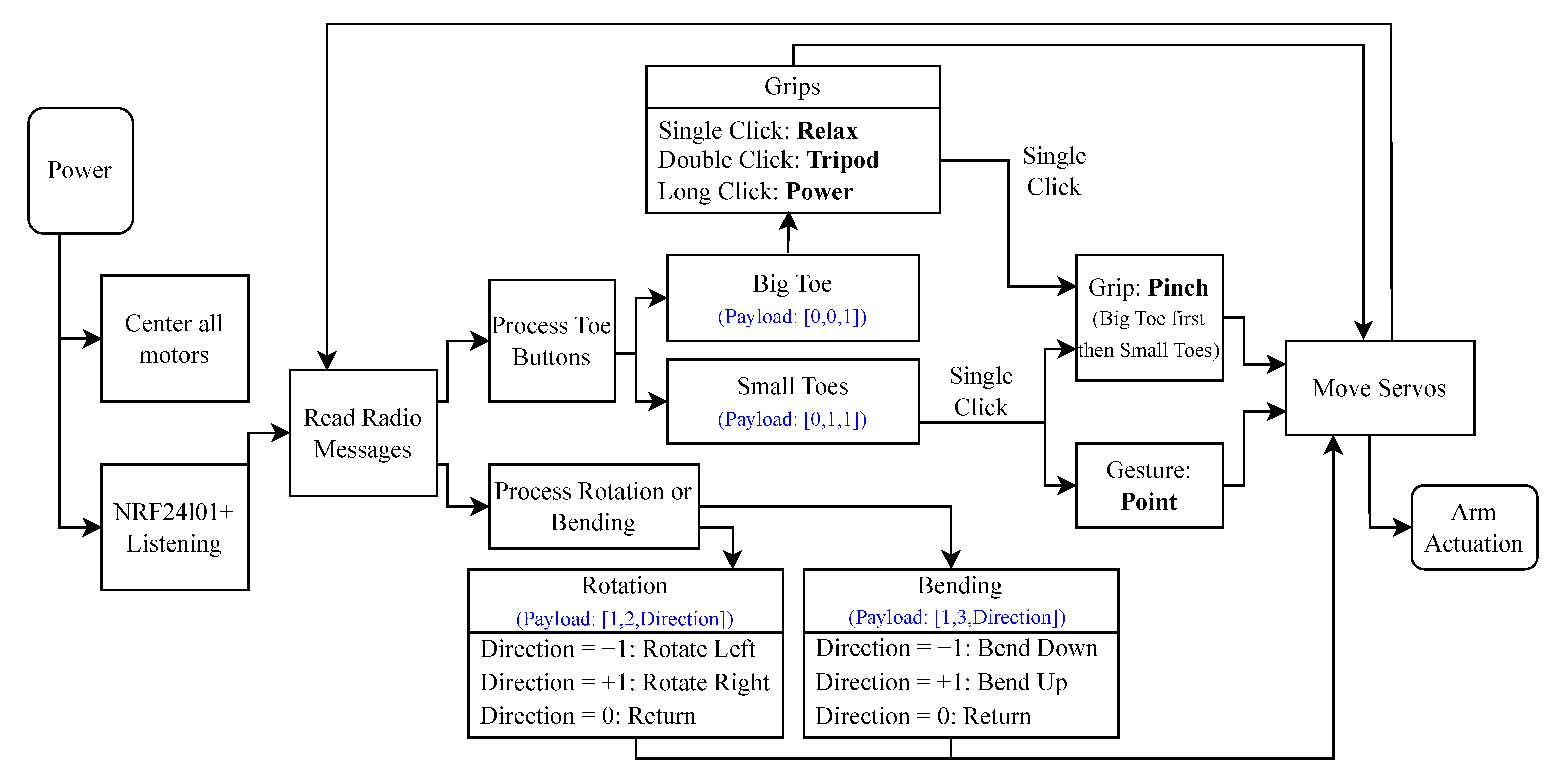
The arm’s architecture diagram is presented in Figure 8, and the arm’s wiring diagram is in Appendix A (Figure A2). Once the arm is powered, it centers all servomotors, and waits for any data transfer. Once data is received as a payload from the foot controller, button presses are used to actuate the fingers according to the identified grip, and bending/rotation data are used to actuate the wrist bending and rotation servomotors in the desired direction. Specially for the big toe button presses, the code identifies if it is a single, double, or a long click, to engage the correct grip.

2.3. Infinity Haptic Feedback System Design

Sense of touch is one of the primary deficits reported by individuals with limb differences [30,31]. Nemah et al. [32] presented a review of non-invasive haptic feedback stimulation techniques for upper extremity prostheses. Rosenbaum-Chou [33] performed a study to evaluate the benefit of integrating a vibratory haptic feedback system for upper-limb prosthetic users. It was found that haptic feedback improved the grip force accuracy by 129% and 21% for light (2 lb) and medium grip (10 lb) force targets, respectively. The participants provided specific positive examples of how the vibratory haptic system was useful in everyday tasks at home. Similarly, Kim and Colgate [34] showed that haptic feedback enhances grip force control of sEMG-controlled prosthetic hands. Next-generation prosthetic hands would possibly include haptic feedback systems to provide users with a sense of touch and improve controlling the device.
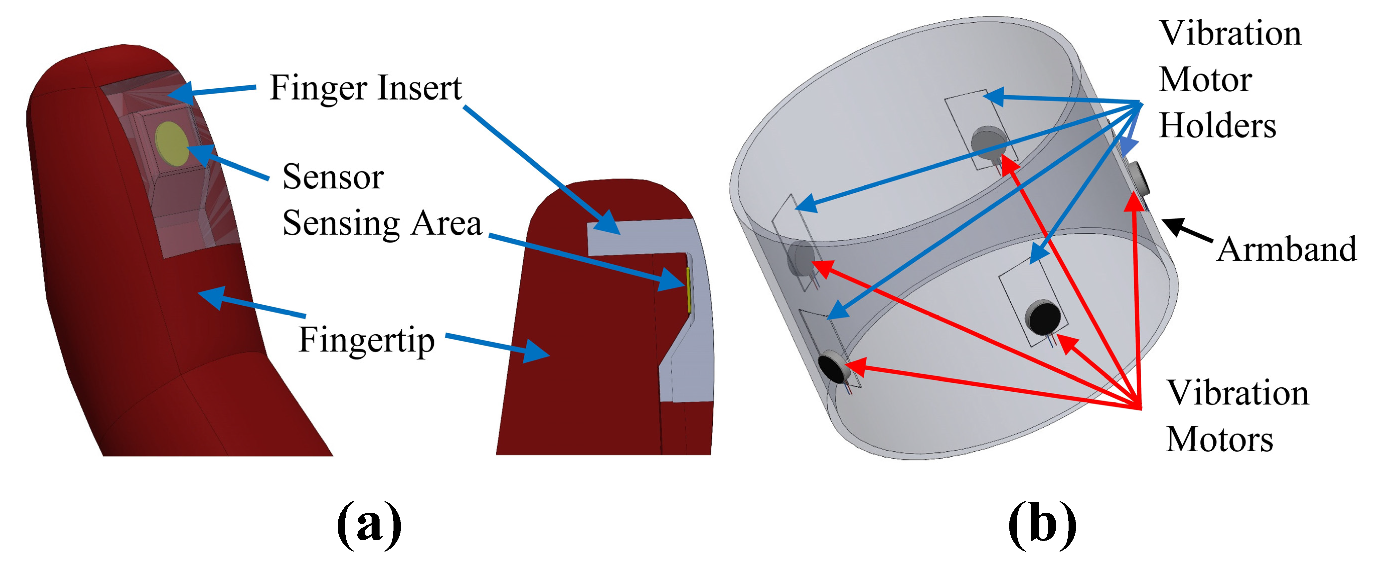
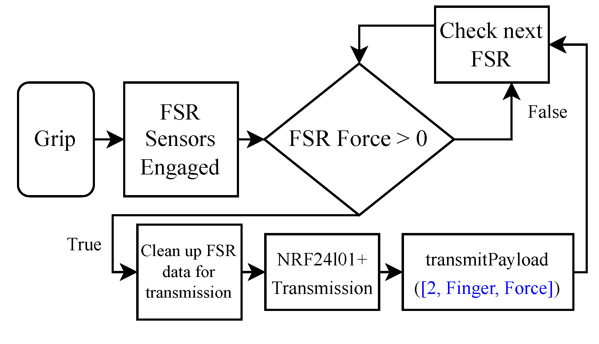
Figure 9 shows the Infinity haptic feedback system, which consists of fingertip force sensors (sensing subsystem) and the sensory feedback armband (feedback subsystem). A TekScan A101 mini-force sensor resistor (FSR) is located within each of the five fingertips. This sensor can measure forces up to 44 N (equivalent to 4.54 kg or 10 lbs), and its operating temperature is −40–60 °C. Each sensor is placed underneath a silicone insert that secures the sensor inside the fingertip to provide a seamless design, as shown in Figure 9. This design improves the grip by increasing the friction between the silicon insert and the object being gripped, while allowing the applied force on the finger to be transferred to the sensor. The fingertip force signals are transmitted via wires that run through the fingers, palm, and forearm to the main electric circuit of the arm. Then, they are transmitted wirelessly to the armband as a payload of [2, Finger, Force], where “Finger” indicates the finger that touched an object (1–5) and “Force” is the measured value of the sensor. The architecture diagram of the sensing subsystem is shown in Figure 10. A loop runs to check if the measured force of the first sensor exceeds 0. If not, it goes to the next sensor. If any sensor force exceeds zero, the data is transmitted as a payload. The wiring diagram of the arm in Appendix A (Figure A2) includes the fingertip force sensors.
The feedback subsystem contains an elastic armband with integrated mini vibration motors (Figure 9b) and an “electronics box”. The armband is to be secured around the user’s upper arm or residual limb, and the electronics box is to be clipped to the armband. The electronics box contains an ESP32 microcontroller, an nRF transmitter, a rechargeable lithium-ion battery, a charging module, a 5-pin JST connector, a slide switch, and a push button. Up to five vibration motors, corresponding to the five fingertip force sensors in the hand, can be used. In the proof-of-concept model that was built, only four vibration motors were implemented corresponding to the thumb, index, middle, and ring/pinky fingertip force sensors, because as the number of vibration motors increases, identifying the location of the vibration source on the upper arm gets harder. The vibration intensity of each motor reflects the amount of force applied to the sensor (transmitted wirelessly using the payload protocol), but the user can press on the push button to reduce the vibration intensity from High (100%), to Medium (66%), or Low (33%), in case the high intensity is uncomfortable. The DZS Elec mini vibration motors (Speed: 12,000 rpm, voltage: 3 V, weight: 0.8 g each) were used in the manufactured model. The JST connector enables the separation of the electronics box from the armband to recharge the battery. The vibration motors are placed in holders or pockets sewed in the armband, so that they may be removed if the user wants to wash the armband. The vibration feedback signals can be applied in different patterns or durations. For example, pulses of one-second vibrations can be applied every ten seconds as long as the fingers are in contact with an object. The architecture diagram of the feedback subsystem is in Figure 11. Once data are received by the nRF module, the fingers being triggered and the force amplitude applied to each of them are identified from the payload. In addition, the button status in the electronics box is checked to identify the desired vibration level to be multiplied by the force amplitude. Finally, the vibration motors corresponding to the triggered fingers are activated to vibrate in the armband with the desired intensity following the predefined vibration pattern. The wiring diagram of the electronics box can be found in Appendix A (Figure A3).

3. Results

3.1. Manufacturing and Assembly

All structural components were 3D-printed, servomotors were secured to their housings, and force sensors were inserted in their assigned location in fingertips and secured with the silicon inserts. Tendons were routed through the fingers and wound around the spools on the servomotors (or alternatively tied to servo horns), finger digits were assembled to the palm structure using pins, and all electrical wires were connected to the main circuit board. Table A1 in Appendix B is a bill of material that includes all main components used in the proof-of-concept models of Infinity foot controller, arm, and haptic feedback system. Figure 12 shows the manufactured prototype of the Infinity arm. The total weight of the arm without a socket is 0.72 kg (1.6 lbs), and the manufacturing cost is $523.
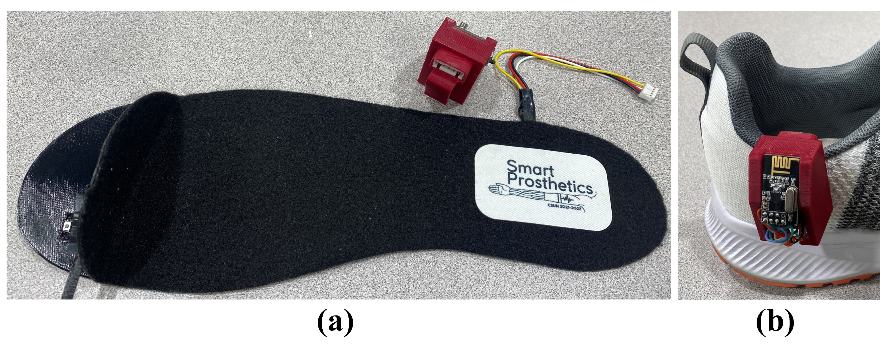
The TPU layer and the PLA paddles of the foot controller were 3D-printed, then the push buttons were secured in their assigned housings in the TPU layer, and the wires were routed through their channels. The silicon and fabric layers were then bonded to complete the insole controller. The SCU housing was also 3D-printed, and all its electronic components were secured in their assigned positions. Figure 13a,b show a manufactured insole controller with the SCU and a shoe with the insole controller placed inside it and the SCU clipped to its side.
Figure 14a shows the location of the four mini vibration motors on the manufactured proof-of-concept adjustable armband. Three of these motors were placed at the upper section of the upper arm, and only one was placed at the lower section, since preliminary testing by the developers showed that vibrations at the upper section are more identifiable than at the lower section. However, the locations of the vibration motors can be customized if a grid of pockets is sewed to the armband interior. The electronics box, shown in Figure 14b, was 3D-printed and all components were connected and secured in their positions.
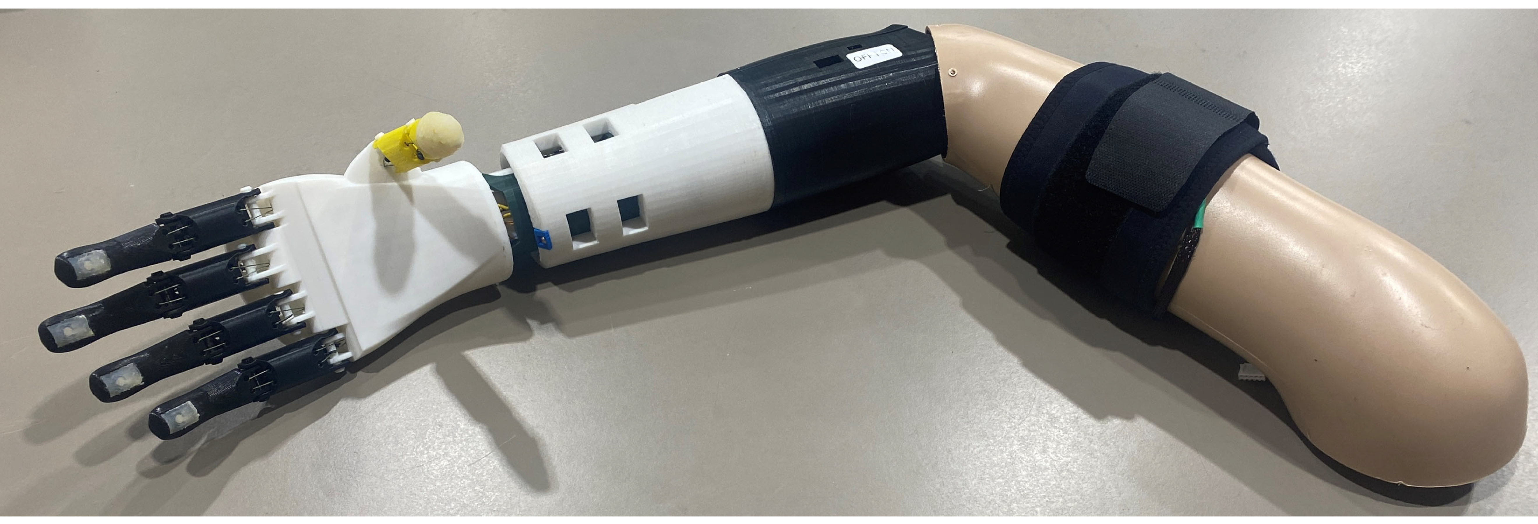
Figure 15 shows a demonstration of the Infinity prosthetic arm connected to a mannequin’s upper arm with the sensory feedback armband.

3.2. Actuation and Gripping Tests

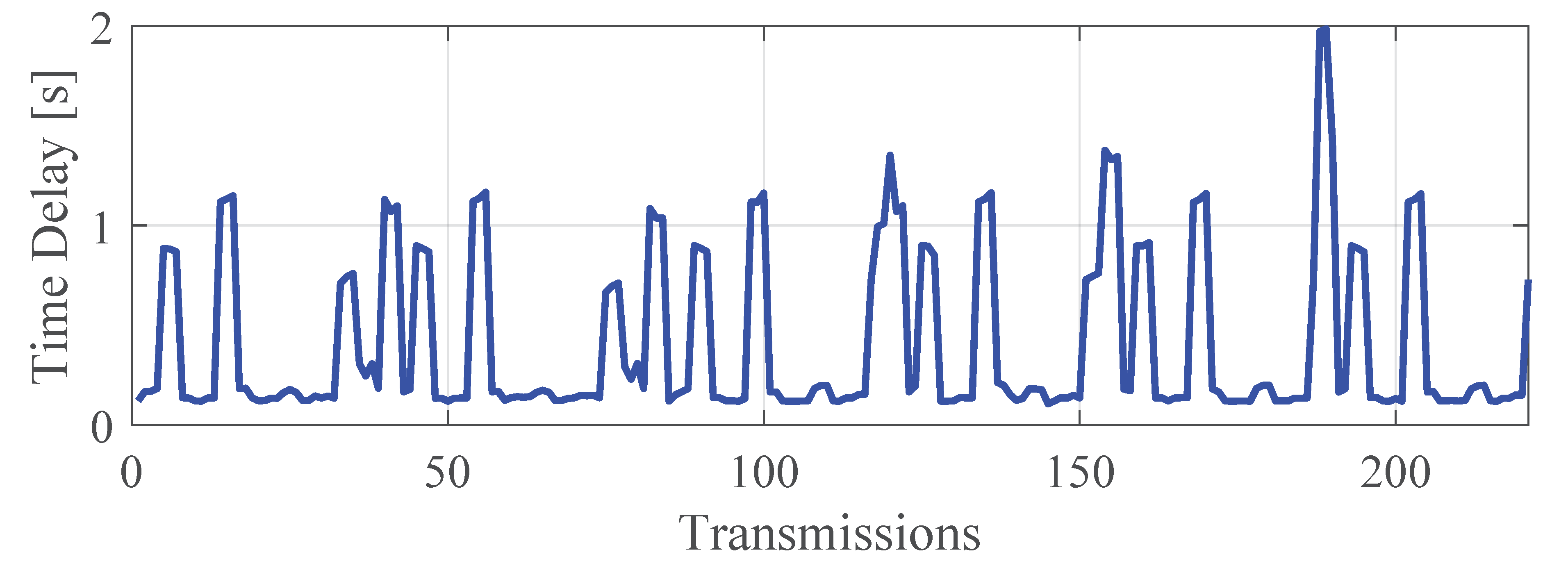
To measure the speed of data transmission between the foot controller and Infinity Arm, both the foot controller’s Seeeduino microcontroller and the arm’s ESP32 microcontroller were connected to the computer via USB cables. A MATLAB code was developed to read the data sent from the foot controller, and the data received by the ESP32. The code then calculates the delay time and compares the transmitted values. Tests were done focusing on specific control signals for a duration of 30 s. Average time delays were found to be 0.41 s, 1.03 s, and 1.65 s for rotation, bending, and push buttons, respectively. The most common time delay was found to be in the range of 0.11–0.35 s, 0.01–0.63 s, and 1.42–1.95 s for the respective control signals. Figure 16 shows a sample time delay for the wrist rotation data transmission, including 220 data points. These time delays are very satisfactory for a proof-of-concept model. Other data transmission methods, such as Bluetooth, could reduce these delays and would possibly be considered in future iterations.
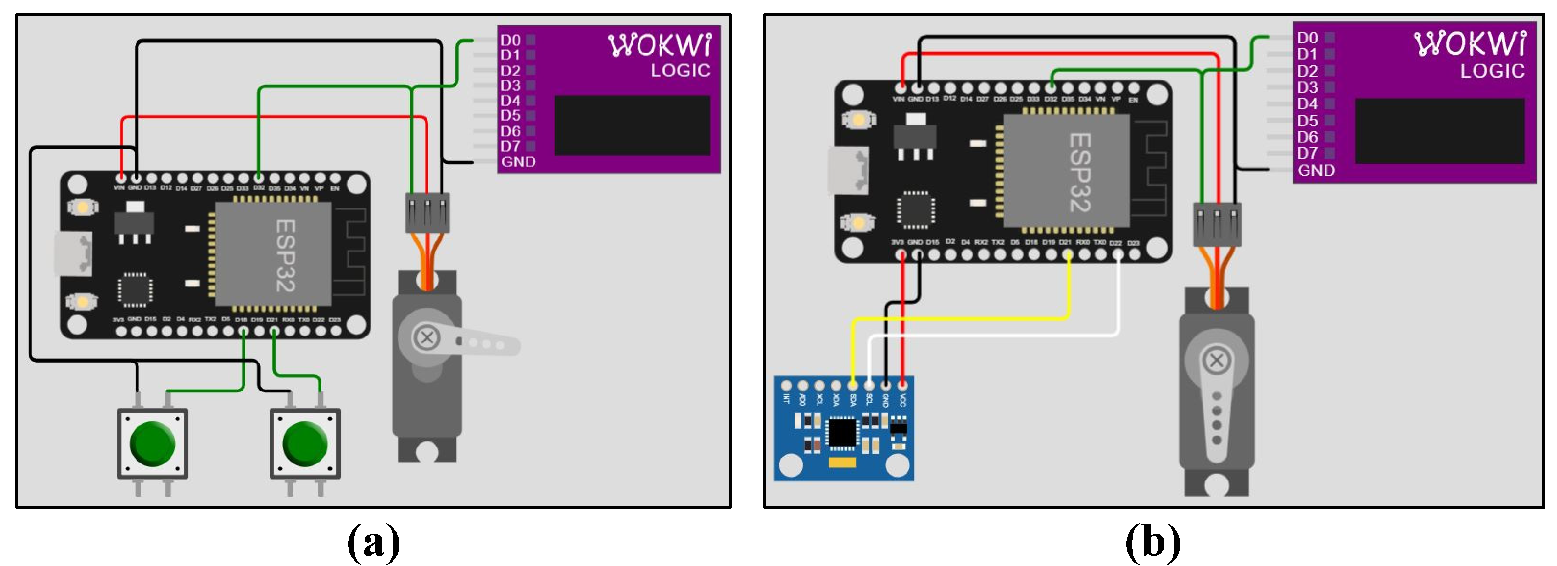
To evaluate the performance of the developed electric circuits and the microcontroller code, simulation models were created on “WOKWI Logic” simulator for push buttons and gyroscope connected to ESP32 that actuate a servomotor, as shown in Figure 17. The push buttons represent those integrated in the foot controller’s insole, and the gyroscope represents the bending or rotation gyroscope in the SCU’s Seeeduino microcontroller. The servomotor connected to the push button represents any of the servomotors in the palm of the prosthetic hand, and the one connected to the gyroscope represents either the bending or the rotation servomotor in the wrist actuation system.
A testing setup, shown in Figure 18, was also designed to characterize the response of the wrist actuation system to foot control signals. The setup includes a mount for a testing servomotor with an attachment unit for the foot controller. The RDS3235 coreless digital servomotor was used with a U-shaped aluminum bracket. The attachment unit has two clips, one for the wrist bending test and the other for the wrist rotation test. A separate ESP32 controller was connected to the testing servomotor to rotate the attached foot controller in both directions in a sinusoidal pattern. Video S4 in the Supplementary Materials shows the bending and rotation tests. A ±45° foot controller rotation resulted in achieving the full range of wrist rotation and bending, following a similar sinusoidal pattern, which was satisfactory for the developed proof-of-concept model.
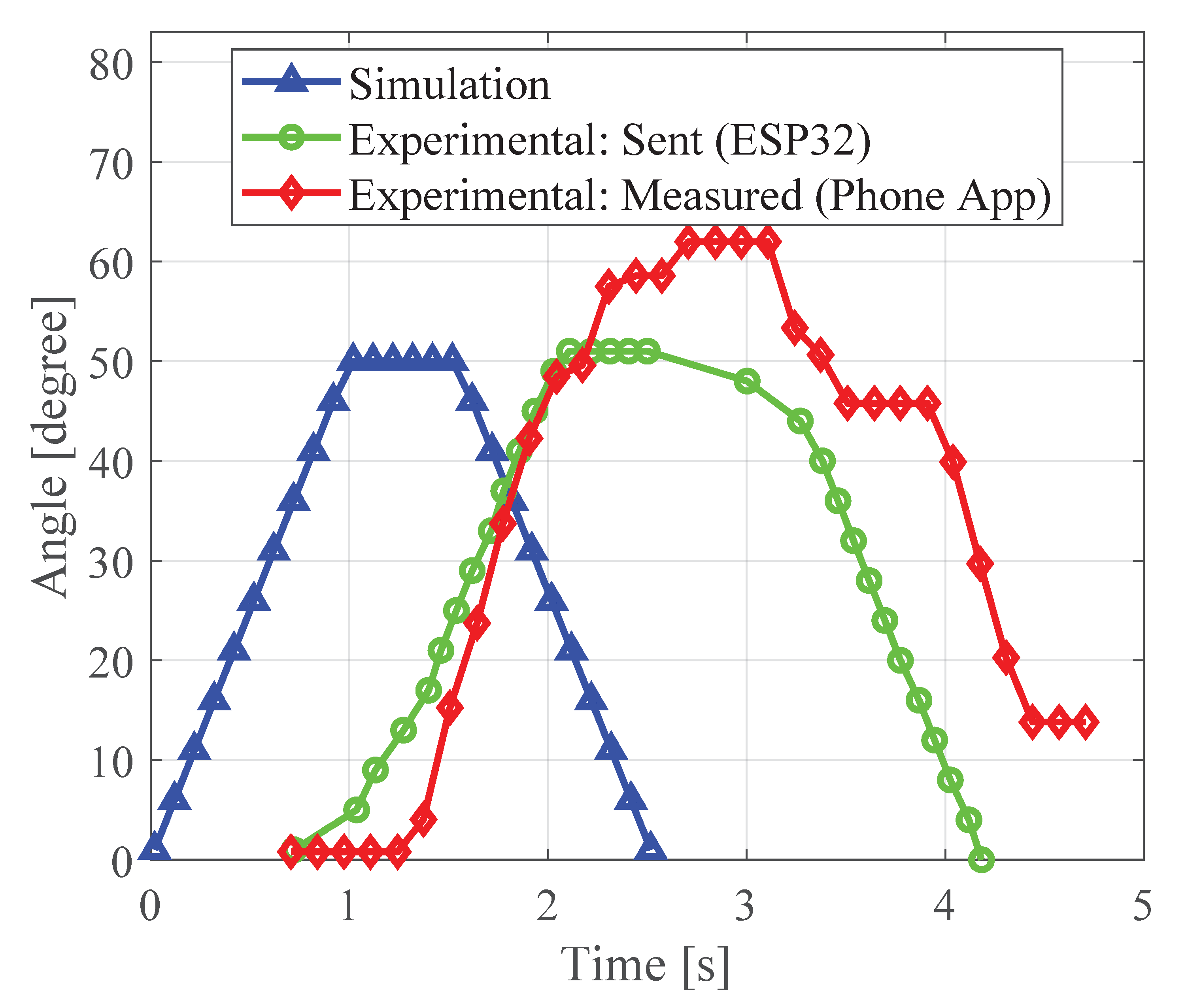
To measure the achieved wrist rotation angles, a cell phone was secured to the arm, as a preliminary testing setup for this proof-of-concept model, and an application called “Arduino SJ” was used to record the arm’s rotation measured using the phone’s built-in compass sensor. In addition, the ESP32 microcontroller in the arm was connected to a computer to record the data received from the foot controller and sent to the wrist actuation system via the developed MATLAB code. Figure 19 shows a comparison between the simulation and the experimental wrist rotation data in a sample half cycle rotating 50° in both directions. The simulation data reflects a perfect environment. An initial 0.6 s time delay can be seen in the experimental data sent to the arm rotation servomotor by the ESP32. There is also a similar time delay before the start of rotation in the opposite direction. These time delays happened during the transfer of data from the foot controller to the arm as mentioned earlier. The slope of the experimental curve is very similar to that of the simulation curve, indicating a similar rate of rotation. Also, the highest angle achieved is almost identical to the simulation data. The experimental data measured using the phone placed on the hand has some slight initial delay and a significant overshoot that is possibly due to the inertial effects from the added mass of the phone on the hand. The slope of the curve is almost identical to the other two curves, indicating a similar rate of rotation, despite the irregularities of the curve, especially during the wrist’s back rotation. The Video S1 shows how the wrist motion consistently follows the foot controller’s motion. Similar results were obtained for wrist bending and finger actuation (omitted here for brevity), indicating a well-designed circuit and microcontroller code, with consideration of the expected data transmission time delays.
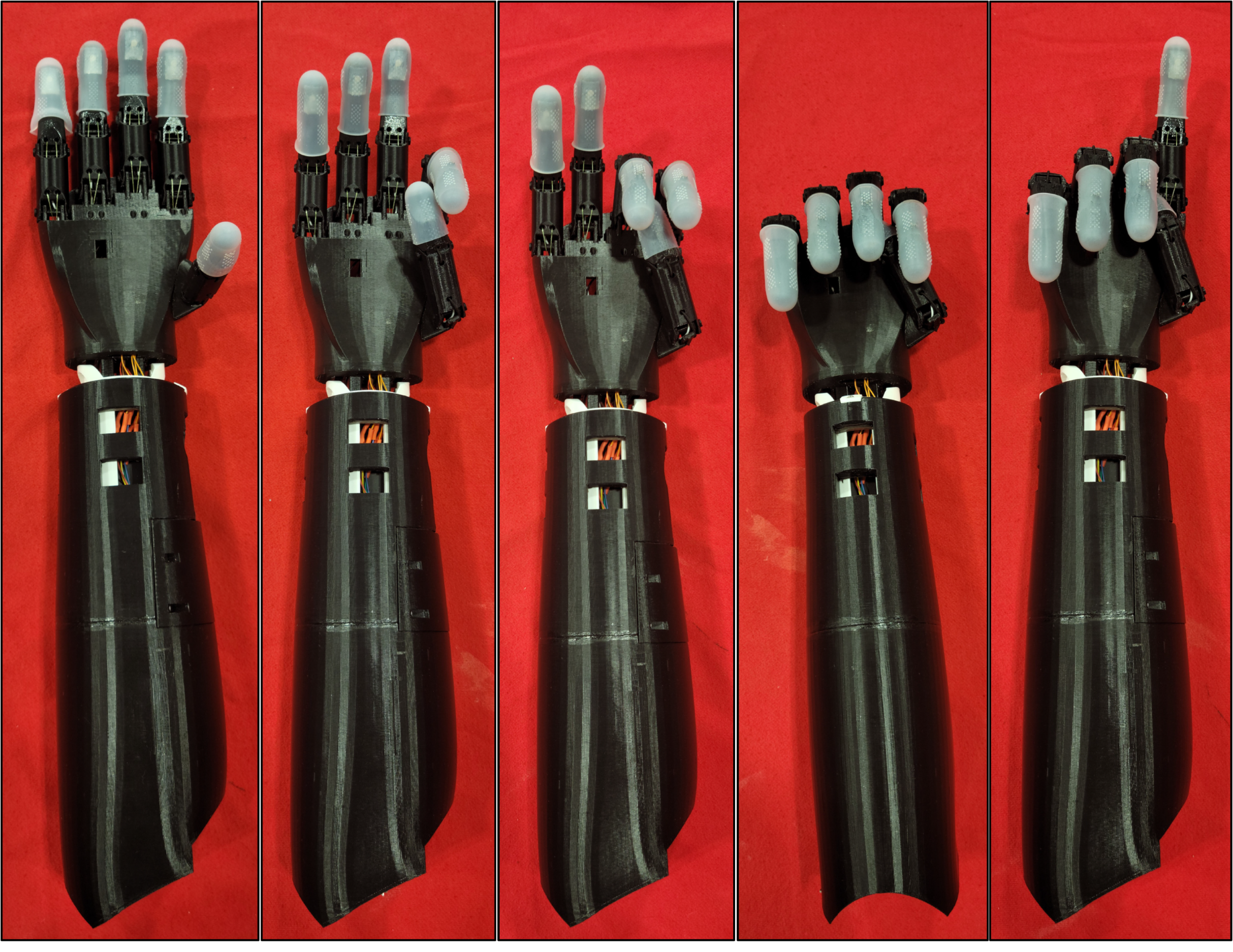
Figure 20 shows the manufactured proof-of-concept Infinity Arm model performing the five finger grips/gestures it was programmed to do as a result of foot control commands as in Figure 4. Rubber fingertips have been added to increase the friction between the fingers and the objects to be gripped. The arm’s performance in terms of applying grips matched exactly all foot control signals in all tests.
The force applied by each individual finger was measured using a hydraulic pinch gauge and a digital weight scale. The average fingertip force was 65.7 g/0.645 N, which is only 53% of the theoretical force, F, expected by the KST X06V servomotor when operating at its lowest voltage and torque, T, and considering a torque arm, r, of 6.4 cm, which is the spool radius (F = T/r = 800 g.cm/6.4 cm = 125 g). This indicates that force transmission has some losses that can be addressed in future iterations of the arm. A full hand gripping test was attempted using a BASELINE digital hand dynamometer. Unlike human hands that can adjust the fingers around the dynamometer’s handle to ensure the strongest grip, it was a challenge to orient the prosthetic hand properly around the handle to measure the strongest grip. A relatively low grip force of 1.5 lbs/6.67 N was measured. Finally, an exercise handle was attached to a force gauge, and the hand was wrapped around the handle to measure the pulling force from a power grip. An average pulling force of 13.3 N was measured, which indicates that objects as heavy as 1.36 kg can be carried by this arm.
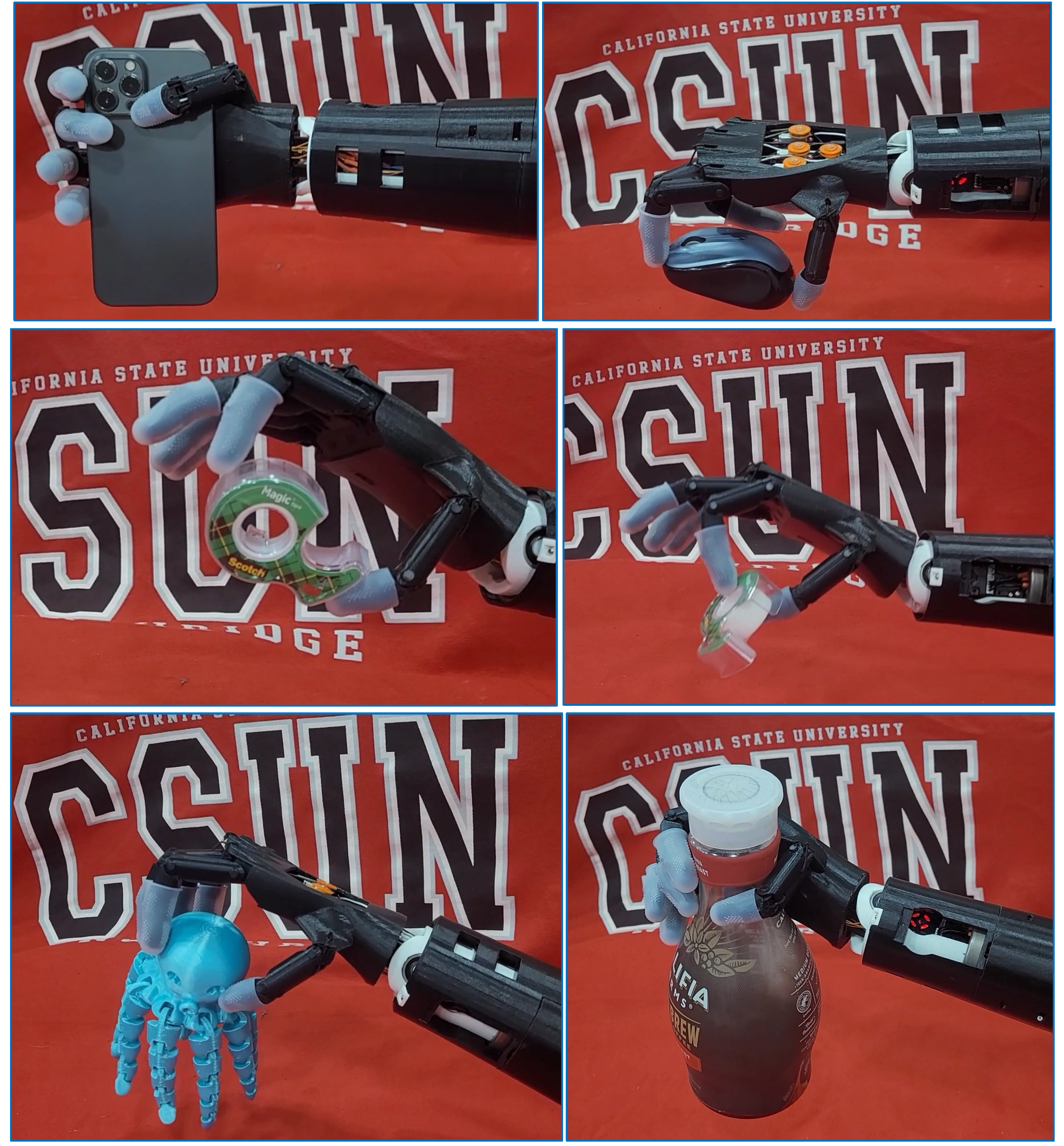
Figure 21 shows examples of the Infinity Arm model gripping different objects of different weights, shapes, and sizes (a cell phone, a wireless computer mouse, an adhesive tape dispenser, a 3D-printed spherical object, and a full juice bottle). Other objects tested included a pencil, a book, wooden blocks, cups, and plates. Videos S2 and S3 in the Supplementary Materials show the arm gripping a variety of objects. It can be seen that the fingers can effectively adapt to the shape of the object it grips. The success of the grip depends on the hand orientation around the object, the extent of contact between the hand and the object, and the material of the object. Speed of finger deformation was adjusted after the initial tests. The high speed that was used initially made it challenging to grip smaller objects since the first finger that touches the object can push it away before the other fingers surround it to grip. Lower speeds of finger deformation applied in sequence, as was described in Section 2.2, proved to improve the chances of successful grips.
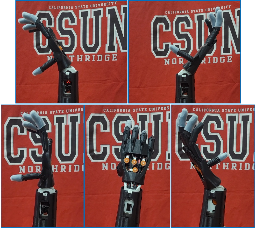
Figure 22 shows the foot movement that causes wrist bending and rotation shown in Figure 23. Initial tests helped in adjusting the parameters that control the speed of rotation and walking detection that were mentioned in Section 2.1. The videos in the Supplementary Materials also show the arm bending and rotating. During operation, the frequency and intensity of the noise coming from the servomotors were recorded. The frequency was found to be approximately 23 Hz, and the intensity was around 24 dB.
All vibration motors integrated in the sensory feedback armband vibrated upon applying pressure to the fingertip force sensors, and the push button in the electronics box successfully adjusted the vibration level from High to Medium or Low. The Supplementary Materials includes Video S4 demonstrating the proposed haptic feedback system.

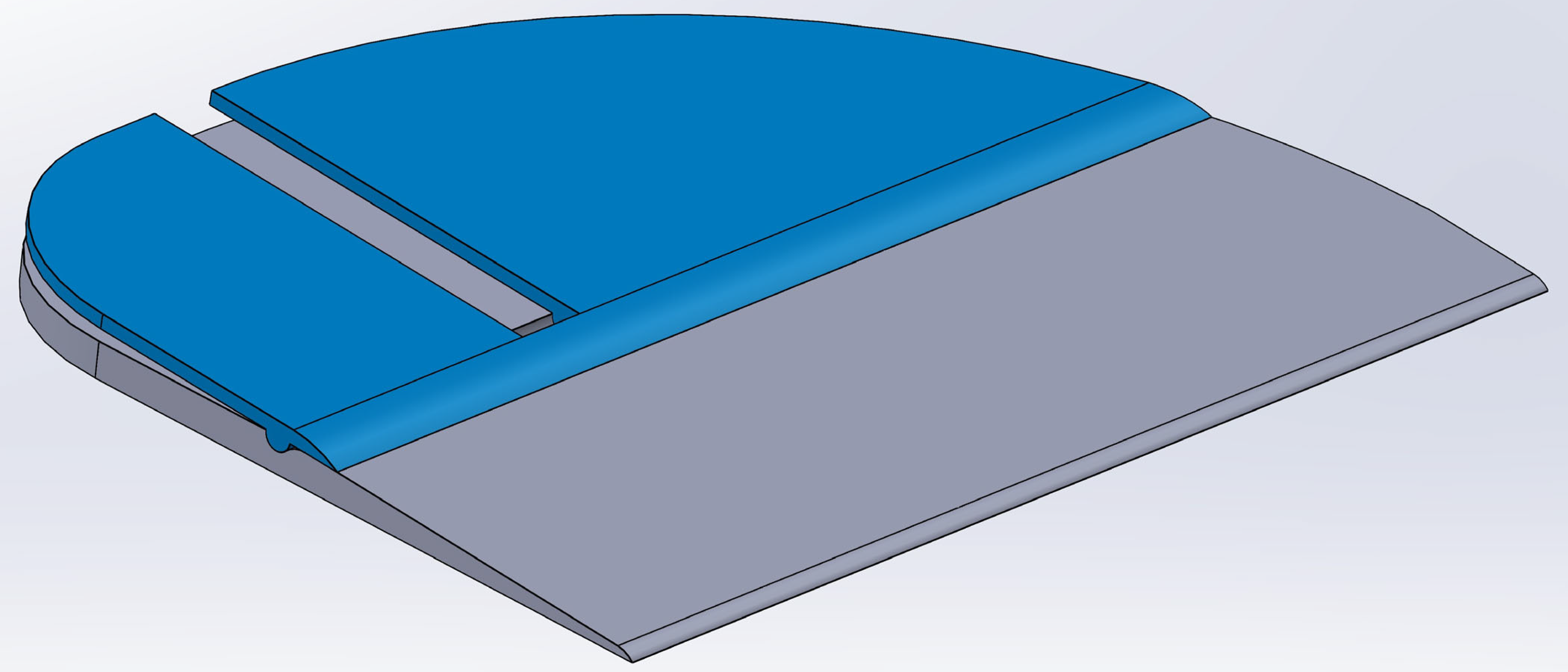
3.3. Foot Control Training System

A training system was prepared to help users master utilizing the foot controller to move the prosthetic arm and perform daily tasks in a short time, even before the physical arm is fitted to them. The system includes a training platform similar to the front part of the foot controller insole, as shown in Figure 24, with two push buttons under the paddles. The platform is connected to an electric circuit that has two LED lights to be placed on a table in front of the trainee during the training sessions. The platform is also connected to an Arduino microcontroller that sends all button presses to a script that is read by a MATLAB code. To start training, the trainee would sit on a chair and place their foot on the testing platform, then watch the screen that shows the commands that the trainee is supposed to perform with their toes on the platform. Each of the two LED lights corresponds to one push button in the training platform. The function of the LED lights is to help the trainee ensure they are clicking the right push buttons, without looking at their feet. Each training session has three phases, following an initial free practice time. The instructions on how the foot controller would activate each grip, as shown in Figure 4, would first be presented to the trainee. The trainee would also receive a hard copy of this figure in case they need to recall how to activate any grip during the training session.
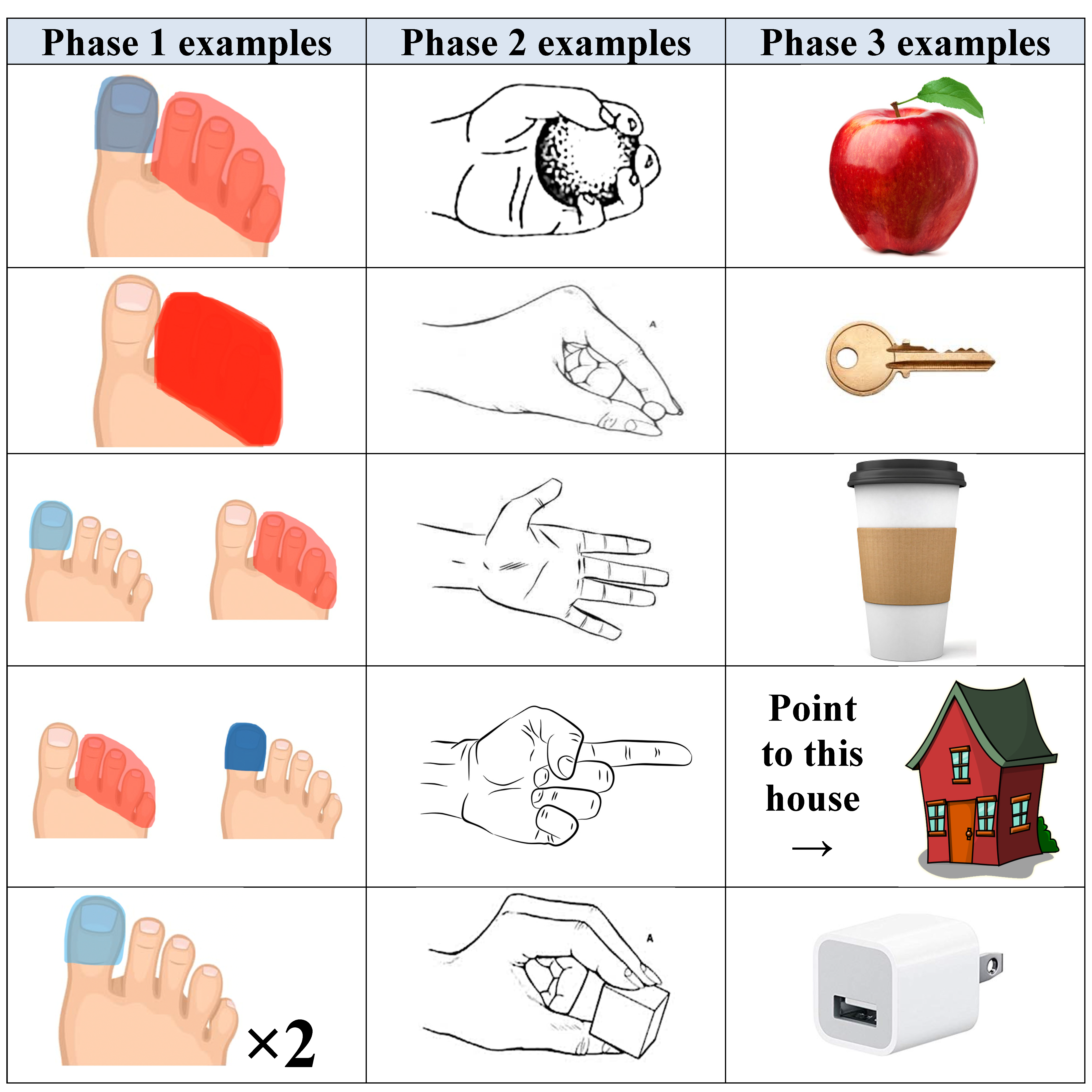
During the initial free practice time, the trainee can try any grip pattern, check that the LED lights are representing the push button presses, and become familiar with the whole system. Phase 1 is a sequence of figures that represent tasks the trainee should do by pressing the paddles with their toes, as shown in the examples in the first column in Figure 25. The light blue and red colors represent single clicks with the big toe and the four lesser toes, respectively. The dark colors represent long clicks, and “×2” symbol means repeat two times. If there are two pictures in the slide, as in the third and fourth rows, the commands should be done in sequence from left to right. The MATLAB code compares the received data from the platform to the pre-saved model answers and calculates the score whenever the trainee wants to check their success rate.
Phase 2 does not show the trainee any pictures of toes as in phase 1 but shows pictures of a human hand doing one grip per slide, as shown in the examples in the second column in Figure 25. The trainee in this phase would have to translate each hand grip picture in their mind into a toe command, so it is more advanced than phase 1. Phase 3 gets even more challenging by showing the trainee pictures of real-life objects, as shown in the examples in the third column in Figure 25. The trainee would have to select a suitable grip that would be successful in gripping the object and translate this into a toe command. Some objects can be gripped using more than one grip. For example, the wall charger block, shown in the last row in the third column, can be gripped using pinch, tripod, or power grips. The MATLAB grading code would consider all possible grips acceptable. However, the apple or the cup would need a power grip to ensure a secure grip. After each of these examples, a slide would ask the trainee to release the object, which would require the relax hand posture. The training is customized, so each trainee can repeat any phase multiple times or start from a more advanced level. The code also displays encouraging messages or feedback messages based on score history and mistake type and frequency. Example messages include “Good job, keep it up!” and “Excellent work! You mastered it!” for improved performance, “Keep focusing on your toes and do not rush!” and “Maybe a quick refresher would be useful now” for declining performance or specific repeated mistakes of the same type.
Preliminary testing by the developers of the training system (a subgroup of authors) helped select the easiest and most intuitive foot controller action for each hand function, which are shown in Figure 4. The developers voluntarily consented to try the system just to guide the design choices. The following conclusions were also drawn: (1) in general, a person can reach a very high level of control when using Infinity’s foot controller after the first 5–10 minutes of training, (2) performance in using the foot controller improves quickly with longer training times and more training sessions, (3) pressing buttons with the big toe is the easiest, followed by the other four toes moving together, since moving an individual lesser toe is way more challenging, (4) receiving feedback (audible and/or haptic) from the push buttons helps improve the user’s performance and confidence. Training results of human subjects of different age, race, and gender would be collected and analyzed in future studies. Practicing wrist bending and rotation can also be included in the training. The training system can also be extended to include a simulated or a virtual arm that the user can see moving during the training.

4. Discussion

4.1. Comparison between Infinity and DEKA Foot Controllers

It is important to highlight the differences between Infinity’s foot controller and DEKA’s foot controller [22,23].
  • DEKA’s foot control design is intended to be implemented underneath the insole of a shoe whereas Infinity’s insole controller is placed on top of the insole or as a replacement of the user’s shoe insole.
  • Infinity design uses two push buttons strategically placed underneath the big toe and the four lesser toes. Paddles are placed above these push buttons to increase the surface area of the push buttons for easier control by the user. In addition, the combination of the push buttons and paddles allows for audible feedback to the user as well as haptic feedback to the user’s toes. This allows the user to gain instant feedback of the commands they are sending to the prosthetic arm. On the other hand, DEKA’s design has only pressure sensors that give no audible or haptic feedback.
  • In DEKA’s foot control system, motions of the prosthetic arm are solely based on differences in force or pressure of the user’s foot, whereas Infinity’s design focuses on different commands implemented by the two push buttons under the toes, such as single click, double click, long click, and combination clicks.
  • In Infinity, control of the prosthetic arm gripping actions is localized under the toes which are the body parts that humans can control the most and easiest in their foot. On the other hand, DEKA’s control has force sensors spread all over the place under the foot, which might be more challenging to press.
  • Both systems include IMU functionality (which contains a gyroscope and an accelerometer) to measure the orientation of the user’s foot or its acceleration. These signals can be used to bend or rotate the wrist of the prosthetic arm if such degrees of freedom are available. The system is programmed to disengage when the user starts walking. However, the placement of the IMU is different in these two designs: in DEKA’s design, the IMU is placed on top of the user’s shoe, while in Infinity, it is placed on the side of the user’s shoe. Accordingly, the translation of data to different functions varies between the two designs. The authors believe that the side of the shoe is a better location for the IMU than the top, because it will not be as noticeable as it is on the top of the shoe.
  • DEKA patents state that there may be at least one or more CPU within the system to translate input data from the sensors to the prosthetic arm. The CPU can communicate with the prosthetic arm via wired connection or wirelessly. Infinity includes a compact 3D-printed sensor-controller unit that includes the IMU integrated in a microcontroller, a rechargeable battery with its charging unit, an On/Off power switch, and a wireless transmitter. The structure of this unit has been designed to house all these components in the smallest possible footprint that clips on the side of the user’s shoe.

4.2. Foot Controller Limitations

Seneviratne et al. [35] presented a survey on wearable devices and the challenges faced in designing them. Infinity’s insole controller, presented here, is a proof of concept. It can be redesigned to be waterproof, but this was not the main objective of this research. Some types of sandals have straps, and with those, both the insole and the SCU can be used as in the case of a shoe. Barefoot users will have to put on any type of shoe or socks to enable the insole to be placed under the foot and the foot controller to be clipped around the ankle, in order to use this system. Exactly like any other device, the Infinity Foot Controller will experience normal wear-and-tear depending on the usage. In such a case, replacement units would be needed.
Similar to other wearables, the proposed sensor controller unit is powered by a battery that needs to be recharged regularly. The foot controller draws a maximum current of 0.0112 A which gives the foot controller, with the selected 400 mAh battery, a run time of 40 h of use. When the foot controller is in standby mode, it draws only 0.008 A, which gives the controller a run time of 50 h. The recharge time is about 2 h. Users will be expected to have multiple SCUs so they can use charged units while replacements are being charged. Further development of battery technology would increase the usage time. Data transmission security was not in the scope of this work but can be included in future developments.
Exactly like any other device or wearable, not all designs would work well with all people. So, the foot controller limitations can be listed as:
(1)
The user should be able to move their toes to click with the big toe or the four lesser toes;
(2)
The user should be sitting or standing to control the arm. Walking can result in unintended pressing on the push buttons, so once detected, the arm will go to a “freeze” mode and stays on its posture, whether gripping an object or not, until the “rest” state is retrieved;
(3)
The battery needs to be recharged regularly depending on the usage (a replacement battery can be used while recharging the replaced one);
(4)
Regular wear-and-tear can happen to the foot controller or the SCU depending on the usage, and replacement units can be used;
(5)
The distance between the foot controller and the arm should not exceed 5 m to maintain reliable connection. Given that both wearables are supposed to be on the body of the user, this distance would not be reached in normal operation.

4.3. Infinity Arm Design Limitations

As mentioned earlier, the Infinity Arm was designed to test and demonstrate the developed foot controller. Hence, its degrees of freedom are limited to the motions targeted by the foot controller. The arm is also only suitable for gripping relatively lightweight objects and performing relatively simple tasks due to the limitations of the torques generated by the chosen servomotors in the palm and the material properties of the 3D-printed plastics used, which may fall short of what prosthetic users may expect or require from an upper limb prosthetic device.
The movements of the hand can be categorized into two main groups: (1) prehensile movements that involve seizing and holding an object partly or wholly within the compass of the hand; and (2) nonprehensile movements that involve no seizing or grasping [36,37]. The current design of Infinity allows for three prehensile movements (power, tripod, and pinch) and one nonprehensile movement (point). More movement patterns can be added if more input signal patterns, such as double and long clicks with the lesser toes, and triple big-toe clicks, are included, or if more buttons are included in the foot controller.
The forearm includes the wrist actuation mechanism and all electronics (battery, microcontroller, etc.), so this design is suitable for users with a relatively short stump. However, because the finger servomotors are placed in the palm, the hand can be uncoupled from the forearm without a lot of design changes. So, for the case of a long stump, the hand can be connected to a shorter forearm section that only includes the battery and electronic circuit without the wrist actuation mechanism. A simple and compact passive mechanical wrist actuation system may also be used with this short forearm design to enable the user to rotate the wrist manually. The powered wrist actuation system would be sacrificed in this case to enable the arm to fit on a longer stump. The foot controller and haptic feedback system will continue to function normally in such a case but without the wrist rotation and bending capability.
The proposed design has two joints per finger, but each finger is actuated using one servomotor (except the ring and pinky that are actuated using only one servomotor). The tendon that runs through each finger and is connected to each servomotor enables multiple joints to be actuated with a single servomotor. Hence, this design does not mimic all shapes that the human hand can take, but it is still able to grip a lot of shapes, as mentioned, and demonstrated in the figures and videos.
Improvements in microelectronics and advanced manufacturing processes over the recent years have led to notable developments in orthotics and prosthetics [38]. Future iterations of the Infinity arm would be designed with a focus on increasing grip strength and degrees of freedom, with the lightest possible weight.

5. Summary and Conclusions

Control of upper limb prostheses remained an area that needed a revolution against the traditional myoelectric approach that led to high rates of prostheses rejection. The Infinity Foot Controller, presented in this paper, is a compact device that enables the user to simply slide a custom insole in their shoe or sock, clip a small sensor-controller unit (SCU) to the side of the shoe or sock, and perform different tasks using any compatible prosthetic hand equipped with a wireless transmitter. Different grips and wrist rotations can be controlled, respectively, using a few click patterns on two paddles under the big toe and lesser four toes, along with foot rotations. Infinity’s foot controller offers some features that are lacking in previously published foot controllers for prosthetic arms. To demonstrate the system, the 3D-printed “Infinity Arm” was designed with four micro servomotors housed in the palm to actuate the five fingers via tendons. The palm can rotate or bend via a wrist actuation mechanism housed in the forearm. Infinity’s fingertips are touch-sensitive, and the sense of touch is sent wirelessly to an armband with integrated vibration motors around the user’s residual limb. The Infinity Foot Controller utilizes an underutilized human ability to move their toes to perform useful tasks. Simulation and testing results confirmed the effectiveness of the developed electronic circuits and microcontroller code, as well as the functionality of the proposed systems.
The paper also presented a training system that is intended to help users practice using the foot controller even before being fitted with a physical prosthetic arm. The training system increases the level of difficulty through three phases and provides the trainee with a score and feedback at any time during the training session. Although controlling a physical prosthetic arm would need more training to learn how to orient the fingers around objects of different weights, shapes, and sizes before gripping to increase the success rate, this proposed training system can significantly increase the confidence and mastery in controlling the arm via simple toe clicks.
The use of foot controllers for prosthetic arms is a relatively new concept that this paper is trying to introduce and possibly enable this control method to join the race of prosthetic arm controllers. The proposed controller is mainly relying on two switches to perform grasping, but the use of click patterns (single, double, long, and simultaneous clicks) is extending the allowable control signals from two to five at least, with a higher potential for further extension by adding more patterns or more switches at possibly different locations around the toes. sEMG relies on muscle straining in the residual limb, which could not be available in the first place. With push buttons, the proposed controller has a high signal quality, unlike sEMG that struggles from this problem and requires artificial intelligence to help in signal identification.

6. Patents

Provisional Patent Application Number: 63/462,989, Filing date: 29 April 2023, inventors: Peter L. Bishay and Jack Wilgus, title: “Foot Controller for Prosthetic Arms, Their Methods of Production and Use”.

Supplementary Materials

The following supporting information can be downloaded at: https://www.mdpi.com/article/10.3390/prosthesis5040084/s1, Video S1: Wrist Bending and Rotation Tests, Video S2: Infinity Arm, Video S3: Infinity Foot Controller, Video S4: Haptic Feedback System.

Author Contributions

Conceptualization, P.L.B.; methodology, P.L.B., J.W., R.C., D.V., V.M., C.T., T.I., M.C., C.R., S.S., G.F.A., A.G.-M., M.G., J.F.-P., A.L., J.V. and A.S.; software, P.L.B., J.W., R.C., D.V., V.M., C.T., T.I., M.C., J.F.-P. and G.F.A.; validation, P.L.B., J.W., C.T. and A.L.; formal analysis, P.L.B., R.C. and S.S.; investigation, P.L.B., J.W., R.C., D.V., V.M., C.T., T.I., M.C., C.R., S.S., G.F.A., A.G.-M., M.G., J.F.-P., A.L., J.V. and A.S.; resources, P.L.B.; data curation, P.L.B., J.W., C.T. and A.L.; writing—original draft preparation, P.L.B., J.W., R.C., D.V., V.M., C.T., T.I., M.C., C.R., S.S., G.F.A., A.G.-M., M.G., J.F.-P., A.L., J.V. and A.S.; writing—review and editing, P.L.B.; visualization, P.L.B., J.W., R.C., C.T., T.I., M.C. and G.F.A.; supervision, P.L.B.; project administration, P.L.B., J.W., C.T., and A.L.; funding acquisition, P.L.B. All authors have read and agreed to the published version of the manuscript.

Funding

This research received no external funding.

Institutional Review Board Statement

Ethical review and approval were waived by the CSUN IRB for this study since the preliminary testing was determined not to be human subjects research. No human subjects outside the research team were involved in the preliminary testing of the proposed system.

Informed Consent Statement

Informed consent was obtained from all subjects involved in the study.

Data Availability Statement

The data presented in this study are available on request from the corresponding author.

Acknowledgments

This work was done by members of the fifth and sixth cohorts of “Smart Prosthetics” research-based senior design project (SDP) at California State University, Northridge (CSUN). The authors acknowledge the support of the Mechanical Engineering Department, and the Instructionally Related Activities (IRA) grant at CSUN. The authors would also like to acknowledge the following members for their contribution to the development of the proposed system: Tiffany-Zeba Haghighi, Anthony Bonilla, Vedant Patel, and Ian Sherrill.

Conflicts of Interest

The authors declare no conflict of interest.

Appendix A

The wiring diagrams of the proposed foot controller, prosthetic arm, and haptic feedback electronic box are in Figure A1, Figure A2 and Figure A3, respectively.
Figure A1. Wiring diagram for Infinity foot controller.
Prosthesis 05 00084 g0a1
Figure A2. Wiring diagram for Infinity arm.
Prosthesis 05 00084 g0a2
Figure A3. Wiring diagram for the electronics box in the haptic feedback system.
Prosthesis 05 00084 g0a3

Appendix B

Bill of material of the three proposed systems can be found in Table A1. The list does not include any 3D-printed components or other basic mechanical or electric components, such as resistors, wires, screws, etc.
Table A1. Bill of material for the proposed models.
Foot ControlProsthetic Arm
ItemManufacturerQtyItemManufacturerQty
3.7 V 400 mAh LiPo BatteryYDL1DRS-0201 HerkuleX servomotorHYULIM ROBOT1
Seeeduino XIAO BLE SenseSeeed Studio1DS3235 35 kg ServomotorTYEUIRZO1
4 Pin JST ConnectorsQibaok1KST X06V Micro ServomotorKST Servos4
SS-12D00 Slide SwitchHiLetGo12000 mah 7.4 V Li-ion batteryURGENEX1
NRF24L01+ RF Transceiver module (2.4 GHz) Deegoo-FPV1NRF24L01+ RF Transceiver module (2.4 GHz) Deegoo-FPV1
2 Pin Micro Switch Liyafy2Arduino NanoLAFVIN1
ESP-WROOM-32 ESP-32SESPRESSIF1Deep groove Ball Bearing (3/8”)NICE1
ESP32S Breakout BoardAIDEEEPEN1Needle Roller Bearing 2” INA SCE328INA (Schaeffler)2
TP4056 Charging ModuleMakerFocus1ESP-WROOM-32 ESP-32SESPRESSIF1
ESP32S Breakout BoardAIDEEEPEN1
Haptic Feedback
FlexiForce A101 SensorTekscan5E-Tronic Arm BandE Tronic Edge1
Mini Vibration Motors (12K rpm)DZS Elec5NRF24L01+ RF Transceiver module (2.4 GHz) Deegoo-FPV1
Arduino NanoLAFVIN1

References

  1. Geethanjali, P. Myoelectric Control of Prosthetic Hands: State-of-the-Art Review. MDER 2016, 9, 247–255. [Google Scholar] [CrossRef] [PubMed]
  2. Bishay, P.; Aguilar, C.; Amirbekyan, A.; Vartanian, K.; Arjon-Ramirez, M.; Pucio, D. Design of a Lightweight Shape Memory Alloy Stroke-Amplification and Locking System in a Transradial Prosthetic Arm. In Proceedings of the ASME 2021 Conference on Smart Materials, Adaptive Structures and Intelligent Systems, American Society of Mechanical Engineers, Virtual, 14 September 2021; p. V001T05A015. [Google Scholar]
  3. Hargrove, L.; Englehart, K.; Hudgins, B. A Training Strategy to Reduce Classification Degradation Due to Electrode Displacements in Pattern Recognition Based Myoelectric Control. Biomed. Signal Process. Control. 2008, 3, 175–180. [Google Scholar] [CrossRef]
  4. Young, A.J.; Hargrove, L.J.; Kuiken, T.A. The Effects of Electrode Size and Orientation on the Sensitivity of Myoelectric Pattern Recognition Systems to Electrode Shift. IEEE Trans. Biomed. Eng. 2011, 58, 2537–2544. [Google Scholar] [CrossRef] [PubMed]
  5. Stango, A.; Negro, F.; Farina, D. Spatial Correlation of High Density EMG Signals Provides Features Robust to Electrode Number and Shift in Pattern Recognition for Myocontrol. IEEE Trans. Neural Syst. Rehabil. Eng. 2015, 23, 189–198. [Google Scholar] [CrossRef]
  6. Jiang, N.; Dosen, S.; Muller, K.-R.; Farina, D. Myoelectric Control of Artificial Limbs—Is There a Need to Change Focus? [In the Spotlight]. IEEE Signal Process. Mag. 2012, 29, 150–152. [Google Scholar] [CrossRef]
  7. Beyrouthy, T.; Al Kork, S.K.; Korbane, J.A.; Abdulmonem, A. EEG Mind Controlled Smart Prosthetic Arm. In Proceedings of the 2016 IEEE International Conference on Emerging Technologies and Innovative Business Practices for the Transformation of Societies (EmergiTech), IEEE, Balaclava, Mauritius, 3–6 August 2016; pp. 404–409. [Google Scholar]
  8. Bright, D.; Nair, A.; Salvekar, D.; Bhisikar, S. EEG-Based Brain Controlled Prosthetic Arm. In Proceedings of the 2016 Conference on Advances in Signal Processing (CASP), Pune, India, 9–11 June 2016; pp. 479–483. [Google Scholar]
  9. Bishay, P.L.; Fontana, J.; Raquipiso, B.; Rodriguez, J.; Borreta, M.J.; Enos, B.; Gay, T.; Mauricio, K. Development of a Biomimetic Transradial Prosthetic Arm with Shape Memory Alloy Muscle Wires. Eng. Res. Express 2020, 2, 035041. [Google Scholar] [CrossRef]
  10. Pradeep, J.; Jamna, A.; Sasikumar, R. Low-Cost Voice-Controlled Prosthetic Arm with Five Degrees of Freedom. IETE J. Res. 2021, 69, 4047–4052. [Google Scholar] [CrossRef]
  11. Hazubski, S.; Hoppe, H.; Otte, A. Electrode-Free Visual Prosthesis/Exoskeleton Control Using Augmented Reality Glasses in a First Proof-of-Technical-Concept Study. Sci. Rep. 2020, 10, 16279. [Google Scholar] [CrossRef]
  12. Nagaraja, V.H.; da Ponte Lopes, J.; Bergmann, J.H.M. Reimagining Prosthetic Control: A Novel Body-Powered Prosthetic System for Simultaneous Control and Actuation. Prosthesis 2022, 4, 394–413. [Google Scholar] [CrossRef]
  13. Baker, C.A.; Akhlaghi, N.; Rangwala, H.; Kosecka, J.; Sikdar, S. Real-Time, Ultrasound-Based Control of a Virtual Hand by a Trans-Radial Amputee. In Proceedings of the 2016 38th Annual International Conference of the IEEE Engineering in Medicine and Biology Society (EMBC), Orlando, FL, USA, 16–20 August 2016; pp. 3219–3222. [Google Scholar]
  14. Engdahl, S.; Dhawan, A.; Bashatah, A.; Diao, G.; Mukherjee, B.; Monroe, B.; Holley, R.; Sikdar, S. Classification Performance and Feature Space Characteristics in Individuals with Upper Limb Loss Using Sonomyography. IEEE J. Transl. Eng. Health Med. 2022, 10, 1–11. [Google Scholar] [CrossRef]
  15. Patwardhan, S.; Schofield, J.; Joiner, W.M.; Sikdar, S. Sonomyography Shows Feasibility as a Tool to Quantify Joint Movement at the Muscle Level. In Proceedings of the 2022 International Conference on Rehabilitation Robotics (ICORR), Rotterdam, The Netherlands, 25 July 2022; pp. 1–5. [Google Scholar]
  16. Nazari, V.; Zheng, Y.-P. Controlling Upper Limb Prostheses Using Sonomyography (SMG): A Review. Sensors 2023, 23, 1885. [Google Scholar] [CrossRef] [PubMed]
  17. Lyons, K.R.; Joshi, S.S. Real-Time Evaluation of a Myoelectric Control Method for High-Level Upper Limb Amputees Based on Homologous Leg Movements. In Proceedings of the 2016 38th Annual International Conference of the IEEE Engineering in Medicine and Biology Society (EMBC), Orlando, FL, USA, 16–20 August 2016; pp. 6365–6368. [Google Scholar]
  18. Lyons, K.R.; Joshi, S.S. Upper Limb Prosthesis Control for High-Level Amputees via Myoelectric Recognition of Leg Gestures. IEEE Trans. Neural Syst. Rehabil. Eng. 2018, 26, 1056–1066. [Google Scholar] [CrossRef] [PubMed]
  19. Lyons, K.R.; Joshi, S.S. A Case Study on Classification of FOOT Gestures via Surface Electromyography. In Proceedings of the Annual Conference of Rehabilitation Engineering and Assistive Technology Society of America (RESNA), Denver, CO, USA, 11–14 June 2015; pp. 1–5. [Google Scholar]
  20. Maragliulo, S.; Lopes, P.F.A.; Osorio, L.B.; De Almeida, A.T.; Tavakoli, M. Foot Gesture Recognition through Dual Channel Wearable EMG System. IEEE Sens. J. 2019, 19, 10187–10197. [Google Scholar] [CrossRef]
  21. Lee, S.; Sung, M.; Choi, Y. Wearable Fabric Sensor for Controlling Myoelectric Hand Prosthesis via Classification of Foot Postures. Smart Mater. Struct. 2020, 29, 035004. [Google Scholar] [CrossRef]
  22. Resnik, L.; Klinger, S.L.; Etter, K. The DEKA Arm: Its Features, Functionality, and Evolution during the Veterans Affairs Study to Optimize the DEKA Arm. Prosthet. Orthot. Int. 2014, 38, 492–504. [Google Scholar] [CrossRef]
  23. Resnik, L.; Klinger, S.L.; Etter, K.; Fantini, C. Controlling a Multi-Degree of Freedom Upper Limb Prosthesis Using Foot Controls: User Experience. Disabil. Rehabil. Assist. Technol. 2014, 9, 318–329. [Google Scholar] [CrossRef]
  24. ten Kate, J.; Smit, G.; Breedveld, P. 3D-Printed Upper Limb Prostheses: A Review. Disabil. Rehabil. Assist. Technol. 2017, 12, 300–314. [Google Scholar] [CrossRef]
  25. Andrés, F.J.; Pérez-González, A.; Rubert, C.; Fuentes, J.; Sospedra, B. Comparison of Grasping Performance of Tendon and Linkage Transmission Systems in an Electric-Powered Low-Cost Hand Prosthesis. J. Mech. Robot. 2019, 11, 011018. [Google Scholar] [CrossRef]
  26. Bajaj, N.M.; Spiers, A.J.; Dollar, A.M. State of the Art in Artificial Wrists: A Review of Prosthetic and Robotic Wrist Design. IEEE Trans. Robot. 2019, 35, 261–277. [Google Scholar] [CrossRef]
  27. Montagnani, F.; Controzzi, M.; Cipriani, C. Is It Finger or Wrist Dexterity That Is Missing in Current Hand Prostheses? IEEE Trans. Neural Syst. Rehabil. Eng. 2015, 23, 600–609. [Google Scholar] [CrossRef]
  28. Fan, H.; Wei, G.; Ren, L. Prosthetic and Robotic Wrists Comparing with the Intelligently Evolved Human Wrist: A Review. Robotica 2022, 40, 4169–4191. [Google Scholar] [CrossRef]
  29. Belter, J.T.; Segil, J.L.; Dollar, A.M.; Weir, R.F. Mechanical Design and Performance Specifications of Anthropomorphic Prosthetic Hands: A Review. JRRD 2013, 50, 599. [Google Scholar] [CrossRef]
  30. Biddiss, E.; Beaton, D.; Chau, T. Consumer Design Priorities for Upper Limb Prosthetics. Disabil. Rehabil. Assist. Technol. 2007, 2, 346–357. [Google Scholar] [CrossRef]
  31. Biddiss, E.A.; Chau, T.T. Upper Limb Prosthesis Use and Abandonment: A Survey of the Last 25 Years. Prosthet. Orthot. Int. 2007, 31, 236–257. [Google Scholar] [CrossRef] [PubMed]
  32. Nemah, M.N.; Low, C.Y.; Aldulaymi, O.H.; Ong, P.; Ismail, A.E.; Qasim, A.A. A Review of Non-Invasive Haptic Feedback Stimulation Techniques for Upper Extremity Prostheses. Int. J. Integr. Eng. 2019, 11, 299–326. [Google Scholar] [CrossRef]
  33. Rosenbaum-Chou, T.; Daly, W.; Austin, R.; Chaubey, P.; Boone, D.A. Development and Real World Use of a Vibratory Haptic Feedback System for Upper-Limb Prosthetic Users. J. Prosthet. Orthot. 2016, 28, 136–144. [Google Scholar] [CrossRef]
  34. Kim, K.; Colgate, J.E. Haptic Feedback Enhances Grip Force Control of SEMG-Controlled Prosthetic Hands in Targeted Reinnervation Amputees. IEEE Trans. Neural Syst. Rehabil. Eng. 2012, 20, 798–805. [Google Scholar] [CrossRef] [PubMed]
  35. Seneviratne, S.; Hu, Y.; Nguyen, T.; Lan, G.; Khalifa, S.; Thilakarathna, K.; Hassan, M.; Seneviratne, A. A Survey of Wearable Devices and Challenges. IEEE Commun. Surv. Tutor. 2017, 19, 2573–2620. [Google Scholar] [CrossRef]
  36. Controzzi, M.; Cipriani, C.; Carrozza, M.C. Design of Artificial Hands: A Review. In The Human Hand as an Inspiration for Robot Hand Development; Balasubramanian, R., Santos, V.J., Eds.; Springer Tracts in Advanced Robotics; Springer International Publishing: Cham, Switzerland, 2014; Volume 95, pp. 219–246. ISBN 978-3-319-03016-6. [Google Scholar]
  37. Napier, J.R. The prehensile movements of the human hand. J. Bone Jt. Surgery. Br. Vol. 1956, 38, 902–913. [Google Scholar] [CrossRef]
  38. Barrios-Muriel, J.; Romero-Sánchez, F.; Alonso-Sánchez, F.J.; Rodríguez Salgado, D. Advances in Orthotic and Prosthetic Manufacturing: A Technology Review. Materials 2020, 13, 295. [Google Scholar] [CrossRef]
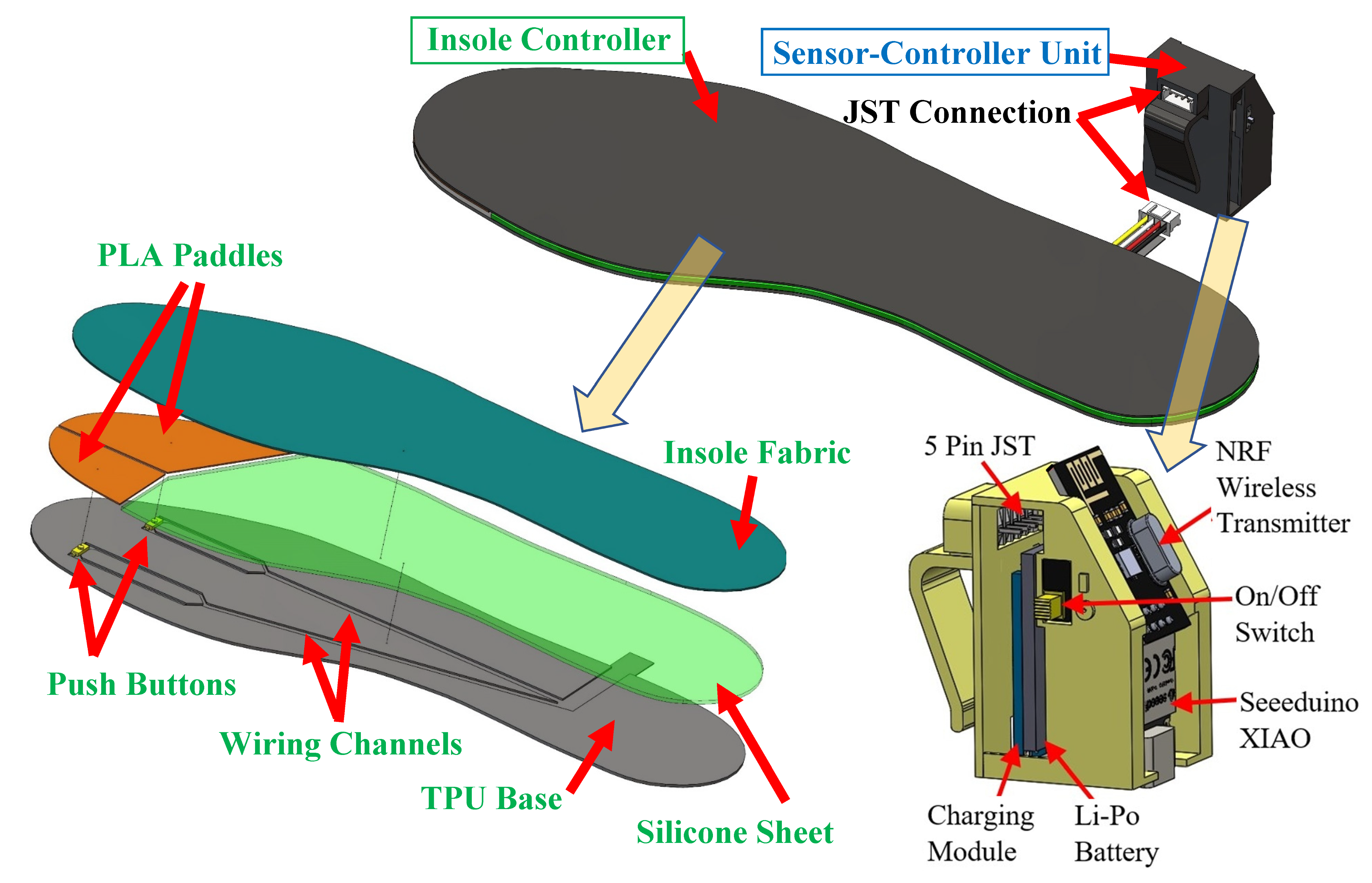
Figure 1. Infinity foot control system.
Prosthesis 05 00084 g001
Figure 2. Foot controller’s system architecture diagram.
Prosthesis 05 00084 g002
Figure 3. Overall architecture diagram for the foot controller and prosthetic arm.
Prosthesis 05 00084 g003
Figure 4. Illustration of finger grips/gestures corresponding to toe clicks. The light blue and red colors represent single clicks with the big toe and the four lesser toes, respectively. The dark colors represent long clicks, and “×2” symbol means repeat two times.
Prosthesis 05 00084 g004
Figure 5. Full CAD assembly of Infinity arm.
Prosthesis 05 00084 g005
Figure 6. Infinity’s wrist actuation mechanism.
Prosthesis 05 00084 g006
Figure 7. Exploded (a) and assembled (b) views of Infinity hand design.
Prosthesis 05 00084 g007
Figure 8. Infinity arm’s architecture diagram.
Prosthesis 05 00084 g008
Figure 9. Haptic feedback system: (a) fingertip force sensors and (b) sensory feedback armband.
Prosthesis 05 00084 g009
Figure 10. Architecture diagram for the sensing subsystem of the haptic feedback system.
Prosthesis 05 00084 g010
Figure 11. Architecture diagram for the sensory feedback subsystem of the haptic feedback system.
Prosthesis 05 00084 g011
Figure 12. Manufactured model of Infinity Arm.
Prosthesis 05 00084 g012
Figure 13. (a) Manufactured insole controller and SCU, (b) SCU clipped to a shoe.
Prosthesis 05 00084 g013
Figure 14. (a) Manufactured sensory feedback armband, (b) electronics box.
Prosthesis 05 00084 g014
Figure 15. Demonstration of the Infinity prosthetic arm connected to a mannequin’s upper arm with the sensory feedback armband.
Prosthesis 05 00084 g015
Figure 16. Sample time delay in wrist rotation data transmission.
Prosthesis 05 00084 g016
Figure 17. Simulation models for (a) push buttons, and (b) gyroscope.
Prosthesis 05 00084 g017
Figure 18. Foot controller testing mount with a servomotor and an attachment unit.
Prosthesis 05 00084 g018
Figure 19. Comparison between simulation and experimental wrist rotation data.
Prosthesis 05 00084 g019
Figure 20. Five grip patterns (relax, pinch, tripod, power, and point).
Prosthesis 05 00084 g020
Figure 21. Infinity arm grips different objects using different grip patterns.
Prosthesis 05 00084 g021
Figure 22. Foot dorsiflexion, plantarflexion, inversion, and eversion.
Prosthesis 05 00084 g022
Figure 23. Wrist bending and rotation.
Prosthesis 05 00084 g023
Figure 24. Foot controller training platform.
Prosthesis 05 00084 g024
Figure 25. Examples from the three phases of the foot control training procedure.
Prosthesis 05 00084 g025
Table 1. Example of foot control actions and prosthetic hand reactions.
Foot Control ActionResulting Prosthetic Hand Reaction
1Big toe single-clickRelax all fingers
2Big toe double-clickTripod
3Big toe long-clickPower
4Four-toe single-clickPoint
5Big toe then four-toe single-clicksPinch
6Foot dorsiflexionWrist extension
7Foot plantarflexionWrist flexion
8Foot inversionForearm supination
9Foot eversionForearm pronation
Disclaimer/Publisher’s Note: The statements, opinions and data contained in all publications are solely those of the individual author(s) and contributor(s) and not of MDPI and/or the editor(s). MDPI and/or the editor(s) disclaim responsibility for any injury to people or property resulting from any ideas, methods, instructions or products referred to in the content.