Article

Evolving 3D-Printing Strategies for Structural and Cosmetic Components in Upper Limb Prosthesis

1
Limbitless Solutions, University of Central Florida, 12703 Research Parkway, Suite 100, Orlando, FL 32826, USA
2
School of Visual Arts and Design, University of Central Florida, 12400 Aquarius Agora Dr, Orlando, FL 32816, USA
3
Department of Games and Interactive Media, University of Central Florida, 12405 Aquarius Agora Dr, Orlando, FL 32816, USA
4
Division of Trauma, Critical Care & Acute Care Surgery Department of Surgery, Oregon Health and Science University, Portland, OR 97239, USA
*
Author to whom correspondence should be addressed.
Prosthesis 2023, 5(1), 167-181; https://doi.org/10.3390/prosthesis5010013
Submission received: 18 November 2022 / Revised: 15 January 2023 / Accepted: 28 January 2023 / Published: 3 February 2023
(This article belongs to the Special Issue 3D Printing Strategies for Limb Prostheses)

Abstract

:
The evolution of prosthetic limbs continues to develop, with novel manufacturing techniques being evaluated, including additive manufacturing. Additive manufacturing (AM), or 3D-printing, holds promise for enabling personalized and tailored medical device options. The requirements for personalized medicine, coupled with the limitations of small-batch manufacturing, have made the technique viable for exploration. In this manuscript, an approach is presented for incorporating additive manufacturing for prostheses, both as a final part and in applications as an intermediate manufacturing step. As a result, through the use of these methods a multi-gesture capable electromyographic prosthesis was designed and manufactured, currently being evaluated in clinical trials for pediatric patients. This paper explored the results of this unique method of applying additive manufacturing techniques, and assessed how the blend of different manufacturing techniques improved performance and reduced device weight. Creating unique and aesthetic cosmetic coverings for the device was achieved through using additive manufacturing as an intermediate manufacturing component and, then, applying thermoforming. Cosmesis components saw a 33% reduction in weight from this change in manufacturing. The approach is explored to blend multiple manufacturing techniques to create cosmesis components and structural components for the prosthesis. The techniques serve the design intent to reduce reported challenges with upper limb prosthesis devices and to encourage device retention. Recommendations for manufacturing strategies are discussed, including the limitations.

1. Introduction

An ongoing challenge many prosthesis designers face is minimizing the rate of prosthesis rejection and non-use, which has been estimated to be between, approximately, 20 to 40 percent in the last few decades, among those with an upper-limb deficiency [1,2]. In many cases, overall device weight and limited functionality are stated to be some of the primary reasons for rejection [1,3,4]. Prosthetic limb devices also hold social and psychological significance that can affect the user’s self-confidence and well-being in social situations [5,6]. A misalignment between what the designer believes the user wants the device to visually express, versus the user’s actual preferences, can lead to the user becoming dissatisfied with their device, causing low adjustment to the prosthesis [7,8]. This paper explores the novel application of additive manufacturing techniques for the development of prosthetic limbs, with particular emphasis on benefits provided in functionality, weight reduction, and durability of the device.
This manuscript explores the manufacturing of a new research prosthesis device and a novel combination of manufacturing techniques that employ additive manufacturing to improve production and reduce overall prosthesis weight. A background section, on the state of the authors’ research, is provided. Methodology and resulting outcomes are discussed along with recommendations for the field in regard to ways by which additive manufacturing can be implemented in prosthesis design.

1.1. Prosthesis Classifications

The design for prosthesis has often times reflected a replacement mindset over one focused on expression [9]. Passive, or non-functioning prostheses, have largely been designed to approximate human skin tone and features. This may be in an effort to have the user’s reflection or reception in society be undifferentiated from a person without a limb difference [7,8]. Two classifications of functional prosthesis, namely body-powered and myoelectric devices, are often discussed as potential tools for those with limb differences. Each type of these devices, and the many variations, has perceived strengths and weaknesses. Body-powered devices rely on the user’s physical movements to open and close the prosthetic device. This is often achieved by a cable and harness system, which the user can move in specific directions to manipulate the prosthesis [10]. The harness is often reported by the user as being constraining and uncomfortable to use, and repeated movements to move the limb of the device may lead to fatigue and injury over time [10,11,12,13]. Those who prefer body-powered devices share that the devices are quieter, more reliable for manual work, easier to clean and maintain, require a relatively short training period, and are more intuitive through described proprioceptive feedback [10,13].
Children are reported to favor myoelectric devices over body-powered versions [14]. There may be a lack between the user’s intended action and what the prosthesis can actually achieve, due to the physical and sensory disconnect between the user’s residual limb and the device. Since the biomechanical actions involved in controlling a body-powered device are not necessarily in line with the action the user would perform to control the limb, different methods of powering and controlling the device started being developed. Early models that used compressed gas to power the device have now evolved into using bio-electric techniques to activate the electric movement of the device, notably through electromyography (EMG) and electroencephalography [15,16,17].
Non-invasive myoelectric devices rely on surface electrode stickers placed on the user’s residual limb muscles to detect electromyographic readings, through which the user can actuate the device by choosing when and how hard to contract the respective muscles [10,11,18,19]. Often the bicep muscles are targeted for upper limb amputees. Within myoelectric devices, there are several variations in how the surface EMG readings are processed to manipulate the device, such as on-and-off, proportional, direct, and pattern-recognition control [17]. These mechanisms typically require less effort from the user to create and sustain grip force compared to body-powered devices, and the lack of a harness may improve their cosmetic appeal and comfort, relative to body-powered devices [13,20].

1.2. Reported Limitations

For children with limb differences, the aesthetics of prosthetic devices holds greater importance, since the lack of cosmetic appeal is a largely cited reason for the high abandonment rate for those in their early teenage years [21]. Body-powered prostheses are often designed and manufactured in this same manner. These functional and visual design decisions have led some users to dismiss the devices, commenting that the unattractive nature of the device may not be worth the effort required to use the device [22]. The uncanny valley [23], or uncanny cliff [24], is a phenomenon discovered and widely discussed in both scientific literature and popular culture. This phenomenon describes the elicitation of negative feelings, instead of attraction, when a person views an artificial human approximation, especially noticeable in the field of robotics along with computer-generated characters [25]. This effect is complex, with a variety of factors driving the human response, and leads to the dynamic nature of anthropomorphism [25,26].
The mean rejection rate for body-powered devices is reported to be 26%, whereas the mean rejection rate for myoelectric devices is lower at 23% [1,11]. Comfort and device weight are both commonly reported rationales for reduced prosthesis usage or abandonment, with myoelectric devices having increased weight for increased functionality [1,27]. Some reported drawbacks of myoelectric devices include the fact that they require batteries to be re-charged or replaced, and are perceived to be noisier and heavier [13,14]. Myoelectric devices can also involve longer training periods, due to a lack of proprioceptive feedback, and require the user to learn how to control muscles they may not have used before [13] to actuate the bionic functions. This can make performing even simple tasks tedious and frustrating [3]. The device may also suffer from poor body heat dissipation in the human–machine integration socket, making it too uncomfortable to use [1]. This may be especially exasperated in high-temperature climates.
An emphasis on the aesthetics of myoelectric devices in recent years may offer insights into why myoelectric devices are requested more among children and have a lower mean rejection rate. The functional design methodology has evolved to additionally consider the visual design, as a symbol and form of expression for users, beyond the focus on mechanical grasping and human form replication [4,7,8]. This has shifted the designer’s priorities from creating something that closely resembles the missing limb, matching skin tones and a human-like appearance to help the device ’blend in’, to understanding what each user’s visual expression preferences are to maximize psychosocial comfort and confidence. This has increasingly involved non-human form visual designs and a wider range of expressive shapes and non-human skin tones [7,8]. Additionally, new visual designs have emerged that blend fashion and prosthesis [25,28] or animal aesthetic influences [29].
Low adjustment to limb loss and devices correlates with increased social isolation, whether this is due to the user being displeased with their device’s functional and visual design or any negative attention the device may draw from their community [5]. For children, this can take the form of being teased at school for their prosthesis, making this critical stage of social development more difficult [12]. Social isolation can, in turn, create doubts regarding self-image and body confidence, potentially making the individual with limb loss feel as though they lack control over their disability in social interactions, and, in some cases, leading to elevated rates of depression [6].

1.3. Manufacturing Techniques

Manufacturing of prostheses has evolved, using a combination of traditional manufacturing techniques. These techniques can be subdivided into three classes including forming, subtractive machining, and additive manufacturing [30]. Designing for a particular manufacturing technique requires considering topology optimization as playing an important role in achieving mechanical properties or the performance needed for the application [31,32].
Leveraging additive manufacturing enables high-complexity 3D designs to be manufactured, in particular for low production volume, at relatively inexpensive costs [33]. Additive manufacturing has been of interest in the field of prosthesis design due to several positive attributions, including the opportunity to use it for rapid prototyping. Additionally, the method can reduce iterative design costs and reduce the weight by manufacturing parts with set in-fill percentages (which may include honeycomb-like patterns, among others [34,35]). The relatively high material and cost efficiencies of 3D-printing allow for rapid prototyping of products [33,36,37]. Enabling a machine to run production has secondarily reduced labor-intensive tasks, which often require uniquely skilled technical abilities [38]. Additive manufacturing can be performed through a variety of techniques, including material extrusion, powder bed fusion, and photopolymerization [39]. The digital framework for mechanical designers to digitally create and manufacture base models, which can then be further tailored to the individual patient, has accelerated a global effort to collaborate on prosthesis design [18]. As online communities, focused on 3D printing, and cloud based 3D modeling software have developed, participation from a wide variety of makers, engineers, and artists has made the holistic design process multidisciplinary [19,33,37].
Printed parts may require additional supports, including rafts and overhangs, to support structural integrity during manufacturing. There are several types of post-processing that may be required. Some printers implement a soluble support material that must be dissolved. Others may use breakaway support material that can be removed manually or by sandblasting.
The post-processing for fused deposition modeling (FDM) parts can require significant time to produce a quality surface finish, sufficient for an end-user product. The removal of material, through sanding or dissolving, may influence mechanical properties or final geometries and can affect, overall, the assembly and the part. Photopolymerization printers, often using a light-sensitive resin liquid, have a high curing spatial resolution, resulting in reduced surface roughness. Post-processing may include a wash and curing station, to remove excess resin and complete the curing process. The degree to which the part is cured influences the mechanical properties of the component, while the part remains susceptible to naturally occurring light.

1.4. Aesthetic Design Considerations

In choosing mobility devices for their child, parents have also been shown to prioritize visual appeal over initial proficiency with the device [40]. Involving the user in the visual design process, by providing the designer and user with an opportunity to have a conversation, or directly allowing the user to customize the visual design, may lead to an increased emotional connection between the user and their device, which may further help prevent rejection [7,19]. To satisfy the need for user-focused devices, each device may need tailoring to the specifications of the user, which limits the scale and rate of prosthesis production, due to the potentially high variability [7].
Aesthetics and fashion allow people to communicate and connect emotionally, and prostheses with an artistic form can express character, personality, and values, allowing others to see the users as they wish to be viewed [8,19]. The concepts of design and art are often contrasted, with design being seen as a means to an end (form following function) and art as a means of self-expression (function following form). Functional requirements often dictate design decisions and prostheses have often adapted to have a structural framework and an attaching cosmesis.
Electromyographic prostheses have had their design evolve largely around metallic parts, carbon fiber reinforcement for weight reduction, and uncharacteristically in-organic forms. This type of design may lead to increased perceptions of affinity for the device, re-categorizing the object as more similar to a piece of electronic technology than a piece of human form acting as a replacement part [7].

2. Background

2.1. Device Development

In response to reported challenges in having access to prosthetic limbs for children born with congenital limb differences, a novel device was developed in an effort to provide a prosthesis without financial burden. The hardware developed for the investigation heavily leveraged additive manufacturing for the various plastic components, comprising the circuitry and mechanical components for the electromyographically-actuated functionality of the device. In the development phase, a priority was placed on minimal device weight, a battery life that could accommodate at minimum a full 8-h use pattern, sufficient grip and strength appropriate for a child in the range of 8–12 years of age, and unique aesthetic components to encourage device affinity for the user.
The research device developed includes five brushed DC motors, each weighing 10 grams including circuitry ribbon cable. The motors draw 1.6A and have an applicable 210:1 gearing ratio. The motors are located at the base of each finger, enabling each finger to be actuated individually or in programmed routines. Processing circuity, motor drivers, and EMG acquisition system are located on a printed circuit board in the palm of the hand. The battery pack selected is of Li(Ni,Co,Al)O2 (NCR) composition, with 7.4 V nominal charge and 3200 mAh, and weighs 101 g. The size of the battery is 68 × 37 × 27 mm and is housed with additional circuitry in the battery core component located in the “forearm” of the device. Each structural piece is modular and can be connected, including the hand, forearm battery core, and socket. Charging of the device uses a USB type C charger connected to the hand component. The aesthetic components, cosmesis assembly, magnetize to the structural components and can be interchanged.

2.2. Clinical Investigation

In the authors’ research, the novel bionic limb was developed and deployed for evaluation under a clinical trial based at the University of Central Florida and Oregon Health and Science University [19]. The investigation was registered under ClinicalTrials.gov (accessed on 7 November 2022) Identifier: NCT04059107. Throughout the course of the multi-year investigation, manufacturing techniques evolved to support robustness, weight reduction, and aesthetics. The lessons learned influenced the applied techniques to integrate a variety of manufacturing methods.

2.3. Aesthetic Design

For the prosthetic device tested in this clinical trial, the cosmesis began as a magnetized 3D-printed shell that could be interchanged readily in a one-handed task. Bar style magnets were employed to allow for intrinsic alignment of the components, with polarities compatible with matching sub-components. This also provided immediate feedback for cosmesis sub-component appropriate locations, to ensure the correct assembly by the user. A web-based customization portal was developed, which enabled participants to explore different cosmesis choices and their 3D geometries. This enabled the user to select their preference in different topography styles, and the visual design features’ colors [19]. The customized cosmesis comprised three pieces, two covering the structural forearm components and one covering the top face of the hand. After the manufacturing process, the structural and cosmetic components proceeded to an automotive paint finish, which further reduced the surface roughness and unwanted defects. This coating also reduced the effects of ultraviolet light exposure and could add a spectrum of color to the part. Createx Colors automotive paint, a fluid acrylic resin paint, was used throughout.
Holistic design decisions were prioritized to include the end user’s aesthetic needs and desires into the visuals of the prosthesis. The user’s participation in the aesthetic design, shaping the artistic outcome, was anticipated to result in increased affinity to the device. Increased device affinity was valued in an effort to reduce prosthesis rejection rates.

3. Methods for Implementing Additive Manufacturing

3.1. Direct Part Manufacturing

All final components produced by additive manufacturing were printed on a Stratasys Fortus 250 fused deposition modeling (FDM) machine, in the common thermoplastic polymer acrylonitrile butadiene styrene (ABS) with soluble support material as needed. ABS plastic, relative to polylactide or polylactic acid thermoplastic (PLA), has more dimensional stability tolerance in higher temperature climates. For a prosthesis, this difference is often identified if the device is left in a hot car.
In application, the printing orientation and the thickness of the additive manufactured parts play a significant role in their longevity. This type of manufacturing is significantly anisotropic in nature and is strongest with the force perpendicular to the stacked layer lines. This requires optimization in the structural design phase and the manufacturing phase, with the strongest anticipated loading forces considered for orientation selection. Sub-components are printed in batches, filling an entire tray with one component and consistent printing orientations.
In this device, many components were modified to include metal fixtures for additional robustness and for integration with fasteners, and particular attention had to be given to optimizing the anticipated loading around such stress concentrators.

3.2. Thermoforming via Additive Manufacturing Positive Die

Thermoforming is a process that takes a sheet of plastic and applies temperature to reach the glass transition point, then applies a negative pressure to suction the sheet of plastic around a positive die mould (sometimes called a ‘buck’ or ‘plug’). Thermoforming has been implemented by a variety of companies for prosthesis’ sockets, for both prosthetic legs and arms. A positive mold of a patient’s amputated limb geometry made from plaster or machined foam is created, often by hand, and prepared for thermoforming [38,41,42]. Other literature has explored 3D-printed bucks that were tested and produced favorable results when tested for use in thermoforming for prosthesis [42]. Three-dimensional printing, and FDM methods, specifically, have been shown to be a potential replacement for more conventional materials in buck creation process [43,44].
During the development of the prosthesis device, manufacturing methods were considered to reduce the extensive post-processing time to sand down surface striations and defects, required to achieve the desired surface finish before the adhesion paint primer was sprayed. For the cosmesis components, optimizing processing time and durability were both concerns. Thermoforming was selected as an alternative manufacturing method for producing the cosmesis components, enabling components to be manufactured with greater speed and to improve mechanical properties, including flexibility, as compared to the FDM-manufactured versions.
For this application, an ABS sheet of plastic, measuring 1.4 mm in thickness, was applied using a Formech Newform 16:16 machine. The original 3D model for the cosmetic sleeve required digital manipulation to convert the features into a positive mold. These forms were functionally designed to have exaggerated surface features, as the thickness of the plastic in the thermoforming process would reduce the appearance of the visual design elements. The positive mold was then prepared for FDM-manufacturing, with lower infill. The base of the grown part was modified with a drill to allow the vacuum table to pull suction throughout the honeycomb infill of the mold. For more sensitive features, a small hole could be added to the mold surface to increase the effectiveness of the production.
The method also reduced the striations remaining from the 3D-printing method, which greatly reduced post-processing requirements. An example of 3D-printing for a positive mold is presented in Figure 1 (Left side). A completed manufacturing process can be seen in Figure 1 (Right side). If geometrically feasible, all three cosmetic parts of a set would be thermoformed at once.

3.3. Overmolding via Additive Manufacturing Moulds

Prosthesis grip strength and distribution is an important consideration, with reports of commercially available prosthesis actuating with 10.8N to 29.5N [45]. Finger approximations, manufactured from 3D-printed plastic, may struggle in contact with objects due to insufficient friction at the point of contact. To increase the functionality of the prosthesis, liquid silicone rubber (LSR) molding was selected to be added to the gripping portion of the device using overmolding. Overmolding manufacturing produces a two-piece assembly, often with dissimilar materials, where the second component is molded over the original piece [46]. This can be achieved by creating an additive manufactured component and an additive manufactured negative molding chamber that encompasses the original part and additional volume to be molded.
One technique for applying this method for prosthesis manufacturing includes a casting mixture of a multipart silicone elastomer which is then injected into the chamber encompassing the primary part. DragonSkin series silicone elastomer, a platinum cure that leverages cross-linking, was selected for this application to produce an improved grip on the fingertips.

3.4. Injection Molding Prototyping via Additive Manufacturing

Injection molding, a traditional manufacturing method, operates by injecting molten material into a molding chamber. This method is effective for large scale economical production volume, but tends to have an expensive initial cost for mold development, machining, and validation. The mechanical design considerations for manufacturing a component via injection molding vary from those for additive manufacturing. In an effort to develop and validate more time efficient component designs for injection molding, additive manufacturing has enabled rapid prototyping of the design modifications to enable the components to be effectively molded. Evaluation of fit checks and compatibility, can greatly accelerate the manufacturing process.
Injection molding prototyping was conducted using a Morgan-press vertical injection molding machine, injecting ABS plastic with 20 tons of clamping force with a 0.25 inch nozzle. Aluminum molds were subtractively manufactured using a Tormach 3 axis CNC mill 1.5 hp motor and 10,000 rpm spindle speed maximum.

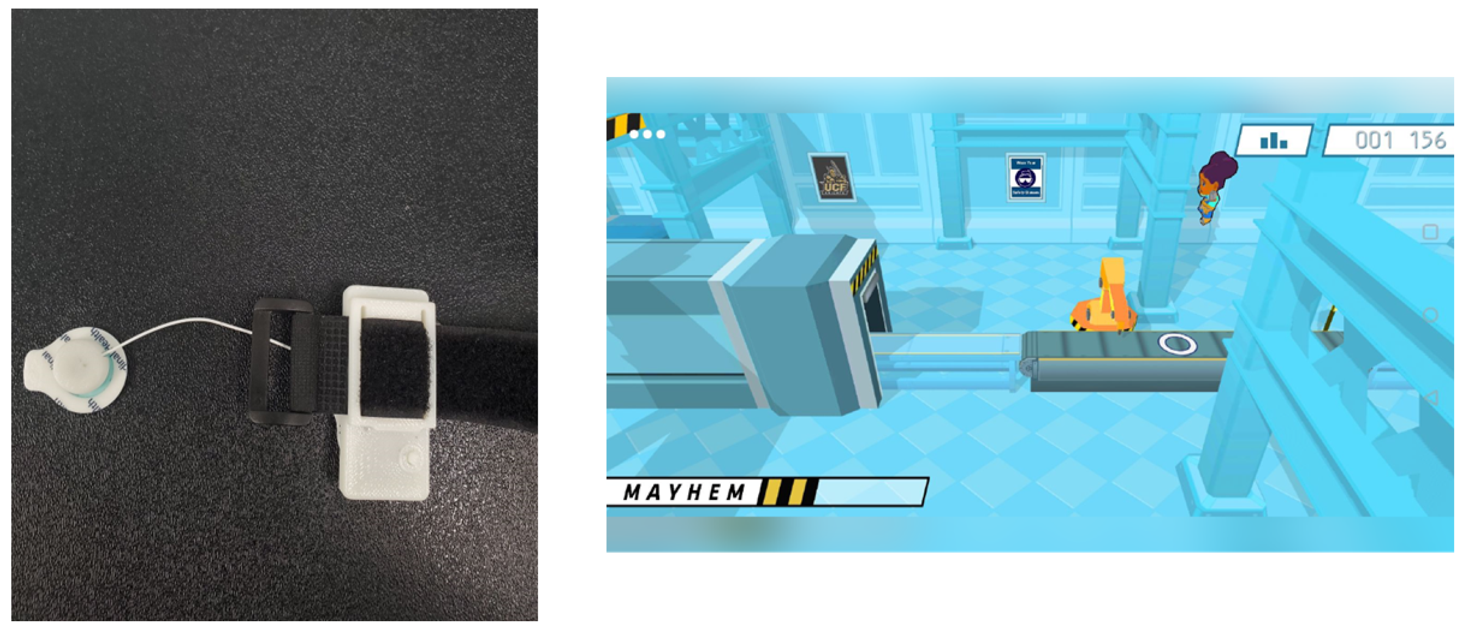
3.5. Accessories and Additional Components

In the prosthesis system described, there is a training component that uses an Android software tablet and a Bluetooth-connected in-house manufactured EMG game controller, which contains the same input circuitry hardware as that found in the hand assembly. This interface combines the use of video games to make the training exciting and to create a safe environment in which to fail and to learn to operate the prosthesis, but the controller itself must also complement this environment and support the user’s interest in continued training.
The game controller is manufactured as part of the overall prosthesis system. However, unlike many of the other components, it does not require adjustment or additional manufacturing with the user’s growth over time. The initial manufacturing is conducted in relatively small numbers to support the clinical trial population. The game controller is classified as an accessory to the prosthesis system.
The game controller is often the first component that the user interacts with, as training is often used to establish baseline control for the EMG prosthesis interface and calibration. It is used in training the user to adapt to the prosthesis and to strengthen the muscles on the amputated limb, which have often not been exercised before by the user. This training system leverages training video games that guide users from route flexing at any strength, to the ability to flex in a more finessed way, at variable strengths. As the user levels up in the training games, they also level up in their prosthesis to include the ability to do multi-gestural controls. This is done in a gamified platform to provide a safe, low stress, and enjoyable way for the user to learn what is required [47].

4. Results

The application of these methods for implementing different additive manufacturing strategies was conducted to improve the performance of the novel device. This resulted in changes to the cosmetic and structural components of the device.

4.1. Direct Part Manufacturing Outcomes for Implementing Aesthetic Design

Each patient selected two sets of cosmetics and had the opportunity, with their parents or guardian, to participate in the visual design phase. The customization web portal can be seen in Figure 2, where participants could select from different 3D designs and pre-set color palettes. Further refinement of the visual design features’ color selections could be made with the color wheel and selector, allowing for full customization.
Upon finalizing the selection, the cosmetic components were then 3D-printed and prepared for the painting process. The post-processing was extensive, with different 3D geometries requiring different levels of preparation and painting. The conversion to thermoformed parts, via additive manufactured positive molds, resulted in significant manufacturing and post-processing time saving, along with improved surface finish. The final visual result produced a level of anthropomorphism but pushed the aesthetic design to be more similar to a fashion piece or an armored gauntlet. The expression of color and form was intentionally non-human in skin tone and more akin to body-art self-expression than an analog to the patient’s other limb, which was believed to be an important connection point for the user wearing the device. A presentation of different finished cosmesis can be seen in Figure 3. These efforts were intended to further reduce the rejection rates for advanced prostheses, as well as to improve daily functionality and reported device affinity.
The aesthetic finish of the cosmesis was applied through the use of airbrushing automotive-grade paint. Optimizing durability was a major priority within the painting process. The use of automotive paints and durable clear coats ensured a longer-lasting result, with minimal retouching necessary afterward. A primer was applied to further enhance adhesion with the plastic surface, after the surface roughness quality had been optimized. Adhesion might be insufficient if the surface roughness was too significant or overly polished.

4.2. Thermoforming Outcomes for Reduced Manufacturing Time, and Increased Durability

After completing the conversion of the 3D model from an additive manufactured part to an additive manufactured positive mold, the cosmesis components were produced using thermoforming. A completed assembly, post-cosmetic painting, is presented in Figure 4. The honeycomb nature of 3D-printed plastic could be advantageous to achieve a high-quality finish, due to the suction profile across the volume. The thermoforming process significantly reduced the time to manufacture multiples of a component. The thin sheet of ABS plastic performed more resiliently than the 3D-printed counterpart, and the weight of the part was reduced. Limitations did remain, including minimum feature sizes that could translate through the forming material and the geometries that could be manufactured. Geometries with manufacturing limitations included self-contained volumes or shapes with severe undercuts, though additional post-process trimming and layering could accommodate for these features.

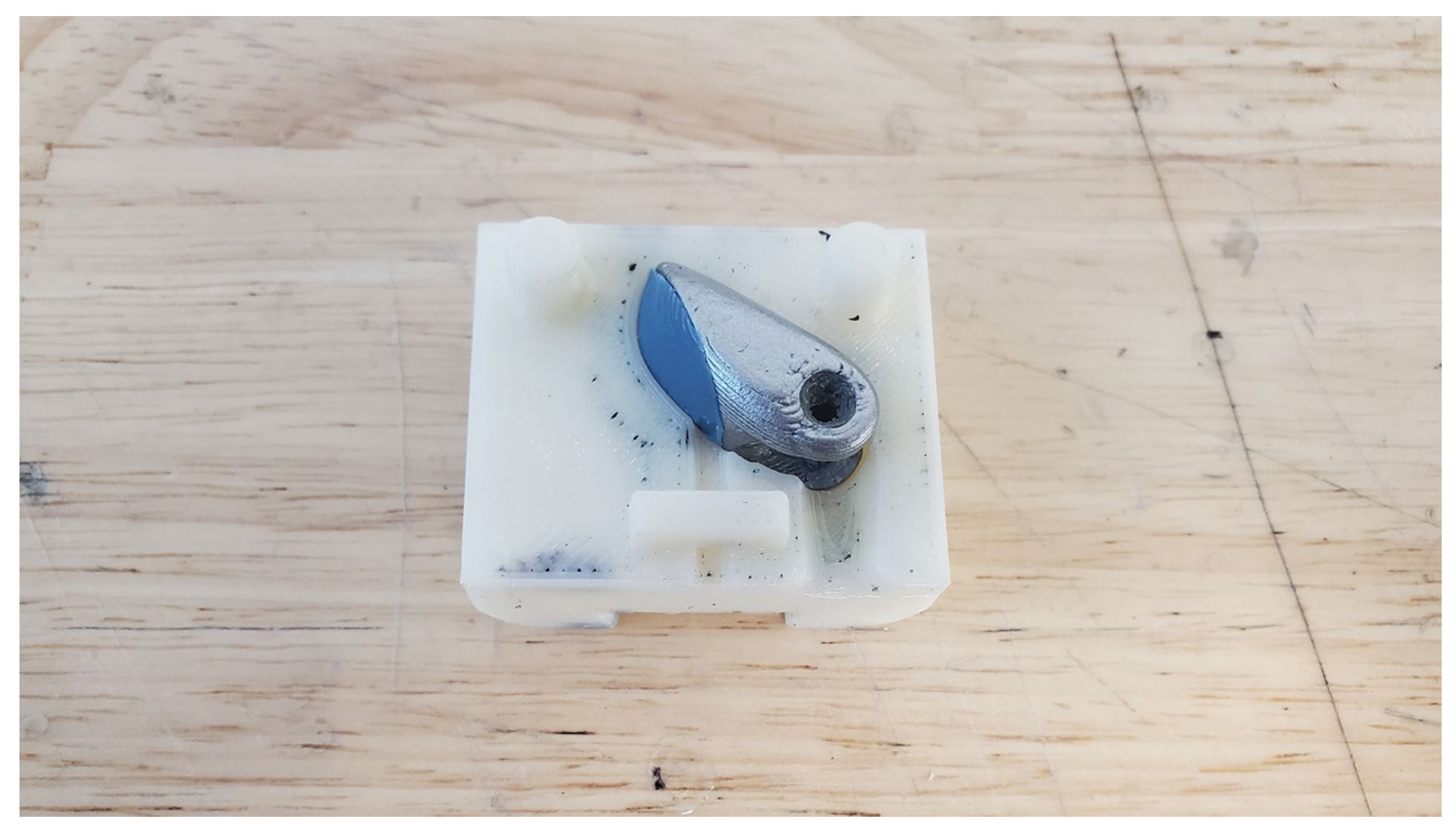
4.3. Overmolding Outcomes for Improved Grip

The fingertip components were designed with a negative cavity that could be overmolded with the addition of an LSR compound, to enable adherence and grip performance. This additionally increased surface area and localized friction at the point of contact while grasping objects, with ABS having a low coefficient of friction and the LSR compound, had a more similar frictional coefficient to human skin. The parameters of the part and its accompanying molding chamber could be adjusted concurrently, leading to more rapid prototyping speeds. A final set of printed molds was produced, enabling multiple fingertips to be completed in one production run. An example finished component is presented in Figure 5.

4.4. Manufacturing Accessories

The controller was a wireless device, as was the prosthesis, and needed to be connected to the calibration app or the training games. The controller was kept small and light to be able to be used for long periods of time by children or people without much arm strength. The controller included a battery, which was the heaviest single component in the device. The battery was kept small enough to reduce weight, and improve charging times, but was powerful enough to allow for 30 min of continuous training. The controller was light enough to affix to the user with only the contact surface EMG electrode stickers that were used for input. However, users were often concerned that the controller would disconnect during use. To accommodate this concern, the controller had attachments for an adjustable strap. This Velcro fastened strap did not add much weight to the system and helped keep the controller in good contact with the skin. The battery could be replaced with a larger version for adults, but the width relative to the user’s arm width, and weight-to-mAh ratio, were critical considerations to allow for the most success for new users.
During development, this custom device had requirements to safely contain the electronic components, interface with the human, and appear visually congruent with the prosthesis system. The controller, and the tablet-based software that it interacted with had to be exciting to the user, as the training they were being asked to do was often hard, and less than fun. Minimizing weight was critical. The materials used for the prototype controller were the same materials, namely, 3D-printed ABS plastic, found in the rest of the prosthesis. This manufacturing method was excellent for the small volume of customized parts necessary and mechanical requirements. The 3D-printed material was printed thin enough that the lights on the boards were visible through the plastic to provide visual indicators, using colors and patterns to represent powered on Bluetooth connectivity states. A small 3D-printed button allowed the component to be turned on or off. The controller housing and an image from the training game can be seen in Figure 6.

4.5. Overall Weight Reduction from All Methods

Pediatric patients have reported that even low-weight prostheses being worn for several hours can be energy-draining. Those feelings can decrease the usefulness of the device and reduce overall usage, leading to outright rejection if the device is not adding sufficient value. The novel device reported here continues to evolve as new manufacturing methods are integrated into production. The current capabilities include multi-gesture hand states, including a gross grasp, pinch, and point. Table 1 reports the current manufacturing weights and reduction comparisons, with the base prosthesis hand from fingertip to wrist base, reported at 200 g. This compared favorably to other commercial and research hands’ weights [45]. The closing speed of the hand was approximately 1.5 s for gross grasping and pinch gestures, without obstructions.
Implementing the conversion to a thermoformed cosmesis resulted in a reduction of 33% of the cosmesis weight, for a savings of 39 g. This weight reduction might be even more valuable over a full day of prosthesis use, helping to reduce fatigue. A comparison is also presented in Table 1 for the conversion of the additive manufactured battery core against a new ABS plastic injection molded battery core. This weight, comprising the battery, circuitry, and paint showed a modest 5% reduction in component weight. While similar in weight, the conversion resulted in more significant robustness than the additive manufactured counterpart.
These results also demonstrated where different components might benefit from examining the manufacturing techniques and ease of prototyping. Robustness with ABS additive manufacturing, particularly with repeated cycling, could be limited. This resulted in bulkier printed parts, where thickness ccould be reduced for a higher-density version of the same material. Overall, this study leveraged ABS plastic through additive manufacturing, thermoforming, and injection molding, while assemblies also incorporated metallic components and LSR polymers.

5. Conclusions and Recommendations

With additive manufacturing machines’ accessibility, there is now an opportunity to re-examine manufacturing methods for prosthesis devices and their cosmesis, and to be able to evolve the devices to include visual design co-participation by the user. The developed prosthesis, currently being evaluated in research trials, has integrated a variety of additive manufacturing methods, resulting in weight reduction, increased robustness, and increased efficiency in production. The additive manufacturing methods enabled cosmesis components to include visual design elements. There remains significant work to be done to bring these methods beyond research devices and into the standard of care devices.
For implementing additive manufacturing for prosthesis, the level of complexity, mass manufacturing volume anticipated, and the anticipated mechanical loading must be examined on a component-by-component level. Recommendations for additive manufacturing strategies based on recent clinical evaluations include the following:
  • Prostheses are a regulated device in many countries, and clinical research often requires medical institution involvement. Patient feedback is critical to continuing the improvement of the device. Novel manufacturing methods may result in different regulatory considerations, and researchers should work closely with their institution’s compliance teams.
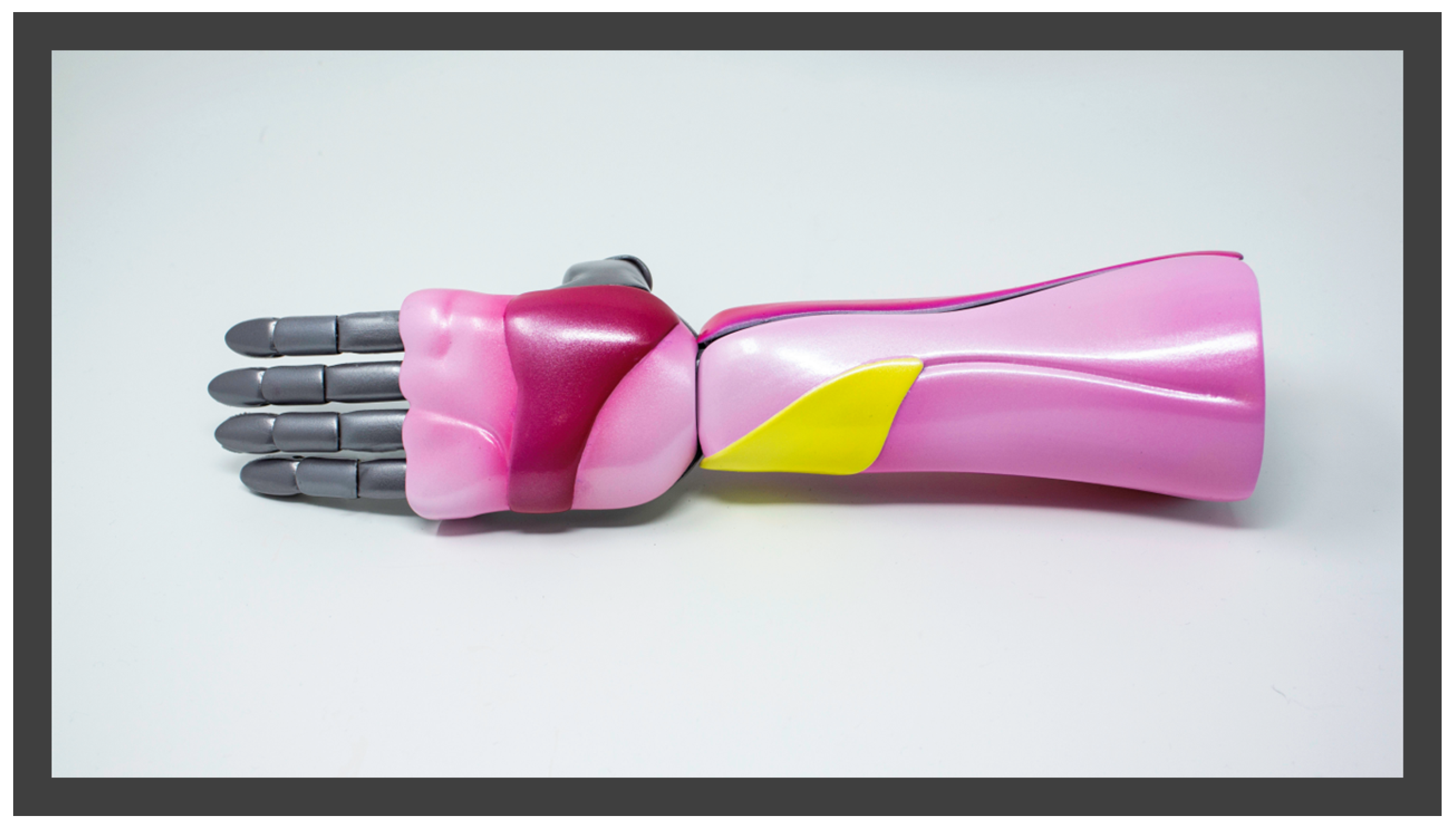
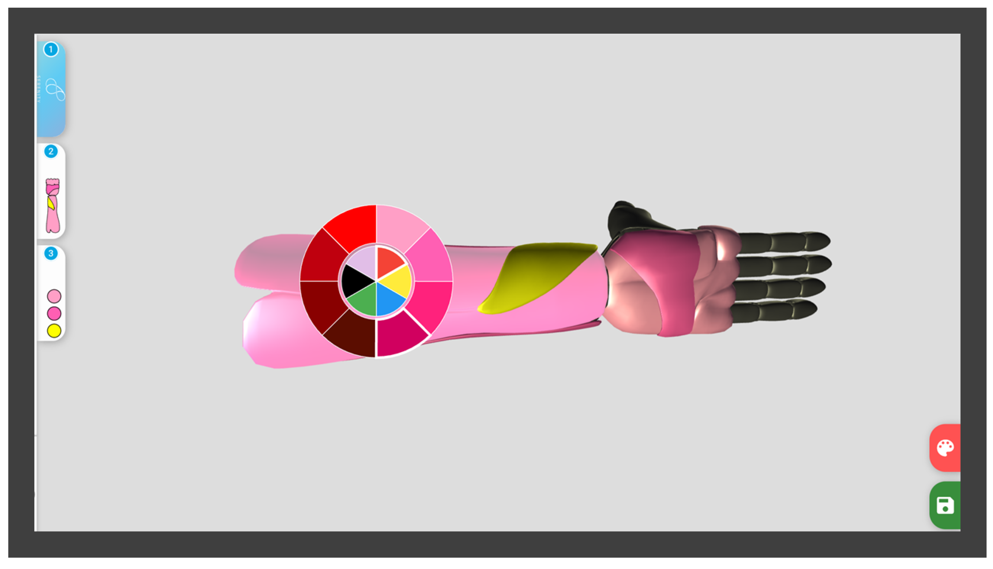
  • The customization opportunities when using an additive manufacturing approach enable extensive aesthetic expression. Incorporating the device’s user in the aesthetic choices, referred to as a variation of participatory visual design labeled ’cooperative expression’ [19], may provide increased affinity to the device.
  • Additive manufacturing is an effective tool for prototyping, and in certain use cases, but components must be mechanically designed to use traditional fasteners and to integrate into multi-part assemblies. These fasteners may include binding posts, screws, anchors, and hinges. The integration points between additive parts and traditionally manufactured components may lead to stress concentrations, and optimization for printing orientation, parameters, and applied loading conditions must be taken into account with additional caution.
  • Parts manufactured by additive manufacturing may be susceptible to cyclical loading failure or part degradation over time [48], making points of integration, for example, for mechanical joints, of high priority for additional robustness.
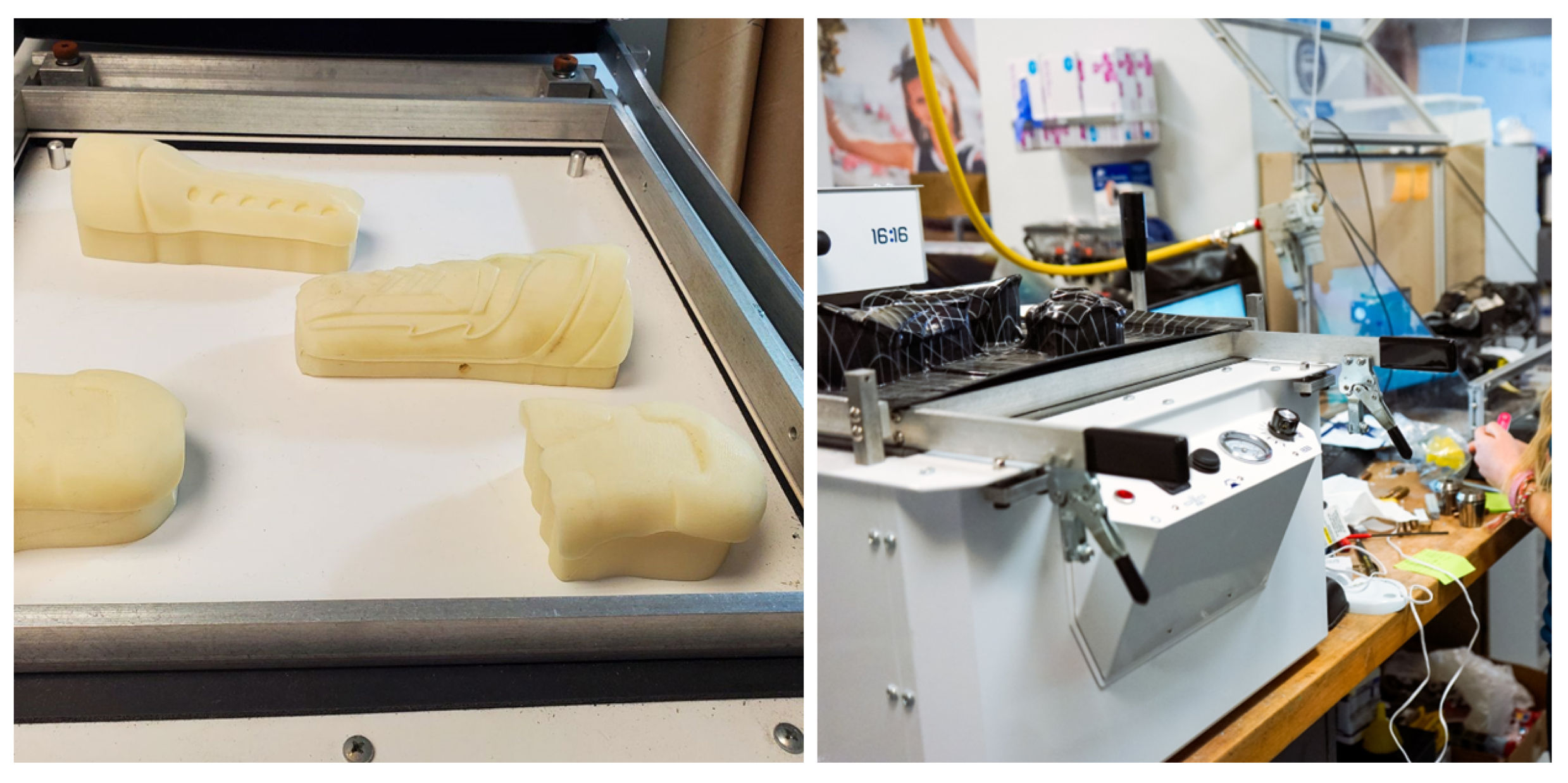
  • Additive manufacturing for the creation of positive molding, to be used with thermoforming, can allow for increased manufacturing production rates and increased part robustness. FDM-produced positive molds for thermoforming applications may be limited to 50 production pulls before cosmetic detail could be lost. The improvement in surface finish and flexibility provides excellent properties for final cosmetic parts that require aesthetic treatments.
  • Cosmetic components for prosthesis are a segment of prosthesis limb manufacturing that is primed for involvement from additive manufacturing. The resulting devices may hold promise to reduce overall cost and device weight, while also being capable of producing complex visual features that would not be cost effectively manufacturable in low production volumes through other methods.

Author Contributions

Conceptualization, A.M., J.S., M.D., P.S. (Peter Smith) and A.C.; A.M. and J.S.; hardware, J.S.; writing—original draft preparation, A.M., P.S. (Peter Smith), M.D, P.S. (Pavan Senthil), S.S. and V.R.; writing—review and editing, all; All authors have read and agreed to the published version of the manuscript.

Funding

This research received no external funding.

Institutional Review Board Statement

The study was conducted in accordance with the Declaration of Helsinki, and approved by the Institutional Review Board (or Ethics Committee) of Oregon Health and Science University, protocol STUDY00017087 first approved 2-15-2019 and the University of Central Florida under SITE00000017 first approved 4-3-2019.

Informed Consent Statement

Informed consent was obtained from all subjects involved in the study.

Data Availability Statement

Not applicable.

Acknowledgments

The authors would like to thank the clinical staff, patients, and caregivers who provided their time and feedback for participating in the overarching research trial. They also extend appreciation to Dominique Courbin, the interdisciplinary student research team at Limbitless Solutions, and our alumni. Limbitless Solutions also acknowledges the Createx Colors for their in-kind support of automotive airbrush paints and training.

Conflicts of Interest

The Limbitless Solutions organization has received financial and in-kind support from the 3D printer manufacturer Stratasys and 3D design software manufacturer Autodesk. Limbitless Solutions has also received in-kind products from CreatexColors. While data from the research study are not presented herein, the authors want to disclose that the funders had no role in the design of the overarching research study; in the collection, analyses, or interpretation of data; in the writing of the manuscript; or in the decision to publish the results.

Abbreviations

The following abbreviations are used in this manuscript:
AMAdditive Manufacturing
ABSAcrylonitrile Butadiene Styrene
CADComputer-aided Design
EMGElectromyography
LSRLiquid Silicone Rubber
PLAPolylactic Acid

References

  1. Biddiss, E.A.; Chau, T.T. Upper limb prosthesis use and abandonment: A survey of the last 25 years. Prosthetics Orthot. Int. 2007, 31, 236–257. [Google Scholar] [CrossRef]
  2. Salminger, S.; Stino, H.; Pichler, L.H.; Gstoettner, C.; Sturma, A.; Mayer, J.A.; Szivak, M.; Aszmann, O.C. Current rates of prosthetic usage in upper-limb amputees—Have innovations had an impact on device acceptance? Disabil. Rehabil. 2020, 44, 3708–3713. [Google Scholar] [CrossRef]
  3. Østlie, K.; Lesjø, I.M.; Franklin, R.J.; Garfelt, B.; Skjeldal, O.H.; Magnus, P. Prosthesis rejection in acquired major upper-limb amputees: A population-based survey. Disabil. Rehabil. Assist. Technol. 2012, 7, 294–303. [Google Scholar] [CrossRef] [PubMed]
  4. LeBlanc, M.A. Innovation and improvement of body-powered arm prostheses: A first step. Clin. Prosthetics Orthot. 1985, 9, 13–16. [Google Scholar]
  5. Gallagher, P.; Maclachlan, M. Adjustment to an Artificial Limb: A Qualitative Perspective. J. Health Psychol. 2001, 6, 85–100. [Google Scholar] [CrossRef]
  6. Murray, C.D. The Social Meanings of Prosthesis Use. J. Health Psychol. 2005, 10, 425–441. [Google Scholar] [CrossRef]
  7. Blom, J. The aesthetics of prosthetic greaves: Co-design for expressing personal identity. Making Futures 2018, 5, 18. [Google Scholar]
  8. Sansoni, S.; Wodehouse, A.J.; Buis, A. The aesthetics of prosthetic design: From theory to practice. In DS 77: Proceedings of the DESIGN 2014 13th International Design Conference, Cavtat, Coratia, 19–22 May 2014; pp. 975–984. [Google Scholar]
  9. Hall, M.L.; Orzada, B.T. Expressive prostheses: Meaning and significance. Fash. Pract. 2013, 5, 9–32. [Google Scholar] [CrossRef]
  10. Nagaraja, V.H.; da Ponte Lopes, J.; Bergmann, J.H.M. Reimagining prosthetic control: A novel body-powered prosthetic system for simultaneous control and actuation. Prosthesis 2022, 4, 394–413. [Google Scholar] [CrossRef]
  11. Carey, S.; Lura, D.; Highsmith, M. Differences in myoelectric and body-powered upper-limb prostheses: Systematic literature review. J. Rehabil. Res. Dev. 2015, 52, 247–262. [Google Scholar] [CrossRef]
  12. Wagner, L.V.; Bagley, A.M.; James, M.A. Reasons for prosthetic rejection by children with unilateral congenital transverse forearm total deficiency. JPO J. Prosthetics Orthot. 2007, 19, 51–54. [Google Scholar] [CrossRef]
  13. Uellendahl, J. Myoelectric versus body-powered upper-limb prostheses: A clinical perspective. JPO J. Prosthetics Orthot. 2017, 29, P25. [Google Scholar] [CrossRef]
  14. Biddiss, E.; Chau, T. Upper-limb prosthetics: Critical factors in device abandonment. Am. J. Phys. Med. Rehabil. 2007, 86, 977–987. [Google Scholar] [CrossRef]
  15. Childress, D.S. Powered Limb Prostheses: Their clinical significance. IEEE Trans. Biomed. Eng. 1973, BME-20, 200–207. [Google Scholar] [CrossRef]
  16. Childress, D.S. Historical aspects of powered limb prostheses. Clin. Prosthetics Orthot. 1985, 9, 2–13. [Google Scholar]
  17. Geethanjali, P. Myoelectric control of Prosthetic Hands: State-of-the-art review. Med Devices Evid. Res. 2016, 9, 247–255. [Google Scholar] [CrossRef]
  18. Manero, A.; Sparkman, J.; Dombrowski, M.; Buyssens, R.; Smith, P. Developing and training multi-gestural prosthetic arms. In Proceedings of the Virtual, Augmented And Mixed Reality: Interaction, Navigation, Visualization, Embodiment, and Simulation: 10th International Conference, VAMR 2018, Held as Part of HCI International 2018, Las Vegas, NV, USA, 15–20 July 2018; 2018; pp. 427–437. [Google Scholar] [CrossRef]
  19. Manero, A.; Smith, P.; Sparkman, J.; Dombrowski, M.; Courbin, D.; Kester, A.; Womack, I.; Chi, A. Implementation of 3D Printing Technology in the Field of Prosthetics: Past, Present, and Future. Int. J. Environ. Res. Public Health 2019, 16, 1641. [Google Scholar] [CrossRef]
  20. Parker, P.; Englehart, K.; Hudgins, B. Myoelectric signal processing for control of powered limb prostheses. J. Electromyogr. Kinesiol. 2006, 16, 541–548. [Google Scholar] [CrossRef]
  21. Scotland, T.; Galway, H. A long-term review of children with congenital and acquired upper limb deficiency. J. Bone Jt. Surgery Br. Vol. 1983, 65, 346–349. [Google Scholar] [CrossRef]
  22. Murray, C.D. Being like everybody else: The personal meanings of being a prosthesis user. Disabil. Rehabil. 2009, 31, 573–581. [Google Scholar] [CrossRef]
  23. Mori, M. Bukimi no tani [the uncanny valley]. Energy 1970, 7, 33–35. [Google Scholar]
  24. Bartneck, C.; Kanda, T.; Ishiguro, H.; Hagita, N. Is the uncanny valley an uncanny cliff? In Proceedings of the RO-MAN 2007—The 16th IEEE International Symposium on Robot and Human Interactive Communication, Jeju, Republic of Korea, 26–29 August 2007; pp. 368–373. [Google Scholar]
  25. Sansoni, S.; Wodehouse, A.; McFadyen, A.K.; Buis, A. The aesthetic appeal of prosthetic limbs and the uncanny valley: The role of personal characteristics in attraction. Int. J. Des. 2015, 9, 67–81. [Google Scholar]
  26. Złotowski, J.A.; Sumioka, H.; Nishio, S.; Glas, D.F.; Bartneck, C.; Ishiguro, H. Persistence of the uncanny valley: The influence of repeated interactions and a robot’s attitude on its perception. Front. Psychol. 2015, 6, 883. [Google Scholar] [CrossRef]
  27. Smail, L.C.; Neal, C.; Wilkins, C.; Packham, T.L. Comfort and function remain key factors in upper limb prosthetic abandonment: Findings of a scoping review. Disabil. Rehabil. Assist. Technol. 2021, 16, 821–830. [Google Scholar] [CrossRef]
  28. Burton, L.; Melkumova-Reynolds, J. “My Leg is a Giant Stiletto Heel”: Fashioning the ProsthetisedBody. Fash. Theory 2019, 23, 195–218. [Google Scholar] [CrossRef]
  29. Maria Moreira Soares, J.; Pedro Farinha Nunes da Costa, J.; Ângelo, P.; Mendes, M. Expanded Boundaries: Art and Non-human Essence as Playful Inspirations for Children’s Prosthetics. In Proceedings of the Fifteenth International Conference on Tangible, Embedded, and Embodied Interaction, Salzburg, Austria, 14–17 February 2021; pp. 1–8. [Google Scholar]
  30. Zhou, W.; Lin, J.; Balint, D.S.; Dean, T.A. Clarification of the effect of temperature and strain rate on workpiece deformation behaviour in metal forming processes. Int. J. Mach. Tools Manuf. 2021, 171, 103815. [Google Scholar] [CrossRef]
  31. Wang, B. The future of manufacturing: A new perspective. Engineering 2018, 4, 722–728. [Google Scholar] [CrossRef]
  32. Hällgren, S.; Pejryd, L.; Ekengren, J. (Re) Design for additive manufacturing. Procedia Cirp 2016, 50, 246–251. [Google Scholar] [CrossRef]
  33. Gebler, M.; Schoot Uiterkamp, A.J.M.; Visser, C. A global sustainability perspective on 3D printing technologies. Energy Policy 2014, 74, 158–167. [Google Scholar] [CrossRef]
  34. Seol, K.S.; Zhao, P.; Shin, B.C.; Zhang, S.U. Infill print parameters for mechanical properties of 3D printed PLA parts. J. Korean Soc. Manuf. Process Eng. 2018, 17, 9–16. [Google Scholar] [CrossRef]
  35. Joska, Z.; Andrés, L.; Dražan, T.; Maňas, K.; Pokornỳ, Z.; Sedlák, J. Influence of the shape of the filling on the mechanical properties of samples made by 3D printing. Manuf. Technol. 2021, 21, 199–205. [Google Scholar] [CrossRef]
  36. Herbert, N.; Simpson, D.; Spence, W.D.; Ion, W. A preliminary investigation into the development of 3-D printing of prosthetic sockets. J. Rehabil. Res. Dev. 2005, 42, 141. [Google Scholar] [CrossRef]
  37. Ventola, C.L. Medical Applications for 3D Printing: Current and Projected Uses. P T A Peer-Rev. J. Formul. Manag. 2014, 39, 704–711. [Google Scholar]
  38. Wang, Y.; Tan, Q.; Pu, F.; Boone, D.; Zhang, M. A review of the application of additive manufacturing in prosthetic and orthotic clinics from a biomechanical perspective. Engineering 2020, 6, 1258–1266. [Google Scholar] [CrossRef]
  39. Korpela, M.; Riikonen, N.; Piili, H.; Salminen, A.; Nyrhilä, O. Additive manufacturing—Past, present, and the future. In Technical, Economic and Societal Effects of Manufacturing 4.0: Automation, Adaption and Manufacturing in Finland and Beyond; Palgrave Macmillan: Lappeenranta, Finland, 2020; pp. 17–41. [Google Scholar]
  40. Livingstone, R.W.; Bone, J.; Field, D.A. Beginning power mobility: An exploration of factors associated with child use of early power mobility devices and parent device preference. J. Rehabil. Assist. Technol. Eng. 2020, 7, 205566832092604. [Google Scholar] [CrossRef]
  41. Day, S. Using rapid prototyping in prosthetics: Design considerations. In Rapid Prototyping of Biomaterials; Woodhead Publishing: Sawston, UK, 2020; pp. 325–338. [Google Scholar] [CrossRef]
  42. Chimento, J.; Jason Highsmith, M.; Crane, N. 3D printed tooling for thermoforming of Medical Devices. Rapid Prototyp. J. 2011, 17, 387–392. [Google Scholar] [CrossRef]
  43. Junk, S.; Sämann-Sun, J.; Niederhofer, M. Application of 3D printing for the rapid tooling of thermoforming moulds. In Proceedings of the 36th International MATADOR Conference, Manchester, UK, 14–16 July 2010; pp. 369–372. [Google Scholar]
  44. Gajdoš, I.; Maňková, I.; Jachowicz, T.; Tor-Swiatek, A. Application of rapid tooling approach in process of thermoforming mold production. In Proceedings of the 8th International Engineering Symposium At Bánki, Budapest, Hungary, 7–10 November 2016. [Google Scholar]
  45. Wattanasiri, P.; Tangpornprasert, P.; Virulsri, C. Design of multi-grip patterns prosthetic hand with single actuator. IEEE Trans. Neural Syst. Rehabil. Eng. 2018, 26, 1188–1198. [Google Scholar] [CrossRef]
  46. Boros, R.; Rajamani, P.K.; Kovács, J. Combination of 3D printing and injection molding: Overmolding and overprinting. Express Polym. Lett. 2019, 13, 889–897. [Google Scholar] [CrossRef]
  47. Smith, P.A.; Dombrowski, M.; Buyssens, R.; Barclay, P. The impact of a custom electromyograph (EMG) controller on player enjoyment of games designed to teach the use of Prosthetic Arms. Comput. Games J. 2018, 7, 131–147. [Google Scholar] [CrossRef]
  48. Priya, M.S.; Naresh, K.; Jayaganthan, R.; Velmurugan, R. A comparative study between in-house 3D printed and injection molded ABS and PLA polymers for low-frequency applications. Mater. Res. Express 2019, 6, 085345. [Google Scholar] [CrossRef]
Figure 1. (Left side) A converted positive mold or “buck” for thermoforming application. (Right side) is thermoformed parts produced from a single sheet of ABS plastic, prepared for trimming.
Prosthesis 05 00013 g001
Figure 2. Developed customization web portal for selecting different 3D geometries and color palette selection, with full 3D visualization and manipulation.
Prosthesis 05 00013 g002
Figure 3. Completed interchangeable cosmetics components manufactured via additive manufacturing.
Prosthesis 05 00013 g003
Figure 4. Completed aesthetic cosmesis components assembled on prosthesis for clinical investigation.
Prosthesis 05 00013 g004
Figure 5. Overmolding achieved on additive manufactured component moulded using a silicon elastomer in a chamber produced by additive manufacturing.
Prosthesis 05 00013 g005
Figure 6. (Left side) Three-dimensional printed housing for electromyographic game controller, with interface surface electrode stickers and restraint. (Right side) In-game image of “Limbitless Runner” training game.
Prosthesis 05 00013 g006
Table 1. Evaluating in-house prosthesis assembly, comparing manufacturing methods for components and the resulting weights.
AssemblyComposition & Manufacturing MethodWeight (g)Reduction
CosmesisFDM 3D printed ABS shell, magnets, with paint119
Thermoformed ABS shell, magnets, with paint8033%
Battery CoreFDM 3D printed ABS, battery and circuitry, with paint177
Injection moulded ABS, battery and circuitry, with paint1695%
HandFDM 3D printed ABS, DC motors, metalic gears and supports, circuitry, with paint200
Disclaimer/Publisher’s Note: The statements, opinions and data contained in all publications are solely those of the individual author(s) and contributor(s) and not of MDPI and/or the editor(s). MDPI and/or the editor(s) disclaim responsibility for any injury to people or property resulting from any ideas, methods, instructions or products referred to in the content.

