Article

Conceptualization of an Anthropomorphic Replacement Hand with a Sensory Feedback System

Peter Osypka Institute of Medical Engineering, Department of Electrical Engineering, Medical Engineering and Computer Science, Offenburg University, Badstr. 24, D-77652 Offenburg, Germany
*
Author to whom correspondence should be addressed.
Prosthesis 2022, 4(4), 695-709; https://doi.org/10.3390/prosthesis4040055
Submission received: 26 October 2022 / Revised: 22 November 2022 / Accepted: 26 November 2022 / Published: 30 November 2022
(This article belongs to the Special Issue 3D Printing Strategies for Limb Prostheses)

Abstract

:
In this paper, a concept for an anthropomorphic replacement hand cast with silicone with an integrated sensory feedback system is presented. In order to construct the personalized replacement hand, a 3D scan of a healthy hand was used to create a 3D-printed mold using computer-aided design (CAD). To allow for movement of the index and middle fingers, a motorized orthosis was used. Information about the applied force for grasping and the degree of flexion of the fingers is registered using two pressure sensors and one bending sensor in each movable finger. To integrate the sensors and additional cavities for increased flexibility, the fingers were cast in three parts, separately from the rest of the hand. A silicone adhesive (Silpuran 4200) was examined to combine the individual parts afterwards. For this, tests with different geometries were carried out. Furthermore, different test series for the secure integration of the sensors were performed, including measurements of the registered information of the sensors. Based on these findings, skin-toned individual fingers and a replacement hand with integrated sensors were created. Using Silpuran 4200, it was possible to integrate the needed cavities and to place the sensors securely into the hand while retaining full flexion using a motorized orthosis. The measurements during different loadings and while grasping various objects proved that it is possible to realize such a sensory feedback system in a replacement hand. As a result, it can be stated that the cost-effective realization of a personalized, anthropomorphic replacement hand with an integrated sensory feedback system is possible using 3D scanning and 3D printing. By integrating smaller sensors, the risk of damaging the sensors through movement could be decreased.

1. Introduction

The current and global statistics on the epidemiology of upper extremity amputations are difficult to find [1]. However, [2] and [3] have reported an incidence of roughly 1:18,000 in developed countries, and [1] reported an incidence of 39.3/100,000 for hand or finger amputation in Greece. To reduce the serious consequences of an amputation for the patient, a prosthetic arm can decrease the loss in quality of life resulting from a missing hand. Unfortunately, the number of those who refuse a prosthetic arm is still high because it is still difficult to reproduce dexterity and sensation as naturally as possible [4]. In [5], a rejection rate of 50% for electromyography (EMG)-driven prostheses was proposed. In [6] cosmetic prosthesis was preferred by 44%, although powered prostheses were available. Feedback about the position of the hand and fingers and the objects grasped (time of grasping, surface texture, force to be applied, etc.) is important information for our brains. If this is absent, there is inaccurate force control and possibly sensorimotor incongruence, which can cause phantom limb pain [7,8].
Before a prosthesis can provide tactile feedback to the user, the applied force, temperature, or vibrations must be measured. This is usually realized with flexible sensors [9,10] or micro-electro-mechanical system (MEMS) technology [11,12].
Artificial non-invasive feedback can be realized by vibrotactile, visual, acoustic, or electrical actuators in combination with sensors that measure the position, degree of openness, or applied force [13]. Studies on force and touch feedback and arm position feedback have investigated approaches to transmit the parameters returned by the prosthesis proximally via the same sensory channel. For example, pressure is represented by mechanical tactile pressure [14,15]. Sensory substitution is more commonly used; here, a sensory stimulus of a particular modality delivered by the prosthesis is expressed by a different stimulus [16]. For this purpose, various methods are used; the most common are vibrotactile methods, where the feedback is expressed by coded vibration patterns and electrotactile methods, whereby the primary myelinated afferent nerves in the dermis are stimulated by electrodes placed on the skin [17]. Further methods are mechanical tactile pressure, temperature, audio, and augmented reality [18]. How the prosthesis performs in terms of social, cultural, and technical adaptability to the patient’s life is crucial. Considering the financial aspects as well as the required time associated with the growth of young patients, 3D-printed prostheses could be a customized and cost-effective solution [19].
In this project, the preliminary findings of Hazubski et al. [20] were used. They developed a concept for a sensory feedback system in an anthropomorphic replacement hand that can optionally be used in combination with a motorized orthosis. A hand is cast with a 3D-printed mold, which is created based on a 3D scan using computer-aided design. Two force-sensing resistors (FSR) as pressure sensors and one flex sensor are implemented (the pressure sensors are from Interlink and the flex sensor is from SpectraSymbol). One pressure sensor is placed at the distal end and the other is placed at the proximal end of the finger; both are positioned directly under the artificial skin surface. These are used to receive information about the needed force during the grasping process of an object. Information about the degree of flexion of the entire finger is received from the flex sensor. For correct positioning, small cylinders integrated into the mold are used, to which the sensors are attached. Unfortunately, these cylinders cause holes in the surface of the hand, leading to the dislocation of the pressure sensor in particular and a disturbed appearance of the replacement hand.
Silicones with two different grades of Shore hardness are used as the material. A silicone with a Shore hardness of 00 ShA is used to form the middle and index fingers, which need to be softer than the rest of the hand due to higher stiffness caused by the integrated sensors. For the rest of the hand, a 10 ShA-silicone is used to create a more natural look and feel. This causes difficulties in the manufacturing process, as it is challenging to ensure that the soft material is only filled in the molds of the index and middle fingers. Furthermore, it is not possible to close both fingers by using a NeoMano orthosis—a motorized partial glove. Based on these findings, a new concept of the mold was developed, which contains the possibility of placing the sensors in the right position. To enable the possibility of closing the fingers completely, cavities were also integrated at the level of the joints because the movement takes place in this area. For this, tests using a silicone adhesive were performed to consider the manufacturing of the parts and combining them afterwards. These concepts were verified in various test series and improved if necessary. Furthermore, the silicone was colored using a paste to create a more anthropomorphic look and to increase patient acceptance.

2. Materials and Methods

2.1. Finger Test Series I

To examine the possibility of casting replacement hands in multiple parts and merging them together afterwards, tests with a silicone adhesive were conducted. However, silicones are considered difficult to adhere to; this can be seen in siliconized paper, which is used as a separating layer between single layers of adhesive tape. This is caused by its low-energy surface, which has a strong repellent character. Thus, a special silicone adhesive has to be used to meet the requirements for medical products. For this reason, the tests were performed with the adhesive Silpuran 4200 from the company Wacker. It is certified according to ISO 10993, and thus accomplishes the requirements of biocompatibility for medical devices. The two-component adhesive is supposed to vulcanize at room temperature under the influence of atmospheric moisture [21]. For these purposes, lids for the existing molds of the finger test series of Hazubski et al. [20] were designed and also 3D-printed.
Different geometries for the cavities were considered, as shown in Figure 1a. This was to determine which geometry enabled the highest possible degree of flexion and was the most practicable during manufacturing. The existing mold was designed to produce five middle fingers, and for these, two lids were constructed with extrusions of different geometries:
  • Two differently sized slotted holes (Figure 1a, v1);
  • Four (distal) resp. five (proximal) cylinders (Figure 1a, v2);
  • Two (distal) resp. three (proximal) ellipses (Figure 1a, v3);
  • Three (distal) resp. four (proximal) rectangles with rounded edges (Figure 1a, v4);
  • Three (distal) resp. four (proximal) rectangles (Figure 1a, v5).
These were 3D-printed and screwed onto the molds afterwards. SILIXON10—which is silicone with a Shore hardness of ShA10—was used to mold the fingers. After vulcanization, both parts were glued together, and after the Silpuran 4200 was cured, the fingers were analyzed for their stiffness.

2.2. Finger Test Series II

Based on the findings of the test series I, the cavities needed to be placed more proximally in the finger. In addition, only cuboids with different dimensions (Figure 1b, Table 1) were used due to their lower elastic modulus compared to other geometries.

2.3. Finger Test Series III

To verify the concepts of gluing vulcanized silicone and manufacturing the fingers in three parts with different approaches of positioning, new sensors and reducing-stiffness molds were created. To be able to position the pressure sensors subcutaneously and the bending sensor centrally and to integrate further internal structures, such as cavities, the middle and index fingers were segmented longitudinally in three parts. In Figure 2, the 3D model of the middle finger can be seen; two working planes are used to separate the finger into three segments.
The aim of this test series was to develop a concept for positioning the sensors as precisely and simply as possible in the finger. For this purpose, indentations, which can be seen in Figure 3 as the orange, yellow, and red areas, were created and positioned in the provided areas of the finger. In addition, it was planned to leave the metal contacts and the soldered cables in the middle of the finger to prevent the silicone from damage caused by the rigid solder connection and the metal contacts. Therefore, the length of the indentation was the same as the length of the sensor with bent contacts. At the back, a taper was applied to prevent the sensor from being bent by 90 degrees or more, thus reducing the risk of possible damage.
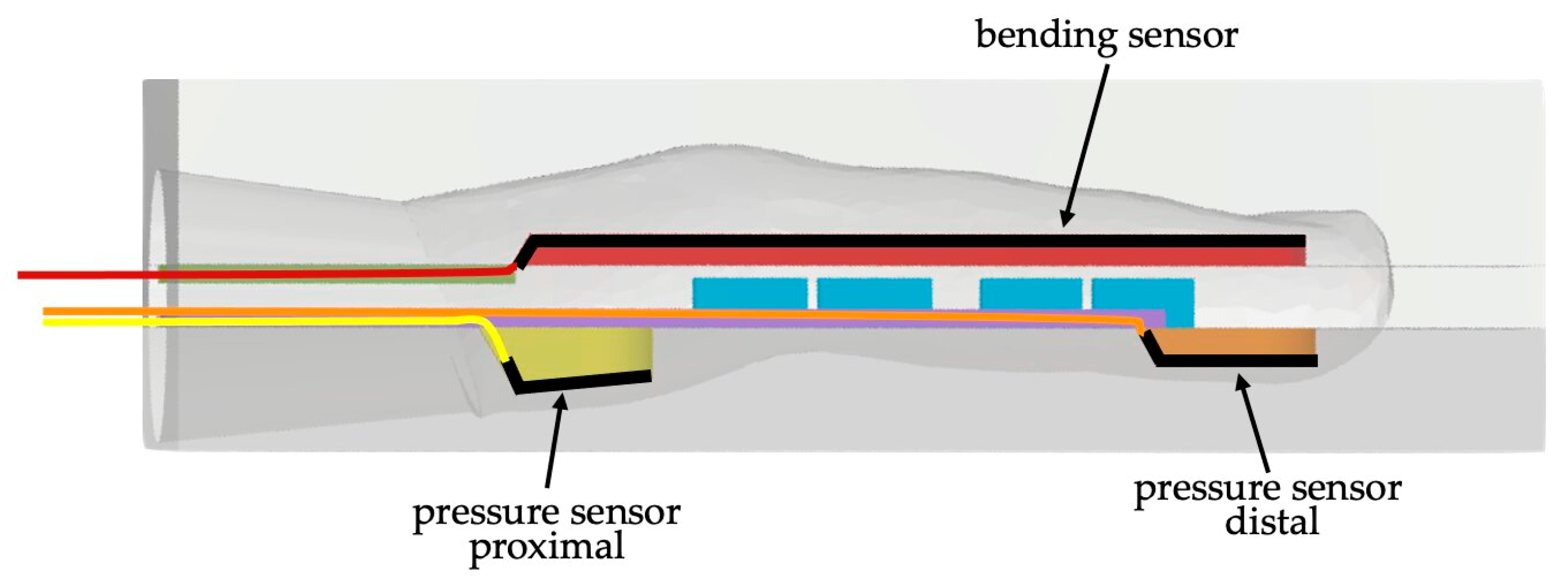
Figure 3 shows the intended inner structure of the finger after casting and integrating the sensors. The dorsal part of the finger contains the flex sensor (black) with its cables (red line). A red area above the sensor represents the cast “counterpart”, which ensures the fixed positioning. Its cable routing is shown as the green area, and the cable routing of the pressure sensors is purple. In this view, the different depths of the indentations for sensor placing can be seen. The proximal pressure sensor (gray, yellow placeholder) requires a deep and angled indentation, unlike the distal one (gray, orange placeholder). The cables of the proximal pressure sensor are represented by the yellow line, and those of the distal pressure sensor by the orange line. Blue cuboids represent the cavities that are meant to reduce stiffness.
In Figure 4, the first version of the lids for the new molds of the middle finger can be seen. The pressure sensors were installed in the palmar part of the finger; for this purpose, extrusions with the shape of the pressure sensors were installed in the lids (see Figure 4a). The angled ground of the proximal indentations allowed for parallel positioning of the sensors to the finger surface. Two depths of the indentations were tested for each sensor (distal: 3 mm resp. 2 mm, proximal: 5.5 mm resp. 3 mm). Two lids were needed for the mold of the middle part of the finger. The lid for the bottom (Figure 4b) had the cuboids for the cavities; the dimensions were those which were identified in the previous test series, with a reduced width to create more space for the integration of other structures. In addition, the placements of the distal and proximal cavities were off-centered to consider the natural curve of the finger. One finger had only the cavities; in two other fingers, cable routing was integrated to reduce possible tension caused by the cables. The upper lid (Figure 4c) had two structures for routing the cables of the flex sensor, and one part had no structure to create one finger without routing.
In the dorsal part of the finger, one flex sensor was integrated (Figure 4d). Thus, an extrusion was created to receive an indentation with the dimensions of the sensor. An additional mold was 3D-printed to create a placeholder, which ensures a safe placement of the sensors. The dimensions of the depths of the indentations were bigger than the heights of the sensors, potentially causing displacement of the sensors, which could lead to wrong or no measurable feedback.

2.4. Finger Test Series IV

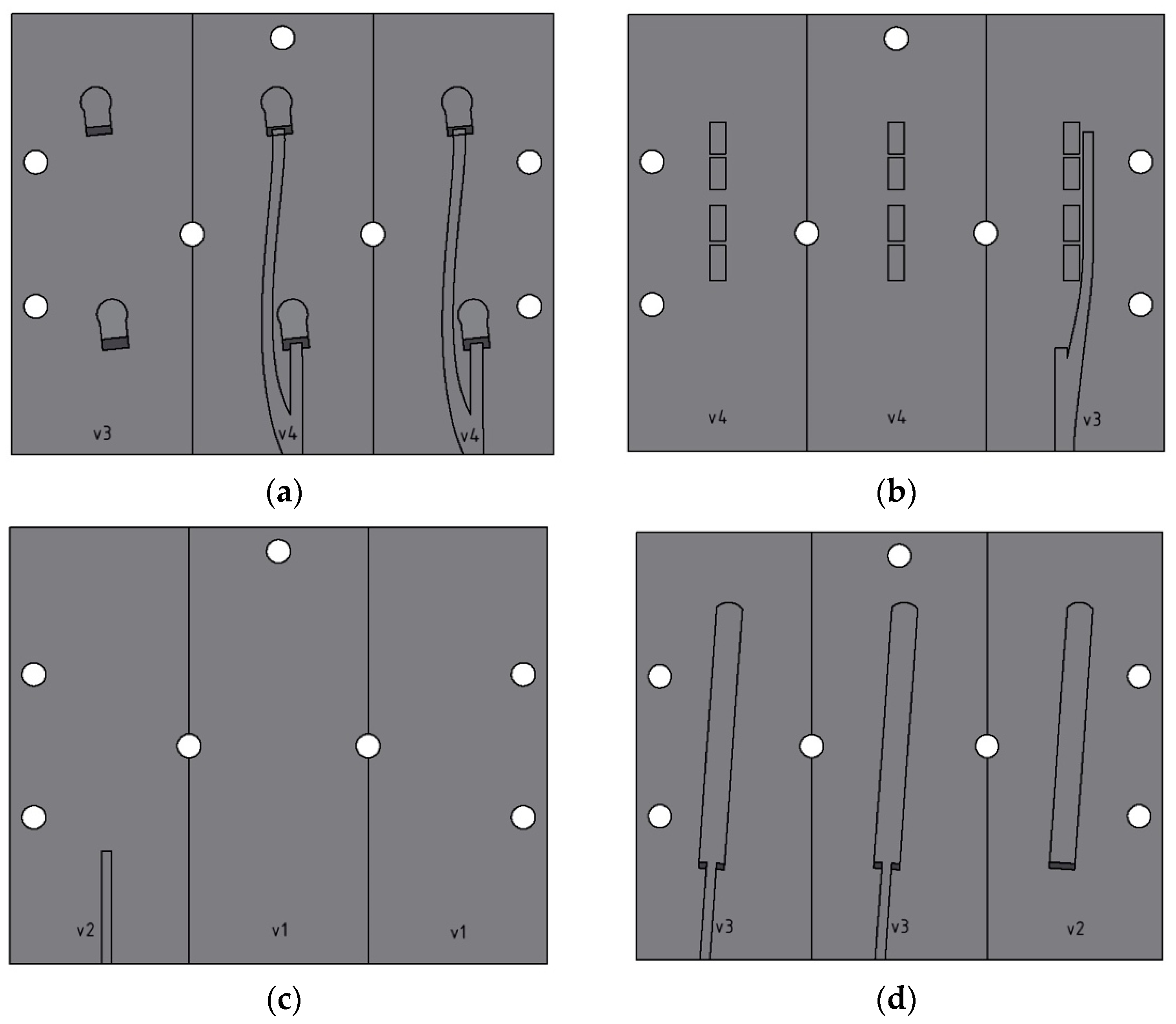
In this test series, the results of the previous were further refined, and the second versions of the lids were constructed, as shown in Figure 5. The depths of the positioning of the pressure sensors in the palmar part of the finger were 2 mm (distal) and 3 mm (proximal), and the taper was changed to 45 degrees instead of 30 degrees. Furthermore, the cable routing of the distal pressure sensor in the bottom lid of the middle finger part was placed more in the middle of the finger (Figure 5b, v3). Additionally, a concept was tested in which the cable routing was placed in the same part of the finger as the indentations, as seen in Figure 5a, v4 and Figure 5d, v3. The lids for the middle part of the finger were adapted accordingly (Figure 5b,c), as well as the lid for the dorsal finger part, as shown in Figure 5d. Here, the depth of the indentation for the bending sensor was decreased, and the length was increased.

2.5. Evaluation of Molded Pressure and Bending Sensors

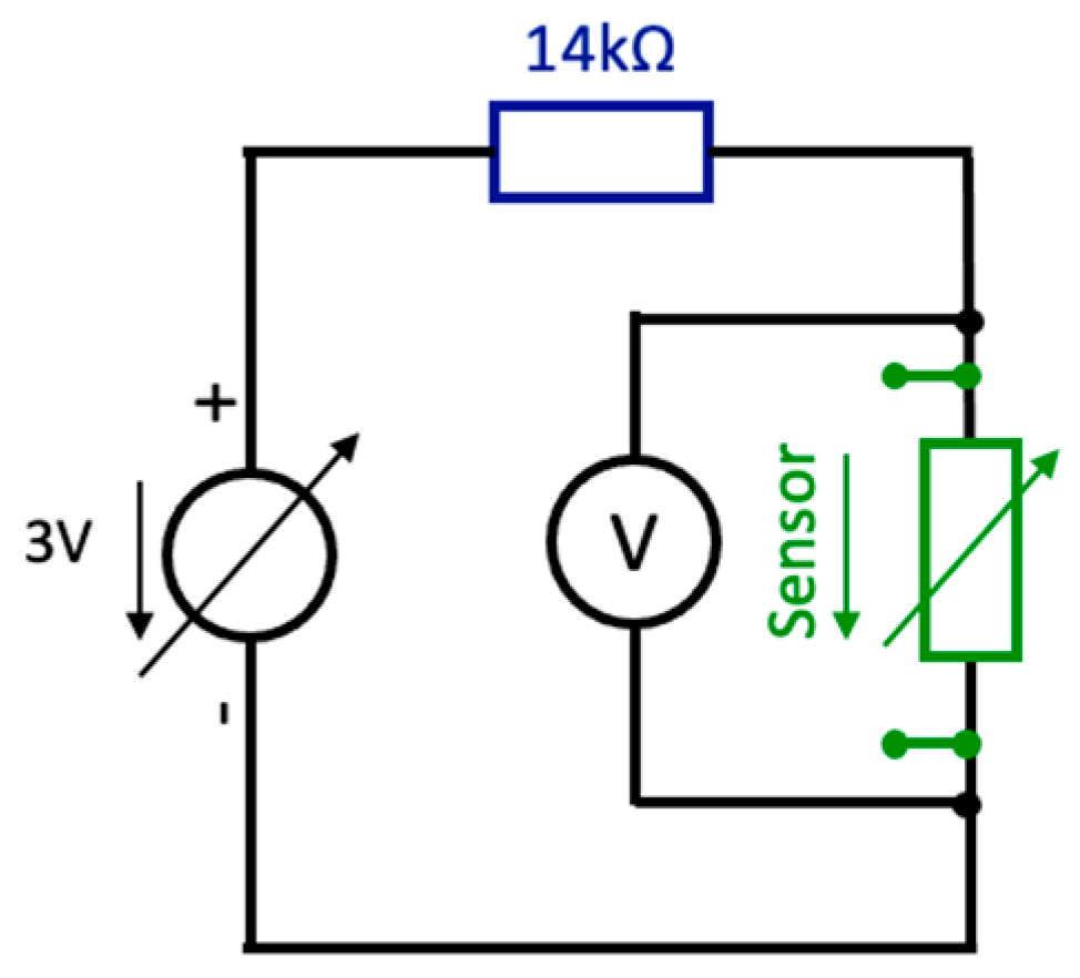
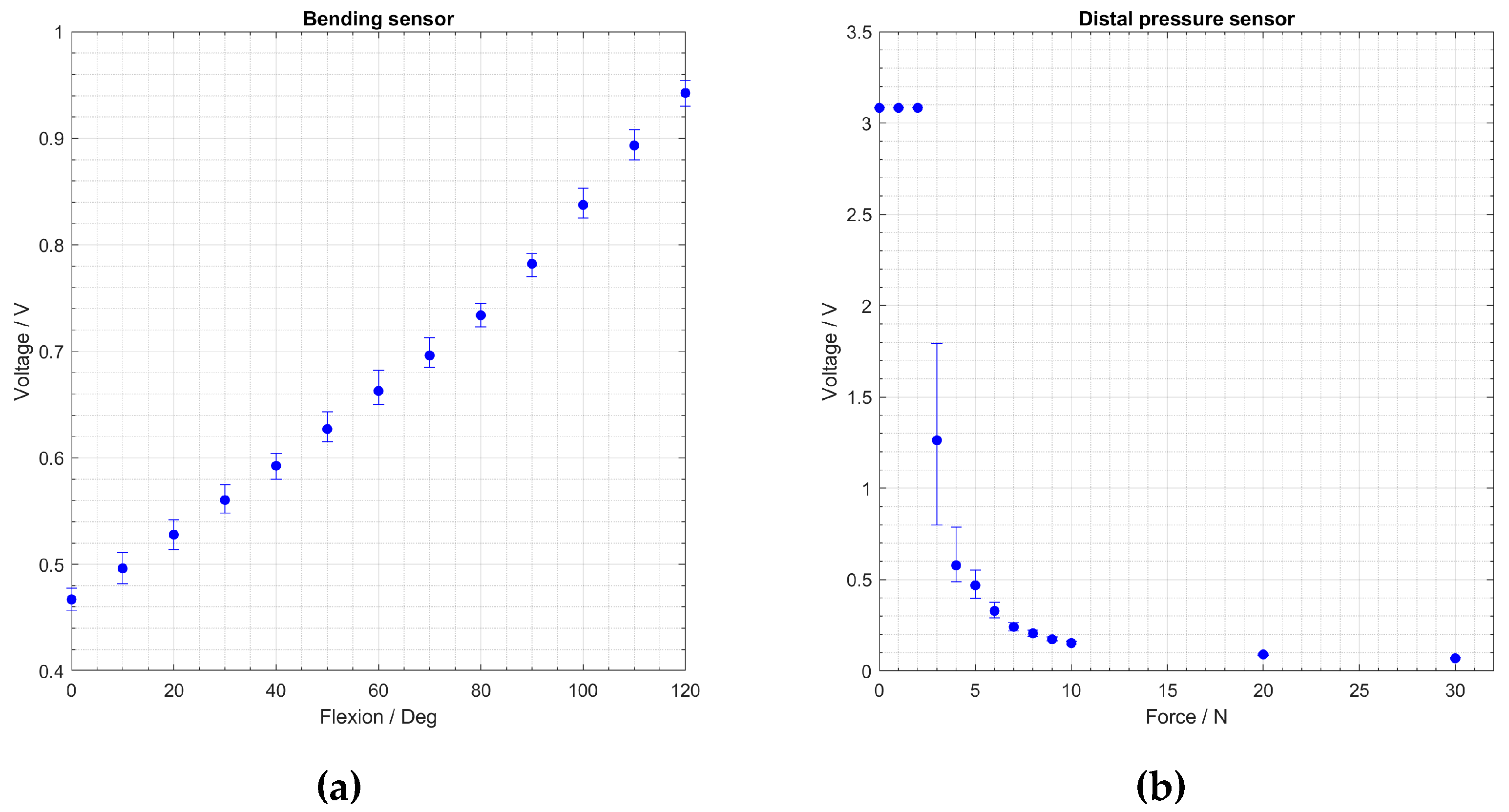
The individual analyses of the flex sensor and the pressure sensors were performed as a series of voltage measurements of the sensors of one finger using pressure/flexion. Both sensor types changed their resistance values due to pressure/flexion. Each sensor was implemented in a series circuit with a 14 kΩ resistor and a 3 V power source. The circuit diagram is shown in Figure 6. A multimeter measured the voltage change at the sensors due to a change in resistance with applied force or flexion. First, the feedback from the pressure sensor was tested. The finger was laid on its back and was mounted on a floating bar. Then, vertical forces from 0 to 10 N were applied in 1 N steps, and from 10 N to 30 N in 10 N steps. After each measurement, the finger returned to the unstressed state. At each force value, 10 measurements were conducted. For forces below 5 N, the load was initially increased to 5 N and then reduced to the corresponding value in order to avoid interference by the test setup. The applied force was measured by a force gauge. To evaluate the bending sensor, the finger was installed on a manual rotation table, which was adjusted in steps of 10 degrees from 0 to 120 degrees. Likewise, 10 test series were conducted. Further details about the test setup are given in [20].
Regarding the pressure sensor, measurements were only performed with the distal sensor. Since they are the same type of sensor, it can be assumed that both sensors showed similar behavior.

2.6. Final Replacement Hand

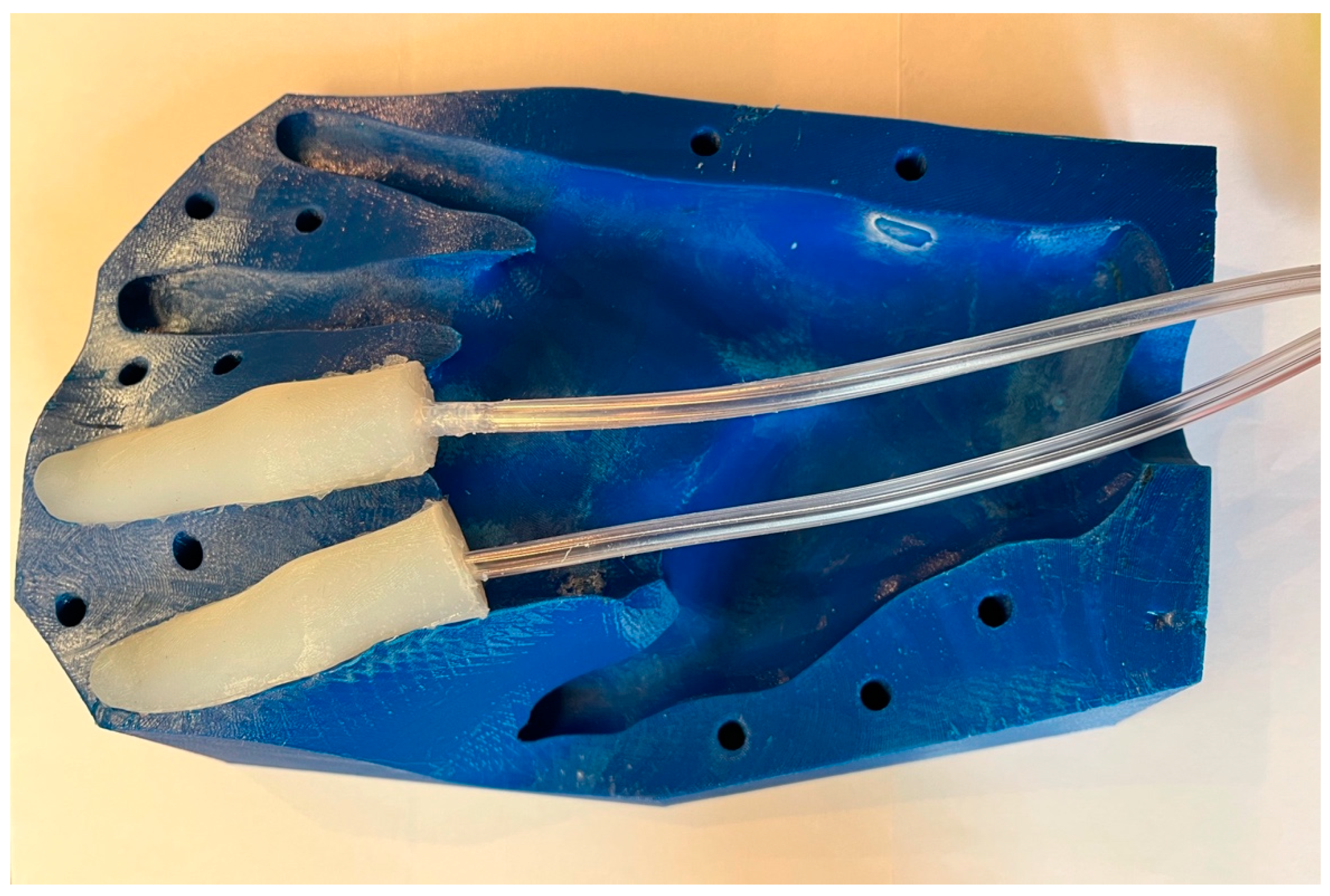
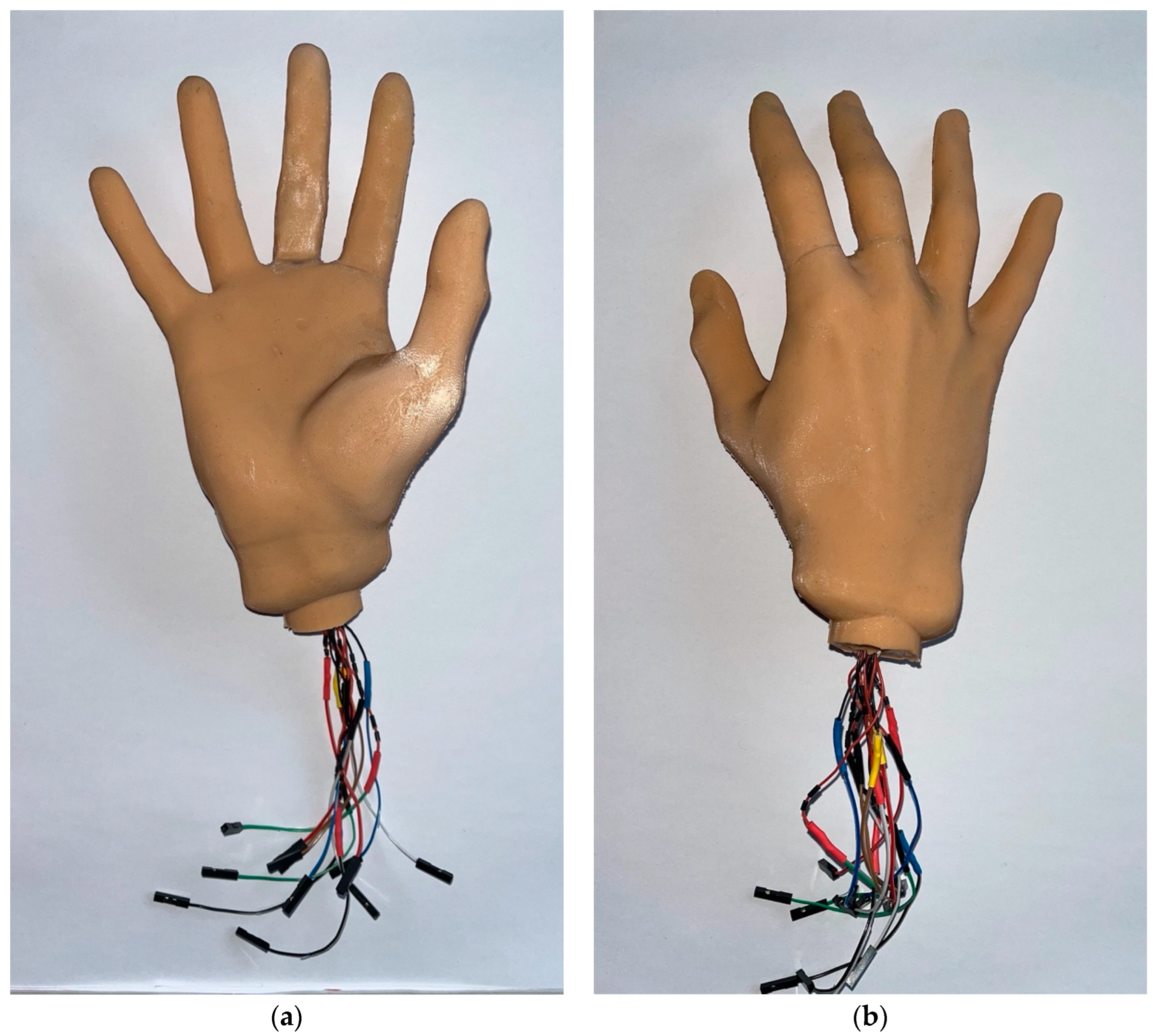
The final replacement hand was cast, and the middle and index fingers were produced separately and glued to the rest of the hand. For this purpose, the mold of Hazubski et al. [20] was used. The placeholders of the index and middle fingers were cast using silicone with a Shore hardness of ShA20. To create cable routing through the rest of the hand, plastic tubes were integrated into the fingers, which could be removed after vulcanization. In Figure 7, the palmar part of the mold of Hazubski et al. [20] with the inserted placeholder fingers and the tubes is shown. The middle and index fingers with inserted sensors were added to the rest of the hand, and subsequently, measurements of the sensors in the index finger were performed during the grasping process of different objects. Figure 8a shows the palmar view and Figure 8b shows the dorsal view of the final anthropomorphic replacement hand with the integrated pressure and flex sensors. The SILIXON10 was colored with a color paste with the tone “European 3”, using a mixing ratio of approximately 7 g per 1000 g of silicone.
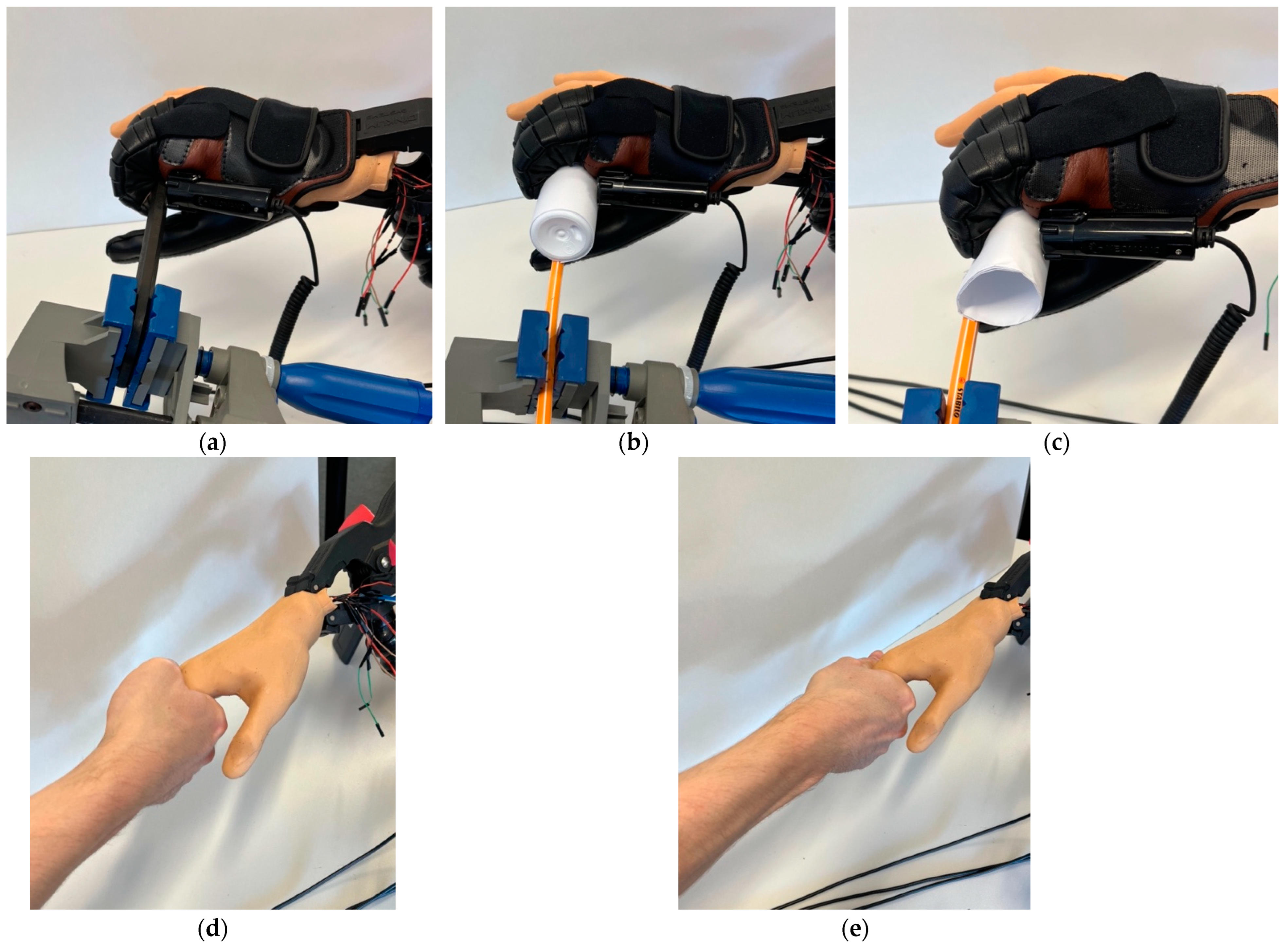
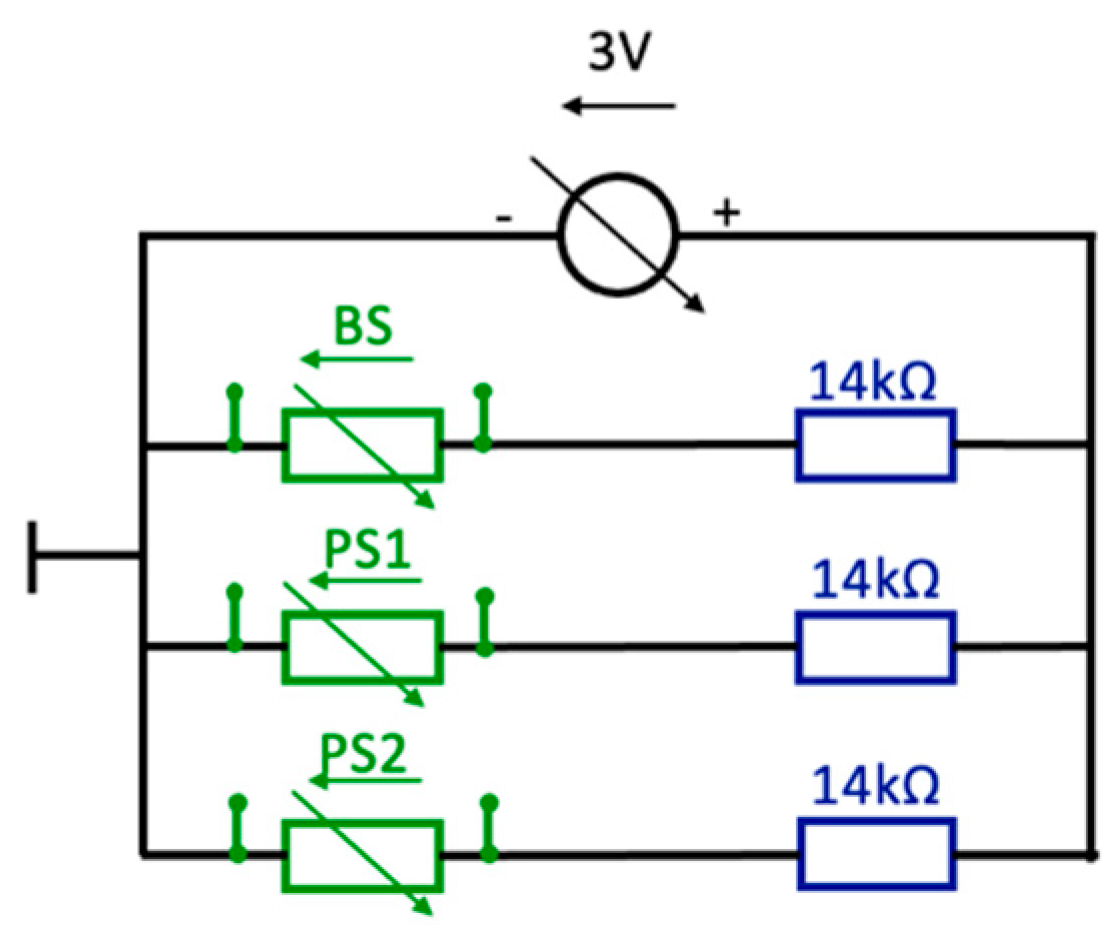
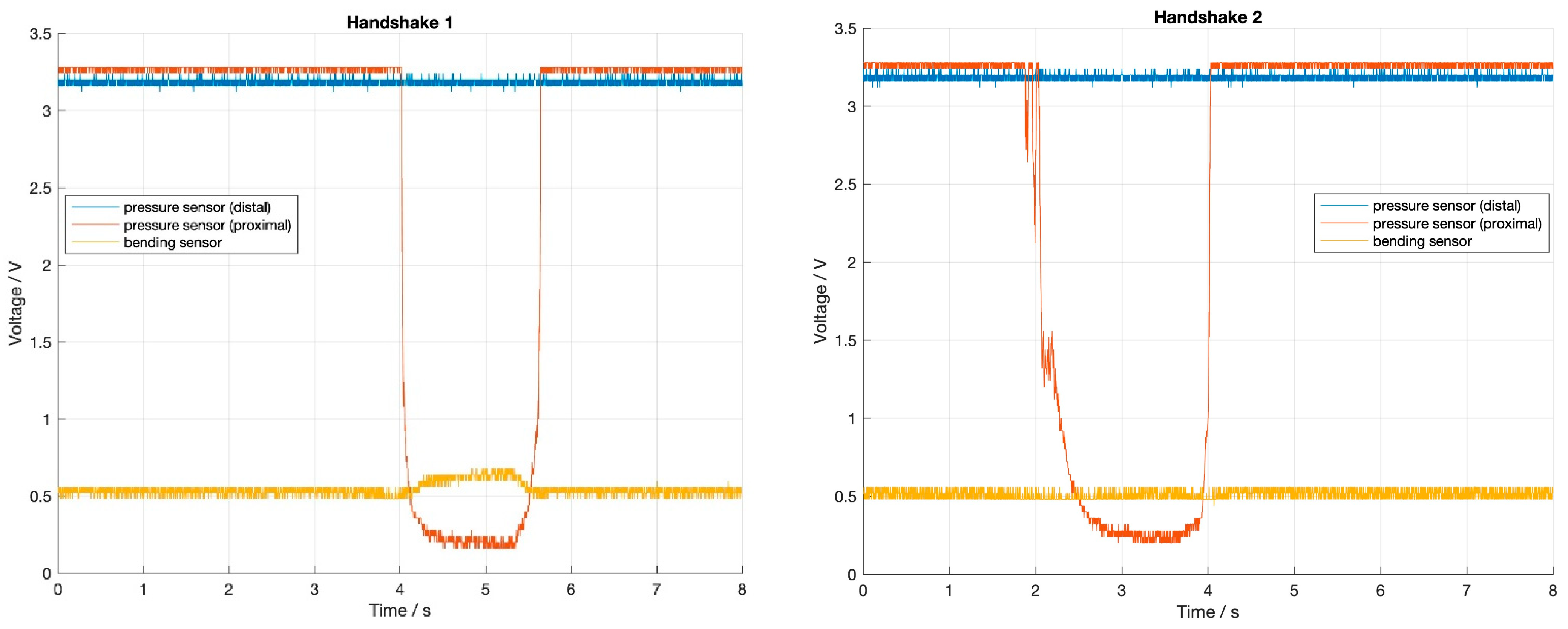
To test the replacement hand, shown in Figure 8, the same objects as in Hazubski et al. [20] were used, namely a thin tool, a plastic bottle, and a paper roll. Figure 9a–c as well as Videos S1–S3 show the final replacement hand while grasping a thin tool, a plastic bottle, and a paper roll using a NeoMano orthosis. To evaluate the sensory feedback without using the NeoMano orthosis, two different types of handshakes were performed. For this, the resistance of the sensors in the middle finger was measured. First, the hand was fully grasped and all four fingers were loaded (Figure 9d). During the second handshake, the hand was also fully grasped, but the middle finger was particularly loaded (Figure 9e). For the measurements, the circuit shown in Figure 10 was used. Every sensor was implemented in a series circuit with a 14 kΩ resistance. The three series circuits and the 3 V voltage source were connected as a parallel circuit.

3. Results

3.1. Finger Test Series I

Regarding the possibility of adherence, it appeared that the bond seam did not differ from the seam that occurred by using a two-part mold. Moreover, the bond happened to be strong even under repeated movement and high-dynamic loading. This implies that the approach of producing several components and assembling them afterwards could be pursued.
The geometries inside of the finger appeared to be placed wrong; it is necessary that these are located at the level of the joints. This is because the flexion of the finger takes place in the joints. Furthermore, the fingers were still too rigid and could not be completely bent by the orthosis.

3.2. Finger Test Series II

A lower stiffness could be recognized during the consideration of the flexibility of these fingers. This was confirmed by using the orthosis. The finger with the cuboids with the following dimensions ( w i d t h × h e i g h t × d e p t h ) can be bent completely: proximal dimensions of 5 × 9 × 4   mm , distal dimensions of 5 × 8 × 4   mm . Furthermore, the cavities seemed to be placed at the height of the joint; this can be confirmed during manufacturing and when considering the flexibility.

3.3. Finger Test Series III

During manufacturing, it can be seen that the cable routing of the distal pressure sensor was not placed ideally, and putting in the cables was inconvenient. Furthermore, the cable routing at the level of the cavities was placed too close to the outside of the finger. These were visible and palpable after gluing. Therefore, they were placed more in the center of the finger in the next test series. It was also seen that the distal pressure sensor, which was placed in the deeper indentation, was not covered enough, and the risk of penetrating the material was high. The same issue applied to the flex sensor. Both sensors were thus placed in shallower indentations in further tests. In addition, the indentation of the flex sensor was too short. The attempt to flex the fingers using the NeoMano orthosis showed that it is possible to achieve full flexion.

3.4. Finger Test Series IV

The cable routing of the pressure sensor in the palmar part of the finger was too deep, which caused defects in the surface of the finger. The height of the routing could not be lowered, otherwise, the cables would no longer fit inside. Since the manufacturing was hardly simplified by this change, inserting the cable routing into the middle part of the finger was continued. The positioning of the sensors seemed to be correct; they no longer shone through the surface and were only palpable with strong pressure.

3.5. Evaluation of Molded Pressure and Bending Sensors

In Figure 11, the feedback of the flex sensor can be seen, showing a proportional behavior. Both pressure sensors behaved similarly, and the resistance decreased exponentially with increasing pressure. Besides the large scattering of the pressure sensor at 3 N, the sensors gave reproducible results. For the bending sensor, a small drift of up to 30 mV was observed in the first 20 s at a new bending level. The sensor values were measured after a few seconds since, under real-life conditions, a long dwell time is not tolerable. Nevertheless, without drifting, the scattering of the bending sensor would have been smaller.

3.6. Final Replacement Hand

As can be seen in Figure 12, during the first handshake, the proximal pressure sensor and the flex sensor registered changes in the signal; during the second handshake, only the proximal pressure sensor showed a shift.
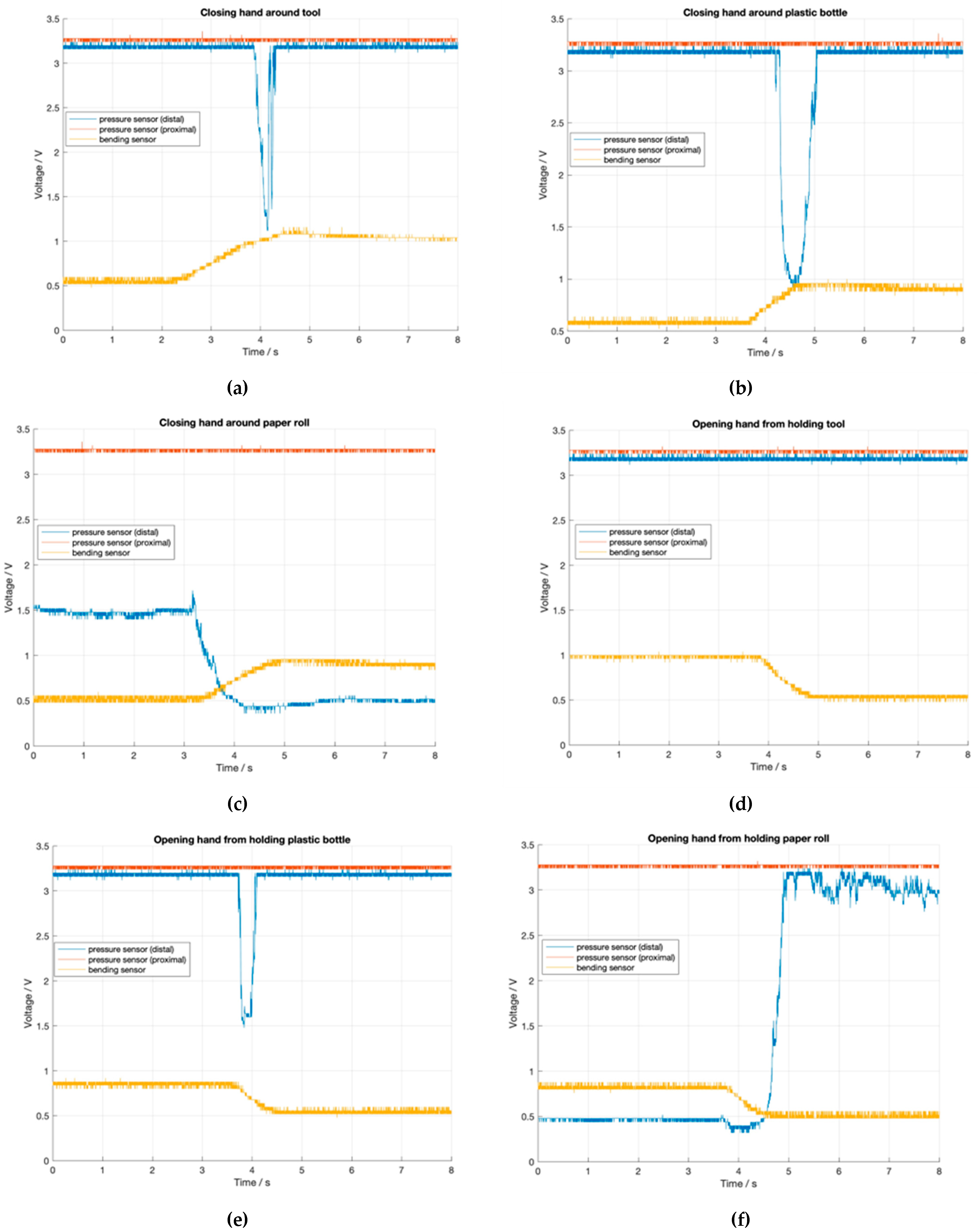
In Figure 13, the results of the measurements during the grasping of different objects can be seen. These show consistent results of the bending sensors during grasping a thin tool, a paper roll, and a plastic bottle. For the pressure sensors, it was noticed that the distal sensor received a signal, but only during the movement; afterwards, the signal disappeared. This effect can be explained by the design of the orthosis. Since the finger and glove were not tightly connected, the finger did not flex uniformly but could move slightly inside the glove. The proximal sensor did not register any signal. The behavior of the proximal sensor is explained by the design of the motorized orthosis as well. The tendon of the glove was guided directly in front of this sensor, which blocked the grasped object from the sensor. Both effects are also described in [20].

4. Discussion

All results were verified through different test series. Individual measurements of the flex sensor and pressure sensors show that the sensors registered consistent signals even after repeated loading, which is shown in Figure 11. This proves that the placement of the sensors by using indentations was suitable and prevented them from slipping out of place. In addition, the integration of cavities allowed for full flexion of the fingers with the sensors by using a NeoMano orthosis.
The final tests registered the sensory feedback as voltage measurements above the sensors during different loading situations. These reliably provided comprehensive results even after repeated loading. Furthermore, it was observed that objects with both smaller diameters (here, a thin tool) and larger ones (here, a plastic bottle and a paper roll) could be grasped. The NeoMano orthosis caused reduced sensitivity due to its material and the cord that flexed the finger during the grasping process, which spanned between the object and the sensor in such a way that the sensors were unaffected by the object. Nevertheless, a clear change in the resistance of the sensors was registered. The recorded behavior of the sensors after the end of a movement (opening/closing) indicates that the sensors were sufficiently supported in the fingers. This can be concluded by the fact that the change in resistance only lasted for the duration of the sustained loading, as can be seen in the measurements of grasping the tool (Figure 13a) and the plastic bottle (Figure 13b). During the measurements of the sensors of the index finger, no feedback was recorded by the proximal pressure sensor. Since all sensors were checked for functionality prior to the measurements with the orthosis and no malfunction was recorded, it can be assumed that the sensor was damaged during the repeated movements. The rigid and relatively large solder tails of the sensors were recognized as the major potential sources of failure during the bending of the fingers. Another promising sensor for dynamic tactile feedback was proposed in [22]. Here, a MEMS sensor was used in combination with a fluid-filled cavity under the skin to measure the micro-vibrations of an object that was slipping through the fingers. In future projects, the use of new, smaller sensors, or even sensor arrays, for example, printed foil sensors, can be considered [9,23]. Such sensors are not only reduced in size but are additionally highly flexible.
Future research may cover the signal processing of sensory feedback as well as the output of the feedback to the user. For example, using a microcontroller could offer different possibilities for the patient to receive processed sensory feedback (visual, vibrotactile, etc.), as has been presented in many prominent studies [18,24,25]. Another field for further research is the distinction between process-related feedback signals and feedback signals due to the actual grasping action. In the results of the measurements with the subcutaneously attached pressure sensors, some signals were identified that were caused by the setting with the motorized orthosis. These signals would probably irritate the user and should therefore be filtered in a reasonable form or avoided in further design-related adjustments.

5. Conclusions

This work shows that it is possible to create an anthropomorphic replacement hand with a sensory feedback system that requires little material input and simple manufacturing processes. Creating a mold based on a 3D scan of a hand proved to be a suitable option for a replacement hand. The design of the mold using computer-aided design allows the integration of further adjustments, such as inner structures or detaching the fingers from the rest of the hand. Three-dimensional printing proved to be a suitable manufacturing process for the individually designed mold, which was easy to handle and low in cost.
Using a color paste, the natural look of the hand can be further enhanced by creating a skin tone similar to the patient´s; this also increases patient acceptance. Due to the possibility of bonding vulcanized silicone material with the adhesive Silpuran 4200, the middle and index fingers can be cast separately from the rest of the hand and in three parts. This enables the adaptation of the internal structures of the fingers so that the sensors can be placed securely and easily. In addition, by integrating cavities, the stiffness of the fingers can be reduced, which leads to the possibility of bending the fingers completely using a NeoMano orthosis despite integrated sensors and the use of SILIXON10. Furthermore, the use of only one silicone simplified the manufacturing process.

Supplementary Materials

The following supporting information can be downloaded at: https://www.mdpi.com/article/10.3390/prosthesis4040055/s1, Video S1: Grasping of paper roll, Video S2: Grasping of plastic bottle, Video S3: Grasping of thin tool.

Author Contributions

Conceptualization, S.H., L.A. and A.O.; methodology, L.A. and S.H.; validation, S.H., L.A. and A.O.; formal analysis, L.A. and S.H.; investigation, L.A.; data curation, S.H. and L.A.; writing—original draft preparation, L.A.; writing—review and editing, L.A., S.H. and A.O.; visualization, L.A. and S.H.; supervision, S.H. and A.O.; project administration, A.O. All authors have read and agreed to the published version of the manuscript.

Funding

This research received no external funding.

Institutional Review Board Statement

Not applicable.

Informed Consent Statement

Not applicable.

Data Availability Statement

Data sharing not applicable.

Acknowledgments

The 3D printing of the mold was supported by the Edu FabLab of Offenburg University, which is co-funded by the Baden-Württemberg Ministry of Science, Research and Culture.

Conflicts of Interest

This paper contains parts of the Master’s Thesis of L.A., which was supervised by S.H. and A.O., 2022 (see [26]).

References

  1. Siotos, C.; Ibrahim, Z.; Bai, J.; Payne, R.M.; Seal, S.M.; Lifchez, S.D.; Hyder, A.A. Hand Injuries in Low- and Middle-Income Countries: Systematic Review of Existing Literature and Call for Greater Attention. Public Health 2018, 162, 135–146. [Google Scholar] [CrossRef] [PubMed]
  2. Imbinto, I.; Peccia, C.; Controzzi, M.; Cutti, A.G.; Davalli, A.; Sacchetti, R.; Cipriani, C. Treatment of the Partial Hand Amputation: An Engineering Perspective. IEEE Rev. Biomed. Eng. 2016, 9, 32–48. [Google Scholar] [CrossRef] [PubMed]
  3. Kim, G.M.; Powell, J.E.; Lacey, S.A.; Butkus, J.A.; Smith, D.G. Current and Emerging Prostheses for Partial Hand Amputation: A Narrative Review. PM R. 2022. Online ahead of print. [Google Scholar] [CrossRef] [PubMed]
  4. D’Anna, E.; Petrini, F.M.; Artoni, F.; Popovic, I.; Simanić, I.; Raspopovic, S.; Micera, S. A Somatotopic Bidirectional Hand Prosthesis with Transcutaneous Electrical Nerve Stimulation Based Sensory Feedback. Sci. Rep. 2017, 7, 10930. [Google Scholar] [CrossRef] [PubMed]
  5. Silcox, D.H.; Rooks, M.D.; Vogel, R.R.; Fleming, L.L. Myoelectric Prostheses. A Long-Term Follow-up and a Study of the Use of Alternate Prostheses. J. Bone Jt. Surg. 1993, 75, 1781–1789. [Google Scholar] [CrossRef] [PubMed]
  6. Crandall, R.C.; Tomhave, W. Pediatric Unilateral Below-Elbow Amputees: Retrospective Analysis of 34 Patients Given Multiple Prosthetic Options. J. Pediatr. Orthop. 2002, 22, 380–383. [Google Scholar] [CrossRef]
  7. Schweisfurth, M.A.; Markovic, M.; Bentz, T.; Wüstefeld, D.; Farina, D.; Dosen, S. Sensorisches Feedback in der Handprothetik. Orthopädietechnik 2017, 68, 34–38. [Google Scholar]
  8. Brochier, T.; Boudreau, M.-J.; Paré, M.; Smith, A.M. The Effects of Muscimol Inactivation of Small Regions of Motor and Somatosensory Cortex on Independent Finger Movements and Force Control in the Precision Grip. Exp. Brain Res. 1999, 128, 31–40. [Google Scholar] [CrossRef]
  9. Liang, Z.; Cheng, J.; Zhao, Q.; Zhao, X.; Han, Z.; Chen, Y.; Ma, Y.; Feng, X. High-Performance Flexible Tactile Sensor Enabling Intelligent Haptic Perception for a Soft Prosthetic Hand. Adv. Mater. Technol. 2019, 4, 1900317. [Google Scholar] [CrossRef]
  10. Anwer, A.H.; Khan, N.; Ansari, M.Z.; Baek, S.-S.; Yi, H.; Kim, S.; Noh, S.M.; Jeong, C. Recent Advances in Touch Sensors for Flexible Wearable Devices. Sensors 2022, 22, 4460. [Google Scholar] [CrossRef] [PubMed]
  11. Panescu, D. MEMS in Medicine and Biology. IEEE Eng. Med. Biol. Mag. 2006, 25, 19–28. [Google Scholar] [CrossRef] [PubMed]
  12. Farserotu, J.; Baborowski, J.; Decotignie, J.-D.; Dallemagne, P.; Enz, C.; Sebelius, F.; Rosen, B.; Antfolk, C.; Lundborg, G.; Bjorkman, A.; et al. Smart Skin for Tactile Prosthetics. In Proceedings of the 2012 6th International Symposium on Medical Information and Communication Technology (ISMICT), La Jolla, CA, USA, 25–29 March 2012; IEEE: La Jolla, CA, USA, 2012; pp. 1–8. [Google Scholar]
  13. Sensinger, J.W.; Dosen, S. A Review of Sensory Feedback in Upper-Limb Prostheses From the Perspective of Human Motor Control. Front. Neurosci. 2020, 14, 345. [Google Scholar] [CrossRef] [PubMed]
  14. Antfolk, C.; D’Alonzo, M.; Controzzi, M.; Lundborg, G.; Rosen, B.; Sebelius, F.; Cipriani, C. Artificial Redirection of Sensation From Prosthetic Fingers to the Phantom Hand Map on Transradial Amputees: Vibrotactile Versus Mechanotactile Sensory Feedback. IEEE Trans. Neural Syst. Rehabil. Eng. 2013, 21, 112–120. [Google Scholar] [CrossRef]
  15. Antfolk, C.; Björkman, A.; Frank, S.; Sebelius, F.; Lundborg, G.; Rosen, B. Sensory Feedback from a Prosthetic Hand Based on Air-Mediated Pressure from the Hand to the Forearm Skin. J. Rehabil. Med. 2012, 44, 702–707. [Google Scholar] [CrossRef] [Green Version]
  16. Childress, D.S. Closed-Loop Control in Prosthetic Systems: Historical Perspective. Ann. Biomed. Eng. 1980, 8, 293–303. [Google Scholar] [CrossRef]
  17. Jabban, L.; Dupan, S.; Zhang, D.; Ainsworth, B.; Nazarpour, K.; Metcalfe, B.W. Sensory Feedback for Upper-Limb Prostheses: Opportunities and Barriers. IEEE Trans. Neural Syst. Rehabil. Eng. 2022, 30, 738–747. [Google Scholar] [CrossRef] [PubMed]
  18. Stephens-Fripp, B.; Alici, G.; Mutlu, R. A Review of Non-Invasive Sensory Feedback Methods for Transradial Prosthetic Hands. IEEE Access 2018, 6, 6878–6899. [Google Scholar] [CrossRef]
  19. Cabibihan, J.-J.; Alkhatib, F.; Mudassir, M.; Lambert, L.A.; Al-Kwifi, O.S.; Diab, K.; Mahdi, E. Suitability of the Openly Accessible 3D Printed Prosthetic Hands for War-Wounded Children. Front. Robot. AI 2021, 7, 594196. [Google Scholar] [CrossRef]
  20. Hazubski, S.; Bamerni, D.; Otte, A. Conceptualization of a Sensory Feedback System in an Anthropomorphic Replacement Hand. Prosthesis 2021, 3, 415–427. [Google Scholar] [CrossRef]
  21. Cacucciolo, V.; Shintake, J.; Kuwajima, Y.; Maeda, S.; Floreano, D.; Shea, H. Stretchable Pumps for Soft Machines. Nature 2019, 572, 516–519. [Google Scholar] [CrossRef]
  22. Fishel, J.A.; Santos, V.J.; Loeb, G.E. A Robust Micro-Vibration Sensor for Biomimetic Fingertips. In Proceedings of the 2008 2nd IEEE RAS & EMBS International Conference on Biomedical Robotics and Biomechatronics, Scottsdale, AZ, USA, 19 October 2008; pp. 659–663. [Google Scholar]
  23. Hari M., A.; Rajan, L. Advanced Materials and Technologies for Touch Sensing in Prosthetic Limbs. IEEE Trans. NanoBioscience 2021, 20, 256–270. [Google Scholar] [CrossRef] [PubMed]
  24. Engeberg, E.D.; Meek, S. Enhanced Visual Feedback for Slip Prevention with a Prosthetic Hand. Prosthet Orthot. Int. 2012, 36, 423–429. [Google Scholar] [CrossRef] [PubMed]
  25. Dietrich, C.; Walter-Walsh, K.; Preißler, S.; Hofmann, G.O.; Witte, O.W.; Miltner, W.H.R.; Weiss, T. Sensory Feedback Prosthesis Reduces Phantom Limb Pain: Proof of a Principle. Neurosci. Lett. 2012, 507, 97–100. [Google Scholar] [CrossRef] [PubMed]
  26. Allmendinger, L. Konzeptionierung einer anthropomorphen Ersatzhand mit sensorischem Feedback. Master’s Thesis, Offenburg University, Offenburg, Germany, 2022. [Google Scholar]
Figure 1. (a) First version of the lid (palmar finger segment) for the molds of Hazubski et al. [20] with different geometries of the cavities, (b) second version of the lid (palmar finger segment) for the molds of Hazubski et al. [20] with cuboids with different dimensions.
Prosthesis 04 00055 g001
Figure 2. Three-dimensional model of the middle finger, with two working planes to separate it into three segments.
Prosthesis 04 00055 g002
Figure 3. Three-dimensional model of the mold for the middle finger (side view) with inserted structures. Black: sensors; red object above bending sensor: placeholder flex sensor; yellow/brown objects above pressure sensors: placeholder for pressure sensor; green/purple: cable routing for flex and pressure sensor; blue: cavities; red line: cables of the bending sensor; orange and yellow line: cables of the pressure sensors.
Prosthesis 04 00055 g003
Figure 4. First versions of the lids for the different molds of the finger segments. (a) Lid for the palmar mold, with extrusion for positioning the pressure sensors, (b) lid for underneath the mold of the middle part, with extrusions for the cavities and cable routing of the pressure sensors, (c) lid for the top of the mold of the middle part, with extrusions for cable routing, (d) lid for the dorsal mold with extrusions for positioning the bending sensor.
Prosthesis 04 00055 g004
Figure 5. Second version of the lids for the different molds of the finger segments. (a) Lid for the palmar mold, with extrusion for positioning the pressure sensors and cable routing, (b) lid for underneath the mold of the middle part, with extrusions for the cavities and cable routing of the pressure sensors, (c) lid for the top of the mold of the middle part, with extrusion for cable routing, (d) lid for the dorsal mold, with extrusions for positioning the bending sensor and cable routing.
Prosthesis 04 00055 g005
Figure 6. Schematic of the circuit for individual evaluating the sensors with a 14 kΩ resistor, voltage source, sensor, and a parallel wired multimeter.
Prosthesis 04 00055 g006
Figure 7. Palmar part of the mold of Hazubski et al. [20] with inserted placeholder fingers and tubes for creating cable routing through the hand.
Prosthesis 04 00055 g007
Figure 8. Final anthropomorphic replacement hand with integrated pressure and flex sensors. (a) palmar view; (b) dorsal view.
Prosthesis 04 00055 g008
Figure 9. (a) Final replacement hand grasping a thin tool using NeoMano orthosis, (b) final replacement hand grasping a plastic bottle using NeoMano orthosis, (c) final replacement hand grasping a paper roll using NeoMano orthosis, (d) first handshake, fully grasped hand, and all four fingers loaded, (e) second handshake, fully grasped, middle finger particularly loaded.
Prosthesis 04 00055 g009
Figure 10. Schematic of the circuit for evaluating the sensors with three 14 kΩ resistors, voltage source, the two pressure sensors (PS1 and PS2), and the bending sensor (BS).
Prosthesis 04 00055 g010
Figure 11. (a) Results of the voltage measurements of the flex sensor at flexion from 0 degrees to 120 degrees, (b) results of the voltage measurements of distal pressure sensor under load from 0 N to 30 N.
Prosthesis 04 00055 g011
Figure 12. Measurements of the sensor feedback during two different types of handshakes.
Prosthesis 04 00055 g012
Figure 13. Measurements of the sensor feedback while grasping different objects. (a) Sensory feedback while closing hand around a thin tool, (b) sensory feedback while closing hand around a plastic bottle, (c) sensory feedback while closing hand around a paper roll, (d) sensory feedback while opening hand from holding a thin tool, (e) sensory feedback while opening hand from holding a plastic bottle, (f) sensory feedback while opening hand from holding a paper roll.
Prosthesis 04 00055 g013
Table 1. Table of measurements of the cuboids used in the second version of the lid for palmar and dorsal finger segments.
DistalProximal
PalmarDorsalPalmarDorsal
v6 6 × 4 × 3   mm 6 × 4 × 2.5   mm 7 × 4 × 3   mm 7 × 4 × 2.5   mm
v7 6 × 4 × 4   mm 6 × 4 × 2.5   mm 7 × 4 × 4   mm 7 × 4 × 2.5   mm
v8 6 × 4 × 5   mm 6 × 4 × 2.5   mm 7 × 4 × 5   mm 7 × 4 × 2.5   mm
v9 8 × 5 × 4   mm 8 × 5 × 2.5   mm 9 × 5 × 4   mm 9 × 5 × 2.5   mm
v10 9 × 5 × 4   mm 9 × 5 × 2.5   mm 9 × 5 × 4   mm 9 × 5 × 2.5   mm
Publisher’s Note: MDPI stays neutral with regard to jurisdictional claims in published maps and institutional affiliations.