


Abstract
Modern vehicles feature an increasing number of automated driving functions. This raises formal safety requirements for systems that directly intervene with these functions, such as steering or braking systems. The state-of-the-art offers various solutions that ensure fail-operational capability of safety-relevant systems. However, many existing approaches are associated with increased material and integration effort, particularly when applied to existing automotive E/E architectures. This paper proposes a capacitor-based Safety Adapter to address this gap. It is intended to support the fulfillment of higher functional safety requirements under ISO 26262. We derive formal safety requirements based on an exemplary steering system and also present a first possible hardware layout. Initial verification results on a HiL test bench indicate that the proposed Safety Adapter can maintain steering assistance during undervoltage scenarios, even under aged conditions and very low ambient temperatures.
1. Introduction
The complexity of electrical and electronic (E/E) systems in modern vehicles continues to rise [1]. In addition to the growing number of comfort systems, safety-relevant systems are increasingly taking over driving tasks. First implementations of SAE Level 3 systems are already available on the market [2]. This level of automation allows the driver to temporarily engage in activities other than driving. Such Advanced Driving Assistance Systems (ADASs) as well as upcoming steer-by-wire technologies render the driver unavailable as a fallback in case the safety-relevant systems fail.
To address these challenges, redundancies, new zonal architectures, and in particular electronic fuses (eFuses) are used to ensure robustness of future automotive E/E architectures. eFuses trip faster than conventional automotive fuses and are therefore able to prevent undervoltages within safety-relevant systems, e.g., in the event of a short circuit in a parallel system. On the other hand, eFuses are costly and their integration into existing E/E architectures is complex. This leads to the challenge that existing E/E architectures can hardly be upgraded economically with the aforementioned ADAS technologies in mid-cycle refreshes.
The aim of this work is to develop an energy storage system with reduced integration requirements that is positioned between the safety-relevant system and the remaining wiring harness and enables ISO 26262-compliant integration of functions with high-level safety goals. The system is designed as an external measure with regard to ISO 26262 and addresses selected integration challenges of centralized and eFuse-based approaches, particularly when additional safety-relevant functions are introduced into existing vehicle architectures.
The following sections include a literature review on the aforementioned challenges within future automotive E/E architectures and potential solution approaches. Subsequently, the concept of a capacitor-based energy storage system is introduced. The derivation of functional safety requirements from the higher-level safety-relevant system to the external measure is discussed afterwards. A preliminary hardware layout is then presented. Finally, initial verification results from a steering system HiL test bench are discussed to evaluate the feasibility of the concept under representative undervoltage scenarios.
2. Literature Review
A targeted literature review was conducted to assess the current state of research and technological advancements in fail-operational power supply networks for automated vehicles. The review focused primarily on the SCOPUS and IEEE Xplore databases. Relevant publications were identified through combinations of the keywords Functional Safety, ISO 26262, Freedom from Interference, Electronic Fuse, Fail-Operational, Vehicle Powernet, ADAS, ADS, ASIL Decomposition, and Emergency Operation. Approximately 70 publications were reviewed in detail, focusing on safety-relevant low-voltage architectures within the automotive domain. Studies unrelated to automotive applications or centered on high-voltage systems were excluded.
2.1. Emerging Trends and Safety Implications
One significant trend in modern vehicle development is the steady increase in vehicle mass and axle loads [3]. This development is primarily driven by the electrification of powertrains, the integration of ADAS technologies, increasingly complex electronic architectures, and the global shift in consumer preference toward heavier vehicle segments such as SUVs [4]. These changes have direct implications for the design of the Electric Power Steering (EPS). As axle loads increase, the manual steering torque required in the event of an EPS failure also rises, potentially exceeding the physical capabilities of the driver during low-speed maneuvers or sudden evasive actions. This loss of steering assistance can critically impair vehicle controllability. At the same time, technologies such as steer-by-wire are becoming increasingly prominent. By removing the mechanical connection between the steering wheel and the steering axle, these systems impose strict requirements on the availability of the electrical power supply [5]. In such systems, even brief power interruptions, which might be acceptable in conventional architectures, can result in a critical loss of controllability [6].
These developments necessitate a shift from traditional fail-safe strategies to fail-operational systems. While fail-safe systems aim to bring the system into a safe state by shutting down faulty functions, fail-operational systems are designed to maintain essential functionality even in the presence of faults [7]. This approach is particularly crucial in the context of increasing vehicle automation. According to the SAE J3016 standard [8], higher levels of driving automation, particularly Level 3 and above, transfer the responsibility for dynamic driving tasks from the driver to the vehicle. In contrast to Level 2 systems, which still require continuous driver supervision, Level 3 systems allow the driver to disengage from active control under certain conditions. As a result, the driver may not be able to intervene immediately and the vehicle must remain controllable even in the event of a fault [9]. This significantly increases the requirements for system availability and fault tolerance and reinforces the need for fail-operational systems in safety-relevant domains [9].
The increasing demands on system availability and fault tolerance have led to a significant reduction in the Fault Tolerant Time Interval (FTTI). According to ISO 26262, the FTTI defines the minimum time span between the occurrence of a fault in a system and the potential onset of a hazardous event, assuming no safety mechanisms are activated [10]. This interval determines the required responsiveness of a system to detect and mitigate faults in order to maintain a safe state.
This shortened reaction window has direct implications for the so-called Automotive Safety Integrity Level (ASIL), which is used by ISO 26262 to classify the safety-relevant system ranging from ASIL-A to ASIL-D, with ASIL-D requiring the highest safety standards. For example, the EPS, which was previously classified under ASIL-B, is now often evaluated at ASIL-C. This reclassification reflects its increased safety relevance and the stricter requirements for timely fault handling in systems with reduced FTTI [11].
2.2. Functional Safety Requirements According to VDA 450
To address the increasing safety demands in low-voltage power distribution systems, the German Association of the Automotive Industry (VDA) defines functional safety requirements across four domains in its VDA 450 guideline [12]. The guideline is conceptually aligned with ISO 26262 [10], which provides the overarching framework for functional safety in road vehicles. These domains structure the safety objectives for safety-relevant loads and form the basis for fail-operational power supply network design:
- Energy Supply: Ensuring a reliable supply of electrical energy from the sources.
- Energy Distribution: Guaranteeing consistent and uninterrupted transmission of electrical energy from the source terminals to the terminals of safety-relevant loads.
- Freedom from Interference: Ensuring that elements with lower safety integrity levels do not interfere with the power supply paths of higher-level safety-relevant loads.
- Independence: Preventing or controlling dependent failures between redundant channels.
2.3. Electronic Fuses as an Enabling Technology for Fail-Operational Power Supply Networks
To meet the stringent requirements of fail-operational power supply networks, protection elements must react within a precisely defined FTTI. Although conventional automotive fuses are widely used because of their simple construction, robustness, and low cost, they are unsuitable for meeting these FTTI constraints due to their slow response time. Depending on fault magnitude and fuse type, these times can range from milliseconds to seconds, meaning that critical undervoltage conditions cannot always be prevented in time [13,14]. eFuses represent a scalable and configurable protection approach that integrates power semiconductors, typically MOSFETs, controlled by logic units capable of continuous system monitoring. This allows overcurrent, undervoltage, and thermal faults to be detected and selectively isolated within the microsecond range. Such selective fault handling is a key enabler for a fail-operational power supply network, as it preserves operational capability by isolating only the affected subdomain instead of shutting down the complete system [14,15].
However, integrating eFuses also introduces technical challenges. Their sensitivity to transients and switching-induced current and voltage spikes can unintentionally trigger neighboring eFuses, potentially causing cascading tripping and impairing supply stability [16,17]. Additionally, the design, parameterization, and validation of eFuses require electromagnetic compatibility, increase hardware complexity, and incur higher costs compared to conventional solutions [14,16,17]. From an integration perspective, the form factor of eFuses differs from that of common ATO fuses [13]. This prevents direct compatibility with existing fuse boxes and leads to additional development effort.
2.4. Architectural Concepts
To address the availability and functional safety requirements of future automated driving systems, Refs. [11,18] introduce a modular low-voltage power supply architecture at the 12 V level. The concept partitions Terminal 30 into two physically separate power supply paths: one path is assigned to quality management (QM) loads, while the other supplies safety-relevant loads with ASIL requirements. Both paths are interconnected by a centralized Electronic Control Unit (ECU), which acts as an intelligent switch and provides diagnostic, monitoring, and communication functions. In the event of a fault in the non-safety-relevant supply path, the safety-relevant path can be selectively decoupled to prevent fault propagation and thereby maintain uninterrupted operation of essential subsystems [11].
The 12 V battery and DC/DC converter form a redundant power supply. During steady-state operation, the DC/DC converter supplies the loads and charges the battery simultaneously [11,19].
From a safety assessment perspective, the architecture applies ASIL decomposition in accordance with ISO 26262: the battery path is classified as ASIL-C(C), while the DC/DC converter path is designated QM(C). Although neither path alone fulfills ASIL-C requirements, their combined configuration, based on structural independence and coordinated fault detection, achieves the required ASIL-C failure metrics at system level [10,11,18].
Since the redundant path is already engaged and no switchover is required in the event of a failure, this architecture corresponds to a warm-redundant setup. In contrast, in cold redundancy the backup path is only activated after the primary source fails. In the event of a fault, the system enters a defined Emergency Operation (EO) mode, in which non-safety-relevant loads are selectively disconnected to prioritize the supply of safety-relevant functions [19,20,21]. This approach lowers the total number of eFuses by centralizing protection and monitoring in a single ECU. However, realizing this unit with safety relevance and restructuring the power distribution, including extensive rewiring, makes the concept cost-intensive for existing vehicle architectures.
In [22,23,24,25,26], further concepts are presented for ensuring an energy supply architecture according to functional safety requirements through redundancies and/or eFuses.
3. Derivation of Functional Safety Concept
In this section, the Capacitor-based Safety Adapter (CBSA) is introduced to fulfill the increasing functional safety requirements of future safety-relevant systems. First, the fundamental operating principle of the CBSA is explained. Afterwards, an overview of the required steps, as defined by ISO 26262, is provided, to derive the functional safety goals of the CBSA from the safety goals of the system to be protected. Finally, the safety requirements inherited from the steering system to the CBSA are specified. These fundamental assumptions are necessary to define the high-level hardware layout in the following chapter.
The CBSA is integrated into the E/E architecture directly in front of the safety-relevant system to be protected and remains passive during normal operation. Only in the event of an undervoltage in the power supply network does the CBSA isolate the protected system and temporarily supplies it with energy. Since conventional automotive fuses disconnect the faulty system from the supply network, they remain part of the overall safety concept. Therefore, the CBSA is a form of cold redundancy. This may reduce development effort and integration complexity in specific application scenarios and is therefore particularly attractive for existing architectures that are to be upgraded with a new safety-relevant system. Diagnosis of the CBSA is performed passively via the safety-relevant system itself. No communication with a central vehicle ECU via CAN/LIN is required, but a software adaptation in the ECU of the safety-relevant system is necessary. In this work, the CBSA is developed to be used in an ADAS steering system. However, it is generally adaptable to other systems as well.
3.1. Derivation of Functional Safety Requirements According to ISO 26262
To understand the safety requirements for the CBSA from a perspective of functional safety, it is necessary to analyze the safety goals and requirements of the steering system first. As already outlined in the introduction, the functional safety demands on steering systems rise due to increasing axle loads, the introduction of ADS technologies and the upcoming introduction of steer-by-wire technology. ISO 26262 [10] provides concepts and guidelines for the development of safety-relevant functions within the scope of automotive E/E systems. The derivation of safety goals and corresponding safety requirements is a key aspect of ISO 26262 and usually follows these steps:
- Item definition.
- Conducting a Hazard and Risk Assessment (HARA)
- Deriving top-level safety goals of the item.
The purpose of the item definition is to specify its functionality as well as, among other aspects, its potential interfaces with other systems [10]. ISO 26262 defines an item as a “system or combination of systems, to which ISO 26262 is applied, that implements a function or part of a function at the vehicle level” [10]. Additionally, a vehicle function is defined as “behavior of the vehicle, intended by the implementation of one or more items, that is observable by the customer” [10]. An external measure is defined as ”a measure separate and distinct from the item that reduces or mitigates the risks resulting from a failure of the item” [10]. The external measure may itself be an E/E system, such as the CBSA, or another (external) safety device.
The following HARA is conducted to derive the safety goals of the steering system and assign an ASIL and a FTTI to each safety goal. Both are fundamental concepts of ISO 26262. The first step of HARA is to identify possible malfunctions of the item in scope. Using the guideword-based Hazard and Operability Analysis (HAZOP), the function “vehicle steering” is analyzed for too strong or weak steering assist, complete loss of steering assist, and locking of the steering angle as potential malfunctions [27]. Following the identification of possible malfunctions, an expert evaluates the associated hazard under different driving scenarios. Existing guidelines already list typical critical driving scenarios that support this identification process [27,28]. The hazard potential of each malfunction is evaluated using three criteria defined in ISO 26262: Severity (S), Exposure (E), and Controllability (C). Severity (S1–S3) reflects the extent of harm to one or more individuals that can occur in a potentially hazardous event. Exposure (E1–E4) represents the proportion of driving situations in which the malfunction can create a hazardous event. Controllability (C1–C3) is the ability to avoid harm through timely reactions of the persons involved [10]. If the assessment lies between two rating levels for any of the three criteria, the more critical level has to be selected. This ensures that safety goals and subsequent safety requirements are derived under worst-case assumptions. Using the classification matrix provided in ISO 26262 [10], the combination of severity, exposure, and controllability is mapped to an ASIL, ranging from ASIL-A to ASIL-D. If the result of this assessment is a QM classification, no or only minimal functional safety requirements follow from ISO 26262. In this case, the malfunction is treated as a quality issue and has to be addressed by the organization’s quality management processes rather than by functional safety processes.
More detailed derivations of the HARA process and the corresponding ASIL and FTTI classifications are presented in [18,20].
3.2. Application on Safety-Relevant Steering System
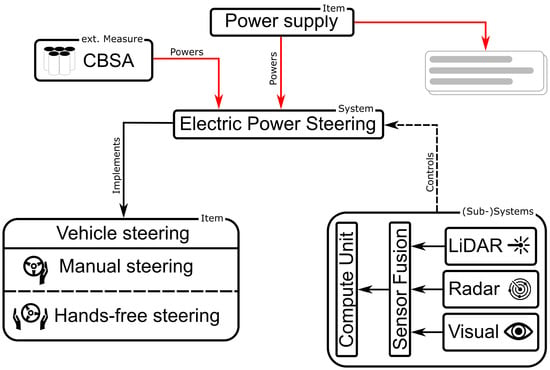
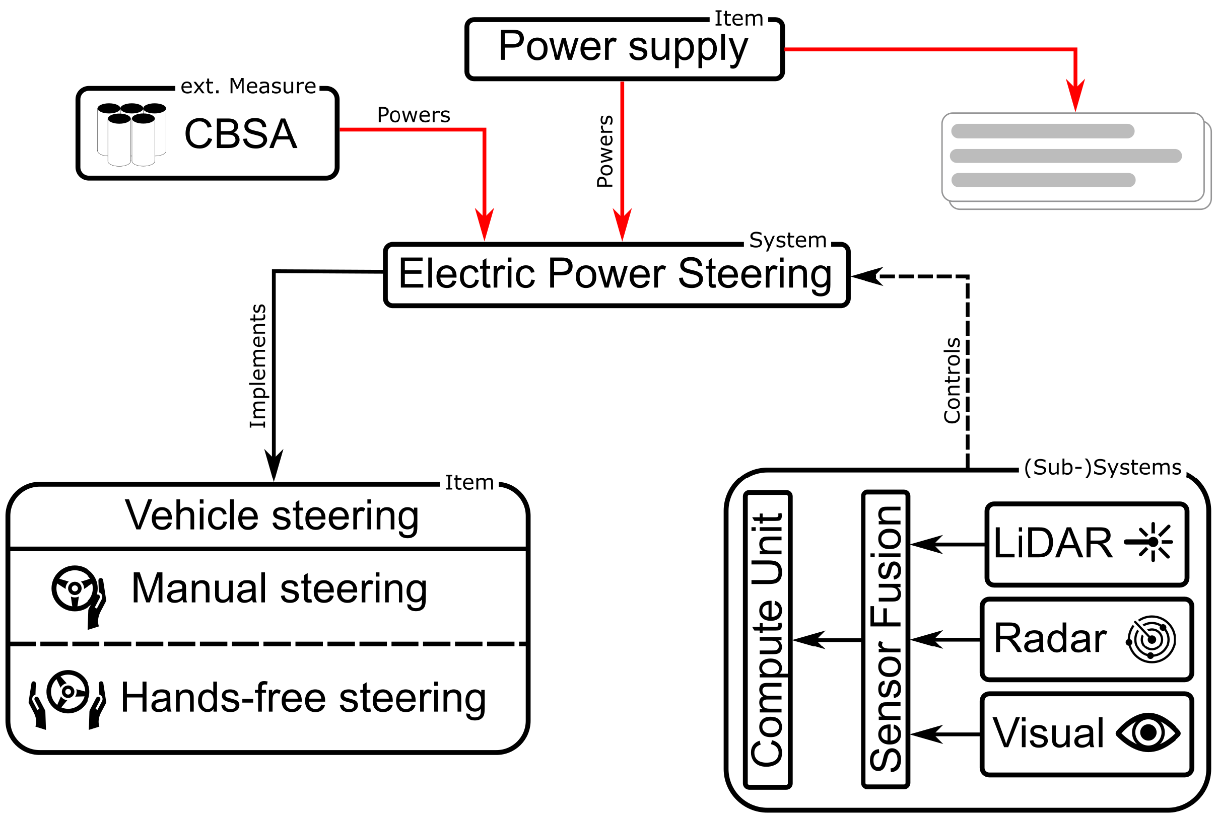
Figure 1 illustrates the item of vehicle steering together with corresponding subsystems and items. In addition to the EPS and its power supply, numerous auxiliary systems, such as cameras, radar, LiDAR sensors, and computing units are involved in the steering function, particularly in the context of automated driving. Furthermore, the CBSA module is already depicted, which is implemented as an external measure in this analysis. While the CBSA cannot be an item, because it does not implement a customer-observable vehicle function, the CBSA is an E/E system itself. For this reason, the CBSA must comply with ISO 26262. It can thus be treated as an item with safety goals derived from the steering system’s safety requirements. Following this logic, the following three main functions of the CBSA are defined:
Figure 1.
Implementation of the function vehicle steering by the Electric Power Steering, power supply, and numerous auxiliary items.
- 1.
- During undervoltage: Ensuring EPS functionality by supplying power until the fuse in the short circuit path trips.
- (a)
- Enabling the CBSA at <
- (b)
- Disabling the CBSA at >
- 2.
- During undervoltage: Opening recuperation path, to prevent feeding the short circuit.
- 3.
- During normal operation: Bidirectional conduction of supply current to EPS and recuperation current to power supplies.
Following the item definition, we conduct a simplified HARA and derive top-level safety goals. The vehicle function under consideration is a SAE Level 3 automated highway traffic jam assist. The loss of such a function could lead to low-speed (≤40 km/h) side or rear collisions with other passenger cars. According to [27], such collisions are rated with a severity classification of S2. A controllability of C3 is assigned because an SAE Level 3 system does not require and therefore cannot expect immediate driver intervention. The Exposure is rated as E4, as driving on a highway in traffic jam represents an everyday driving scenario. The FTTI is derived from the maximum duration of loss of steering assist, before the vehicle exits its lane and collides with another vehicle. This calculation assumes a maximum highway curvature and a velocity of ≤60 km/h. Based on this assumption, the FTTI is approximated to 20 ms. The top-level safety goal of the EPS is defined as the negation of the malfunction: “prevent sudden loss of steering assist.” This goal is allocated an ASIL-C rating and an FTTI of 20 ms. Furthermore, this high-level safety goal is decomposed into specific safety requirements for individual hardware (and software) components. ISO 26262 mandates specific development practices and Failure-in-Time (FiT) rates for these components based on their ASIL classification. Therefore, the development of systems with higher ASILs is typically more time-consuming and costly. The results of this exemplary HARA are presented in Table 1. Although the automated driving scenario defines the most stringent FTTI requirement, the corresponding EPS current demand is comparatively limited due to its moderate steering actuation and low lateral dynamics. Consequently, the subsequent verification distinguishes between this low-FTTI scenario and a dynamic evasive maneuver, which represents a high-current load case.
Table 1.
Assessment of the hazard: “sudden loss of steering assist”.
A key concept of ISO 26262 is the freedom from interference. ISO 26262 defines freedom from interference as the “absence of cascading failures between two or more elements that could lead to the violation of a safety requirement” [10]. Figure 1 illustrates that faults inside the EPS or the power supply can result in a sudden loss of steering assist. During automated driving, additional (sub-)systems such as ADAS sensors and compute units may cause similar hazards. If freedom from interference between two or more elements cannot be established, all involved elements must be developed according to the highest occurring ASIL. This requirement poses a challenge since in conventional E/E architectures, almost all systems are connected through a shared electrical network. This means a short circuit anywhere could lead to an undervoltage in the remaining electrical network, which in turn could result in a loss of steering assist. Such short circuits are typically mitigated by conventional melting fuses. However, the tripping time of some automotive fuses could exceed the FTTI of the previously explored ADAS steering system. Consequently, all connected systems that could violate the FTTI of the steering system during a short circuit would need to be developed in compliance with the same ASIL, even if they do not implement any safety-relevant function. From the perspective of cost and development effort, this approach is not feasible.
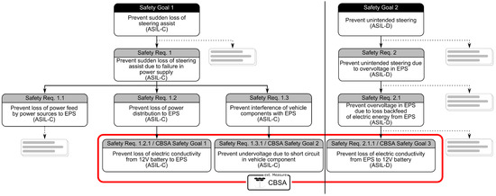
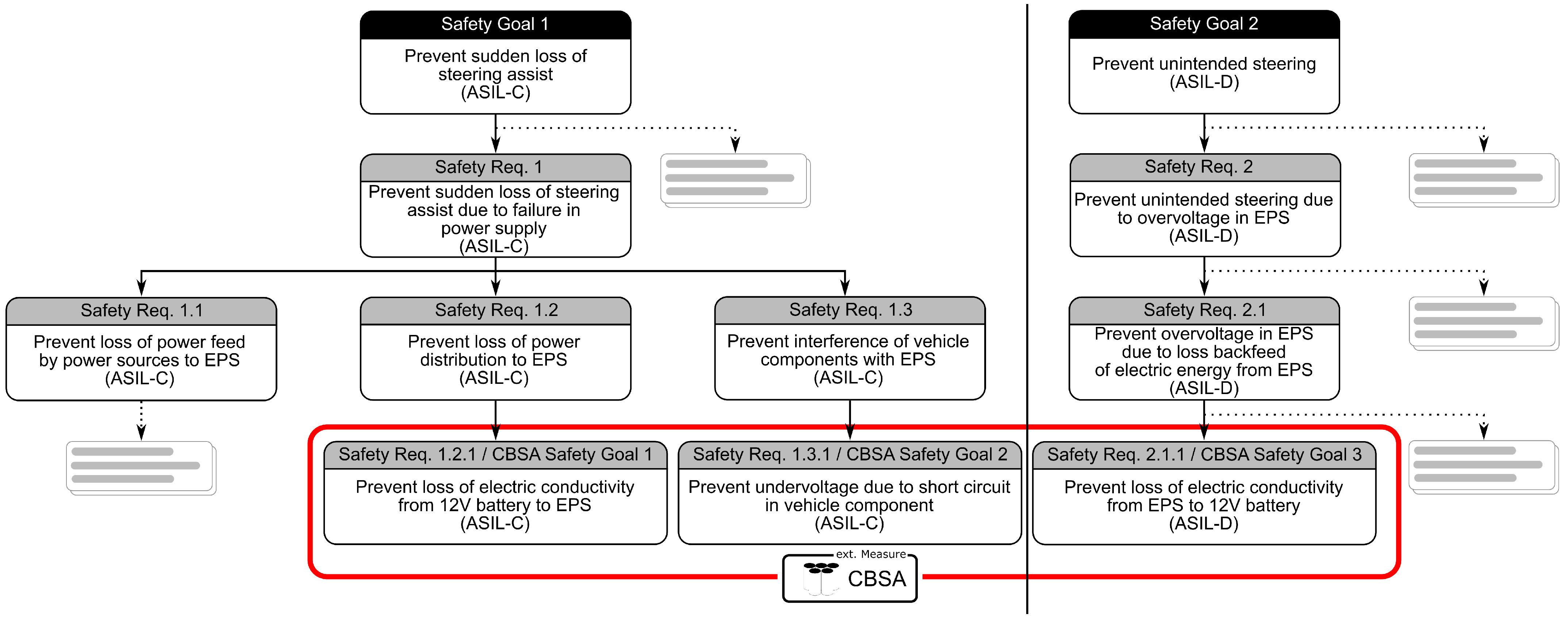
Figure 2 illustrates the two top-level safety goals of the steering system, from which the CBSA safety goals are derived. The steering system safety goal 1 was already derived in the preceding HARA and is consistent with the analysis presented in [18]. The fulfillment of safety requirement 1 ensures a stable power supply from the energy sources to the steering system. Safety requirements 1.1 and 1.2 demand reliable operation of the energy sources (12 V battery and alternator or DC/DC converter) and power distribution through the wiring harnesses. Safety requirement 1.3 ensures the previously introduced freedom from interference with respect to other vehicle components. Steering system safety goal 2 requires that recuperation currents can be fed back into the 12 V battery. When external forces act on the steering axis, the EPS operates in generator mode. If the resulting current cannot be fed back, the voltage at the EPS may increase and cause an overvoltage, potentially resulting in a steering lock. Depending on the vehicle context and the corresponding HARA, this hazard may result in an ASIL-D classification. Safety requirement 1.3.1 results in a corresponding CBSA safety goal because the CBSA acts as an external measure against interference from other vehicle components that the steering system cannot prevent. In contrast, safety requirements 1.2.1 and 2.1.1 result in CBSA safety goals because the CBSA is located between the steering system and the remaining power supply network. An internal CBSA fault could therefore interrupt either the conductive path from the power supplies to the EPS or the reverse conductive path from the EPS to the 12 V battery. Accordingly, the ASIL assigned to each CBSA safety goal is determined by the originating steering system safety requirement whose fulfillment may depend on, or be compromised by, the CBSA. This derivation constitutes safety requirement allocation across the system boundary rather than ASIL decomposition. In summary, the CBSA safety goals are defined as:
Figure 2.
Derivation of CBSA safety goals from steering system safety requirements.
- “Prevent undervoltage due to electrical fault in parallel vehicle component.”/ASIL-C
- “Prevent loss of electric conductivity from power supplies to EPS”/ASIL-C
- “Prevent loss of electric conductivity from EPS to 12 V battery during normal operation”/ASIL-D
4. Hardware Layout
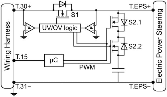
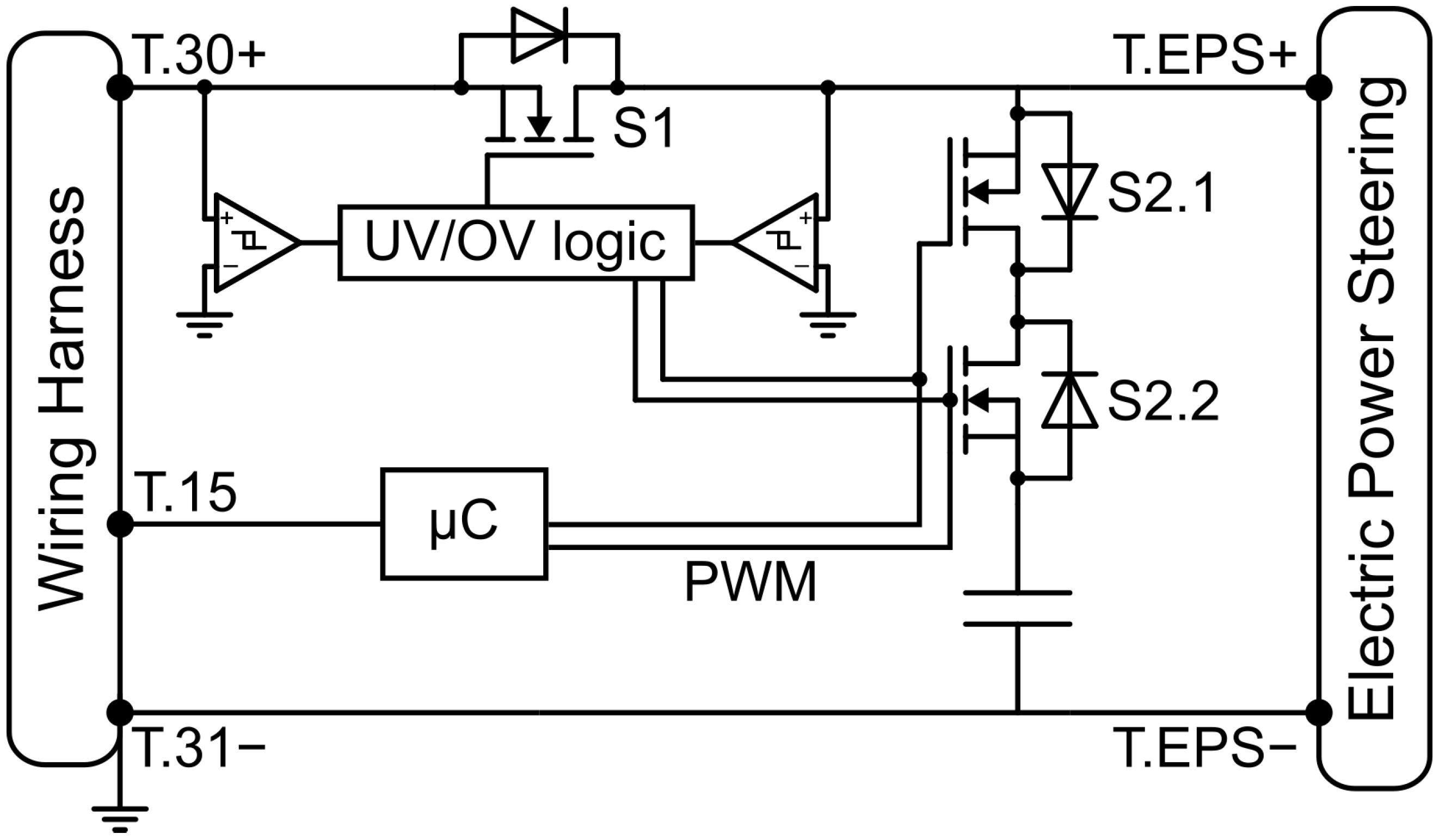
In this section, a possible hardware concept for implementing the CBSA is presented, derived from the requirements defined in the previous chapter. Figure 3 illustrates a simplified circuit diagram of the CBSA. On the left-hand side, the supply from the wiring harness side (Terminal 30) and the ground connection (Terminal 31) are depicted. On the right-hand side, the power input interface of the EPS (Terminal 30, EPS+) and the EPS ground connection (Terminal 31, EPS-) are shown. The upper main path acts as the main power supply during normal operation conditions. The n-channel MOSFET S1 is therefore closed in this operating state. To increase robustness and safety, the EPS can also be supplied through the intrinsic body diode in case S1 opens unintentionally. However, this leads to power dissipation and thus self-heating of the MOSFET. The n-MOSFETs S2.1 and S2.2 in the energy storage path are connected in a back-to-back configuration, enabling bidirectional current conduction. They are used to charge the capacitors at the beginning of the driving cycle and are otherwise open under normal operation.
Figure 3.
Basic CBSA topology to enable freedom from interference for the EPS.
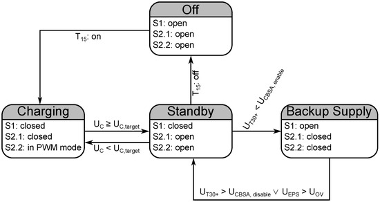
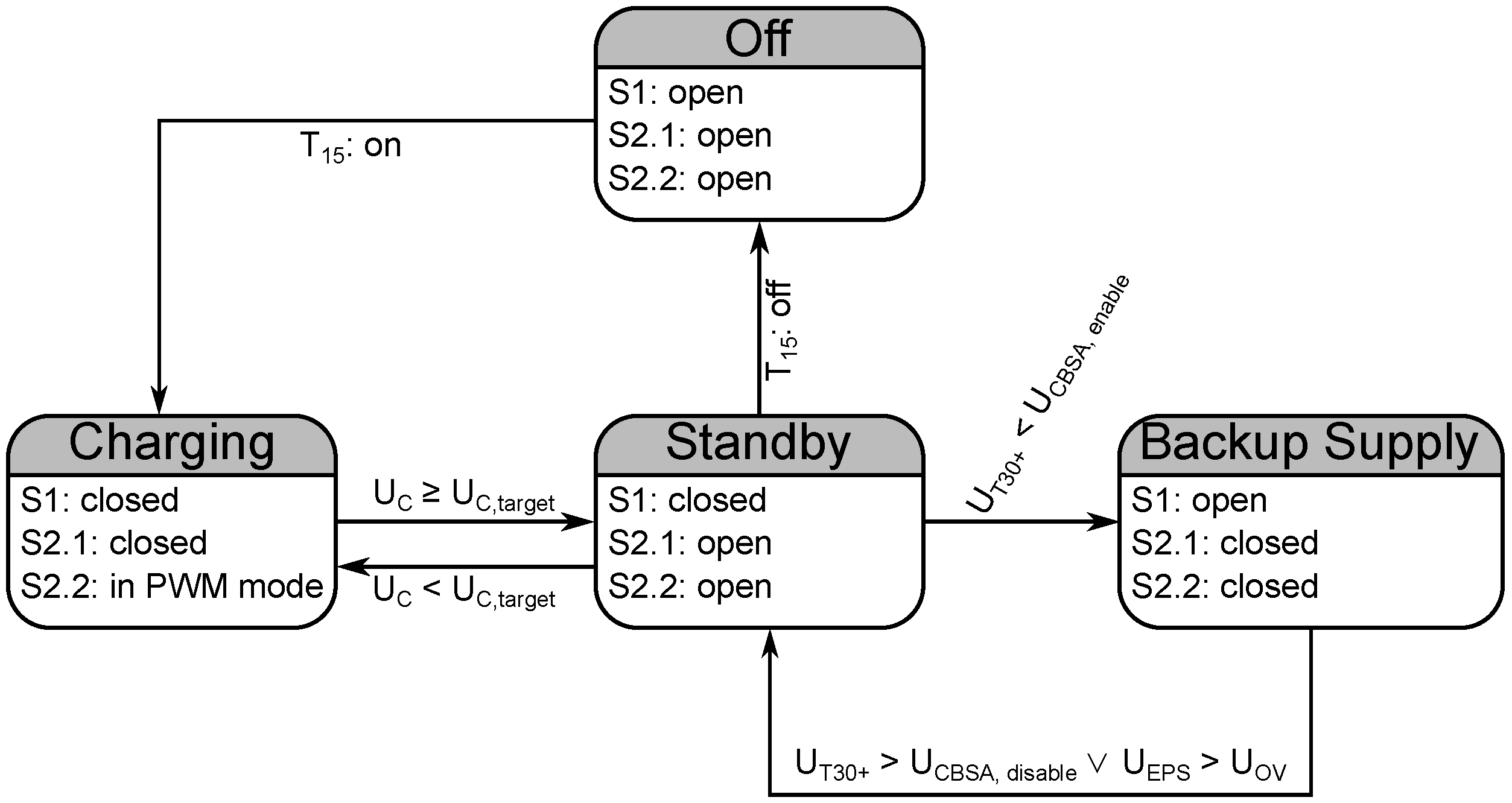
The MOSFET S2.2 is driven by a PWM generator of the microcontroller. This approach limits the initial inrush current, preventing high transient currents that could destabilize the vehicle’s power supply network. All MOSFETs are primarily controlled by the Undervoltage (UV)/Overvoltage (OV) logic unit. If the voltage at Terminal 30+ falls below the threshold voltage ( < ), this logic unit opens S1 and closes S2.1 and S2.2 to transition the power supply to the energy storage path. Figure 4 summarizes the concept-level operating states of the CBSA.
Figure 4.
Concept-level operating state machine of the CBSA.
After activation of Terminal 15, the capacitor bank is charged with a PWM-limited current. Once the target capacitor voltage is reached, the CBSA transitions to standby. If the voltage at Terminal 30+ falls below the threshold voltage ( < ) S1 opens and S2.1 and S2.2 close to transition the power supply to the backup supply path. During this operating state, the capacitors can temporarily absorb recuperation current generated by the EPS, to mitigate overvoltage on the EPS side. The CBSA returns to standby when the exceeds or when the EPS overvoltage threshold is exceeded. The separate enable and disable thresholds provide hysteresis. The transition to backup supply is subject to the design constraint < . To prevent unintended rapid switching (toggling) between states, Schmitt triggers are used for voltage monitoring on both the wiring harness and the EPS side. For simplicity, only one capacitor is depicted in the energy storage path. Since high-capacity cells are typically only rated for 2.7 to 3 V [29,30], a minimum of five capacitor cells are needed for a nominal voltage of 13–14 V. To charge the capacitors even further than nominal voltage, a DC/DC converter can be used. This increases the usable voltage range, but more series-connected capacitors may be needed, which in turn increases the equivalent series resistance and reduces total capacity of the capacitor bank. Both effects can be mitigated by adding additional capacitors in parallel, which, however, increases material costs and increases packaging requirements. Terminal 15 is connected to the microcontroller and provides the signal of the ignition status to the CBSA. This prevents the capacitors from charging while the vehicle is not in operation and therefore avoids unnecessary discharge of the 12 V battery.
5. Verification Results
This section presents initial verification activities and experimental results for a concept-level CBSA configuration. The objective is not to provide a final capacitor configuration or a complete validation of all CBSA safety goals and operating modes. Instead, the experiment investigates whether the CBSA can in principle support the EPS during a representative high-current undervoltage event under aged-cell and low-temperature boundary conditions. The design requirements are motivated by two complementary driving scenarios:
- Automated driving on a highway with limited lateral acceleration → FTTI-critical scenario.
- Manual driving during a highly dynamic evasive maneuver → high-current load verification scenario.
The experimental verification presented below focuses on the second scenario as the current-critical load case.
The electrical suitability of the capacitor bank depends on the EPS current profile, the usable voltage range, the capacitance, and the resistance of the capacitor bank. The currents, voltages, and trajectory of this maneuver were recorded using a test vehicle, equipped with extensive measurement technology. The entire maneuver lasts for approximately 5 s with a mean current flow of 12.7 A, but current peaks of up to 106 A for around 200 ms.
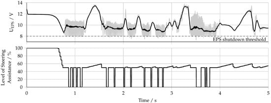
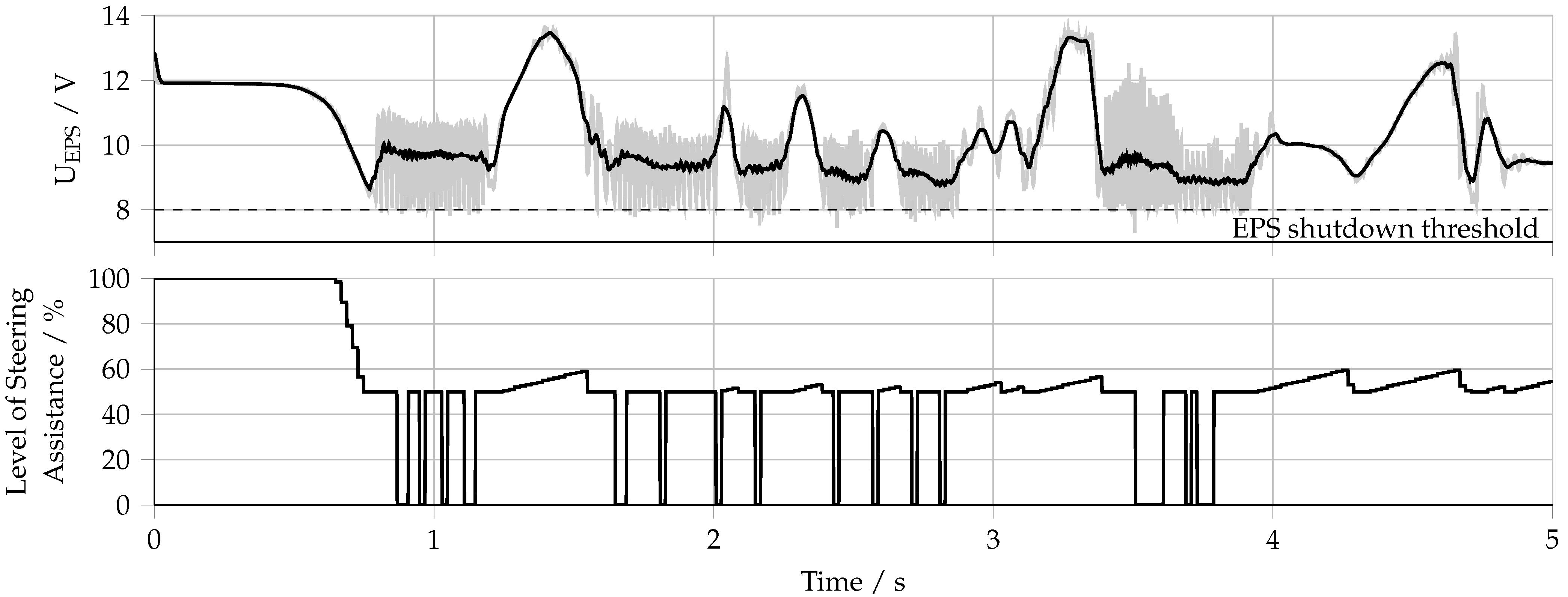
Using these measurements, the dynamic maneuver was recreated on a steering system HiL test bench to evaluate the CBSA configuration under reproducible conditions, with the option to inject an undervoltage fault. For the analysis below, 6 SECH 100 F/3 V (C18S-3Z0-0100, [31]) capacitors were used in a series configuration (6S1P), resulting in a total capacitance of 16.67 F. This configuration provides a maximum rated capacitor-bank voltage of 18 V, corresponding to a cell voltage of 2 V at the nominal power supply voltage of 12 V. The resulting voltage margin accommodates transient voltage spikes caused by steering recuperation or load-dump events in other vehicle systems. Furthermore, operating the cells below their rated voltage reduces voltage-related aging, as indicated in the datasheet [31]. The cells were subjected to the manufacturer-specified high-temperature DC-life condition of 1000 h at 85 °C and a constant voltage of 2.5 V per cell [31]. According to the manufacturer, the corresponding acceptance criteria after this test are a remaining capacitance above 70% of the rated value and an ESR below 200% of the rated value. This condition is used to represent aged capacitor cells and is not interpreted as an equivalent of a specific vehicle service life. Lastly, the HiL test bench was cooled to an ambient temperature of −20 °C to limit the performance of the capacitors even more. Figure 5 shows the EPS input voltage and the level of steering assistance provided by the EPS. The input voltage is quite noisy and therefore filtered through a moving average algorithm which outputs the mean value over a sliding window of 51 data points. Since this can distort the maxima and minima, the raw data are plotted additionally in gray. At the start of the experiment (t = 0 s), the external power supply drops to 0 V, to emulate a severe undervoltage event. The initial voltage of the capacitors (12 V) is therefore immediately established.
Figure 5.
EPS input voltage (top; grey: raw signal, black: mean signal, dashed: EPS shutdown threshold at 8 V) and level of steering assistance during dynamic evasive maneuver with injected undervoltage at t = 0 (bottom).
The capacitors do not discharge at a constant rate, as the current demand of the EPS is very dynamic. The voltage drops noticeably during periods of high current demand. This causes the steering system to reduce the level of steering assistance in order to limit the maximum possible currents. This is performed in discrete steps until the EPS shutdown voltage of 8 V is reached and the steering assistance falls to 0%. It can also be observed that the voltage repeatedly rises above the initial value of 12 V, reaching a maximum of almost 14 V. This behavior results from the restoring forces acting at the wheel, which induce a recuperation current as soon as the wheel steering angle decreases. This recuperation current charges the capacitors, since the recuperation path to the 12 V battery is open, to avoid feeding the short circuit instead of the EPS (see Section 3). The raw data show that the voltage drops below the shutdown threshold of 8 V multiple times (min. voltage = 7.3 V). As a consequence, the current flow stops and the voltage at the capacitors recovers. This process repeats, resulting in a toggling of the steering assistance, which is observable in the lower diagram. For the purpose of this initial verification, 100 ms is used as an external reference value, based on the considerations presented in [18]. Evaluation of the complete maneuver showed that the maximum continuous loss of steering assistance was 78 ms and therefore remained below this reference value. In additional vehicle tests using the same maneuver, an injected undervoltage fault, and an active CBSA, the temporary toggling of the steering assistance did not prevent the driver from successfully completing the evasive maneuver. A slight vibration of the steering wheel was observed. These initial results support the feasibility of the CBSA concept under the investigated boundary conditions, including aged cells and low ambient temperature. However, the presented results do not constitute a complete validation of freedom from interference according to ISO 26262. Such a validation would require additional fault-injection tests, verification of the isolation behavior and the response time.
6. Conclusions and Outlook
In the context of future steering systems with a higher ASIL classification and decreasing FTTI, faults in parallel loads represent a potential risk for the freedom from interference. Depending on the driving situation, a resulting loss of steering assist could have severe consequences. This work presented the concept of a capacitor-based safety adapter, which is located between the safety-relevant system and the remaining wiring harness. In case of undervoltage, the system to be protected is supplied by the CBSA and isolated from the faulty wiring harness for a limited amount of time. Compared to selected approaches discussed in the literature, the CBSA concept may offer advantages with respect to development effort and integration aspects. As it requires only minimal wiring and software modifications, the CBSA is particularly suitable to be retrofitted into existing platforms. The CBSA safety goals were derived from steering-system safety requirements that either depend on the CBSA as an external measure or could be violated by an internal CBSA fault. The basic principle of the CBSA was explained using a minimal exemplary circuit diagram. Future work will analyze this concept in more detail from the perspective of functional safety, e.g., via a Fault Tree Analysis and Failure Modes, Effects, and Diagnostic Analysis. Furthermore, initial HiL-verification results indicate that the CBSA can support the EPS during a representative high-current undervoltage scenario, even when using aged capacitors at low ambient temperature. However, future work is required to verify the fulfillment of all overarching safety goals under additional high- and low-FTTI driving scenarios. Furthermore, it is important to determine the economic break-even point between the deployment of additional CBSAs for other safety-relevant systems and implementing a centralized approach.
Author Contributions
Conceptualization, T.K., E.S. and J.P.; methodology, T.K. and E.S.; validation, T.K. and E.S.; investigation, T.K. and E.S.; writing—original draft preparation, T.K. and E.S.; writing—review and editing, T.K. and J.P.; visualization, T.K.; supervision, J.P.; project administration, T.K. All authors have read and agreed to the published version of the manuscript.
Funding
This research received no external funding.
Data Availability Statement
The datasets presented in this article are not readily available because they are proprietary and confidential data of Volkswagen AG. Requests to access the datasets should be directed to the corresponding author and are subject to approval by Volkswagen AG.
Conflicts of Interest
Tim Klatt and Emir Sagdani were employed by the company Volkswagen AG. The remaining author declares that the research was conducted in the absence of any commercial or financial relationships that could be construed as a potential conflict of interest.
References
- Zerfowski, D.; Lock, A. Functional architecture and E/E-Architecture—A challenge for the automotive industry. In 19. Internationales Stuttgarter Symposium; Bargende, M., Reuss, H.C., Wagner, A., Wiedemann, J., Eds.; Proceedings; Springer: Wiesbaden, Germany, 2019; pp. 909–920. [Google Scholar] [CrossRef] [Scilit]
- Hua, L.; Antona-Makoshi, J.; Neurauter, L. Status and Challenges of Level 3 Automated Driving Systems. Available online: https://vtechworks.lib.vt.edu/server/api/core/bitstreams/6346e9ab-6644-4b79-9dc0-e9527863ab0f/content (accessed on 6 June 2025).
- Statista GmbH. Entwicklung des Leergewichts von Neuwagen in Deutschland von 2005 bis 2024. 2025. Available online: https://de.statista.com/statistik/daten/studie/12944/umfrage/entwicklung-des-leergewichts-von-neuwagen/ (accessed on 6 June 2025).
- Statista GmbH. SUVs—Worldwide. 2025. Available online: https://www.statista.com/outlook/mmo/passenger-cars/suvs/worldwide (accessed on 10 July 2025).
- Mortazavizadeh, S.A.; Ghaderi, A.; Ebrahimi, M.; Hajian, M. Recent Developments in the Vehicle Steer-by-Wire System. IEEE Trans. Transp. Electrif. 2020, 6, 1226–1235. [Google Scholar] [CrossRef] [Scilit]
- Huang, C.; Li, L. Architectural design and analysis of a steer-by-wire system in view of functional safety concept. Reliab. Eng. Syst. Saf. 2020, 198, 106822. [Google Scholar] [CrossRef] [Scilit]
- Stolte, T.; Ackermann, S.; Graubohm, R.; Jatzkowski, I.; Klamann, B.; Winner, H.; Maurer, M. Taxonomy to Unify Fault Tolerance Regimes for Automotive Systems: Defining Fail-Operational, Fail-Degraded, and Fail-Safe. IEEE Trans. Intell. Veh. 2022, 7, 251–262. [Google Scholar] [CrossRef] [Scilit]
- SAE International. Taxonomy and Definitions for Terms Related to Driving Automation Systems for On-Road Motor Vehicles; SAE International: Warrendale, PA, USA, 2014. [Google Scholar] [CrossRef] [Scilit]
- Sari, B. Fail-Operational Safety Architecture for ADAS/AD Systems and a Model-Driven Approach for Dependent Failure Analysis. Doctoral Thesis, University of Stuttgart, Stuttgart, Germany, 2020. [Google Scholar] [CrossRef] [Scilit]
- ISO 26262:2018; Road Vehicles—Functional Safety. International Organization for Standardization: Geneva, Switzerland, 2018. Available online: https://www.iso.org/standard/68383.html (accessed on 17 June 2025).
- Koehler, A.; Bertsche, B. An approach of fail operational power supply for next generation vehicle powernet architectures. In Proceedings of the 30th European Safety and Reliability Conference and the 15th Probabilistic Safety Assessment and Management Conference (ESREL-PSAM), Venice, Italy, 1–5 November 2020; pp. 60–67. [Google Scholar] [CrossRef] [Scilit]
- Verband der Automobilindustrie e.V. VDA Empfehlung 450: Energiebordnetzentwicklung fuer Automatisiertes Fahren im Rahmen der ISO 26262. 2023. Available online: https://webshop.vda.de/VDA/en/vda-450-042023-en (accessed on 12 June 2025).
- Littelfuse, Inc. MAXI+ Blade Fuses—0899 Series; Technical Report 0899; Littelfuse: Chicago, IL, USA, 2024; Available online: https://www.littelfuse.com/assetdocs/littelfusedatasheet0899maxirestyling?assetguid=4c70ad1d-4dea-41de-9fa9-02a57483e992 (accessed on 10 July 2025).
- Mayer, C.; Baumann, M.; Eisenmann, B.; Herzog, H.G. A Review of Electronic Fuses: Challenges and Opportunities for Future Vehicular Power Systems. IEEE Trans. Transp. Electrif. 2025, 11, 8548–8560. [Google Scholar] [CrossRef] [Scilit]
- Panguloori, R. Basics of eFuses. 2016. Revised April 2018. Available online: https://www.ti.com/lit/an/slva862a/slva862a.pdf (accessed on 10 July 2025).
- Gerten, M.; Frei, S.; Kiffmeier, M.; Bettgens, O. Influence of Electronic and Melting Fuses on the Transient Behavior of Automotive Power Supply Systems. IEEE Trans. Transp. Electrif. 2024, 10, 4065–4073. [Google Scholar] [CrossRef] [Scilit]
- Gerten, M.; Frei, S.; Kiffmeier, M.; Bettgens, O. Voltage Stability of Automotive Power Supplies During Tripping Events of Melting and Electronic Fuses. In Proceedings of the 2022 IEEE 95th Vehicular Technology Conference: (VTC2022-Spring); IEEE: New York, NY, USA, 2022; pp. 1–6. [Google Scholar] [CrossRef] [Scilit]
- Kilian, P.; Kohler, A.; van Bergen, P.; Gebauer, C.; Pfeufer, B.; Koller, O.; Bertsche, B. Principle Guidelines for Safe Power Supply Systems Development. IEEE Access 2021, 9, 107751–107766. [Google Scholar] [CrossRef] [Scilit]
- Kilian, P.; van Bergen, P.; Koller, O.; Gebauer, C.; Heidinger, F.; Dazer, M. Emergency Operation in the Power Supply Domain Focusing on Warm Redundancy. IEEE Access 2022, 10, 123474–123488. [Google Scholar] [CrossRef] [Scilit]
- Kilian, P.; Koller, O.; van Bergen, P.; Gebauer, C.; Dazer, M. Safety-Related Availability in the Power Supply Domain. IEEE Access 2022, 10, 47869–47880. [Google Scholar] [CrossRef] [Scilit]
- Kilian, P.; Koller, O.; van Bergen, P.; Gebauer, C.; Heidinger, F.; Dazer, M. Emergency Operation in the Power Supply Domain According to ISO 26262. IEEE Access 2022, 10, 47557–47569. [Google Scholar] [CrossRef] [Scilit]
- Letor, R.; Crisafulli, R. Smart Power devices and new electronic fuses compliant with new E/E architecture for autonomous driving. In Proceedings of the 2019 AEIT International Conference of Electrical and Electronic Technologies for Automotive (AEIT AUTOMOTIVE); IEEE: New York, NY, USA, 2019; pp. 1–6. [Google Scholar] [CrossRef] [Scilit]
- Schipperges, F.; Luo, F.J.; Pazmany, J.G.; Baeker, B. Reliability Assessment of a Redundant 12V On-Board Power Supply Using Solid-State Safety Relays. 2019. Available online: https://ieeexplore.ieee.org/document/8727846 (accessed on 21 July 2025).
- Liang, X.; Yang, G.; Han, S.; Deng, Z. Functional Safety Design And Verification Of Vehicle Powernet Based On L3 Automatic Driving. In Proceedings of the 2024 International Conference on Autonomous Driving and Intelligent Sensing Technology; Association for Computing Machinery: New York, NY, USA, 2024; pp. 17–21. [Google Scholar] [CrossRef] [Scilit]
- Gorelik, K.; Kilic, A.; Obermaisser, R. Connected Energy Management System for Automated Electric Vehicles With Fail-Operational Powertrain and Powernet. IEEE Trans. Veh. Technol. 2019, 68, 9588–9603. [Google Scholar] [CrossRef] [Scilit]
- Schumi, S. Energy and Supply Concepts for Automated Driving. In Proceedings of the 2018 IEEE International Conference on Electrical Systems for Aircraft, Railway, Ship Propulsion and Road Vehicles & International Transportation Electrification Conference (ESARS-ITEC); IEEE: New York, NY, USA, 2018; pp. 1–5. [Google Scholar] [CrossRef] [Scilit]
- J2980_202310; Considerations for ISO 26262 ASIL Hazard Classification. Society of Automotive Engineers: Warrendale, PA, USA, 2023. [CrossRef] [Scilit] [PubMed]
- Verband der Automobilindustrie e.V. VDA Empfehlung 702: Situationskatalog E-Parameter nach ISO 26262-3:2018. 2023. Available online: https://webshop.vda.de/VDA/de/vda-702-062023-v2 (accessed on 9 July 2025).
- Maxwell Technologies Inc. 3.0V 100F ULTRACAPACITOR CELL: Datasheet. Available online: https://maxwell.com/wp-content/uploads/2021/08/3003111-EN.1_3V-100F-Datasheet.pdf (accessed on 29 July 2025).
- Eaton Electronics Division Inc. TVA Supercapacitors: Automotive Grade Cylindrical Cells. Available online: https://www.eaton.com/content/dam/eaton/products/electronic-components/resources/data-sheet/eaton-tva-automotive-supercapacitor-cylindrical-cell-data-sheet-elx1087-en.pdf (accessed on 29 July 2025).
- SECH SA. Product Datasheet—Small Cell Ultracapacitor. 2025. Available online: https://www.sechsa.com/wp-content/uploads/Small-Ultracapacitor-Cells-China-3.3F-100F.pdf (accessed on 29 July 2025).

Disclaimer/Publisher’s Note: The statements, opinions and data contained in all publications are solely those of the individual author(s) and contributor(s) and not of MDPI and/or the editor(s). MDPI and/or the editor(s) disclaim responsibility for any injury to people or property resulting from any ideas, methods, instructions or products referred to in the content. |
© 2026 by the authors. Licensee MDPI, Basel, Switzerland. This article is an open access article distributed under the terms and conditions of the Creative Commons Attribution (CC BY) license.