
Research on the Active Suspension Control Strategy of Multi-Axle Emergency Rescue Vehicles Based on the Inverse Position Solution of a Parallel Mechanism

 ,
, 
Abstract
1. Introduction
- (1)
- To tackle the problem that the control complexity of the active suspension in multi-axle vehicles scales linearly with the number of actuators, by dividing the active suspension actuator hydraulic cylinders into three groups and interconnecting the hydraulic cylinders within each group, the multi-point support for the vehicle body has been successfully transformed into the virtual three-point support for the vehicle body. This conversion significantly reduces the workload of control, shifting from the independent control of each hydraulic cylinder to the integrated control of the hydraulic cylinder group. The calculation of the expansion and contraction amounts of multiple actuators in the past control strategy has been transformed into the calculation of only three virtual actuators’ expansion and contraction amounts, greatly improving the calculation efficiency and significantly enhancing the control efficiency. The ASCS-IPSPM also has broad applicability, not limited by the number of active suspension actuators, and can achieve efficient control through reasonable grouping.
- (2)
- The interconnected design between the hydraulic cylinders within the group enables the load self-balancing and self-adjustment functions of the active suspension system for multi-axle vehicles. Without relying on external control, the load balance of the suspension within the group can be maintained and effectively controlled, significantly reducing the difficulty of control while improving the stability and reliability of the system.
- (3)
- This article innovatively proposes a method for abstract complex multi-axle vehicle chassis as a 3-DOF parallel mechanism. By utilizing the inverse position solution of the parallel mechanism, the control quantities of actuators are calculated, achieving the efficient decoupling of complex active suspension systems and the precise control of vehicle attitude. This innovative approach provides a new perspective and tool for research on active suspension control methods in multi-axle vehicles.
2. Active Suspension Control Strategy Based on the Inverse Kinematics of a Parallel Mechanism
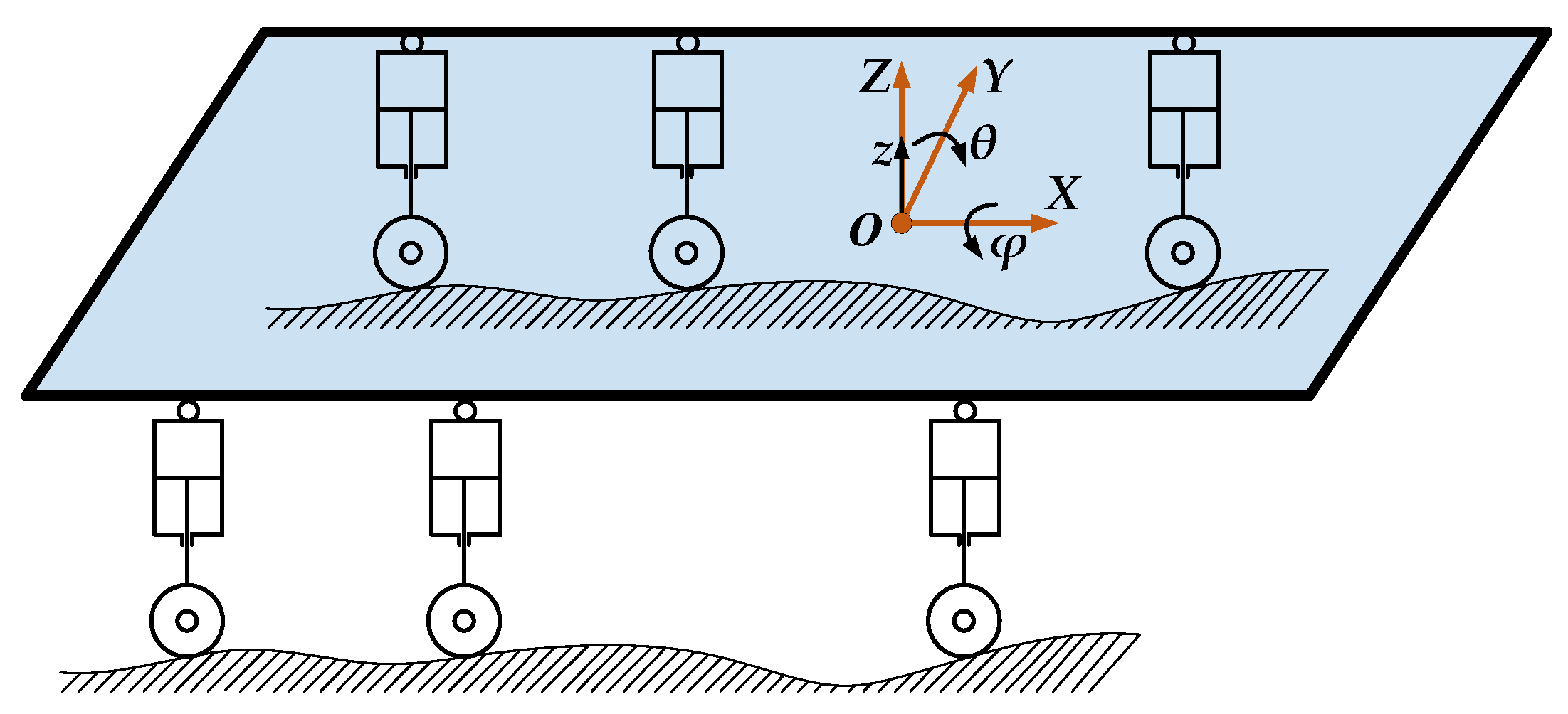
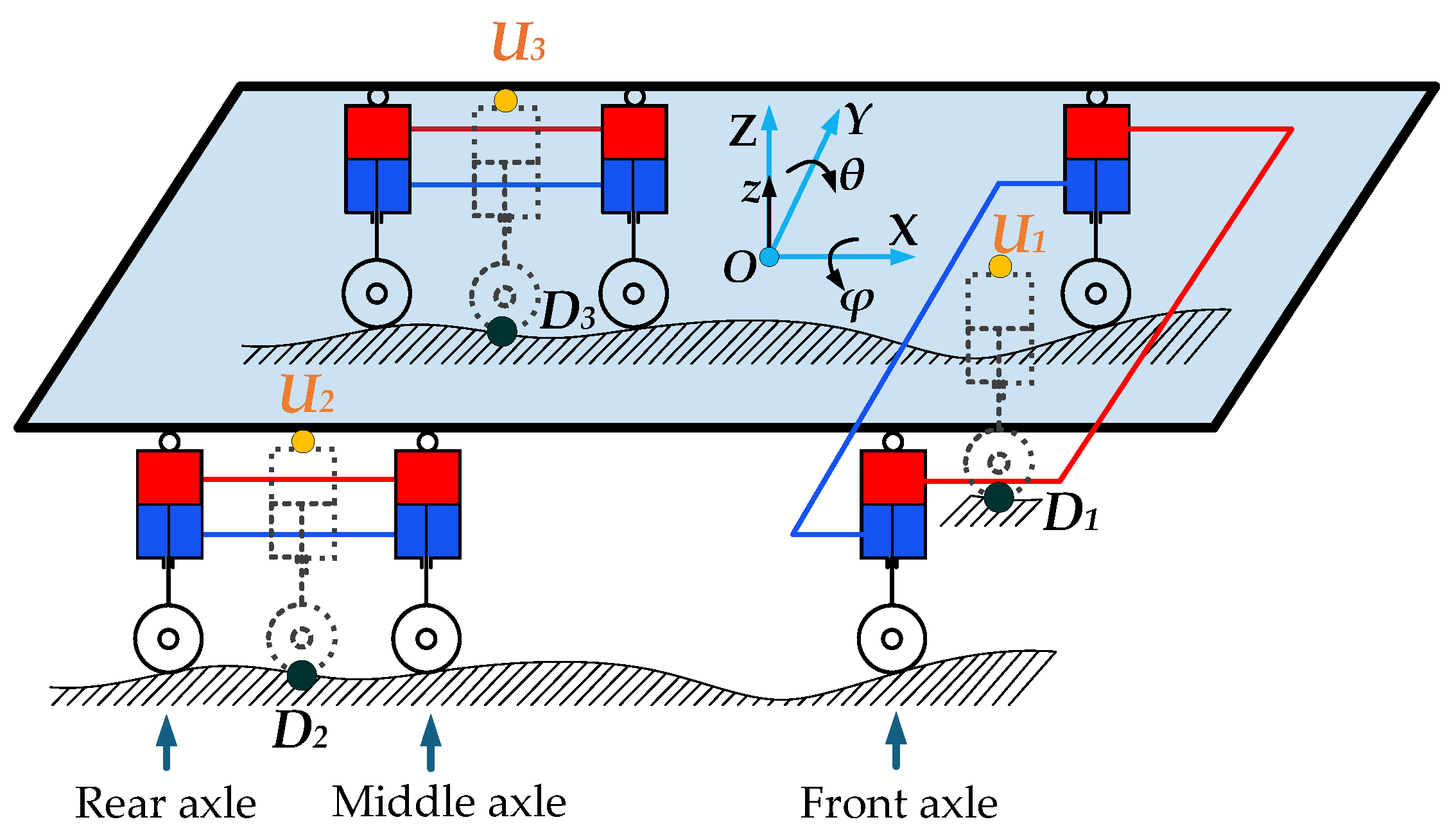
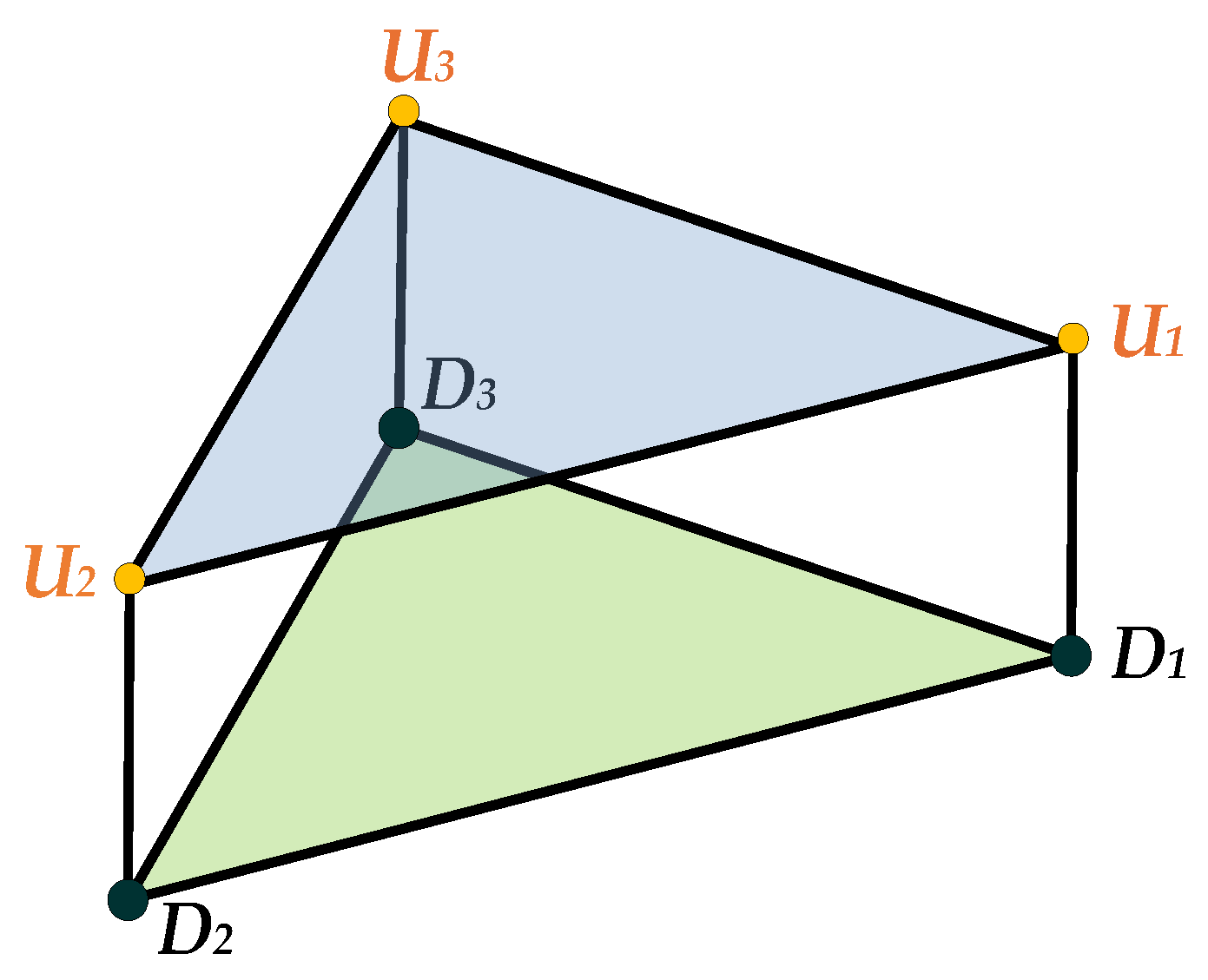
2.1. Construction of an Equivalent 3-DOF Parallel Mechanism for Three-Axis Vehicles
2.2. Inverse Position Solution of the Equivalent 3-DOF Parallel Mechanism
2.3. Principle of the ASCS-IPSPM
- (1)
- At the initial time t0, the vertical displacement, roll angle, and pitch angle measured by sensors at the point OS are , , and , respectively. After coordinate transformation, the vertical displacement, roll angle, and pitch angle at the center point OU are , , and , respectively, which are the input signals in Figure 9. At the current time t, the vehicle is driving on an unstructured road. At this time, the vertical displacement, roll angle, and pitch angle measured by sensors at the point OS are , , and , respectively. The vertical displacement, roll angle, and pitch angle at the point OU are , , and , respectively, which are the output signals in Figure 9.
- (2)
- The attitude variation of the moving platform at time t is , , and relative to that at time t0.
- (3)
- Taking , , and as the relative attitude correction of the equivalent 3-DOF parallel mechanism moving platform of the three-axis vehicle, and replacing the attitude parameters , , and in Equations (20)–(22) with , , and respectively, and then combining with Equation (23), the inverse position solution L1, L2, and L3 directly mapped to the sensors measurement can be derived, as shown in Equations (24)–(26). Equations (24)–(26) are the expansion amount of each equivalent driving rod. Then, L1, L2, and L3 are used as displacement commands to perform displacement servo control on the equivalent drive rods U1D1, U2D2, and U3D3 (the control of the equivalent drive rod is achieved by controlling the average displacement of the two suspension actuating hydraulic cylinders in each group). The control target of the vehicle body attitude can be realized, so the vertical displacement, pitch angle, and roll angle of the vehicle body can be kept as stable as possible. This part is the position inverse solution module in Figure 9.
3. Construction of the Three-Axle Vehicle Experimental Platform and Experiments
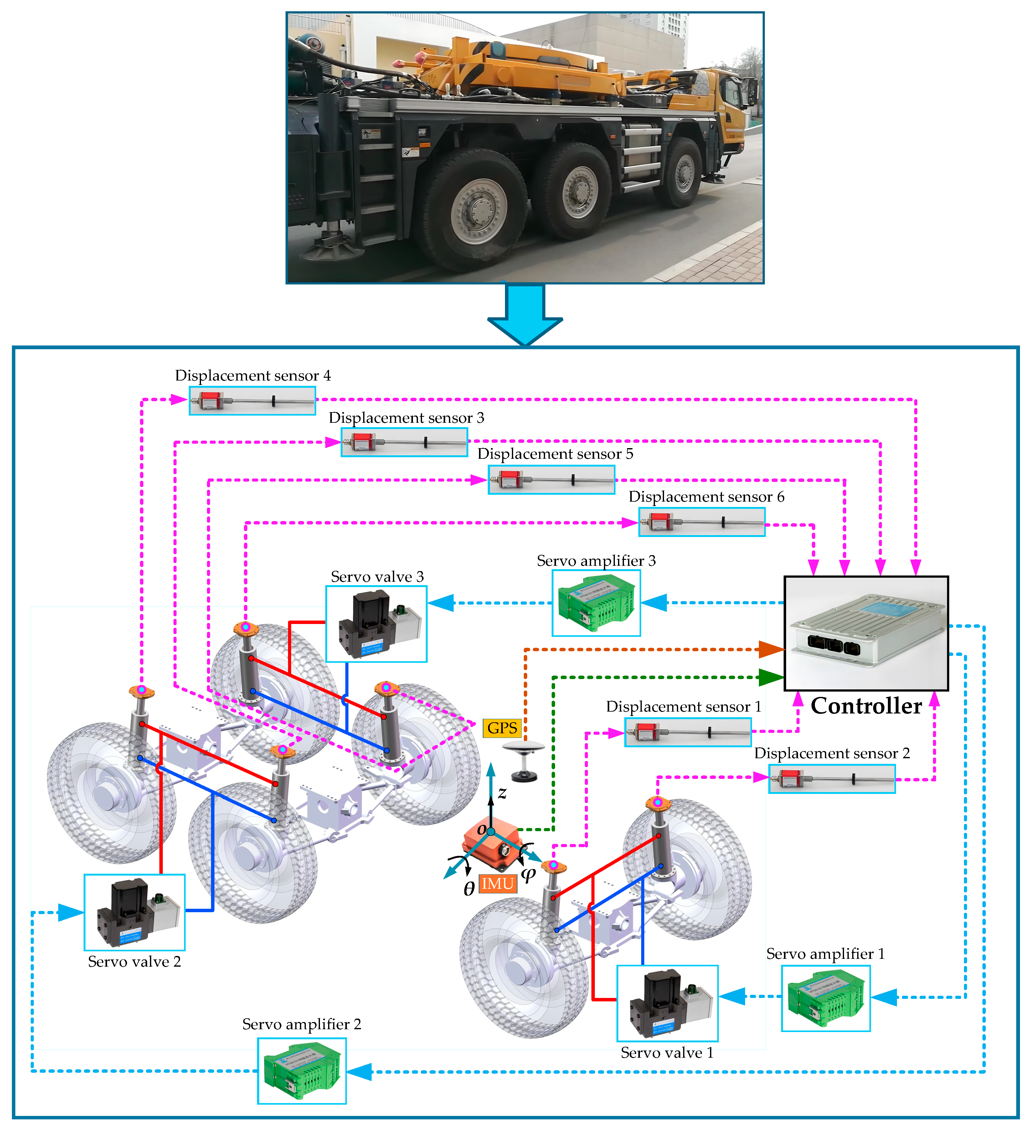
3.1. Construction of the Three-Axle Vehicle Experimental Platform
3.2. Road Experiments
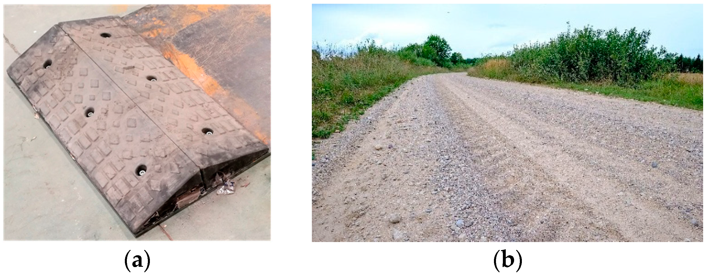
3.2.1. Pulse Road Experiment
- Experimental scheme
- (1)
- The experimental scheme of bilateral triangular deceleration strips
- (2)
- The experimental scheme of the unilateral triangular deceleration strip
- 2.
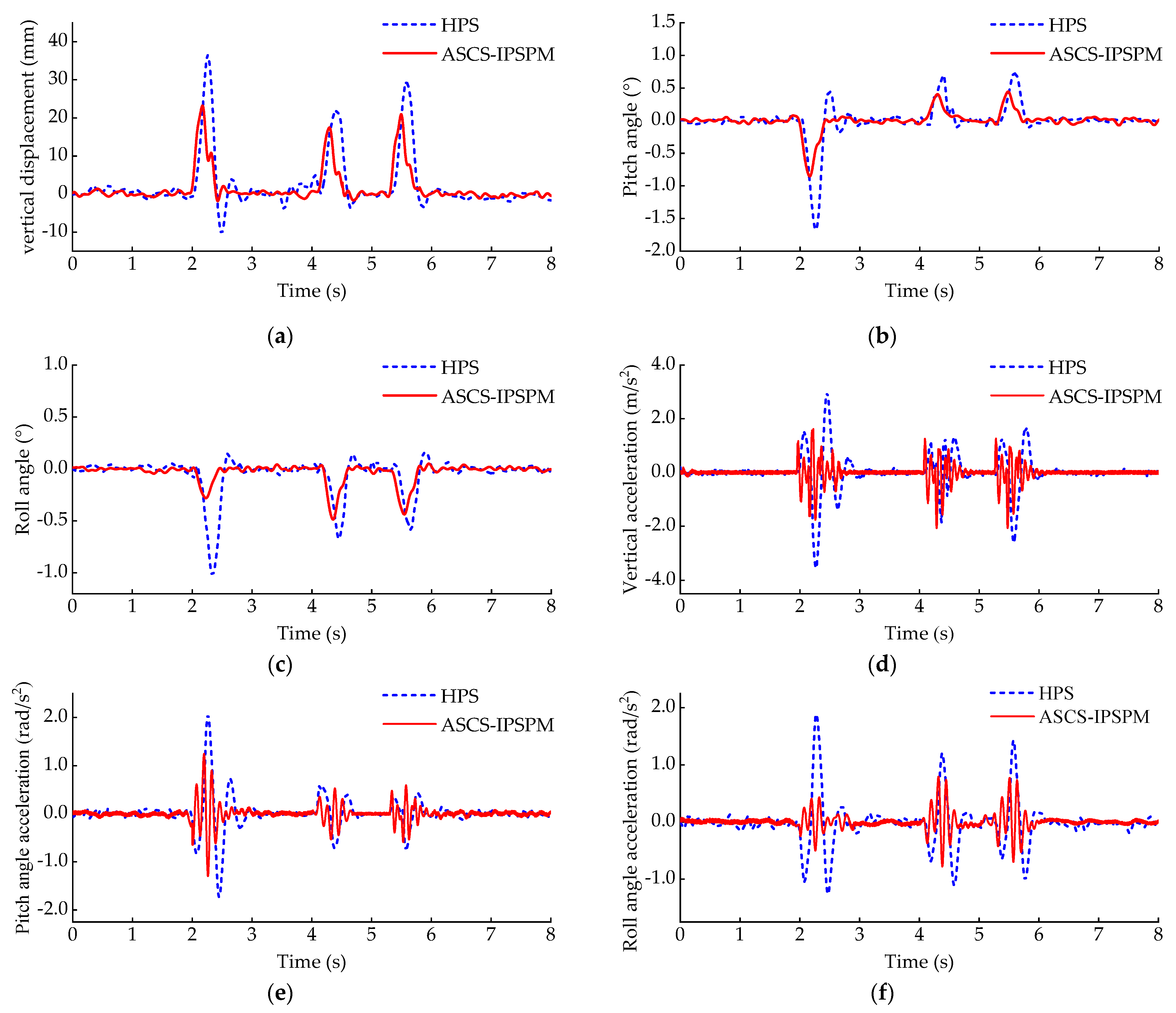
- Experimental results and analysis
3.2.2. Gravel Pavement Experiment
- Experimental scheme
- 2.
- Experimental results and analysis
4. Discussion and Conclusions
Author Contributions
Funding
Data Availability Statement
Conflicts of Interest
Abbreviations
| ASCS-IPSPM | Active Suspension Control Strategy Based on Inverse Position Solution of Parallel Mechanism |
| HPS | Hydro-pneumatic Suspension |
| IMU | Inertial Measurement Unit |
| RMS | Root Mean Square |
References
- Chen, T.; Cai, Y.F.; Chen, L.; Xu, X. Trajectory planning method of emergency rescue vehicle based on fourth-order bezier curve. Chin. J. Mech. Eng. 2025, 61, 198–209. [Google Scholar]
- Xu, F.X. Research on the Control Strategies and Experiments for Multi-Mode Steer-by-Wire System of Emergency Rescue Vehicles. Ph.D. Thesis, Jilin University, Changchun, China, 2020. [Google Scholar]
- Zhou, C. Research on the Control Strategies for Hydro-Pneumatic Suspension and Active Front Steering Systems of Emergency Rescue Vehicles. Ph.D. Thesis, Jilin University, Changchun, China, 2021. [Google Scholar]
- Jaikumar, M.; Samuel, R.T.; Samy, S.A.; Hariram, V. Experimental investigation on improving the comfort of the vehicle based on damping characteristics of passive suspension system using quarter car model. Int. J. Veh. Struct. Syst. 2022, 14, 472–476. [Google Scholar] [CrossRef]
- Kumar, S.; Amit, M.; Raghuvir, K. Optimization of nonlinear passive suspension system to minimize road damage for heavy goods vehicle. Int. J. Acoust. Vib. 2021, 26, 56–63. [Google Scholar] [CrossRef]
- Wang, J.; Lv, K.; Wang, H. Nonlinear dynamics and control of connected hydro-pneumatic suspension with fractional order. Int. J. Nonlinear Mech. 2023, 157, 104516. [Google Scholar] [CrossRef]
- Viadero-Monasterio, F.; Meléndez-Useros, M.; Jiménez-Salas, M.; Boada, B.L. Robust static output feedback control of a semi-active vehicle suspension based on magnetorheological dampers. Appl. Sci. 2024, 14, 10336. [Google Scholar] [CrossRef]
- Li, M.; Xu, J.; Wang, Z.; Liu, S. Optimization of the semi-active-suspension control of BP neural network PID based on the sparrow search algorithm. Sensors 2024, 24, 1757. [Google Scholar] [CrossRef]
- Zhang, X.; Zhang, Y.; Zhao, Y.; Nie, J. A multi-hook control strategy for a semi-active device combining an adjustable inerter and damper. Actuators 2022, 11, 297. [Google Scholar] [CrossRef]
- Habibi, H. Control of Active Suspension Systems Based on Mechanical Wave Concepts. Actuators 2025, 14, 230. [Google Scholar] [CrossRef]
- Wang, G.; Deng, J.; Zhou, T.; Liu, S. Reinforcement Learning-Based Vibration Control for Half-Car Active Suspension Considering Unknown Dynamics and Preset Convergence Rate. Processes 2024, 12, 1591. [Google Scholar] [CrossRef]
- Meng, X.; Kong, L.; Ding, R.; Liu, W.; Wang, R. Research on active suspension control based on vehicle speed control under transient pavement excitation. World Electr. Veh. J. 2025, 16, 232. [Google Scholar] [CrossRef]
- Gysen, B.L.J.; Janssen, J.L.G.; Paulides, J.J.H.; Lomonova, E.A. Design aspects of an active electromagnetic suspension system for automotive applications. IEEE Trans. Ind. Appl. 2009, 45, 1589–1597. [Google Scholar] [CrossRef]
- Yu, M.; Evangelou, S.A.; Dini, D. Advances in active suspension systems for road vehicles. Engineering 2024, 33, 160–177. [Google Scholar] [CrossRef]
- Liu, J.; Li, X.; Wang, Z.; Zhang, Y. Modelling and experimental study on active energy-regenerative suspension structure with variable universe fuzzy pd control. Shock Vib. 2016, 2016, 6170275. [Google Scholar] [CrossRef]
- Jeong, Y.; Yim, S. Design of Active suspension controllers for 8× 8 armored combat vehicles. Machines 2024, 12, 931. [Google Scholar] [CrossRef]
- Zhang, Z.; Guan, J.; Cao, L.; Li, W. Research on suspension travel tracking preview control algorithm of active suspension for multi-axle vehicle. In Proceedings of the Ninth International Conference on Mechanical Engineering, Materials, and Automation Technology (MMEAT 2023), Dalian, China, 9–11 June 2023. [Google Scholar]
- Wang, W.; Liu, S.; Zhao, D. A low-complexity fixed-time prescribed performance control for uncertain full-vehicle active suspensions with hydraulic actuators. Int. J. Control 2024, 8, 1272–1283. [Google Scholar] [CrossRef]
- Khan, L.; Qamar, S.; Khan, U. Adaptive PID control scheme for full car suspension control. J. Chin. Inst. Eng. 2016, 39, 169–185. [Google Scholar] [CrossRef]
- Kumar, S.; Medhavi, A.; Kumar, R.; Mall, P.K. Modeling and analysis of active full vehicle suspension model optimized using the advanced fuzzy logic controller. Int. J. Acoust. Vib 2022, 27, 26–36. [Google Scholar]
- Zhang, J.; Li, K.; Li, Y. Neuro-adaptive optimized control for full active suspension systems with full state constraints. Neurocomputing 2021, 458, 478–489. [Google Scholar] [CrossRef]
- Na, J.; Huang, Y.; Pei, Q.; Wu, X.; Gao, G.; Li, G. Active suspension control of full-car systems without function approximation. IEEE/ASME Trans. Mechatron. 2019, 25, 779–791. [Google Scholar] [CrossRef]
- Lin, Y.C.; Nguyen, H.L.T.; Yang, J.F.; Chiou, H.J. A reinforcement learning backstepping-based control design for a full vehicle active Macpherson suspension system. IET Control Theory Appl. 2022, 16, 1417–1430. [Google Scholar] [CrossRef]
- Kim, J.; Yim, S. Design of static output feedback suspension controllers for ride comfort improvement and motion sickness reduction. Processes 2024, 12, 968. [Google Scholar] [CrossRef]
- Tian, H.B.; Wang, C.Y.; Ma, H.W.; Xia, J. Kinematic analysis and workspace investigation of novel 3-RPS/(H) metamorphic parallel mechanism. J. Mech. Robot. 2023, 15, 041008. [Google Scholar] [CrossRef]
- Nie, J.; Zhao, Y.; Zhang, X.; Zhang, T. Design and test of lateral interconnected hydro-pneumatic ISD suspension. Proc. Inst. Mech. Eng. Part D J. Automob. Eng. 2024, 238, 633–645. [Google Scholar] [CrossRef]
- Lin, D.; Yang, F.; Li, R. Experimental modelling and analysis of compact hydro-pneumatic interconnected suspension strut considering pneumatic thermodynamics and hydraulic inertial properties. Mech. Syst. Signal Process. 2022, 172, 108988. [Google Scholar] [CrossRef]
- Yang, L.; Zhang, J.W.; Chen, S.Z. Research on hydro-pneumatic balanced suspension of multi-spindled vehicle. Appl. Mech. Mater. 2011, 66, 855–861. [Google Scholar] [CrossRef]
- Altuzarra, O.; Urizar, M.; Cichella, M.; Petuya, V. Kinematic analysis of three degrees of freedom planar parallel continuum mechanisms. Mech. Mach. Theory 2023, 185, 105311. [Google Scholar] [CrossRef]
- Wang, K.; Li, J.; Shen, H.; You, J.J.; Yang, T.L. Inverse dynamics of A 3-DOF parallel mechanism based on analytical forward kinematics. Chin. J. Mech. Eng. 2022, 35, 119. [Google Scholar] [CrossRef]
- Zhang, P.; Gu, J.; Milios, E.E.; Huynh, P. Navigation with IMU/GPS/digital compass with unscented Kalman filter. In Proceedings of the IEEE International Conference Mechatronics and Automation, Niagara Falls, ON, Canada, 29 July–1 August 2005. [Google Scholar]
- Kouhi, H.; Ghalami, M.; Norouzzadeh, A.; Ahmadi, A. Transfer function-based road classification for vehicles with nonlinear semi-active suspension. World Electr. Veh. J. 2024, 15, 143. [Google Scholar] [CrossRef]


| Body Attitude and Acceleration | HPS | ASCS-IPSPM |
|---|---|---|
| vertical displacement | 36.1 (mm) | 23.2 (mm) |
| pitch angle | 1.69 (°) | 0.88 (°) |
| roll angle | 1.04 (°) | 0.51 (°) |
| vertical acceleration | 3.5351 (m·s−2) | 2.0732 (m·s−2) |
| pitch angle acceleration | 2.0563 (rad·s−2) | 1.2952 (rad·s−2) |
| roll angle acceleration | 1.8873 (rad·s−2) | 0.7955 (rad·s−2) |
| Acceleration | HPS | ASCS-IPSPM |
|---|---|---|
| vertical acceleration | 0.6581 (m·s−2) | 0.4892 (m·s−2) |
| pitch angle acceleration | 0.4262 (rad·s−2) | 0.3311 (rad·s−2) |
| roll angle acceleration | 0.4860 (rad·s−2) | 0.3833 (rad·s−2) |
Disclaimer/Publisher’s Note: The statements, opinions and data contained in all publications are solely those of the individual author(s) and contributor(s) and not of MDPI and/or the editor(s). MDPI and/or the editor(s) disclaim responsibility for any injury to people or property resulting from any ideas, methods, instructions or products referred to in the content. |
© 2025 by the authors. Licensee MDPI, Basel, Switzerland. This article is an open access article distributed under the terms and conditions of the Creative Commons Attribution (CC BY) license (https://creativecommons.org/licenses/by/4.0/).
Share and Cite
Guo, Q.; Zhao, D.; Chen, Y.; Wang, S.; Wang, H.; Wang, C.; Liu, R. Research on the Active Suspension Control Strategy of Multi-Axle Emergency Rescue Vehicles Based on the Inverse Position Solution of a Parallel Mechanism. Vehicles 2025, 7, 69. https://doi.org/10.3390/vehicles7030069
Guo Q, Zhao D, Chen Y, Wang S, Wang H, Wang C, Liu R. Research on the Active Suspension Control Strategy of Multi-Axle Emergency Rescue Vehicles Based on the Inverse Position Solution of a Parallel Mechanism. Vehicles. 2025; 7(3):69. https://doi.org/10.3390/vehicles7030069
Chicago/Turabian StyleGuo, Qinghe, Dingxuan Zhao, Yurong Chen, Shenghuai Wang, Hongxia Wang, Chen Wang, and Renjun Liu. 2025. "Research on the Active Suspension Control Strategy of Multi-Axle Emergency Rescue Vehicles Based on the Inverse Position Solution of a Parallel Mechanism" Vehicles 7, no. 3: 69. https://doi.org/10.3390/vehicles7030069
APA StyleGuo, Q., Zhao, D., Chen, Y., Wang, S., Wang, H., Wang, C., & Liu, R. (2025). Research on the Active Suspension Control Strategy of Multi-Axle Emergency Rescue Vehicles Based on the Inverse Position Solution of a Parallel Mechanism. Vehicles, 7(3), 69. https://doi.org/10.3390/vehicles7030069