1. Introduction
In urban areas and on industrial sites, the requirements in terms of manoeuvrability and space requirements for manoeuvring are increasing due to the ever-tighter traffic volume. The increasing lack of parking space also suggests the development of universally usable vehicles. These challenges can be met by a modular vehicle concept. Such a vehicle concept is being developed as part of the U-Shift project. It consists of a driving unit, the so-called Driveboard and application-specific capsules. All drive and energy systems and functions for autonomous driving are integrated into the Driveboard. The appropriate capsule is added to the application-specific configuration of the Driveboard and capsule. The capsules, which are designed as goods transport capsules or passenger cabins, for example, can be connected to the Driveboard or exchanged via a standardised interface. To enable the vehicle to operate autonomously, not only in road traffic but in all areas of operation, a capsule replacement concept is required that allows capsules to be replaced without additional infrastructure or manual operations.
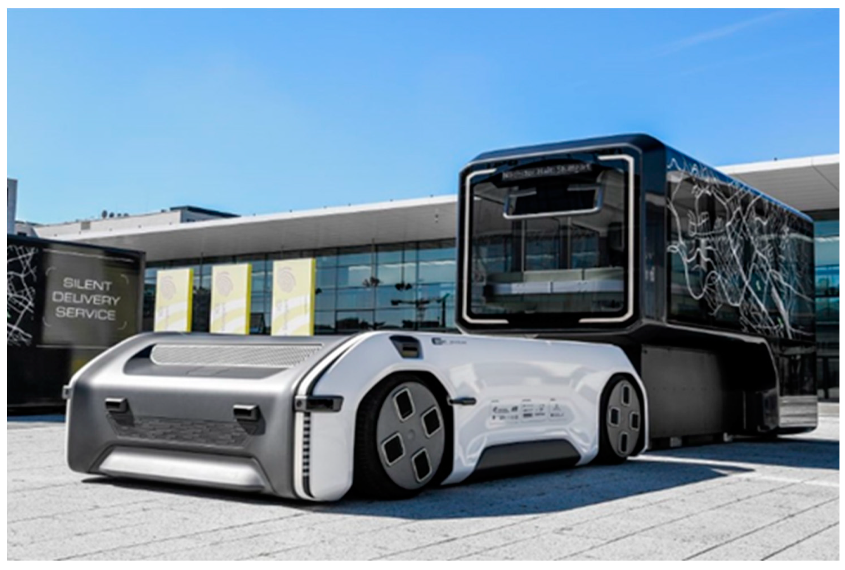
Figure 1 shows the Driveboard picking up a passenger capsule.
The capsule change is made possible by the geometry of the vehicle and a special lifting system. The Driveboard is U-shaped, open at the rear and can be lowered by 200 mm. This allows the Driveboard to move under the capsules when lowered, connect with them and then be raised back to the driving level. This function requires lifting actuators that enable the vehicle to be lowered and raised. In order to avoid track changes during the lifting process, a special subframe is also used [
2].
The selected concept for the lifting actuator is fully electromechanical and works with a cable winch that moves a roller block vertically along a profile rail guide. The lifting actuator connects the frame of the Driveboard, which is lifted, with the subframe, which does not change its level during the lifting process and enables the two components to move relatively to each other. A locking system is used to lock the actuators in the upper and lower end positions for safety and to relieve the stress on the cables. The locking system consists of locking bolts that are actuated by springs to lock and lifting magnets to unlock and connect form-fittingly to the housing. The lifting actuator is driven by a servomotor with an integrated gearbox, which applies the lifting force and controls the weight-driven lowering.
This paper explains the mechanical design in the context of the application, shows the design of the individual components and describes the structure of the linear actuator in detail.
2. Materials and Methods
2.1. Geometric and Physical Boundary Conditions
The lift actuator is the physical and functional interface between the subframe and the frame of the Driveboard. It must, therefore, be positioned between the two structural components and transmit all the forces that occur. Due to the selected actuator concept, the actuators must be positioned between two vertical structures.
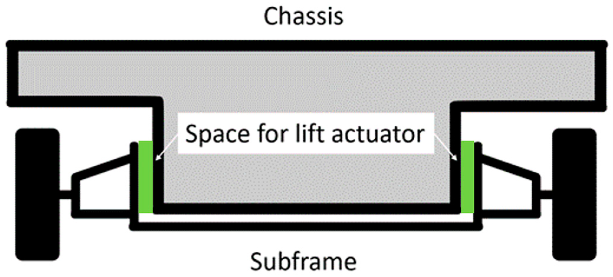
Figure 2 shows a schematic sketch of the cross-section view of the Driveboard at the front axle and indicates the position of the lifting actuators.
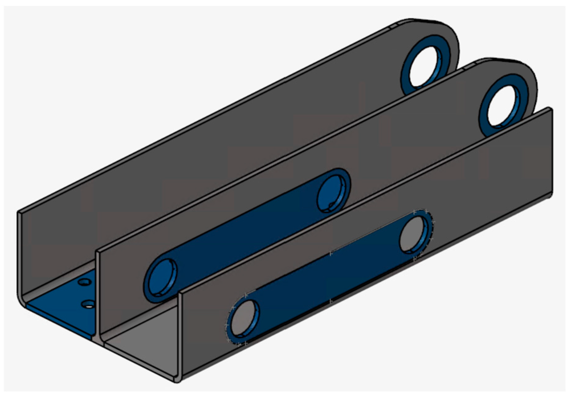
Figure 3 shows the surface provided on the subframe for attaching the lifting actuator. A total of four lifting actuators are installed, two on each of the symmetrically opposite side parts of the subframe. This also has the advantage that the lifting actuators can be built small, and the space between the body and the subframe is kept to a minimum.
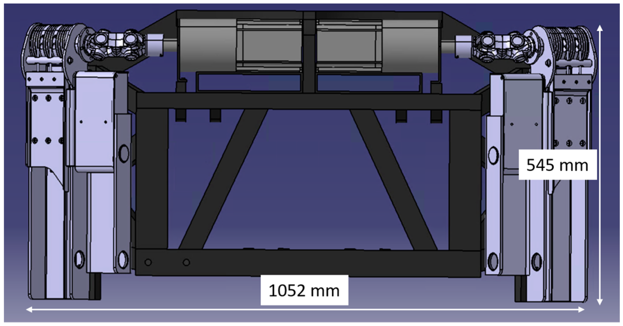
Figure 4 shows a side view of the driving stool with mounted lifting actuators; the figure also shows the size ratios.
To calculate the forces acting on the lifting actuators, the masses and the mass distribution of the Driveboard (see
Table 1) and the maximum accelerations of the standard load cases according to
Table 2 are used. The load cases vertical impact (2), longitudinal impact (3) and lateral impact (4) represent high quasi-static loads on the chassis components in all spatial directions. The U-Shift prototype is intended for a low driving speed, but the selected load cases can also potentially occur at low speeds (attenuated). As the wheel accelerations represent limit cases that only rarely occur, the yield strength is used below as the material parameter for the mechanical design of the components. A check of the fatigue strength of the components is recommended when the components are pursued further. By multiplying the wheel accelerations by the wheel load, the forces acting on the vehicle at the wheel contact point are obtained. While 40% of the vehicle mass is on the front axle when the Driveboard is empty, the proportion of the total mass on the front axle is reduced to 30% when the vehicle is fully loaded with a passenger capsule.
2.2. Lifting Actuator Concept
Several concepts were created and evaluated according to installation space, weight, efficiency, maintenance and costs with descending weighting [
4]. The concept described in this paper was selected and further developed on the basis of the geometric and physical boundary conditions. The basic structure is shown in
Figure 5, and the components are labelled in
Table 3. A servomotor drives the shaft (1), which is mounted in the housing (2) and connected to the cable winch (3). The three steel cables (4) are rolled up on the cable winch and connected to the adapter (5), which is screwed onto the roller block (6). The roller block is guided by the profile rail (7), which is also bolted to the housing. The locking mechanism (8) is also connected to the adapter, which moves parallel to the roller block in the housing and engages with locking bolts in the neighbouring walls of the housing. The locking bolts are constantly pressed outwards by springs and engage in the holes provided in the housing wall as soon as they are reached. The bolts are retracted by lifting magnets before a lifting operation.
2.3. Dimensioning
This chapter describes the methodology for designing the individual components. For simple geometries, strength theory equations can be used, while the underlying standards are used for standardised components. The strength verification of complicated geometries is carried out using simulation. The maximum front axle load and the maximum accelerations in each direction can be used to calculate the forces that act on the front axle and must, therefore, be transmitted via the subframe and the lifting actuators. The maximum forces occurring on a lifting actuator are summarised in
Table 4. For the following dimensioning, it is assumed that the forces acting on the front axle are distributed evenly over all four actuators.
2.3.1. Profile Rail Guide
The profile rail guide must support all forces in the x and y directions. In order to achieve the most compact design possible, a roller block with the following properties is selected:
Roller recirculation;
45° arrangement of the rolling elements;
No rolling element cage;
SLS design (slim, long, standard height).
The long design of the roller block is chosen because the vertical construction space is less critical than the horizontal. This also allows higher torques to be absorbed. The static dimensioning is carried out on the basis of DIN ISO 14728-2 [
5] and refers to time-independent maximum loads. The static load rating
C0 is calculated using the static safety factor
S0 and the statically equivalent load
P0, which correspond to the forces in the x and y directions from
Table 4.
Table 5, which takes into account the operating conditions of the linear guideway, is used to select a suitable safety factor. Depending on the application, the unknown torque loads and possible contamination of the guideway, the conditions in the second row apply. Conservatively, the highest safety factor of 12 is used for this category.
The note (*) in the last line of
Table 5 indicates that the roller block must not detach from the rail and that this must be prevented by design in applications where there is a potential risk of injury [
7]. Due to the cable winch, the roller block cannot leave the profile rail at the upper end. The connecting strut between the side parts of the subframe (see
Figure 3) prevents it from leaving the bottom end of the profile rail, as it would collide with the frame of the Driveboard first. As four actuators are installed, which are located at each corner of the U-shaped subframe and are arranged at an angle, the two structural components, the body of the Driveboard and the subframe, cannot be separated from each other even in the case of a complete failure of a profile rail guide. This ensures a critical aspect of operational safety. According to Formula (1) [
5]
the static load rating results in
.
The dynamic load rating is calculated in an analogue way to the static load rating in accordance with DIN ISO 14728-1 [
8]. In the application of this vehicle, the dynamic equivalent load represents the capsule change in the inclined position. For this scenario, the incline on country roads is considered. The slope downforce that occurs is calculated using the maximum longitudinal incline on country roads. According to the Road and Transport Research Association, this is 8.0% [
9] or
= 4.57°. The slope acceleration is calculated using Formula (2).
It results in .
As the bearing configuration is 45°, the orientation of the force relative to the profile rail can be ignored [
6]. Furthermore, torques are neglected in the calculation. The equivalent dynamic load is therefore calculated according to Formula (3).
to
.
According to the manufacturer’s recommendation, a safety factor of
S = 6 is selected for use in lifting mechanisms [
6]. After converting Formula (4), a dynamic load rating can be calculated.
It results in .
The profile rail guide must meet or exceed the static and dynamic load rating. As the static load is significantly higher, this is considered a selection criterion. The required loads are summarised in
Table 6.
2.3.2. Winch and Steel Cables
The cable winches must lift the maximum front axle load of 1500 kg. Due to the configuration of four actuators, each cable winch is subjected to a cable pulling force of
= 3678.75 N. The system is designed for one cable per winch. In order to ensure operational safety, even if one cable fails, more cables are installed per cable winch. The width of the cable winch allows the use of three cables per actuator. The design is carried out in accordance with DIN 15020 [
10].
In the first step, the drive unit group is determined according to DIN 15020 [
10]. This requires the average running time per day to be calculated in hours. Due to the requirements made in the project for the lifting cycles, an average running time of less than 0.125 h/d is achieved. Assuming a heavy load profile results in the engine group “1 D
m”. For drive units of this classification, the safety index, which indicates the ratio between breaking force and tensile force, must be at least 3. This condition is checked after determining the minimum cable diameter.
The coefficient
c is then determined. Non-elongation-free cables are assumed for this, as the load is guided by the profile rail guide, resulting in a small coefficient. The nominal strength
of the individual wires is assumed to be the lowest permissible value for the drive unit group of 1770
. The coefficient can be taken from DIN 15020 [
10] and is
c = 0.0710. The minimum cable diameter can be calculated with the coefficient c and the cable tensile force
S according to Formula (5) [
10].
The minimum cable diameter is therefore . The value is rounded up to the nearest integer with .
In addition to the values already listed, two further factors are required to calculate the safety factor. The influence of the load collective is taken into account by
k and the filling factor of the cables by
f. The calculation of the safety index
based on Formula (6) [
10]
to
= 3.69, which fulfils the requirements for the drive unit.
The minimum cable winch diameter can be calculated using Formula (7) [
10].
This results in
. The unitless coefficients
and
are taken from DIN 15020 [
10].
The groove radius in the cable winch for the steel cables is taken from DIN 15020 [
10] and is
.
To prevent the cables from unwinding, the cables are fixed in the drum with a grub screw and wrapped around the drum with more than two wraps in each position of the roller block. A plain bearing is provided for the drive shaft bearing, as this saves space and can absorb high surface pressures. According to DIN 15020, an efficiency of
= 0.96 is specified for this type of bearing [
10].
Table 7 summarises all the requirements for dimensioning the winch and cables.
2.3.3. Servomotor
All the information required to calculate the power data for the servomotor is known after the cable winch has been designed. The power can be calculated according to Formula (8).
The required power is = 255.47 W.
The required torque can be calculated using Formula (9) and is made up of the weight load per actuator, the effective radius of the cable winch and the efficiency factor.
After inserting all values, the required torque is = 116.88 Nm.
Table 8 summarises all the requirements for dimensioning the servomotors.
A motor from Heidrive is selected. The model HMD10-039-048-30 fulfils all requirements with a rated speed of 3000 min−1 and a standstill torque of 3.9 Nm. The motor is controlled via the mcDSA-E25XC motor controller from miControl. The position to be approached is specified as the control variable in revolutions, and the integrated sensor system confirms that the specified position has been reached.
2.3.4. Shaft
The shaft transmits the torque from the servomotor to the cable winch, is born on both sides, and carries the cable winch between the bearings. The shaft must be designed for bending, torsion and surface pressure. The bending and torsional torques are included in the combined load. The surface pressure is calculated last. The bending torque is induced by a line load and can be calculated for the present configuration using Formula 10 [
11]. The force
represents the cable tension force. The length
l is the distance between the bearings,
s is the bearing width.
The combined load can be calculated for general cases using Formula (11) [
11]. The torsional moment
represents the required torque of the servomotor.
The minimum shaft diameter can be calculated using Formula (12) and the permissible bending moment for steel S235 (EN 1.0038) [
11].
The calculated minimum diameter of
must be increased in order to accommodate a feather key. The resulting geometry is validated with a simulation. All requirements for the dimensioning of the shafts are summarised in
Table 9.
2.3.5. Locking Bolts
Each lifting actuator has a locking mechanism with two locking bolts that act simultaneously at both sides of the housing. As the locking bolts hold the position of the lifting actuator during the drive, they are each dimensioned with half the vertical force from
Table 4. The locking bolts must be designed for bending, shear and surface pressure. As normal stresses and shear stresses cannot simply be added according to the superposition principle, only the shear is considered for dimensioning, as shear stresses represent a higher load. The influence of the bending load is taken into account by a reduced permissible shear stress [
11]. The main shear equation is shown in Formula (13) [
11]. In this equation, the symbol
A refers to the cross-section area. The equation can be rearranged to solve for either the required diameter or the mean shear stress
.
This results in
. The maximum shear stress occurring for circular cross sections is calculated using Formula (14) [
11].
It results in
. The surface pressure that occurs is calculated using Formula (15), which contains the force acting on a bolt and the projected area.
This results in
. All requirements for dimensioning the locking bolts are summarised in
Table 10.
Red Magnetics ITS-LZ 3869-Z cylinder solenoids are used to actuate the bolts. The lifting magnets pull the bolts into the housing before the lifting process. Springs are used to push the bolts into the catches to disengage them for locking.
2.4. Topology Optimisation of the Housing
Topology optimisation is used to calculate the optimum material distribution within a given installation space, taking into account previously set requirements. The iterative optimisation process removes underutilised material until all specifications, such as a mass percentage to be retained, maximum stresses or rigidity, are achieved. The result is a topology that is adapted again in CAD, e.g., to the manufacturing process and then validated by means of an FE analysis [
3].
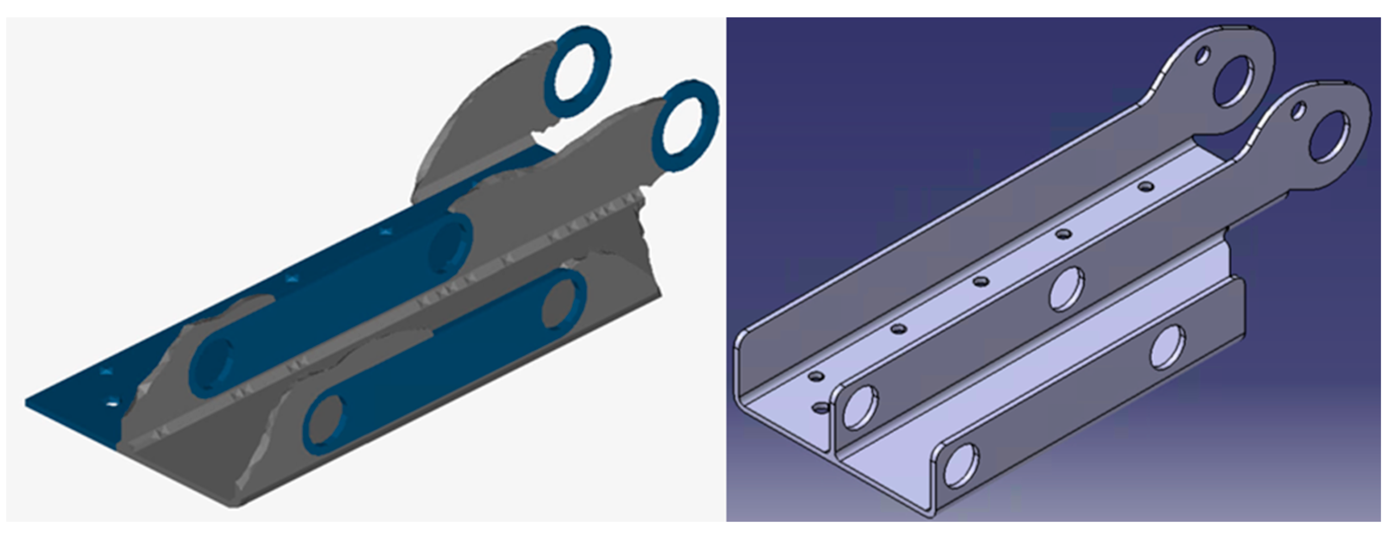
The concept defines the cross-section of the housing as well as the flange surfaces for the profile rail and the bearing mounts for the shaft and locking bolts. The material in the housing is to be reduced by using topology optimisation. The initial geometry for the housing is shown in
Figure 6. The maximum available installation space, the design space, is shown in grey, and the non-design space in blue.
The result of the topology optimisation with a target mass fraction of 60% and the final CAD model of the component can be seen in
Figure 7. Since only limited computing capacities are available, the components are divided into tetrahedral elements with a linear approach function (TETRA4). In order to achieve usable results despite the small number of nodes per element, an average element size of 1 mm is selected, which is small compared to the component dimensions. The outer wall without the locking bearing is almost completely removed. The corner of the housing on the bottom right-hand side has also been removed. The height of the existing walls was reduced. The material around the shaft bearings was completely removed on the side facing off from the stresses. This geometry is not completely carried over but is used as an indicator of where material can be removed.
2.5. FEA Simulation
For the simulation, settings must be made for the material, the mesh, the boundary conditions and the loads. Structural steel with values defined in
Table 11 is used as the starting material for the simulation. All models are calculated using a tetrahedron mesh with a cell size of 1 mm and curve-based fitting.
2.5.1. Housing
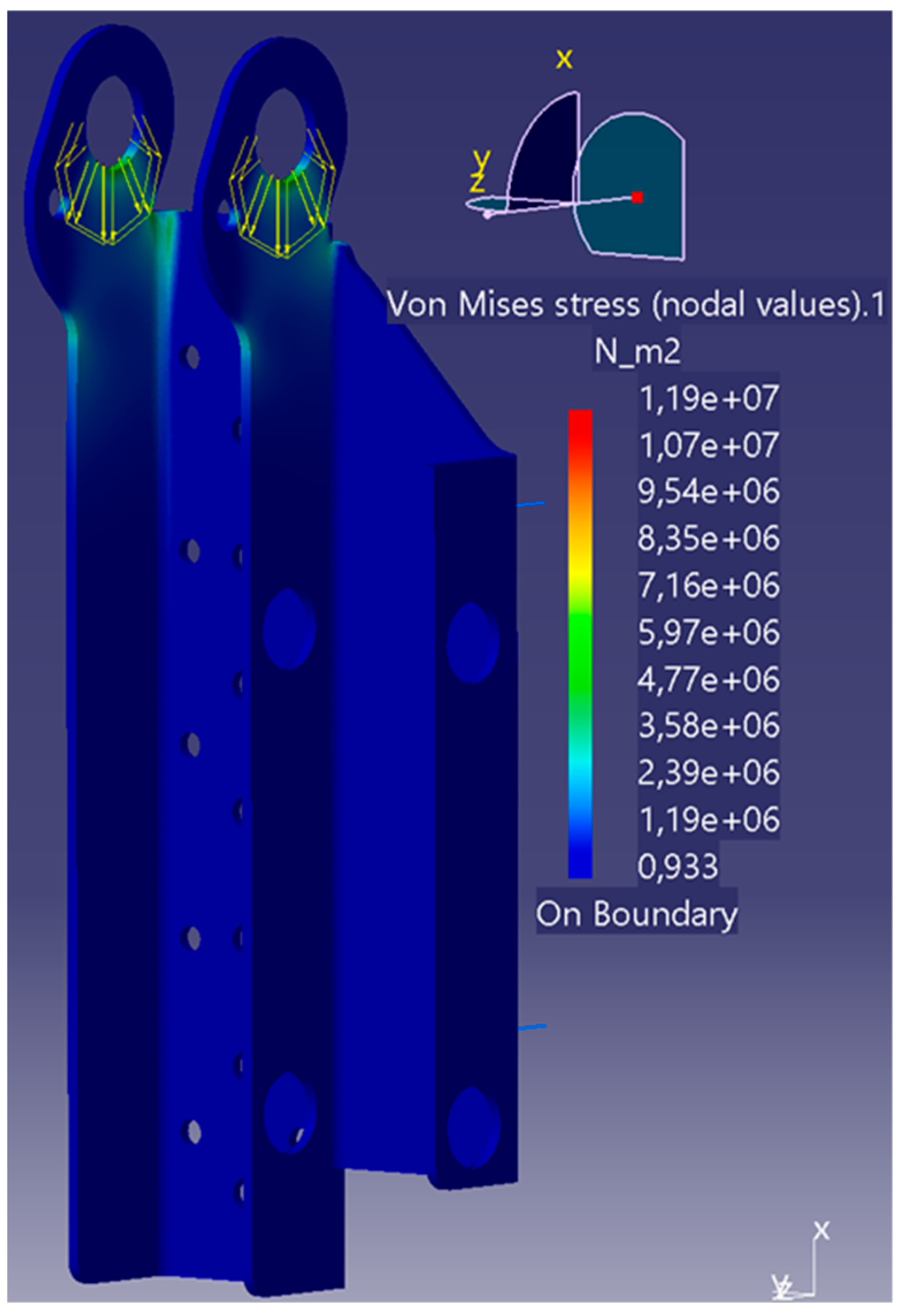
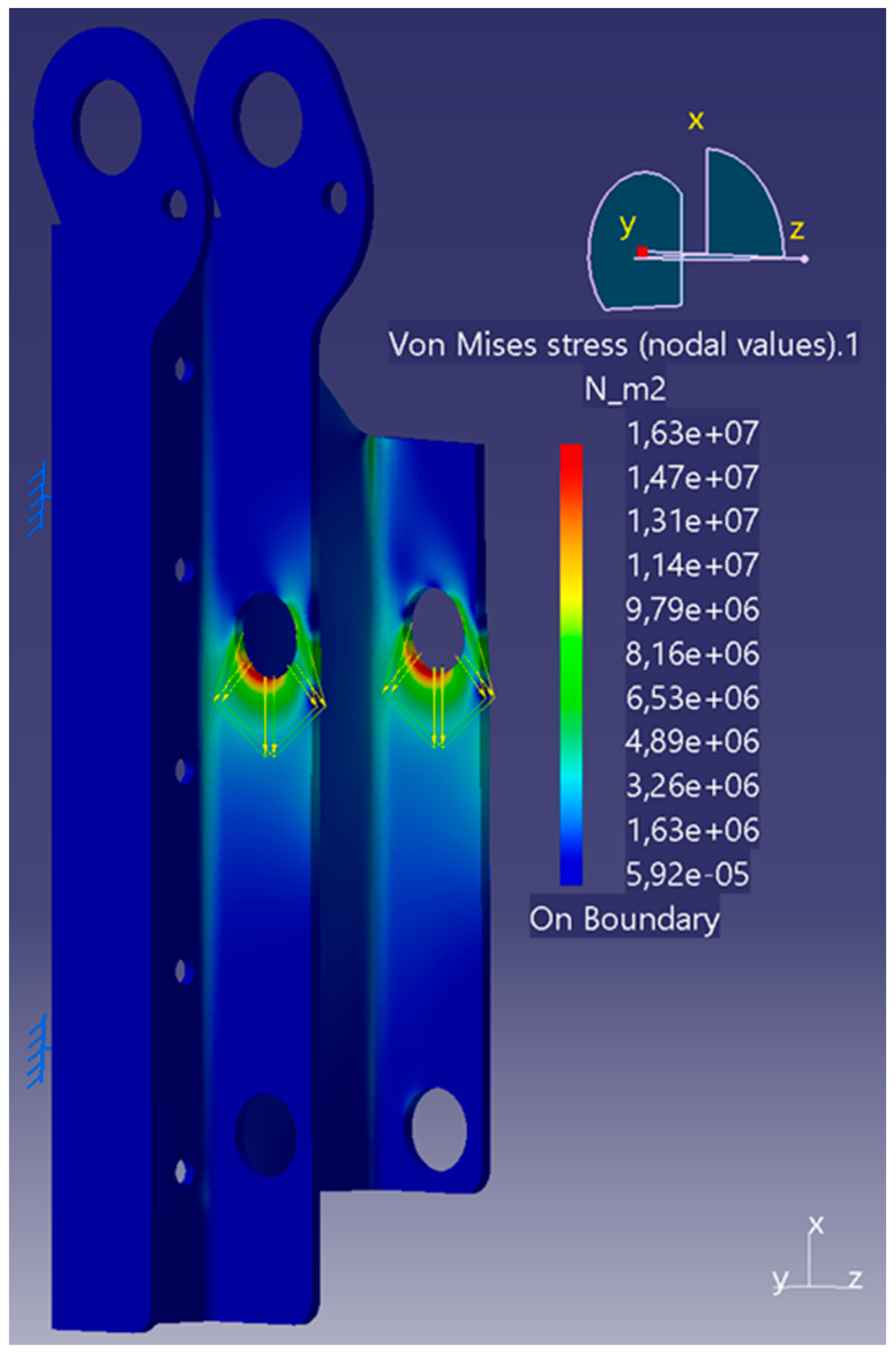
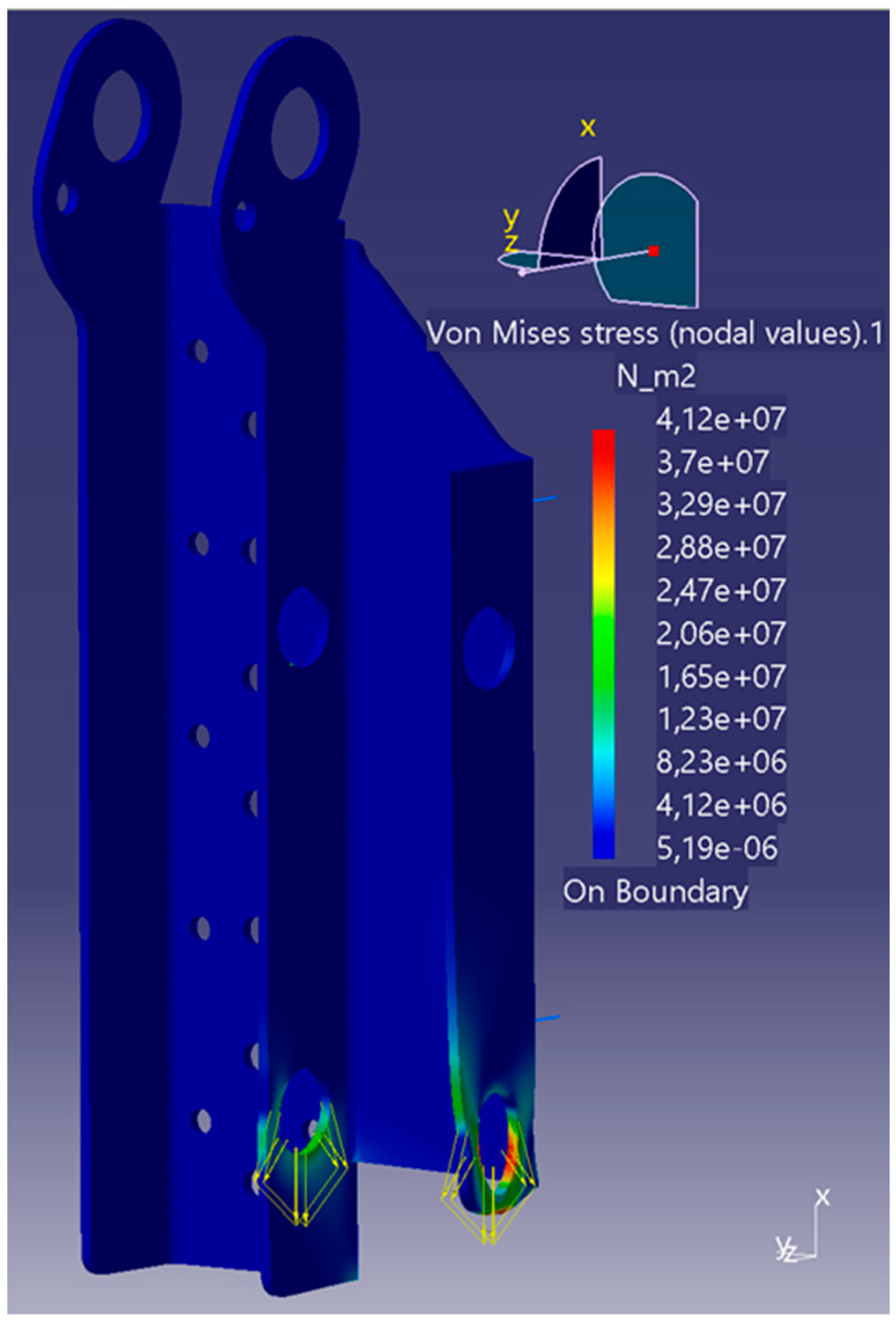
The geometry used for the simulation is derived from topology optimisation and features simplified geometries that are better suited for manufacturing. The housing is made of sheet steel with a wall thickness of 5 mm. The three load cases are calculated independently of each other, as they do not occur simultaneously. All boundary conditions and forces are shown in
Table 12.
Figure 8,
Figure 9 and
Figure 10 show the Von Mises stress distributions of the simulation. It is recognisable that the maximum stress occurs on the bearing surfaces, with secondary points of stress along the exposed 90° bends, as can be seen in the first two load cases. All maximum stresses and displacements are listed in
Table 13. The highest stresses of 41.2 MPa and the highest displacements are generated in Load Case 3.
The maximum deformation is 0.01 mm, and therefore, does not warrant the need for higher strength steel than necessary for the induced stresses. The high stresses in Load Case 3 are due to the lack of support material downward from the bearing surface compared to the other two load cases, especially on the outside wall, which has had material removed according to the topology optimisation and ease of manufacturing in mind/constraints.
Due to these low loads, simple structural steel such as S235 (EN 1.0038) can be used for housing, which has good availability within the EU.
2.5.2. Adapter
The adapter consists of a large flange surface that is screwed onto the roller block and a welded-on U-profile that holds the locking mechanism. In Load Case 1, forces are induced in the z-direction by the bearing surfaces for the locking bolts. Load Case 2 assumes the worst case for the cable attachment and applies a surface load to the model at the outer cable attachment with the lowest surrounding material volume. The exact boundary conditions and loads can be seen in
Table 14.
Figure 11 shows the Von Mises stress distribution for Load Case 1. It can be seen that the highest stresses occur in the transition from the U-profile to the flange surface at the upper end. The maximum stress of 436 MPa for material thicknesses of less than 16 mm is still within the load range of S460 with a yield strength of 460 MPa. The largest displacement of approx 0.71 mm also occurs in this load case. The displacement occurs with the free-standing wall and is directed inwards and, therefore, unproblematic, as there is no collision with the housing, which moves relative to the adapter.
Load Case 2 is shown in
Figure 12. The maximum stresses occur on the open side of the cable attachment. The stresses of 233 MPa are significantly lower than those of Load Case 1 and, therefore, have no further influence on the choice of material.
Table 15 shows the maximum stresses and displacements for both load cases.
2.5.3. Shaft
The shaft is simulated with the feather keys. For this purpose, all contact surfaces between the feather keys and the shaft are defined as a sliding connection. The feather keys are defined as firmly clamped. The sliding bearing surfaces are defined as such, and the load of the cable winch is projected onto the top of the shaft. The torque is induced at the shaft end. All constraints and loads are listed in
Table 16.
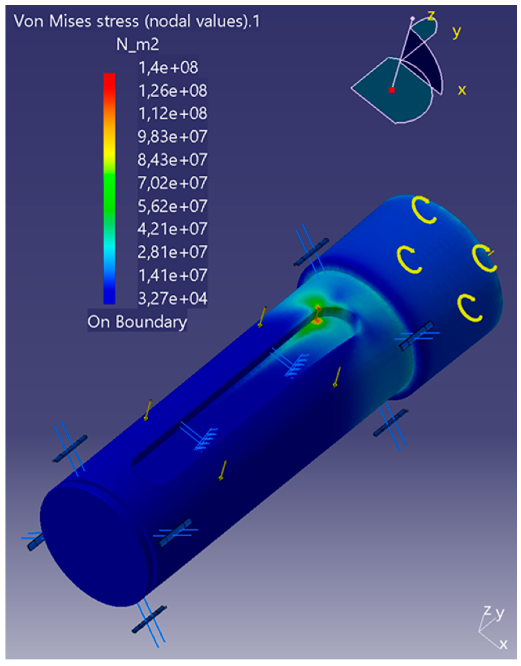
The maximum stresses occur at the end of the contact surface between the shaft and the feather key close to the torque input, as can be seen in
Figure 13. It can be assumed that these stress concentrations occur due to the rigidly clamped feather keys and the sharp end of the contact surfaces, which do not optimally represent reality. Nevertheless, the maximum stresses and displacements, which are also summarised in
Table 17, are low enough to allow the use of structural steel S235 (EN 1.0038).
3. Results
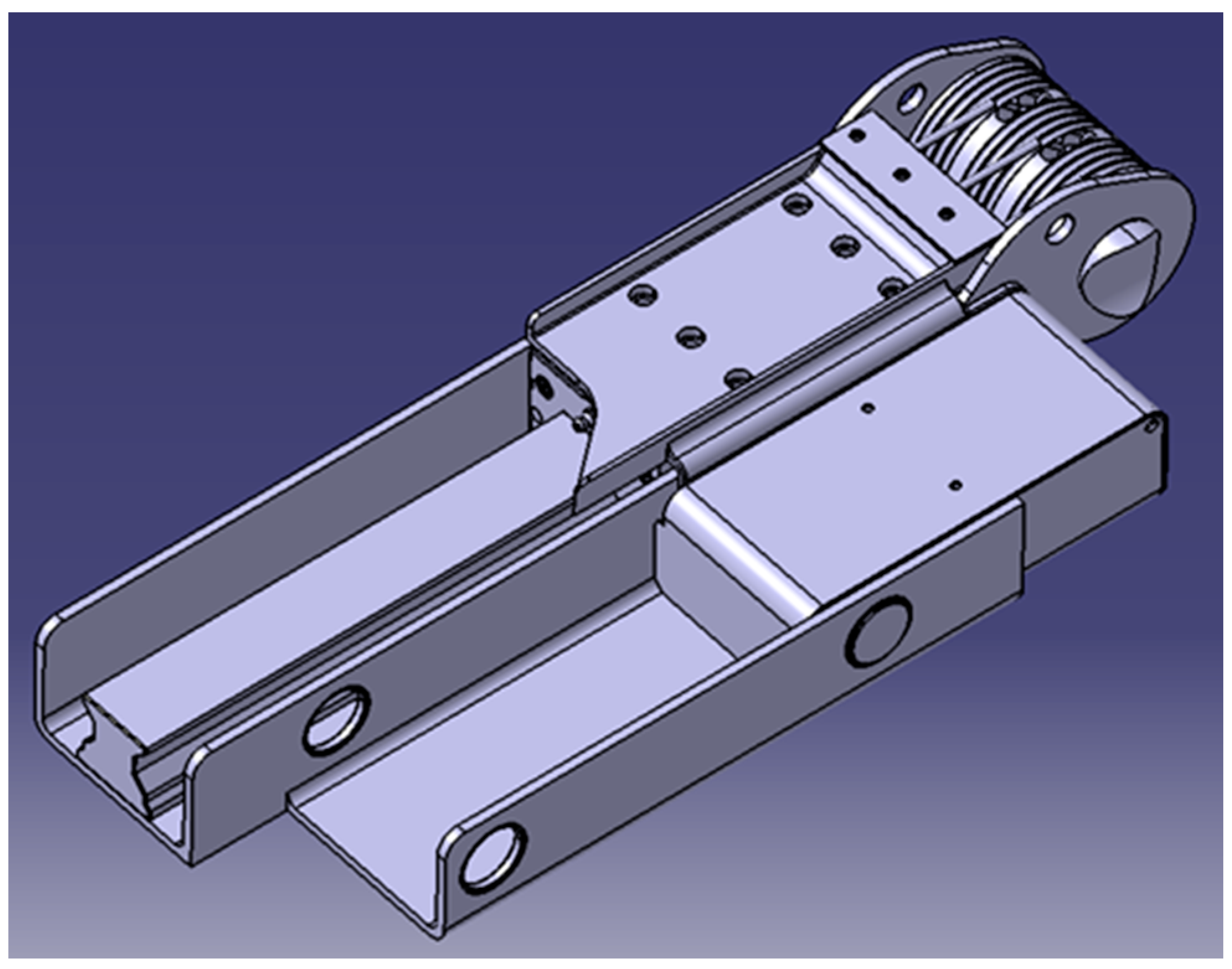
Figure 14 shows the final CAD model of the assembly of the lifting actuator. The housing, the adapter and the shaft correspond to the figures already shown in the simulation chapter. The locking bolts are locked in the upper position, which represents the travelling position.
Topology optimisation was used to identify areas of the housing with excess material. The optimised housing should nevertheless retain a simple geometry and protect the moving components in the housing. Therefore, the walls were reduced to the height of the adapter, and the entire bottom, which rests against the subframe, was retained. The material around the shaft bearings is also retained to protect the cable winch. The channel for the locking mechanism was shortened at the lower end, and a triangular geometry was removed at the top. The topology optimisation and the FEA simulation suggest that the material thickness of 5 mm can also be reduced. However, this is retained in order to prevent the walls from buckling or twisting and to provide sufficient bearing space.
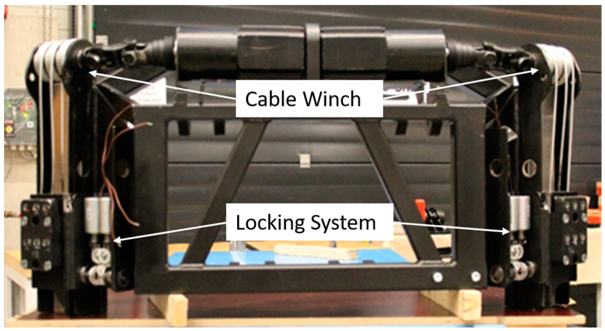
Two lifting actuators can be seen in
Figure 15 and are already mounted on a side part of the subframe. The locking mechanism is locked in the lower position here, which represents the capsule change position. The servomotors are installed above the frame and drive the cable winches by using a cardan shaft due to the angular offset.
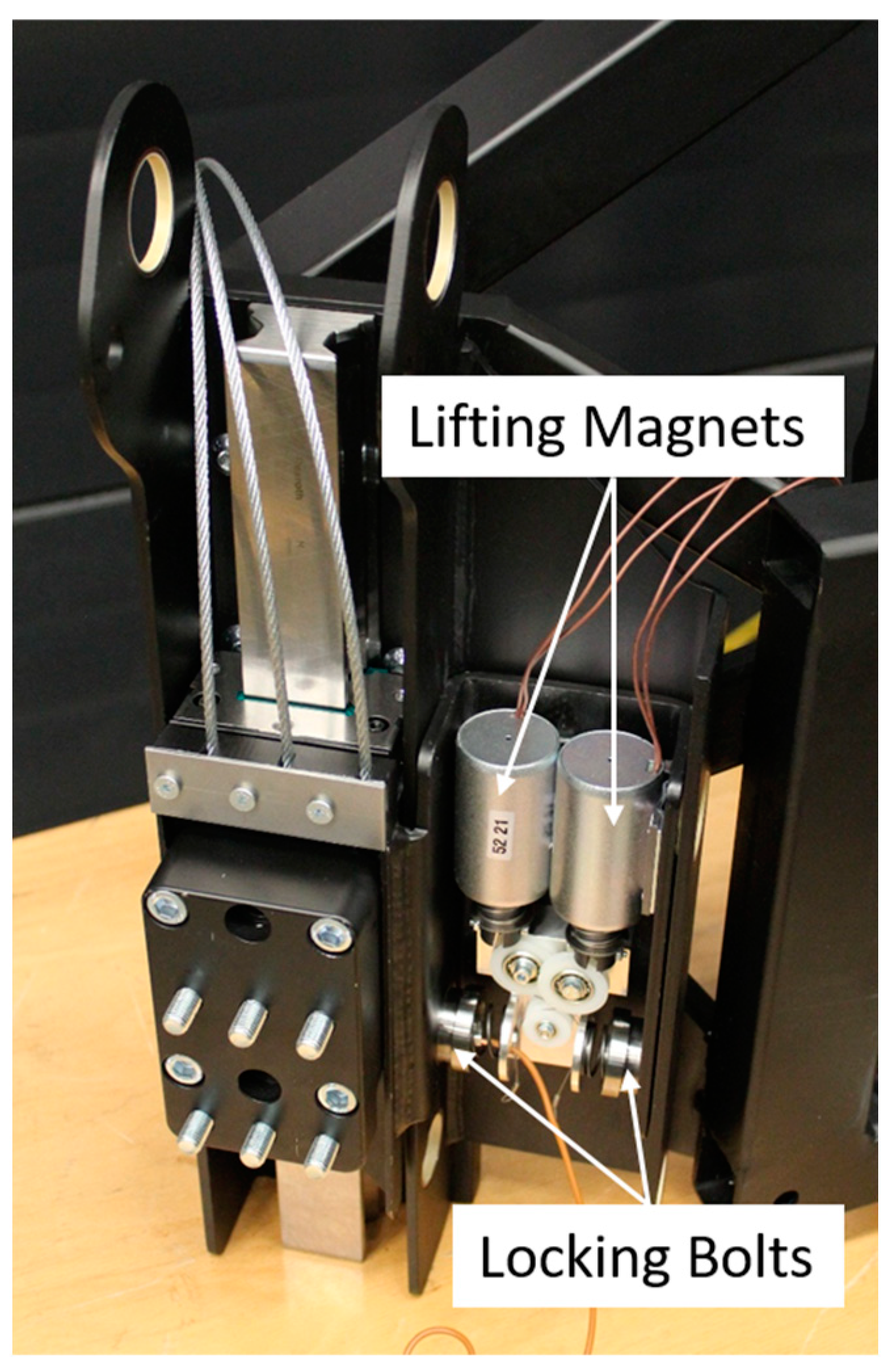
Figure 16 shows a close-up view of a lifting actuator. The actuator is also locked in the lower position in this picture. In this view, the cable winch is not yet mounted, and the plain pressed-in bearings of the shaft and the cable attachment in the adapter are clearly visible.
4. Discussion
The design is mostly carried out with the help of standards, manufacturer catalogues and scientific manuals. These materials provide calculations in descending order, with which components can be fully or pre-dimensioned. FEA simulations and topology optimisations were used as further tools for dimensioning. Topology optimisation was used to reduce the mass of the housing, but the focus was also placed on simple geometry. The simulation results show that the geometries can withstand the loads, but by using the housing as an example, even more material could have been saved, and material utilisation could have been increased.
The lifting actuator is designed as a complete unit to allow for separate development. This is particularly useful if other systems have not yet been finalised and, therefore, only the interfaces need to be defined or adapted. However, an integrated development of the lifting actuator is also conceivable and offers greater potential for material, weight and installation space savings. However, this approach to concept and product development is more complex. Further advantages of the separate development are the adjustability of the actuators as well as the possibility of pre-assembly and easier interchangeability due to the flange connection.
The lifting actuator developed enables the lifting process under all the required boundary conditions of the U-Shift project, which could not be realised on the basis of existing systems. The lifting actuator connects the frame of the Driveboard, which is lifted, with the subframe and does not change its level during the lifting process. It enables the two components to move relative to each other and thus prevents changes in track width during the lifting process. For safety and to take the strain off the cables, a locking system is used to lock the drives in the upper- and lower-end positions.
The tests carried out so far have shown that the overall system even exceeds the requirements. It is possible to lift the vehicle in a shorter time and move a higher total mass than originally assumed. In the course of the project, the prototypes will be tested even more extensively in the Driveboard and further developed on the basis of the knowledge gained.
Author Contributions
Conceptualisation, F.W.; methodology, F.W.; validation, N.L.O.; formal analysis, F.W.; investigation, N.L.O.; resources, F.W.; data curation, F.W. and N.L.O.; writing—original draft preparation, F.W. and N.L.O.; writing—review and editing, F.W. and M.F.; visualisation, F.W. and N.L.O.; supervision, M.F. and F.G. All authors have read and agreed to the published version of the manuscript.
Funding
This research was funded by the Ministry of Economic Affairs, Labour and Tourism Baden-Württemberg (Ministerium für Wirtschaft, Arbeit und Tourismus Baden-Württemberg.
Data Availability Statement
Data are contained within the article.
Acknowledgments
We would like to thank the Ministry of Economic Affairs, Labour and Tourism Baden-Württemberg (Ministerium für Wirtschaft, Arbeit und Tourismus Baden-Württemberg) for funding the “U-Shift II” project. The responsibility for the content of this work lies with the authors.
Conflicts of Interest
The authors declare no conflict of interest.
References
- Deutsches Zentrum für Luft- und Raumfahrt e.V. Projekt U-Shift II (Demonstrator). Picture: DLR, CC-BY-ND. Available online: https://verkehrsforschung.dlr.de/de/projekte/u-shift/u-shift-ii-demonstrator (accessed on 23 June 2023).
- Weitz, F.; Frey, M.; Gauterin, F. Methodical Design of a Subframe for a Novel Modular Chassis Concept without Knowledge of Final Vehicle Parameters. SAE Int. J. Commer. Veh. 2024, 17, 91–101. [Google Scholar] [CrossRef]
- Ersoy, M. Fahrwerkentwicklung. In Fahrwerkhandbuch, 5th ed.; Gies, S., Ed.; Springer Fachmedien Wiesbaden GmbH: Wiesbaden, Germany, 2017; Volume 5, pp. 264–268. [Google Scholar]
- Ostendorff, N. Aktorkonzept für die Niveauregulierung in einemneuartigen Fahrzeugkonzept. Bachelor’s Thesis, Karlsruher Institut für Technologie, Karlsruhe, Germany, 2021. [Google Scholar]
- DIN ISO 14728-2:2018-10; Rolling Bearings—Linear Motion Rolling Bearings—Part 2: Static Load Ratings. Beuth Verlag GmbH: Berlin, Germany, 2018.
- Roller Rail Systems (R999000354). pp. 26–29. Available online: https://www.boschrexroth.com/en/de/media-details/838ed56e-6e53-45c1-a550-ca83e811ca1b (accessed on 19 July 2023).
- DIN 637:2016-12; Rolling Bearings—Safety Regulations for Dimensioning and Operation of Profiled Rail Guides with Recirculating Rolling Elements. Beuth Verlag GmbH: Berlin, Germany, 2016.
- DIN ISO 14728-1:2018-10; Rolling Bearings—Linear Motion Rolling Bearings—Part 1: Dynamic Load Ratings and Rating Life. Beuth Verlag GmbH: Berlin, Germany, 2018.
- Strassenbau: Grenz- und Richtwerte: Landstraßen. Available online: https://www.bauformeln.de/strassenbau/grenz-und-richtwerte/landstrassen/ (accessed on 19 July 2023).
- DIN 15020-1:1974-02; Lifting Appliances; Principles Relating to Rope Drives; Calculation and Construction. Beuth Verlag GmbH: Berlin, Germany, 1974.
- Böge, A.; Böge, W. Handbuch Maschinenbau Grundlagen und Anwendungen der Maschinenbau-Technik; 24. Auflage; Springer Fachmedien Wiesbaden GmbH: Wiesbaden, Germany; pp. 307–308, 763–790.
Figure 1.
Driveboard (on the left) drives up to passenger capsule (on the right) [
1].
Figure 1.
Driveboard (on the left) drives up to passenger capsule (on the right) [
1].
Figure 2.
Cross-section view at the front axle of the Driveboard, green: space for lift actuator.
Figure 2.
Cross-section view at the front axle of the Driveboard, green: space for lift actuator.
Figure 3.
Isometric view of the subframe CAD model.
Figure 3.
Isometric view of the subframe CAD model.
Figure 4.
Sideview of the subframe with lifting actuator.
Figure 4.
Sideview of the subframe with lifting actuator.
Figure 5.
Schematic sketch of the lifting actuator.
Figure 5.
Schematic sketch of the lifting actuator.
Figure 6.
Initial geometry for topology optimisation, grey: designspace; blue: non-designspace.
Figure 6.
Initial geometry for topology optimisation, grey: designspace; blue: non-designspace.
Figure 7.
Left: Output geometry after topology optimisation; right: CAD model of final component.
Figure 7.
Left: Output geometry after topology optimisation; right: CAD model of final component.
Figure 8.
FEA simulation of housing with Load Case 1.
Figure 8.
FEA simulation of housing with Load Case 1.
Figure 9.
FEA simulation of housing with Load Case 2.
Figure 9.
FEA simulation of housing with Load Case 2.
Figure 10.
FEA simulation of housing with Load Case 3.
Figure 10.
FEA simulation of housing with Load Case 3.
Figure 11.
FEA simulation of adapter with Load Case 1.
Figure 11.
FEA simulation of adapter with Load Case 1.
Figure 12.
FEA simulation of adapter with Load Case 2.
Figure 12.
FEA simulation of adapter with Load Case 2.
Figure 13.
FEA simulation of shaft with Load Case 1.
Figure 13.
FEA simulation of shaft with Load Case 1.
Figure 14.
CAD model of final lifting actuator.
Figure 14.
CAD model of final lifting actuator.
Figure 15.
Left side of subframe with attached lifting actuators.
Figure 15.
Left side of subframe with attached lifting actuators.
Figure 16.
Close up side view of lifting actuator attached to the subframe.
Figure 16.
Close up side view of lifting actuator attached to the subframe.
Table 1.
Driveboard mass and mass distribution.
Table 1.
Driveboard mass and mass distribution.
| Configuration/Mass | Total Mass | Front Axle Load | Rear Axle Load |
|---|
| Empty Driverboard | 1800 kg | 1080 kg | 720 kg |
| Maximum vehicle mass | 5000 kg | 1500 kg | 3500 kg |
Table 2.
Standard load cases for structural strength [
3].
Table 2.
Standard load cases for structural strength [
3].
| | Standard Load Cases | Acceleration [g] |
|---|
| x | y | z |
|---|
| 1 | Stationary car | 0.00 | 0.00 | −1.00 |
| 2 | Vertical impact 3.0 g | 0.00 | 0.00 | −3.00 |
| 3 | Longitudinal impact 2.50 g | 2.50 | 0.00 | −1.00 |
| 4 | Lateral impact 2.50 g | 0.00 | 2.50 | −1.00 |
| 5 | Cornering right 1.25 g | 0.00 | 1.25 | −1.00 |
| 6 | Braking while cornering | 0.75 | 0.75 | −1.00 |
| 7 | Braking backwards 1.0 g | 1.00 | 0.00 | −1.00 |
| 8 | Accelerate −0.5 g | −0.5 | 0.00 | −1.00 |
| 9 | Accelerating while cornering 0.7 g | −0.5 | 0.5 | −1.00 |
| 10 | Diagonal load | 0.00 | 0.00 | −1.75 |
| 11 | Vertical spring in 2.25 g | 0.00 | 0.00 | −2.25 |
| 12 | Vertical spring out 0.75 g | 0.00 | 0.00 | −0.75 |
| 13 | Cornering right 0.75 g | 0.00 | 0.75 | −1.00 |
| 14 | Cornering left 0.75 g | 0.00 | −0.75 | −1.00 |
| 15 | Braking 0.75 g | 0.75 | 0.00 | −1.00 |
| 16 | Accelerate −0.5 g | −0.5 | 0.00 | −1.00 |
Table 3.
Lifting actuator components.
Table 3.
Lifting actuator components.
| Number | Component |
|---|
| 1 | Shaft |
| 2 | Housing |
| 3 | Cable Winch |
| 4 | Steel Cables |
| 5 | Adapter |
| 6 | Roller Block |
| 7 | Profile Rail |
| 8 | Locking Mechanism Assembly |
| 9 | Locking Bolt |
Table 4.
Maximum forces acting on one lifting actuator.
Table 4.
Maximum forces acting on one lifting actuator.
| Axis | x | y | z |
|---|
| Force [N] | 9196.88 | 9196.88 | 11,036.25 |
Table 5.
Use case-dependent security factors for linear guides [
6].
Table 5.
Use case-dependent security factors for linear guides [
6].
| Conditions of Use | Static Load Safety Factor S0 |
|---|
| Overhead arrangements and applications representing a high hazard potential. | ≥12 |
| High dynamic load when at a standstill, contamination. | 8…12 |
| Normal dimensioning of machinery and plant without full knowledge of the load parameters or connection details. | 5…8 |
| Full knowledge of all the load data. Vibration-free operation is ensured. | 3…5 |
| If there are health and safety hazards, paragraph 5.1.3 of DIN 637 is to be observed. | * |
Table 6.
Requirements for dimensioning of the profile rail guide.
Table 6.
Requirements for dimensioning of the profile rail guide.
| Property | Value | Unit |
|---|
| 12 | - |
| 9196.88 | N |
| 110,362.50 | N |
| 292.50 | N |
| 1500 | kg |
| 0.78 | |
| 6 | - |
| 1755 | N |
Table 7.
Requirements for dimensioning of winch and steel cables.
Table 7.
Requirements for dimensioning of winch and steel cables.
| Property | Value | Unit |
|---|
| 0.071 | - |
| 3678.75 | N |
| 1770 | |
| 0.85 | - |
| 0.46 | - |
| 3.69 | |
| 11.2 | - |
| 1 | - |
| 5 | mm |
| 56 | m |
Table 8.
Requirements for dimensioning of the servomotor.
Table 8.
Requirements for dimensioning of the servomotor.
| Property | Value | Unit |
|---|
| 3678.75 | N |
| 0.2 | m |
| 3 | s |
| 0.96 | - |
| 0.056 | m |
| 0.005 | m |
| 255.47 | W |
| 116.88 | Nm |
Table 9.
Requirements for design of the shafts.
Table 9.
Requirements for design of the shafts.
| Property | Value | Unit |
|---|
| 3678.75 | N |
| 88 | mm |
| 5 | mm |
| 45,064.69 | |
| 116,876.95 | |
| 110,797.08 | |
| 130 | |
| 3 | - |
| 20.43 | mm |
Table 10.
Requirements for dimensioning of the locking bolts.
Table 10.
Requirements for dimensioning of the locking bolts.
| Property | Value | Unit |
|---|
| 5518.13 | N |
| 30 | mm |
| 7.81 | |
| 10.41 | |
| 5 | mm |
| 36.79 | |
Table 11.
Material properties of structural steel for FEA simulation.
Table 11.
Material properties of structural steel for FEA simulation.
| Property | Value | Unit |
|---|
| Young’s Modulus | 210 | GPa |
| Poisson’s Ratio | 0.3 | - |
| Density | 7.85 | |
Table 12.
Load cases for FEM Simulation of the housing.
Table 12.
Load cases for FEM Simulation of the housing.
| Load Case | Description | Force [N] | Direction (Model) |
|---|
| Constraint | Flange surface restraint via “Clamp” feature and sliding bearing on the backside. | N/A | N/A |
| Load Case 1 | Load on shaft bearing surfaces via “bearing load” feature. | 3678.75 | Neg. x-axis |
| Load Case 2 | Load on upper locking bolt bearing surfaces via “bearing load” feature. | 11,036.25 | Neg. x-axis |
| Load Case 3 | Load on lower locking bolt bearing surfaces via “bearing load” feature. | 11,036.25 | Neg. x-axis |
Table 13.
Results of housing simulation.
Table 13.
Results of housing simulation.
| Load Case | Max. Tension [MPa] | Max Deformation [mm] |
|---|
| x | y | z |
|---|
| Load Case 1 | 11.9 | −0.00110 | −0.00292 | 0.00133 |
| Load Case 2 | 16.3 | −0.00247 | 0.00346 | 0.00080 |
| Load Case 3 | 41.2 | −0.01020 | −0.00233 | −0.00134 |
Table 14.
Load cases for FEM simulation of the adapter.
Table 14.
Load cases for FEM simulation of the adapter.
| Load Case | Description | Force [N] | Direction (Model) |
|---|
| Constraint | Flange surface restraint via “Clamp” feature | unlimited | none |
| Load Case 1 | Load on locking bolt bearing surfaces via “bearing load” feature | 11,036.25 | Pos. x-axis |
| Load Case 2 | Load on cable end retaining collar via “distributed force” | 3678.75 | Pos. x-axis |
Table 15.
Results of adapter simulation.
Table 15.
Results of adapter simulation.
| Load Case | Max. Tension [MPa] | Max Deformation [mm] |
|---|
| x | y | z |
|---|
| Load Case 1 | 436 | 0.71300 | 0.35700 | −0.50100 |
| Load Case 2 | 234 | 0.02840 | −0.00827 | −0.03130 |
Table 16.
Load cases for FEM simulation of the shaft.
Table 16.
Load cases for FEM simulation of the shaft.
| Load Case | Body | Description | Force | Direction (Model) |
|---|
| Constraint | Shaft | Bearing surfaces are restraint via sliding contact | unlimited | none |
| Constraint | Feather Key | Restraint via flange on two perpendicular sides | 116.88 [Nm] | Pos. y-axis |
| Load Case 1 | Shaft | Torque applied on one end, distributed force on upper shaft surface | 3678.75 [N] | Neg. z-axis |
Table 17.
Results of shaft simulation.
Table 17.
Results of shaft simulation.
| Load Case | Max. Tension [MPa] | Max Deformation [mm] |
|---|
| x | y | z |
|---|
| Load Case 1 | 140 | −0.00155 | 0.00020 | 0.00915 |
| Disclaimer/Publisher’s Note: The statements, opinions and data contained in all publications are solely those of the individual author(s) and contributor(s) and not of MDPI and/or the editor(s). MDPI and/or the editor(s) disclaim responsibility for any injury to people or property resulting from any ideas, methods, instructions or products referred to in the content. |
© 2024 by the authors. Licensee MDPI, Basel, Switzerland. This article is an open access article distributed under the terms and conditions of the Creative Commons Attribution (CC BY) license (https://creativecommons.org/licenses/by/4.0/).
