Abstract
The primary objective of this research is to address the existing gap about the use of a path-planning algorithm that will reduce energy consumption in off-road applications of tracked electric vehicles. The study focuses on examining various off-road terrains and their impact on energy consumption to validate the effectiveness of the proposed solution. To achieve this, a tracked electric vehicle energy model that incorporates vehicle dynamics is developed and verified using real vehicle driving data logs. This model serves as the foundation for devising a strategy that can effectively enhance the energy efficiency of off-road tracked electric vehicles in real-world scenarios. The analysis involves a thorough examination of different off-road terrains to identify strategies that can adapt to diverse landscapes. The path planning strategy employed in this study is a modified version of the A*, called the Energy-Efficient Path Planning (EEPP) algorithm, specifically tailored for the dynamic energy consumption model of off-road tracked electric vehicles. The energy consumption of the produced paths is then compared using the validated energy consumption model of the tracked electric vehicle. It is important to note that the identification of an energy-efficient path heavily relies on the characteristics of the vehicle and the dynamic energy consumption model that has been developed. Furthermore, the algorithm takes into account real-world and practical considerations associated with off-road applications during its development and evaluation process. The results of the comprehensive analysis comparing the EEPP algorithm with the A* algorithm demonstrate that our proposed approach achieves energy savings of up to 6.93% and extends the vehicle’s operational range by 7.45%.
1. Introduction
Off-road vehicles play a pivotal role in industries such as agriculture, mining, and construction, as highlighted by the European Commission [1]. These vehicles operate in challenging environments, facing terrains that demand efficient energy usage for optimal performance [2]. Electric off-road vehicles face limitations in energy storage and consumption due to the nature of battery technology [3]. This results in a need for efficient utilization of available energy to enhance operational range and minimize downtime. Traditional path-planning methods primarily focused on the shortest distance or time [4]. However, these methods might not consider energy efficiency as a primary criterion, especially in off-road scenarios. Energy-efficient path planning aims to optimize resource usage, ensuring vehicles operate within their energy constraints while completing tasks [5]. Reducing energy consumption aligns with sustainability goals reducing carbon emissions and environmental impact [6]. Optimizing energy usage reduces operational costs by minimizing recharging frequency and maintenance expenses [7]. Research on energy-efficient path planning drives advancements in algorithms and technologies for vehicles, leading to smarter and more adaptable vehicles [8]. Efficient energy usage contributes to vehicle reliability, ensuring safe operations even in remote or challenging locations [9]. Energy-efficient path planning is a multidisciplinary field, drawing from robotics, vehicle dynamics, and optimization strategies. Studies like those referenced showcase the growing importance of considering energy efficiency as a fundamental criterion in path planning for off-road vehicles. Such considerations have significant implications for sustainability, cost-effectiveness, technological innovations, and the overall reliability of off-road vehicle operations.
Off-road tracked electric vehicles are designed with tracks or treads for mobility, providing enhanced traction and stability in rough terrains [10]. They typically integrate electric propulsion systems powered by batteries, offering quieter operation and reduced emissions compared to traditional combustion-powered vehicles [11]. Tracked electric vehicles excel in traversing challenging landscapes like mud, sand, or steep inclines due to their superior traction and low ground [12]. These vehicles often exhibit greater maneuverability and stability compared to their wheeled counterparts, making them ideal for off-road operations in various industries [13]. The electric propulsion system in these vehicles typically consists of electric motors powered by batteries, providing torque and power to drive the tracks [13]. Studies by Everitt et al. showcase the advancements in electric propulsion for tracked vehicles in military contexts [14]. Off-road tracked electric vehicles find applications in agriculture, mining, forestry, military, and even recreational activities due to their adaptability and versatility [13]. Their ability to navigate challenging terrains makes them suitable for tasks such as hauling heavy loads, exploration, and accessing remote or rugged areas [13].
Off-road environments often pose challenges like uneven terrain, slopes, and unpredictable conditions that demand efficient energy utilization [15]. While the road options on the highway are limited, the road options on off-road terrain depend on the limits of the vehicle and include many options. Therefore, although energy consumption on the highway generally depends on driving characteristics, the choice of the route to be taken in off-road terrain also constitutes the biggest source of energy consumption. Steep slopes have the potential to diminish the grip between the track and the ground, thereby necessitating a greater amount of power to sustain forward motion. Consequently, the powertrain of the vehicle is compelled to exert more effort to counteract the gravitational forces, leading to an escalation in energy consumption. Moreover, off-road driving frequently entails sudden acceleration and braking maneuvers to navigate through obstacles or negotiate steep inclines and declines. These rapid alterations in speed give rise to energy losses as a result of the frequent transitions between kinetic and potential energy. During acceleration, energy is expended, while, during braking, it must be dissipated as heat. This variability in driving conditions can lead to suboptimal engine performance, thereby diminishing the overall efficiency of the powertrain and augmenting energy consumption. Optimizing energy consumption ensures that vehicles can perform tasks effectively, minimizing interruptions due to recharging or refueling. Efficient energy usage extends the operational range of off-road vehicles, crucial in industries like mining or agriculture where vehicles cover vast areas [16]. Studies about advanced powertrain control strategies focus on methods to extend range without compromising productivity [17]. Energy-efficient vehicles lower operating costs by reducing fuel or electricity consumption and these cost savings are especially critical in industries with high fuel/electricity expenses, contributing to overall profitability.
The management of energy holds significant importance in the domain of ground vehicles. These vehicles often navigate complex off-road terrains, where energy consumption poses limitations on their operational range and duration. Researchers have delved into research on energy storage technology, electrical machine control techniques, and internal combustion engine advancements to enhance energy efficiency in this context [18].
A range of commonly used path planning algorithms including the A-star algorithm and Dijkstra’s algorithm is specifically developed to determine the closest route in the grid map, thinking of cost as a distance to the neighbor nodes on the grid map. In the A-star algorithm, to improve performance in the algorithm, a priority is given to the neighbor who is akin to the destination. It allows minimizing the area to be explored and time during the path planning. Some other algorithms, for example, Probabilistic Roadmap, work with the same principle as Dijkstra’s algorithm but sampling nodes in free space and connecting them directly to calculate the cost. In the literature, there are numerous optimization approaches, including grey wolf, ant colony, particle swarm, and bat optimization algorithms, that have been proposed [19].
In prior studies, researchers focused on enhancing obstacle avoidance and path smoothness. Szczepanski et al. introduced a local path-planning algorithm incorporating future movement prediction into an artificial potential field to enhance obstacle avoidance, also proposing virtual obstacles, known as “top quarks”, to prevent unsmooth and oscillating motion caused by local minima. However, the algorithm’s robustness and practical applicability were not fully addressed, necessitating further validation in diverse real-world scenarios [19]. Additionally, Al-Ansarry and colleagues combined the Dijkstra algorithm with potential field collision avoidance to generate multiple paths in real time, aiming to identify the safest and most efficient one. Nevertheless, increased computational complexity could hinder its real-time applicability, especially for resource-constrained systems [20].
In previous research, efforts were made to address terrain adaptation and slope navigation challenges. Ganganath and colleagues presented a heuristic path planner for wheeled robots considering friction, climbing capability, and computational effort, creating Z-shaped paths to navigate otherwise impassable slopes. Its effectiveness may vary depending on terrain characteristics and overlook mechanical inefficiencies in the vehicle’s propulsion system [21]. Additionally, Saad et al. developed a composite routing metric strategy, aiming to reduce friction and path length during planning, particularly effective on slopes. However, it may not adequately address dynamic terrain changes or the unique energy characteristics of tracked electric vehicles [22]. Erke et al. proposed a path-planning algorithm utilizing a predefined reference road route, showcasing improvements in on-road motion planning. Nevertheless, its effectiveness diminishes in off-road scenarios with complex obstacles or uneven surfaces due to the oversimplification of terrain features, leading to suboptimal paths and inadequate energy optimization [23].
Several studies have explored algorithm enhancements and computational considerations. Song and Gao enhanced the ant colony algorithm by adjusting pheromone distribution and volatility, offering a multilevel adaptive path-planning model. Despite its effectiveness in off-road environments, the algorithm may not prioritize energy efficiency, necessitating extensive parameter tuning, hindering real-time applicability [24]. Min et al. integrated global navigation and local planning layers, proposing an enhanced A* algorithm for unstructured environments. However, this approach primarily emphasizes local planning and may not fully account for global energy optimization factors [25].
Some studies have prioritized refining path planning to achieve smoother trajectories. Wang and colleagues improved the A* algorithm with a collision cost heuristic function, enhancing safety and path smoothness. However, the study lacked explicit consideration of energy optimization [26]. Additionally, Zhang et al. combined a new heuristic function with the artificial potential field method, improving execution efficiency by minimizing turning points. However, the study’s lack of explicit discussion on energy optimization and off-road terrain conditions leaves certain aspects unaddressed [27]. Chen et al. proposed an enhanced path planning method for mobile robots by integrating the A* algorithm with artificial potential fields and using a three-neighbor search strategy. This method improves efficiency by reducing path length, search time, the number of search nodes, and turn points. However, it may face limitations in complex or dynamic environments [28]. Baras and Dasygenis introduced a spanning tree algorithm to minimize navigation turns and optimize area division. However, this approach may not fully account for terrain roughness and slope gradients impacting its ability to ensure energy-efficient routes [29].
Lastly, researchers have investigated the utilization of prior information and predictive methods. Zhang et al. utilized Probabilistic Neural Networks (PNN) to extract the drivable area’s centerline from satellite maps, applying the A* strategy for path planning. However, this method heavily relies on prior information, which may be unreliable in dynamic off-road environments, potentially leading to suboptimal and energy-inefficient paths [30]. The research has tackled challenges in path planning, covering obstacle avoidance, smooth trajectory generation, terrain adaptation, and computational efficiency. These efforts have led to the development of diverse methods, including local path-planning algorithms, collision avoidance integration, heuristic planners, and composite routing metrics. However, these approaches need further validation and optimization for energy efficiency and adaptability to dynamic environments.
In addition, various challenges such as dynamic objectives, static and dynamic surroundings, numerous robots, real-time modeling, kinematic evaluation, and hybrid methodologies are discussed in a distinct collection of papers found in the academic literature about mobile robots [31,32,33]. A* is recognized as the preferred methodology for attaining a near-optimal solution, utilizing the information present at the nodes. Its suitability for static environments is underscored by its efficient use of memory, rapid computational capabilities, simplified implementation process, and overall effectiveness, rendering it a practical option for integration into embedded systems [33,34].
When analyzing the literature, one can observe that the publications encompass various aspects such as obstacle avoidance, minimizing operational losses, reducing vehicle steering, and path planning based on the vehicle’s capability limits. Additionally, the literature explores topics like adhering to predefined roads, creating roads using satellite images, road preference based on traffic and traffic lights information, and locating the nearest charging station via the shortest route. The research primarily focuses on the factors that influence vehicle energy consumption, with a particular emphasis on reducing energy usage.
However, it is crucial to acknowledge that the vehicle’s state variables, including instantaneous speed and torque, as well as the operational areas of its subsystems, significantly impact energy consumption. In addition, despite the limited road options on the highway, the road alternatives on off-road terrain are contingent upon the vehicle’s limitations and present numerous possibilities.
Therefore, the objective of this study is to address the existing gap in the literature by developing an energy-efficient path-planning approach that considers the vehicle’s energy consumption throughout its journey specifically tailored for tracked electric vehicles in off-road environments.
Various off-road terrains and their impact on energy consumption are analyzed to validate the effectiveness of the solution. Therefore, a tracked electric vehicle energy model considering vehicle dynamics is developed and validated with real vehicle driving data logs to develop a strategy that can practically enhance the energy efficiency of off-road tracked electric vehicles in real-world scenarios. Various off-road terrains and their impact on energy consumption were analyzed, aiming to identify strategies that adapt to different landscapes. A developing path-planning strategy is an Energy-Efficient Path-Planning (EEPP) algorithm tailored for off-road a tracked electric vehicle dynamic energy consumption model. In the validation of the effectiveness of the designed algorithm, different routes are tried to be produced by changing energy consumption model parameters. After that, energy consumptions on produced paths are compared using a validated energy consumption model of the tracked electric vehicle. This means that finding the energy-efficient path depends very much on the vehicle and vehicle dynamic energy consumption model created. Real-world and practical constraints in off-road applications are considered when developing and evaluating the algorithm.
In the sections that follow, an approach to planning paths that use less energy is introduced in Section 2. Following this, the validation of the energy consumption model is detailed in Section 3. Subsequently, the results obtained from the implementation of this method, demonstrating its potential for energy savings, are presented in Section 4. The paper concludes in Section 5, where the findings are reviewed, discussed, and recommendations for further research in the area are proposed.
2. Energy-Efficient Path Planning Approach
2.1. Power Consumption Model for Tracked Electric Vehicle
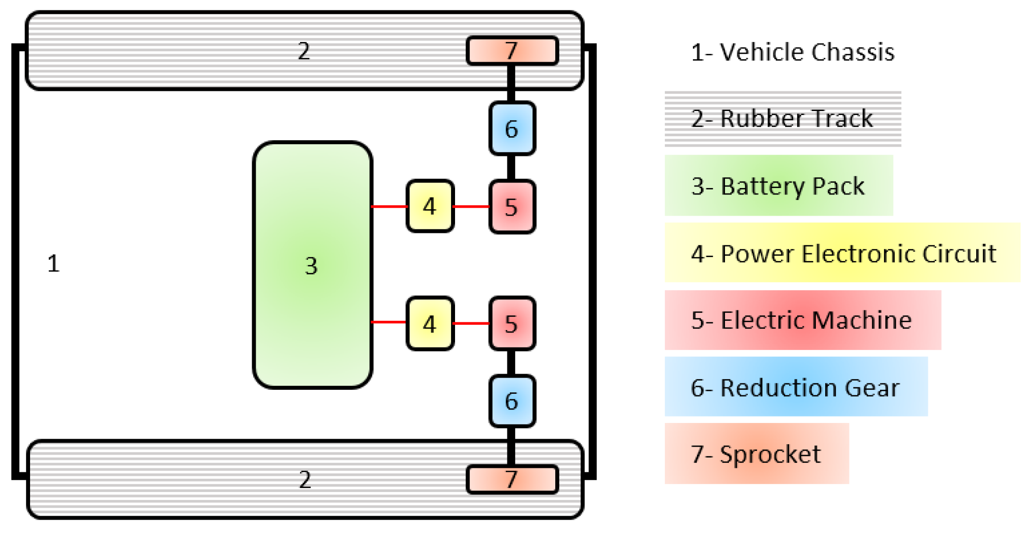
This study examined a self-driving, fully electric rubber-tracked vehicle known as the electric track vehicle. Figure 1 displays both the vehicle itself and the schematic of its prototype. The powertrain of this vehicle consists of several key components, including the battery, left and right electrical machines (EMs), power electronic converters (PEC), reduction gear, and sprocket. Additionally, Electronic Control Units (ECU) are also part of the powertrain, although they are not depicted in the figure for the sake of simplicity. The EM drivers facilitate the transfer of electric power between the electric machine and the battery pack. Furthermore, each motor supplies power to its respective sprocket through two speed-reduction gearboxes, which have a fixed gear ratio. This design enables the operator to effectively utilize the available power of the EMs while maneuvering through challenging terrains at slower speeds.
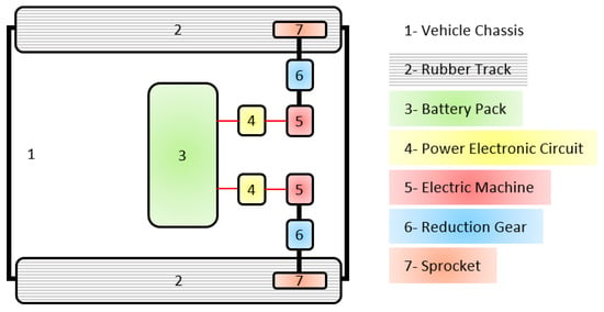
Figure 1.
The powertrain schematic of an electric tracked vehicle.
There are three primary factors to consider when modeling the power consumption of an electric drivetrain. These factors include the power losses of the electric motor (EM), power electronics converter (PEC), and mechanical transmissions. The losses in these components are influenced by various nonlinear effects stemming from environmental conditions, disturbances, and the nonlinear characteristics of the equipment. To investigate power consumption, researchers have proposed different modeling approaches, which can be found in the existing literature. In this particular study, the losses are determined using efficiency maps and formulation approaches based on the known characteristics of the equipment.
2.1.1. Power Electronics
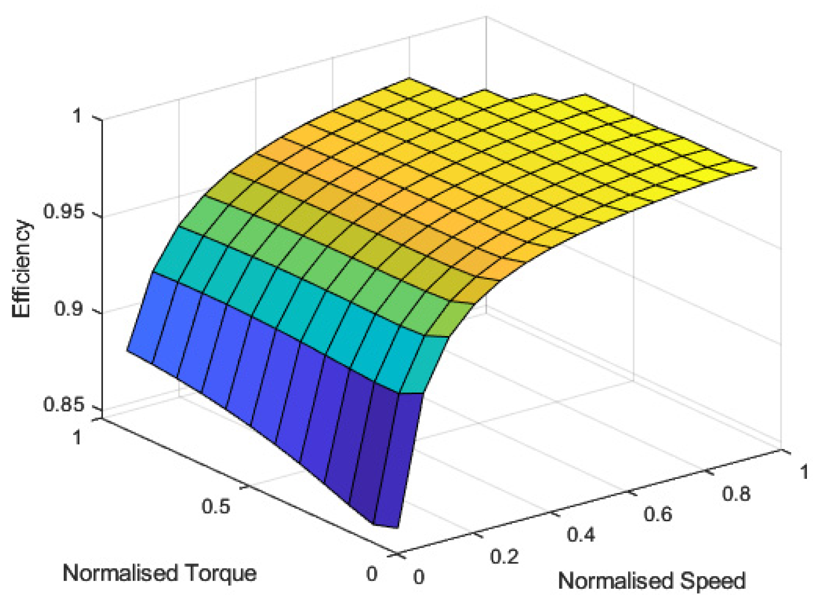
The power consumption of the PEC consists of the conduction and switching losses. Conduction losses are caused by the internal resistance of the switching device, whereas switching losses are due to the on–off characteristics of the current and voltage during switching. Hence, they are proportional to current, voltage, on–off times, and switching frequency. The efficiency maps of PECs both for the rear right and rear left EMs are shown in Figure 2. This figure is obtained from the 3D efficiency table composed by the supplier of the unit.
where is the efficiency of the power electronic converter; is the normalized electrical torque for each motor; is the normalized electrical torque required from the battery; is the normalized angular speed of the track; and are the total power on tracks of the vehicle and total required electrical power from the battery; and is the total energy usage from the battery between times and .
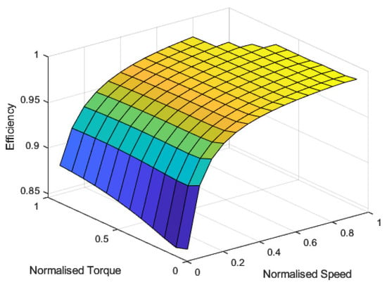
Figure 2.
Power electronic converter efficiency maps of both EMs.
2.1.2. Electric Machine
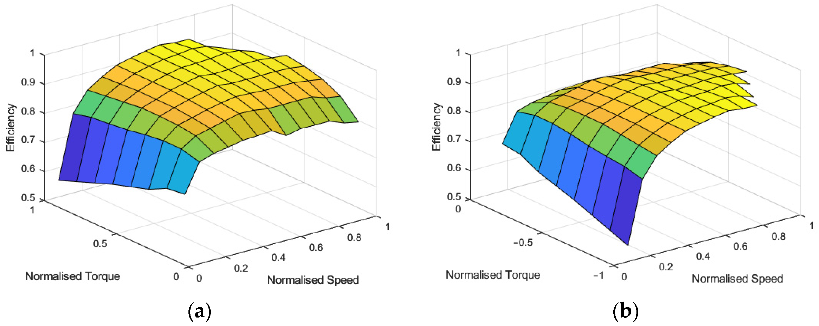
The onboard EMs are modeled using their torque versus speed characteristics and efficiency maps. The torque maps of both rear right and rear left EMs are given both for traction and braking in Figure 3. These figures are obtained from the 3D efficiency table composed by the supplier of the unit. Since both EMs are identical, the maps are presented only for one of the motors. Normalized torque and rotational speeds of both EMs were defined as inputs, whereas efficiency is defined as the output.
where is the efficiency of the electrical machine and is the normalized mechanical torque on the shaft of each motor.
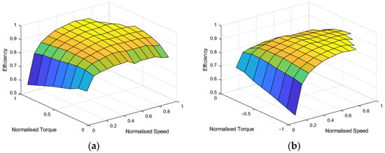
Figure 3.
Electric machine efficiency maps: (a) traction mode; (b) regeneration mode.
2.1.3. Transmission
There are two gears between the rubber track and the electric motor for each side of the vehicle. These gears are a reduction gear and sprocket. When the reduction gear reduces the rotational speed range of the motor output shaft, it increases the torque range for the sprocket. The main concern of the reduction gear is matching speed–torque needs for the motor and track of the vehicle. The purpose of the sprocket is to transmit the power of the motor to the vehicle track and it is also called a traction gear. The output speed and torque of the motor are divided and multiplied through the reduction gear ratio, respectively. After that, output torque and speed of the reduction gear are transmitted to the rubber track via the sprocket.
where and are total gear ratio and efficiency; is the torque in the rubber track; is the angular speed of the track; is the normalized power on the mechanical shaft of each motor; and and are normalization factors expressed as the maximum value of torque and speed, respectively. These parameters are obtained by multiplication of two gear parameters for efficiency and gear ratio terms separately.
where and are the gear ratio and efficiency of the reduction gear; and are the gear ratio and efficiency of the traction gear.
2.2. Dynamic Equations of Motion
The longitudinal vehicle dynamics of a tracked electric vehicle are modeled mathematically in this study to analyze the required torque, speed, power, and energy when driving a vehicle in the terrain. In this model, only longitudinal dynamics are considered. The external longitudinal forces acting on the moving vehicle are acceleration forces, , rolling resistance force, , aerodynamic drag force, , and hill-climbing force, , which resists the motion of the vehicle if going uphill and helps motion when going downhill. The dynamic model of a moving tracked electric vehicle with mass, , can be written as [35]:
where is the gravitational acceleration; is the friction coefficient; is the slope angle of the road; A is the maximum cross-section area of the vehicle; is the aerodynamic drag coefficient; is the air density; is the body speed of the vehicle; is the total force experienced by the vehicle; and r is the radius of the sprocket.
2.3. Terrain Model
To analyze the effect of the terrain on fuel consumption, the grade of the geographical formations is needed. For this purpose, ASTER GDEM highly accurate global digital elevation model is used. This map is generated and distributed by METI/NASA and available to all users. This map is int16 GeoTIFF consisting of 3601-by-3601 pixels for 1-by-1 degree of geographic latitude and longitude. The posting interval of the map is 30 m and the DEM accuracy is 7~14 m [36].
where , and are altitude differences, target, and current altitudes; , , , , and are flat distance, north and east co-ordinates of the target and current positions; γ, , and are the grade, the slope angle, and the 3D distance between the target and current positions, respectively.
2.4. Proposed Algorithm for Path Planning
The A* algorithm stands as a prominently favored solution for path-planning concerns within deterministic environments. Its advantageous attribute lies in its ability to efficiently generate a global path, offering a straightforward approach to establishing the shortest route between initial and final points. This algorithm implements a heuristic function, denoted as f‘(n)’, which serves as a cost estimation, aiding in its planning methodology.
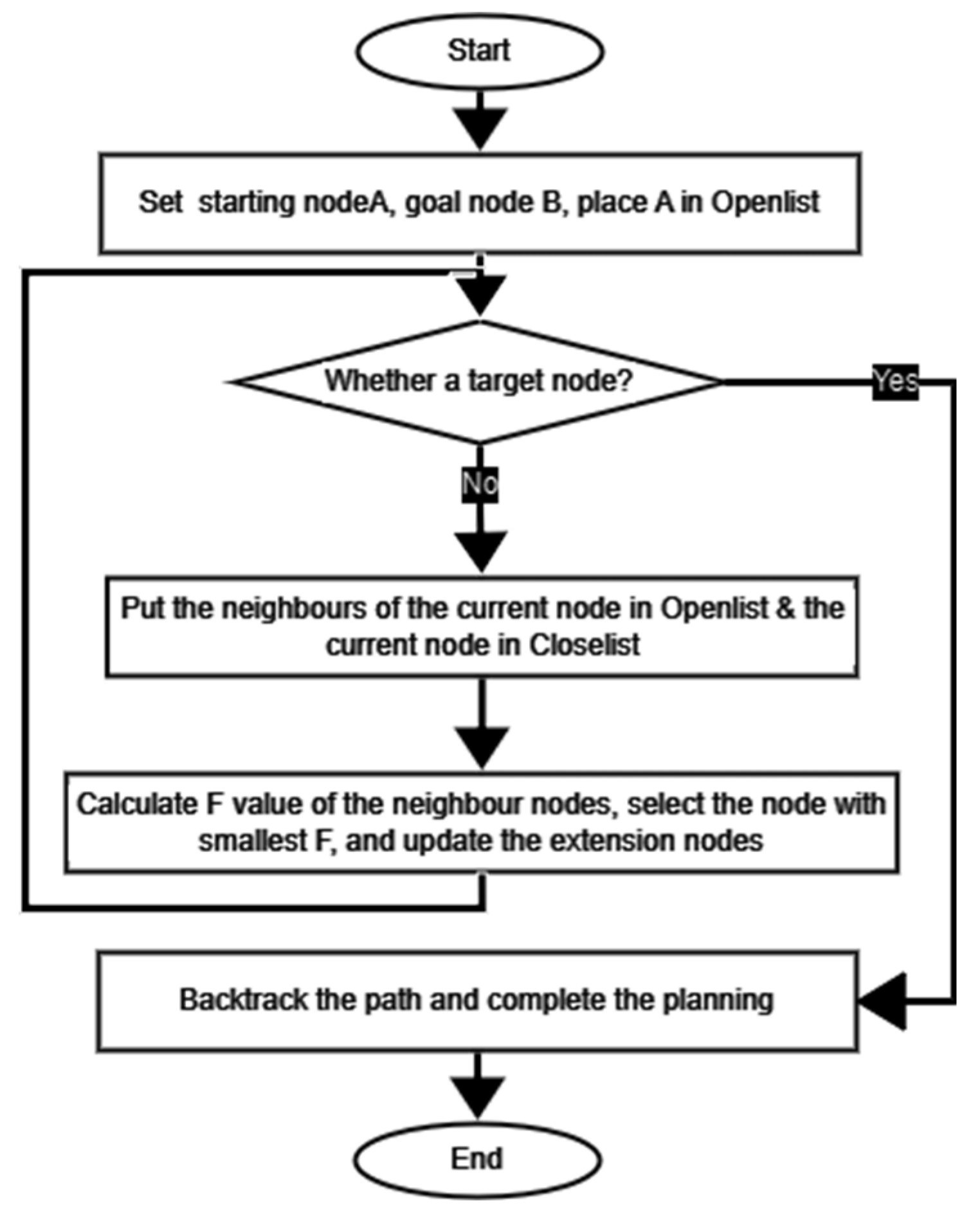
During the search process, the variable “n” represents a node or state. The expansion process of the A* algorithm is improved by considering both “g” and “h”, the range cost from the departure location to the current search location and the range cost from the current search location to the destination location, respectively. The algorithm’s objective is to reach the target node or detect search failure by opting for the search node with the lowest generation value for selection. This approach introduces a heuristic function, which adds purpose and direction to the expansion process, resulting in a more targeted and efficient path planning. As a result, the number of expanded nodes is reduced, improving the overall efficiency of the algorithm. Additionally, the A* algorithm offers the advantage of low computational overhead, making it a favorable choice for path-planning tasks. During the execution of the algorithm, two distinct lists were established. Openlist was implemented to serve as a repository for the locations that had been searched but not yet expanded, whereas Closelist was utilized to store the positions that had already undergone expansion. The sequential advancement of the algorithm’s implementation is visually depicted in Figure 4 [37].
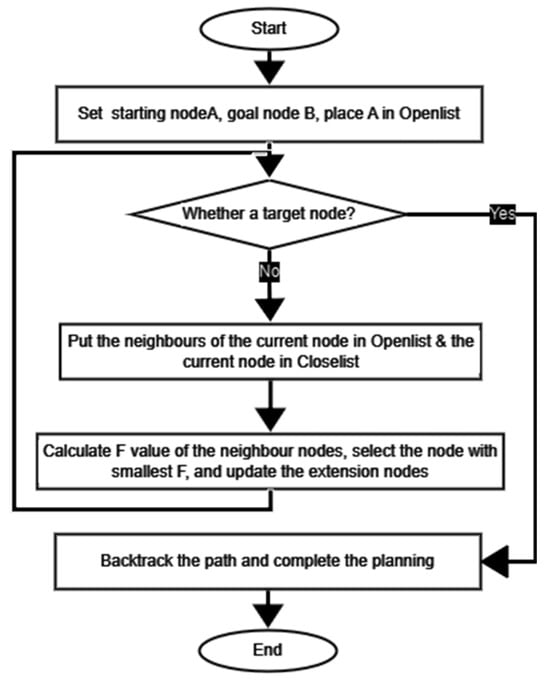
Figure 4.
Flowchart of A* algorithm.
In this study, the cost function of the classical A* is modified as an energy consumption model that consists of the acceleration, hill climbing, rolling resistance, and aerodynamic parts and e-powertrain efficiencies in the developed EEPP algorithm. In addition, system limitations are added to increase suitability for real-world applications.
where is a list containing the numbers of the selected nodes, respectively; c is the current node index; and k is the destination node index.
The range cost from the departure location to the current search location is obtained as in Equations (26)–(31).
where is the flat distance between previous node north-east co-ordinates, , and current node north-east co-ordinates, ; is the altitude difference between previous node altitude, , and current node altitude, ; and are the 3D distance and the grade between previous node north-east-altitude co-ordinates, , and current node north-east-altitude co-ordinates, ; is the power needed to go from the previous node to the current node and obtained from the dynamic energy consumption model as a function of the grade and the average body speed of the vehicle.
where is the flat distance between destination node north-east co-ordinates, , and current node north-east co-ordinates, ; is the altitude difference between destination node altitude, , and current node altitude, ; and are the 3D distance and the grade between destination node north-east-altitude co-ordinates, , and current node north-east-altitude co-ordinates, ; is the heuristic power needed to go from the current node to the destination node and obtained from the dynamic energy consumption model as a function of the grade and the average body speed of the vehicle.
As a result, cost function J can be defined as the sum of the energy cost from the departure location to the current search location and the energy cost from the current search location to the destination location, as in Equation (38).
In addition, the vehicle constraints can be given as in Equations (39)–(41).
3. Energy Consumption Model Validation
The validation of the proposed energy consumption model with real test vehicle data is crucial to understand the fidelity of this study. In this study, the Barkan-tracked electric vehicle developed by Havelsan was used. This vehicle on the test site can be seen in Figure 5.

Figure 5.
Images of the test vehicle from the test site.
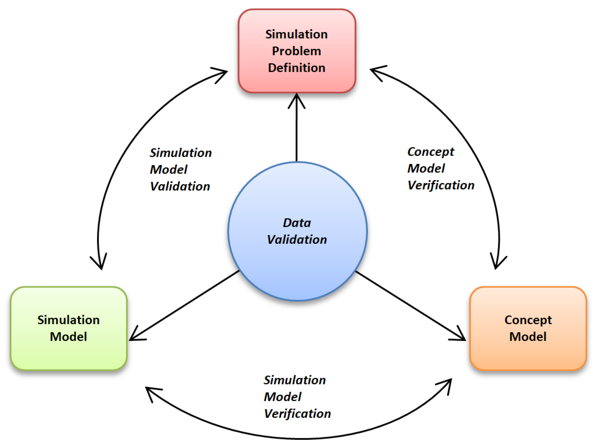
Three distinct phases of model verification and validation are illustrated in Figure 6. The first phase, known as conceptual model verification, aims to ensure that the conceptual model accurately reflects the simulation problems identified in the real-world system. This step is crucial in establishing the foundation of the model and ensuring its accuracy. The second phase, simulation model verification, focuses on confirming that the computer-based simulation model possesses sufficient accuracy to represent the conceptual model. This step involves assessing the model’s ability to accurately simulate the real-world system and its dynamics. It is essential to ensure that the simulation model faithfully represents the conceptual model to obtain reliable results. The final phase, simulation model validation, involves a series of simulation experiments that aim to confirm the accuracy, effectiveness, and efficiency of the model in understanding real-world problems [38].
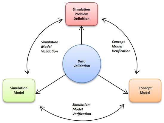
Figure 6.
Validation strategy for the energy consumption model [38].
In the context of the study, the self-validation and co-validation strategies, given in [38], were employed to verify and validate the simulation model concerning the energy consumption and dynamic characteristics of the vehicle. The simulation model serves the purpose of forecasting the performance of a system, enabling a comparison between the actual system performance and the predicted performance from the model. This comparison aims to ascertain whether the two are identical or sufficiently similar. By applying these strategies, it can be ensured that the simulation model accurately represents the energy consumption and dynamic characteristics of the vehicle.
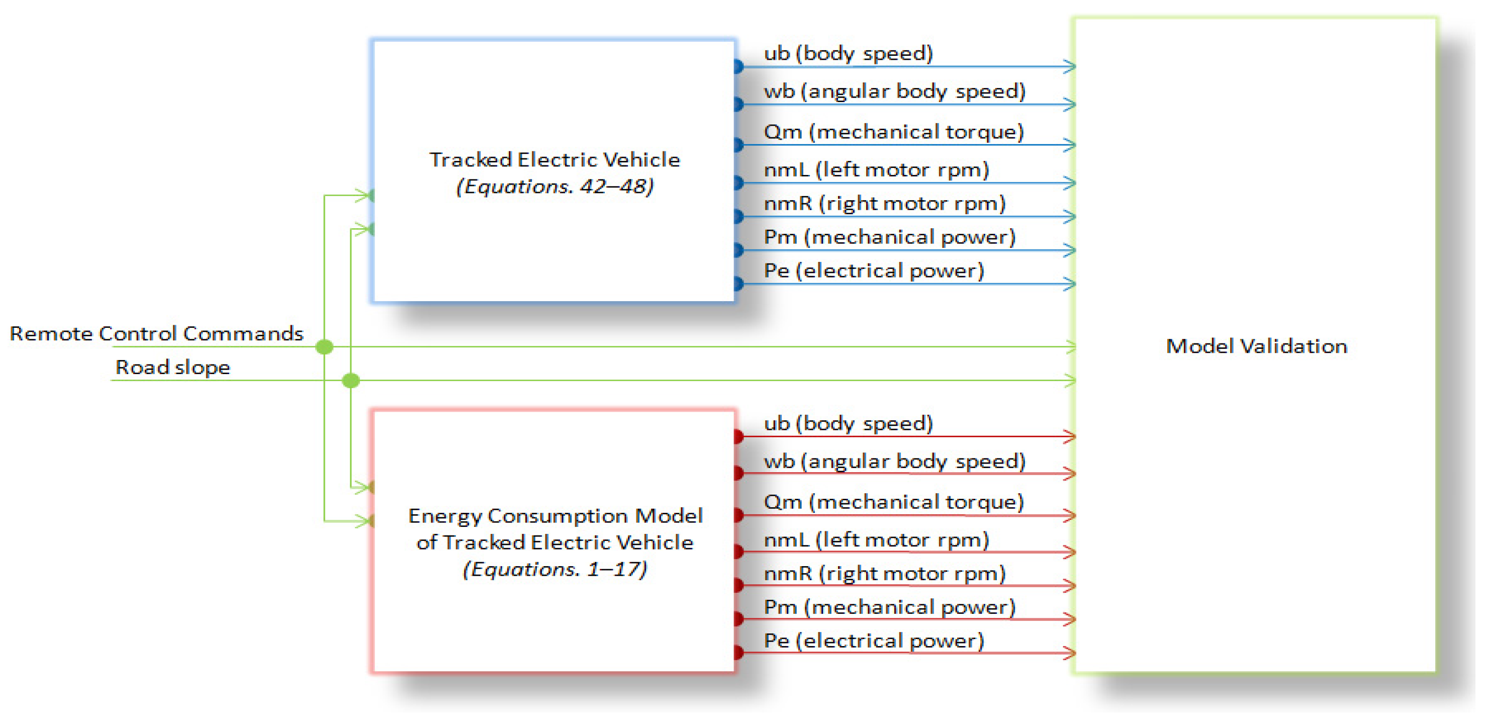
where , , and are north, east, and down speeds of the local NED frame, respectively; , and are roll, pitch, and yaw angles, respectively; is the body angular velocity; and are angular rates about y-axis and z-axis, respectively; , , and are total, right, and left motor torques; and are angular velocity of motors; and are produced mechanical shaft power of the motors and electrical required power for motors; and are the battery currents for right and left drives; and is the battery voltage. The characteristic of the validation methodology for the energy consumption model is shown in Figure 7.
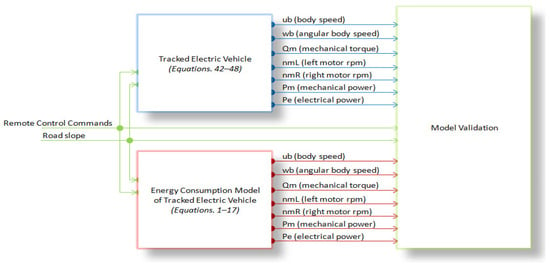
Figure 7.
Characteristic of the validation methodology for the energy consumption model.
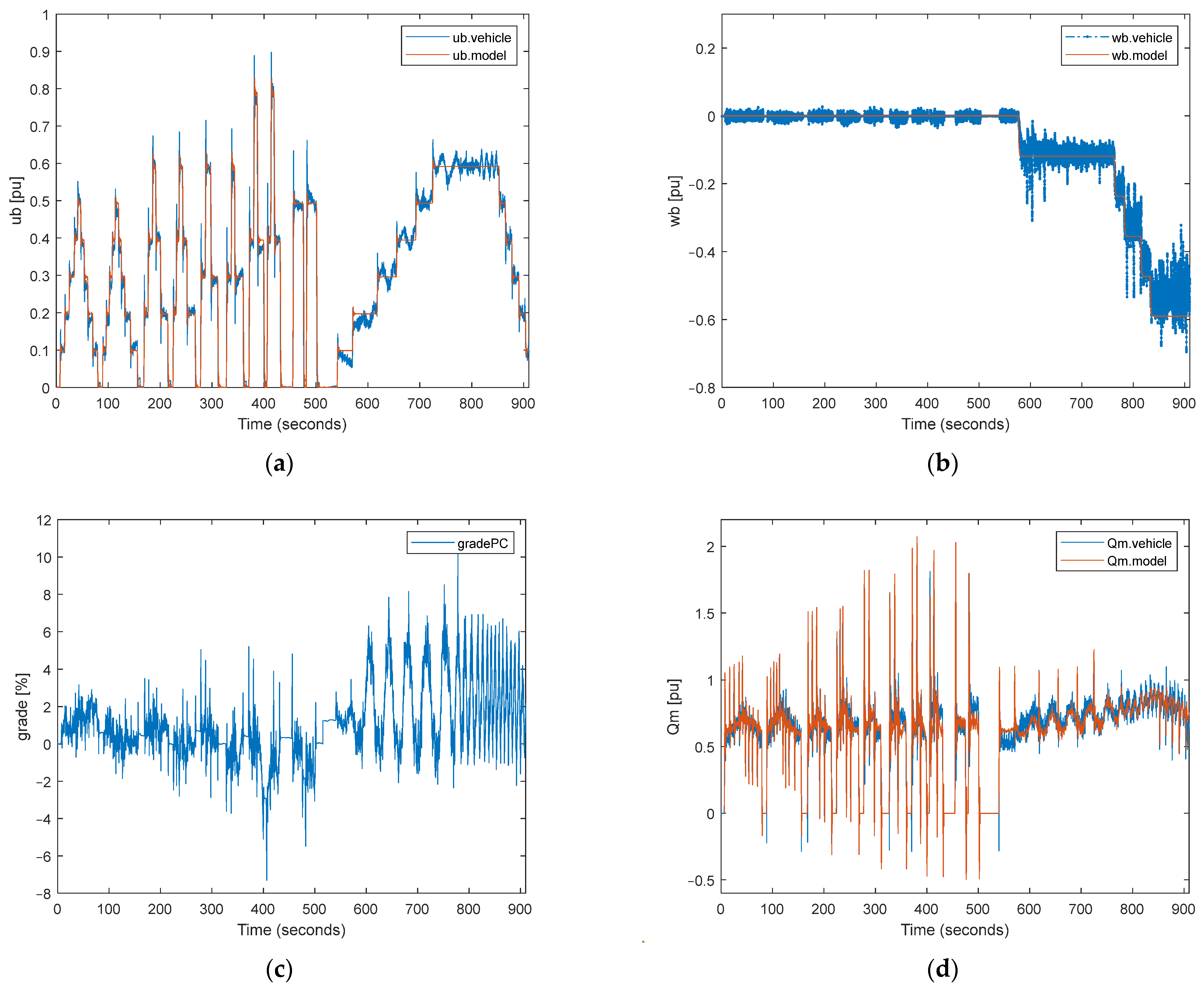
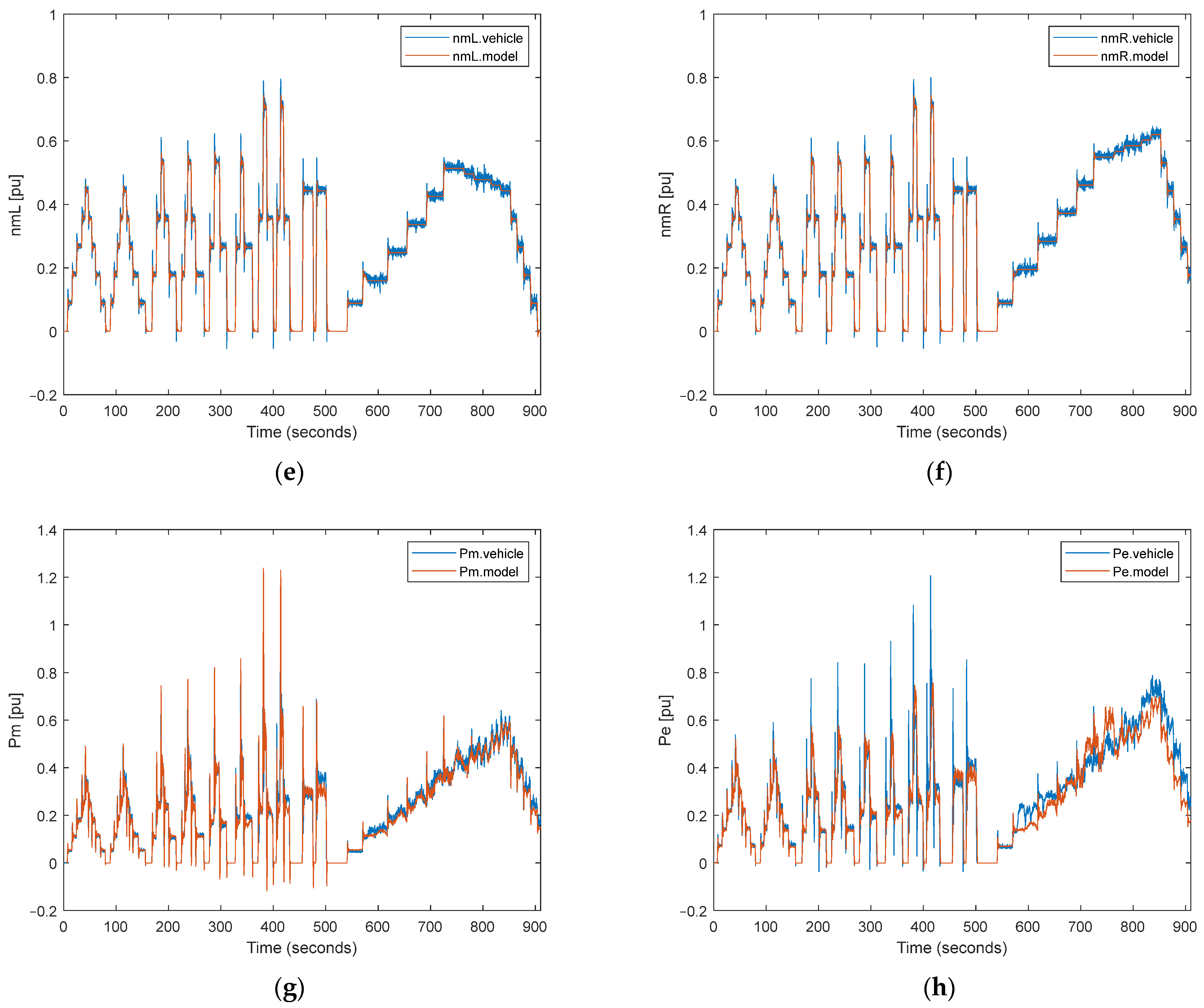
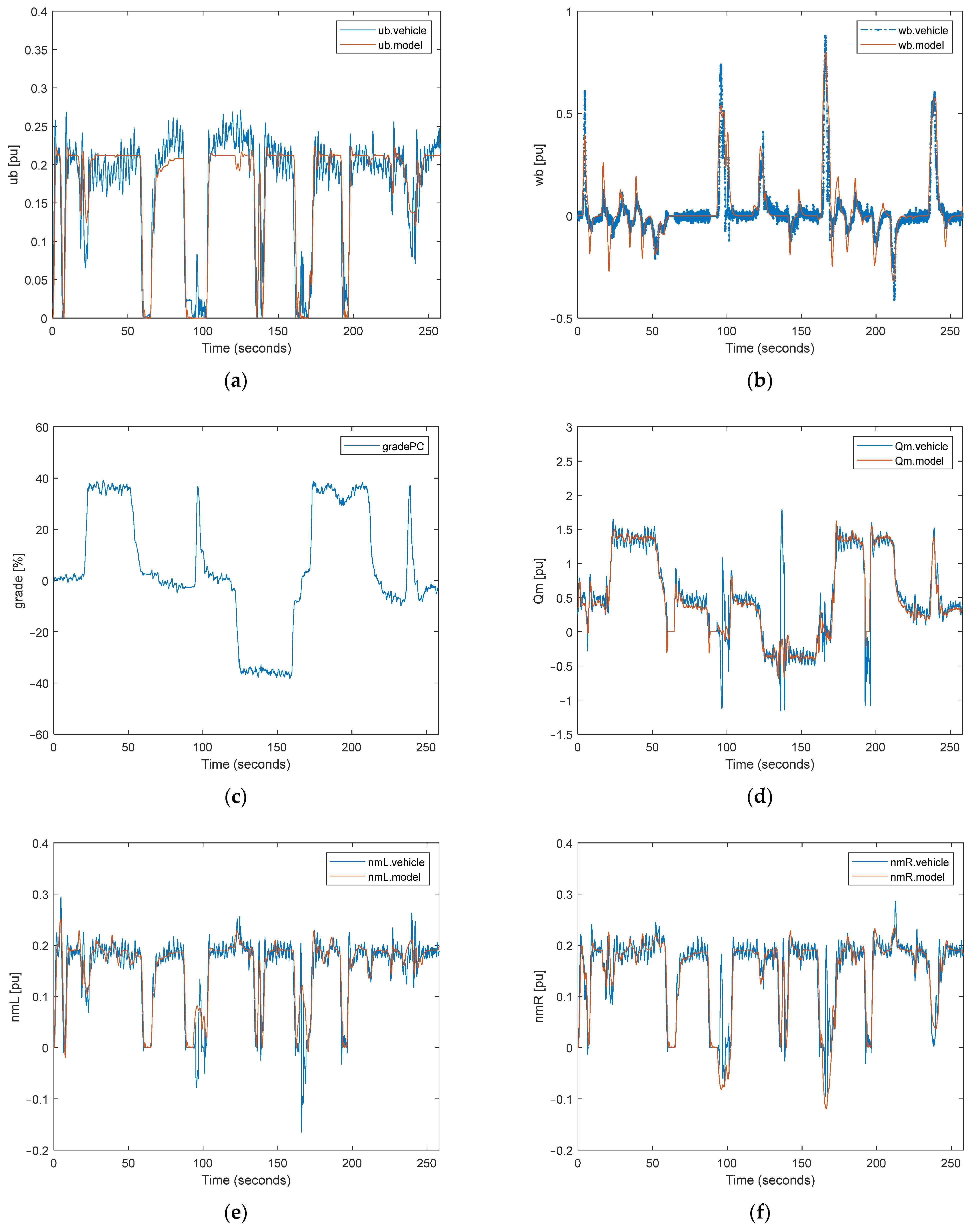
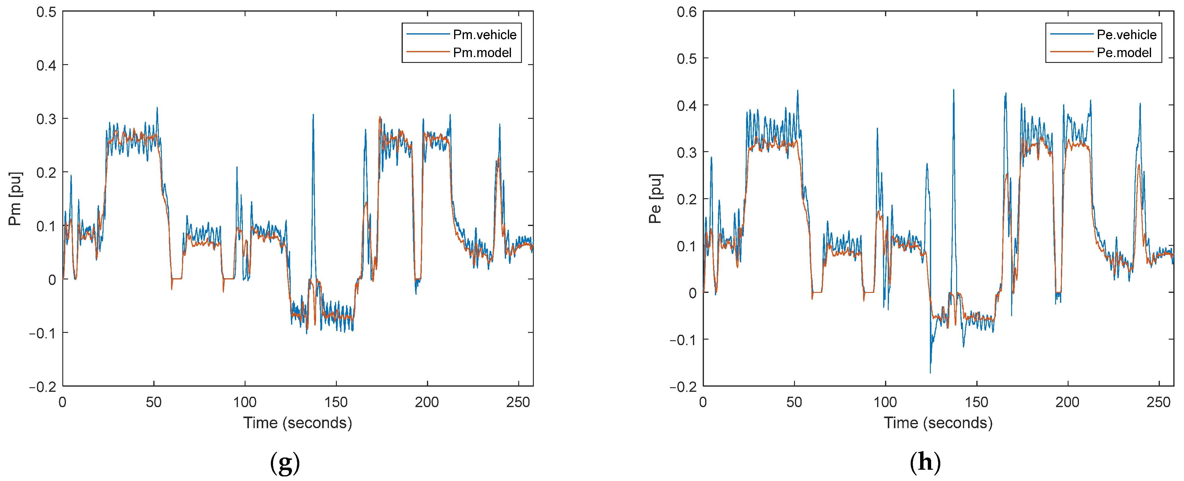
In the validation process of the system, two different driving tests were performed. The first test includes longitudinal and steering maneuvering, shown in Figure 8, and the second test outputs show maneuvering in the high-grade terrain, shown in Figure 9.
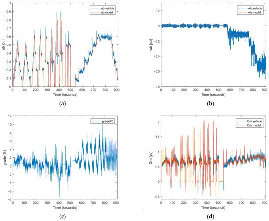
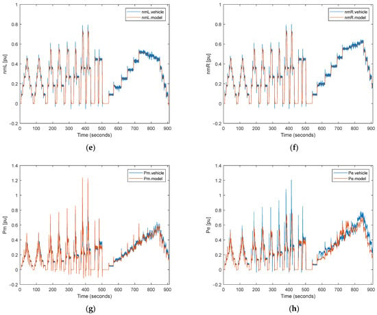
Figure 8.
Comparison of the simulation outputs and real test data for changing speeds and angular velocities: (a) vehicle speed; (b) vehicle angular velocity; (c) terrain grade percent; (d) motor torque; (e) left motor speed; (f) right motor speed; (g) mechanical power of the motor; (h) electrical power of the motor.
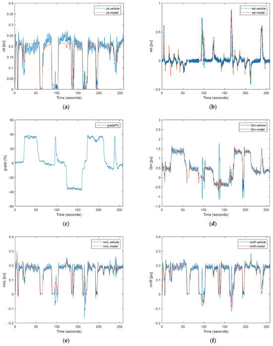
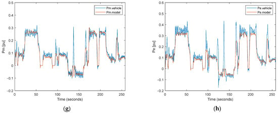
Figure 9.
Comparison of the simulation outputs and real test data for maneuvering in high-grade terrain: (a) vehicle speed; (b) vehicle angular velocity; (c) terrain grade percent; (d) motor torque; (e) left motor speed; (f) right motor speed; (g) mechanical power of the motor; (h) electrical power of the motor.
It is considered that the speed and angular speed of the vehicle calculated using commands applied to the system and the grade of the terrain are base inputs in Figure 8 and Figure 9a–c for our calculation method, as can be seen in Section 2. After that, this base input is used to calculate the torque, speed, and power of the motor shaft in Figure 8 and Figure 9d–g. Finally, the necessary electrical power obtained from the battery is calculated using efficiency maps drawn in Figure 8 and Figure 9h. In this study, figures are drawn per unit because of the confidential issues for military applications and the defense industry.
In general, a very good overlap was achieved in speed, torque, and power values. In regions where the overlap is slightly separated, it is thought that there is the effect of noncontinuous momentary disturbances originating from the system and the environment. As seen from the model and real test data, the performance of the overlap is achieved not only in steady-state behavior but also in transient-state behavior. The performance of the overlap is evaluated using the root mean square of the error (RMSE) shown in Table 1. All parameters are evaluated on a per-unit basis.

Table 1.
RMSE values comparison between model and real vehicle outputs.
In this study, the grade performance of the energy consumption model is investigated in off-road terrain. Therefore, in the second test, it was attempted to obtain the effect of the slope on speed, torque, power, and energy by using the tracked electric vehicle manually on a highly inclined road. Considering that we do not take into account the noise on the real system and other subsystem disturbances when the driving outputs on highly inclined roads and the model outputs are examined together, it has been determined that very similar results can be obtained with this model on inclined roads.
4. Energy-Efficient Path-Planning Simulation Results and Comparative Analysis
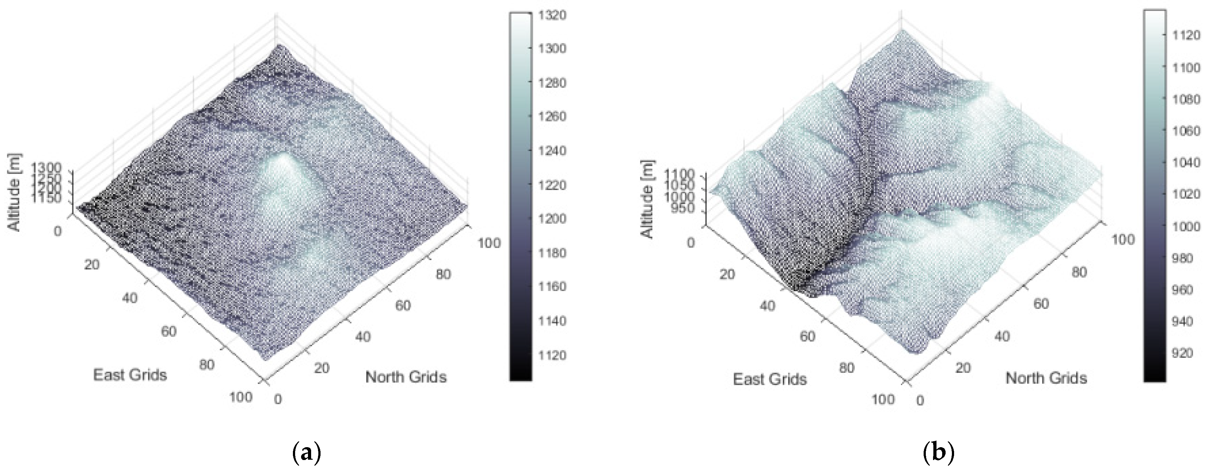
In this study, various off-road terrains and their impact on energy consumption are analyzed to validate the effectiveness of the solution using a validated energy consumption model of the tracked electric vehicle. Two different parts of Central Anatolia, approximately between N39E033 and N40E034 latitudes and longitudes, were used as terrain samples, seen in Figure 10, to analyze the effect of the terrain-validating algorithm performance. This land was carefully selected for its expansive steppe terrain, which boasts an abundance of route options. The decision to choose this area was primarily influenced by the near absence of obstacles, particularly vegetation, allowing for virtually limitless possibilities when planning routes and traversing the landscape.
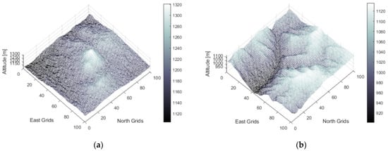
Figure 10.
Digital elevation models: (a) terrain A; (b) terrain B.
A path plan strategy was proposed tailored for an off-road tracked electric vehicle dynamic energy consumption model. To evaluate the success of the proposed algorithm, different routes are forced to be produced by changing the energy consumption model operation speed.
After that, energy consumptions on produced paths are compared using a validated energy consumption model of the tracked electric vehicle. This means that finding the energy-efficient path depends very much on the vehicle and vehicle dynamic energy consumption model created.
In terrain A and terrain B, reference paths are generated using the classical A* algorithm that tries to find the closest path and does not care about energy consumption. To ensure its applicability and comparability in real-world scenarios, the classical A* algorithm has been subjected to vehicle constraints. Energy-efficient paths are planned with the EEPP algorithm using a validated energy consumption model.
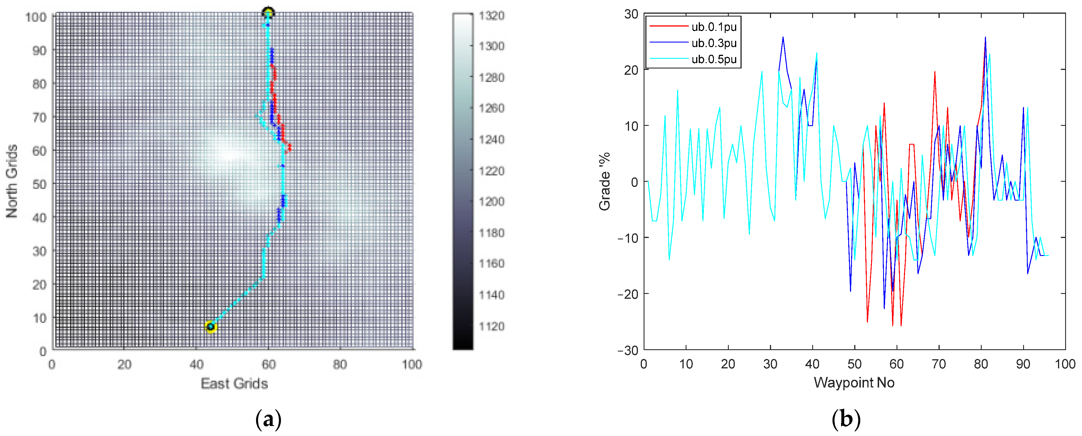
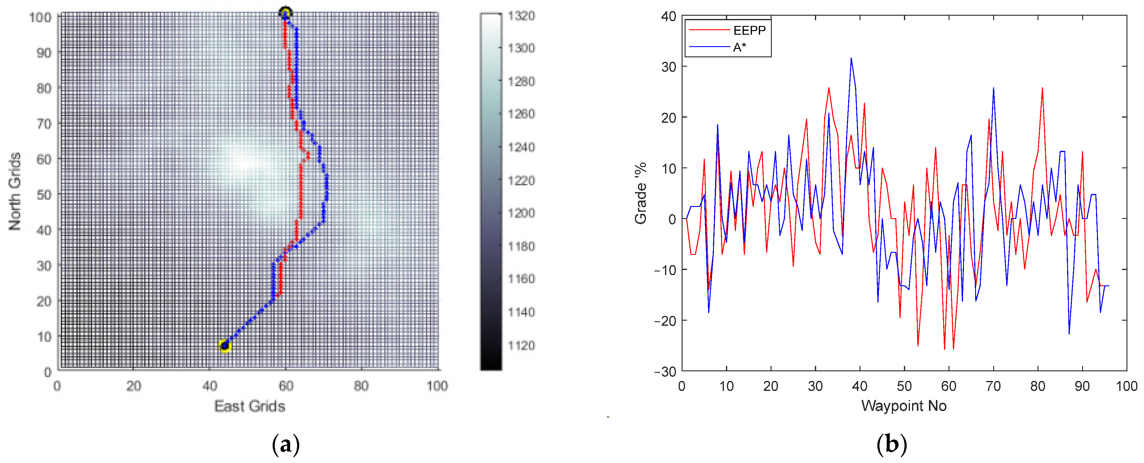
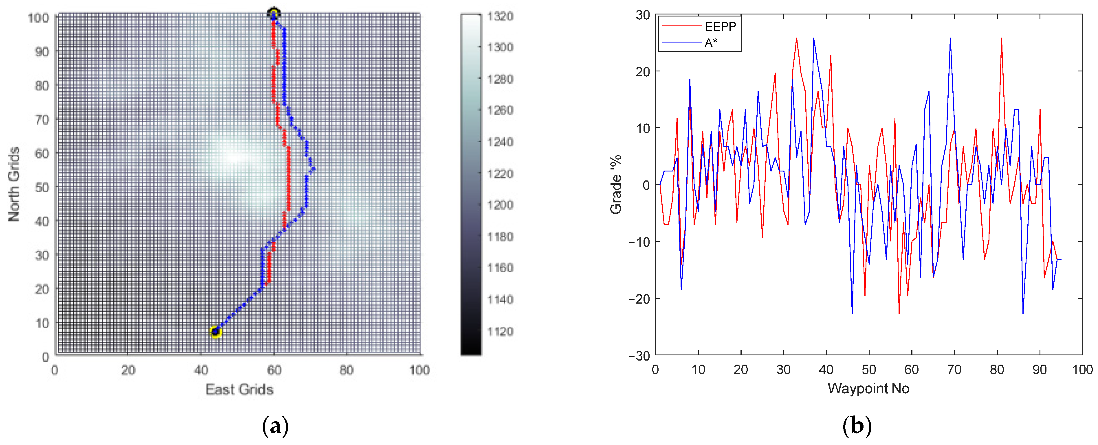
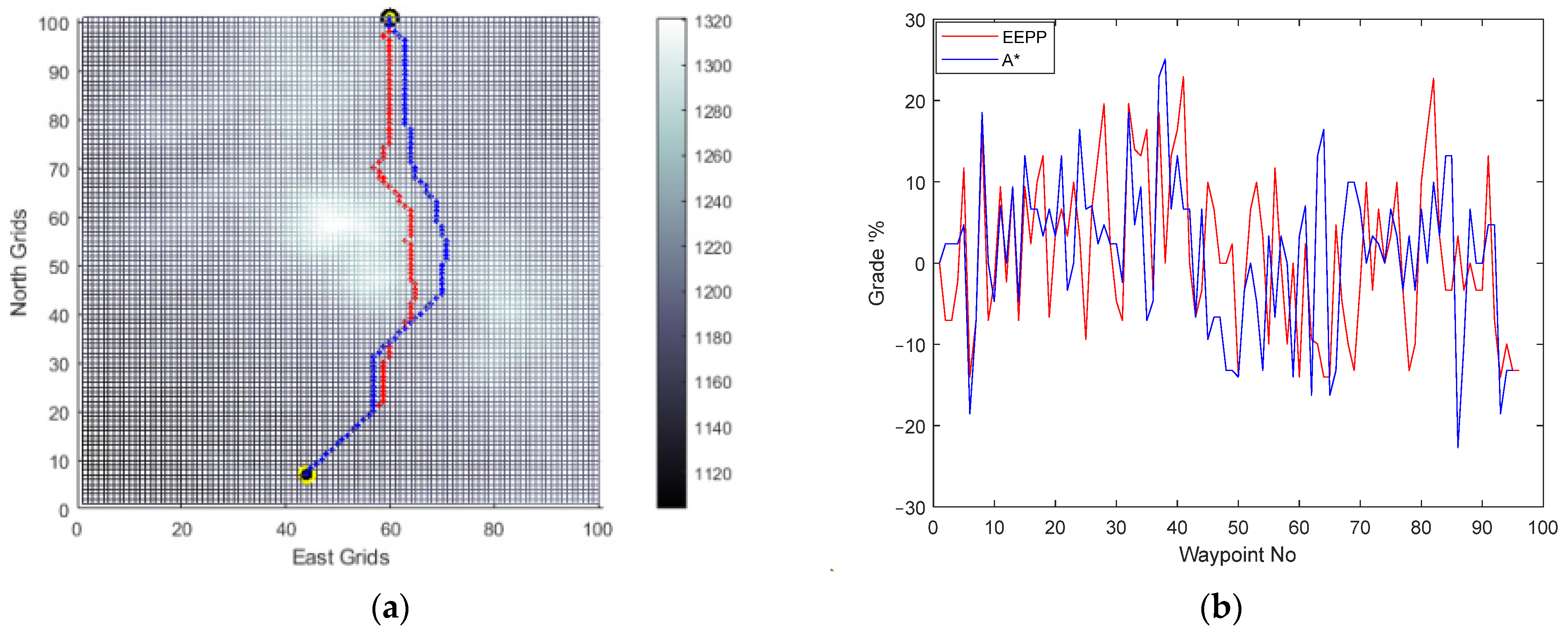
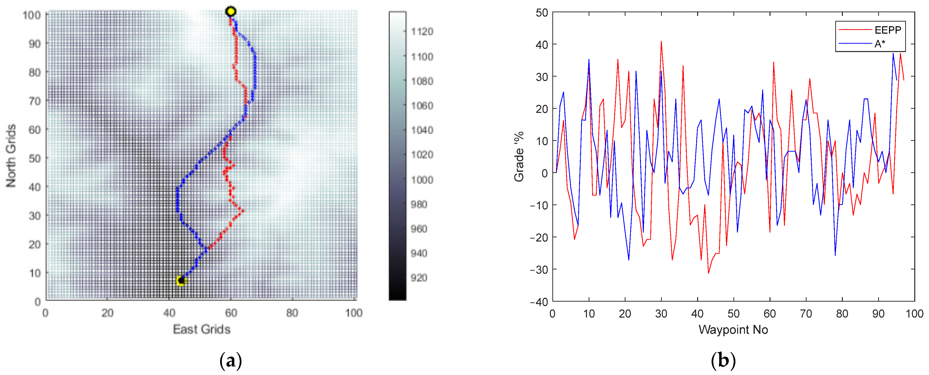
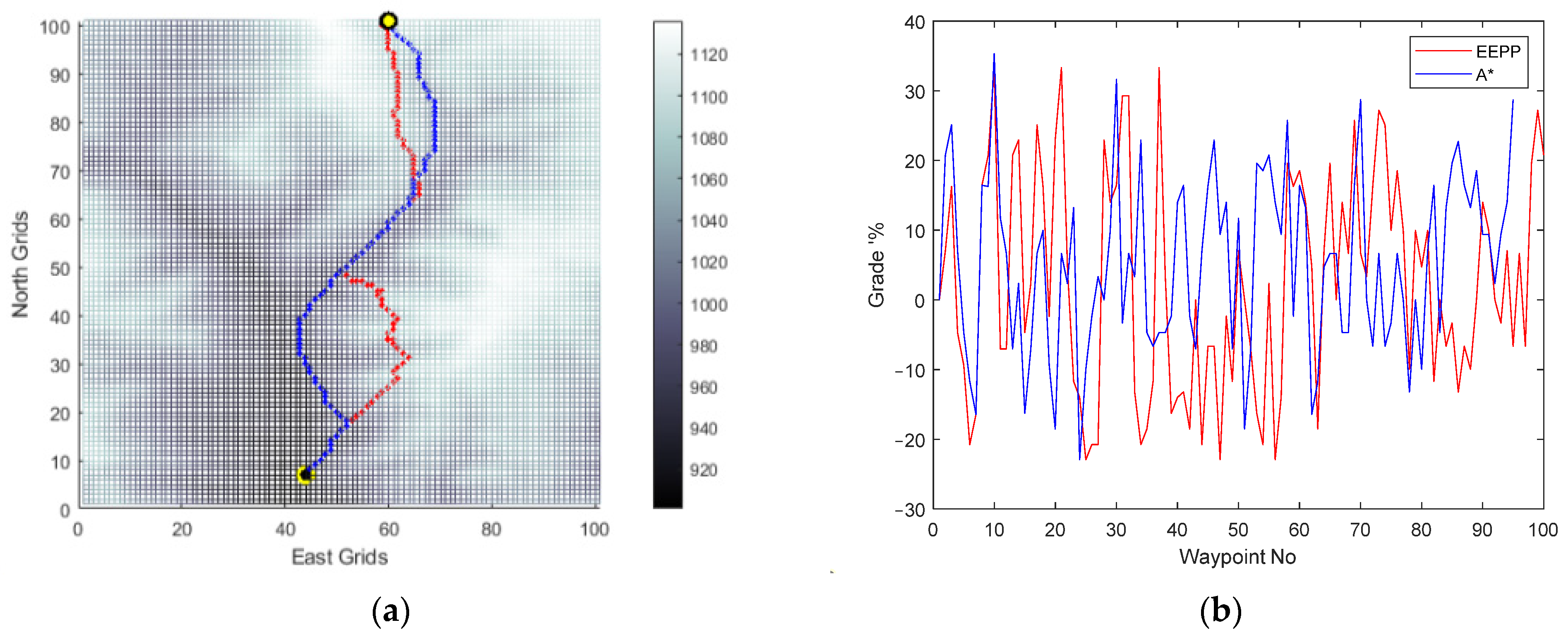
Firstly, to compare the effect of the body speed of the vehicle, the EEPP approach is also tried for different speeds of the vehicle on terrain A and presented in Figure 11, Figure 12, Figure 13 and Figure 14.
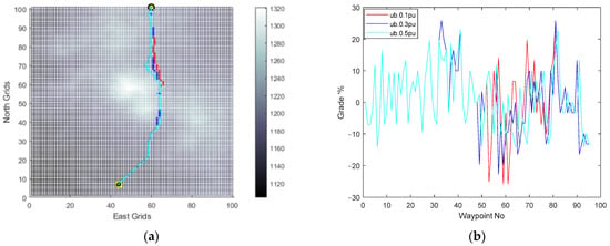
Figure 11.
(a) EEPP paths; (b) grades of the paths for changing speeds: 0.1 pu (red), 0.3 pu (blue), and 0.5 pu (cyan) on terrain A.
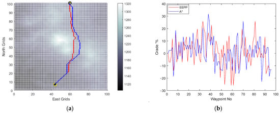
Figure 12.
(a) Generated paths A* (blue) and EEPP (red); (b) grades of the paths for speed of 0.1 pu on terrain A.
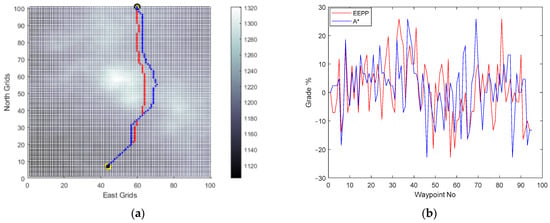
Figure 13.
(a) Generated paths A* (blue) and EEPP (red); (b) grades of the paths for speed of 0.3 pu on terrain A.
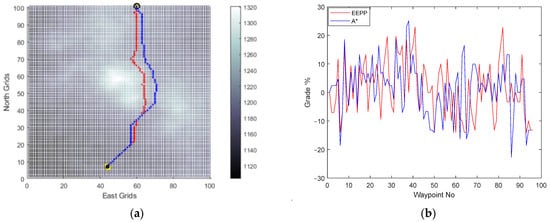
Figure 14.
(a) Generated paths A* (blue) and EEPP (red); (b) grades of the paths for speed of 0.5 pu on terrain A.
It was observed that adjusting the operational speed led to changes in the shapes of the paths generated within the system’s constraints. The incline conditions of the terrain were identified as a crucial factor influencing this alteration, mainly due to the vehicle’s ability to climb slopes. Furthermore, the simulation results confirmed the selection of the option with the lowest energy consumption among the available choices for reaching the same destination.
Horizontal positions of the waypoints and grade percent values of the routes are compared for paths generated by A* and EEPP for different vehicle speeds.
During the comparison process, focus is placed on the velocity of the vehicle, the duration of duty, the distance of the path generated, the energy utilized, and the steepest incline of the road traversed, which are then consolidated in the Table 2.

Table 2.
Comparison of the generated paths for Terrain A.
The utilization of the proposed algorithm enables the identification of a secure and cost-effective path in scenarios where the platform encounters difficulties in adhering to task constraints. It has been ascertained that relying solely on the analysis of terrain slopes and elevation maps fails to yield routes that are both energy-efficient and compatible with platform operation constraints. The efficacy of determining routes based on land slopes in terms of energy efficiency is inadequate. The tabulated data demonstrate that the designed path-planning method achieves energy savings of up to 6.93%. Consequently, this approach facilitates a 7.45% increase in the vehicle’s operational range. In addition, for Terrain A, no route was found that met vehicle constraints at speeds greater than 50% of the nominal vehicle speed.
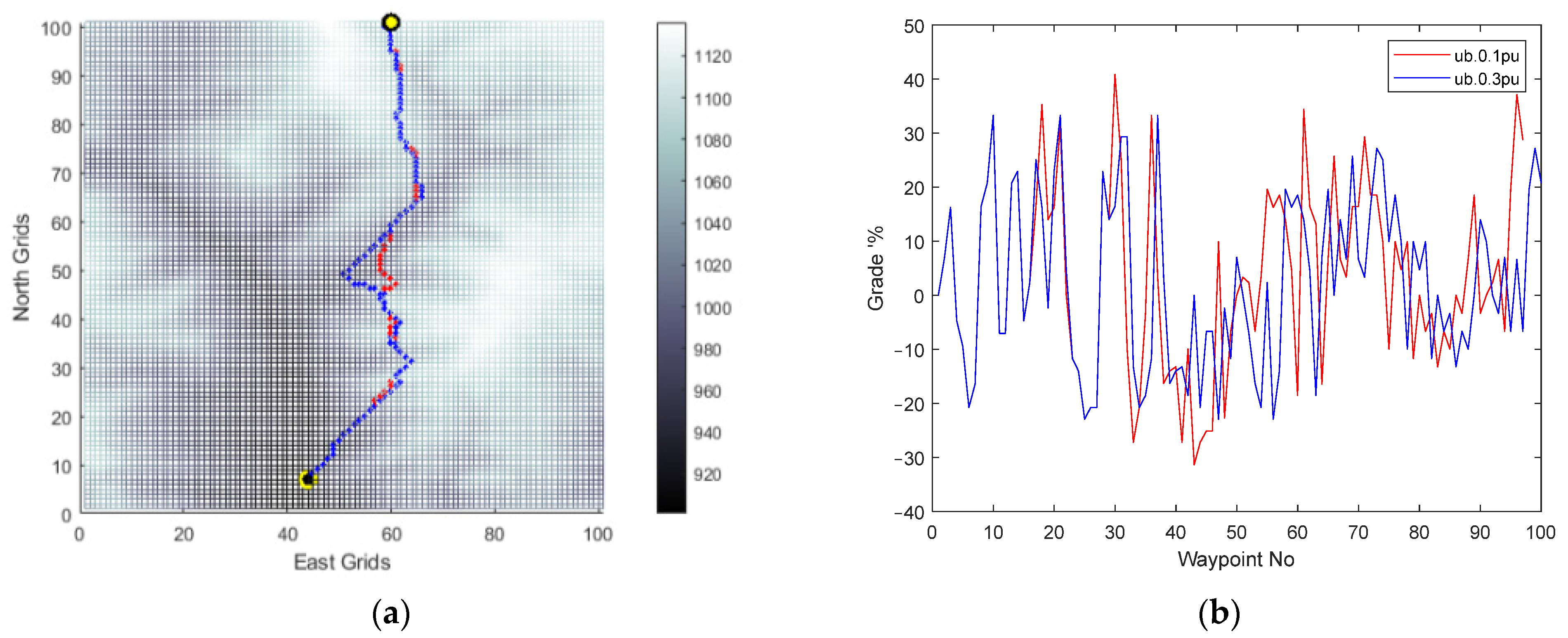
Secondly, to compare the effect of the body speed of the vehicle, the Energy-Efficient Path-Planning (EEPP) approach is also tried for different speeds of the vehicle on terrain B and presented in Figure 15, Figure 16 and Figure 17.
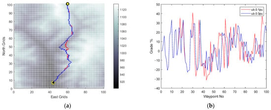
Figure 15.
(a) EEPP paths; (b) grades of the paths for changing speeds: 0.1 pu (red) and 0.3 pu (blue) on terrain B.
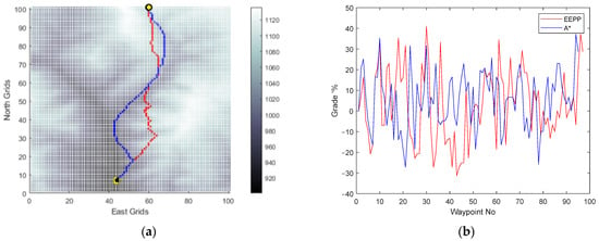
Figure 16.
(a) Generated paths A* (blue) and EEPP (red); (b) grades of the paths for a speed of 0.1 pu on terrain B.
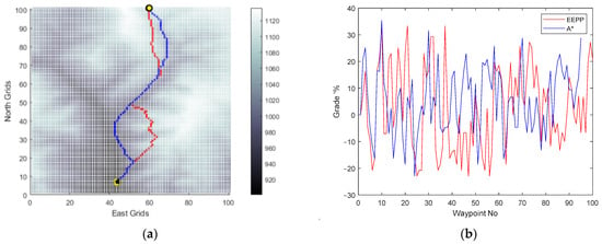
Figure 17.
(a) Generated paths A* (blue) and EEPP (red); (b) grades of the paths for a speed of 0.3 pu on terrain B.
The modification of the operational speed was observed to have an impact on the shapes of the paths generated within the system’s limitations. The incline conditions of the terrain were identified as a significant factor in influencing this alteration, primarily due to the vehicle’s capability to ascend slopes. Moreover, the simulation results validated the selection of the option with the lowest energy consumption among the available alternatives for reaching the same destination.
A comparison between the horizontal positions of the waypoints and the grade percent values of the routes was performed for paths generated by A* and EEPP at different vehicle speeds.
Throughout the process of comparison, attention is directed towards the speed of the vehicle, the length of time spent on duty, the distance covered, the energy consumption, and the maximum gradient of the road traveled, all of which are subsequently compiled in the Table 3.

Table 3.
Comparison of the generated paths for Terrain B.
The implementation of the suggested algorithm allows for the discovery of a secure and cost-efficient route in situations where the system faces challenges in meeting task requirements. It has been observed that relying solely on the examination of terrain slopes and elevation maps does not result in routes that are both energy-saving and in line with platform operation limitations. The effectiveness of selecting routes based on land slopes for energy efficiency purposes has been deemed insufficient. The data presented in the tables indicate that the proposed path-planning technique leads to energy conservation of up to 4.66%. As a result, this method enables a 4.88% enhancement in the vehicle’s operational capacity. Moreover, for terrain B, no viable route was identified that adhered to vehicle restrictions at speeds exceeding 30% of the nominal vehicle speed.
5. Conclusions
In this study, we developed and evaluated an energy-efficient path-planning algorithm using real off-road terrain models, leveraging the precision of ASTER GDEM distributed by METI/NASA. Through comprehensive tests on an actual vehicle, including various longitudinal and steering maneuvers, we validated the accuracy of our energy consumption model across different scenarios, particularly emphasizing the impact of slope on energy usage.
Our proposed algorithm proved instrumental in identifying energy-efficient paths, highlighting the inadequacy of relying solely on terrain analysis based on slopes and elevation maps. The data illustrate significant energy savings of up to 6.93%, resulting in a commendable 7.45% increase in the vehicle’s operational range. Furthermore, our algorithm outperformed traditional A* algorithms in identifying efficient routes, even under vehicle speed constraints.
Furthermore, for terrain A and terrain B, no route was discovered that satisfied vehicle constraints at speeds exceeding 50% and 30% of the nominal vehicle speed, respectively. To achieve this benefit, it is essential to construct a precise energy consumption model. Conversely, there is a possibility of incurring an additional energy loss because of the truly distant model parameters.
The present study introduces a path-planning algorithm that is built upon the widely employed A* algorithm technique. This algorithm is specifically designed for utilization in remote control and planning computer systems. Further investigations in this field could focus on enhancing the path-planning process in on-board computers by incorporating online terrain models with high resolution, thereby achieving more dynamic energy consumption. Additionally, the implementation of energy-consumption-based deep learning and model predictive control methods could potentially reduce the instantaneous power usage of the vehicle during its mission.
Author Contributions
Conceptualization, T.T.İ., G.C. and A.E.H.; Data curation, T.T.İ.; Formal analysis, T.T.İ.; Investigation, T.T.İ.; Methodology, T.T.İ., G.C. and A.E.H.; Project administration, B.Y. and G.Ç.; Resources, T.T.İ., B.Y. and G.Ç.; Software, T.T.İ.; Supervision, G.C. and A.E.H.; Validation, T.T.İ.; Visualization, T.T.İ.; Writing—original draft, T.T.İ., G.C. and A.E.H.; Writing—review and editing, T.T.İ., G.C., B.Y., G.Ç. and A.E.H. All authors have read and agreed to the published version of the manuscript.
Funding
This research received no external funding.
Data Availability Statement
Data are contained within the article.
Conflicts of Interest
Authors Taha Taner İnal, Barış Yalçın, Gürkan Çetin were employed by the company Havelsan. The remaining authors declare that the research was conducted in the absence of any commercial or financial relationships that could be construed as a potential conflict of interest.
References
- European Commission. Emissions from Non-Road Mobile Machinery. Available online: https://single-market-economy.ec.europa.eu/sectors/automotive-industry/environmental-protection/non-road-mobile-machinery_en (accessed on 1 January 2024).
- Barriers to Battery Electric Vehicle Adoption in 2023. Available online: https://www.exro.com/industry-insights/barriers-to-battery-electric-vehicle-adoption (accessed on 1 January 2024).
- Balali, Y.; Stegen, S. Review of energy storage systems for vehicles based on technology, environmental impacts, and costs. Renew. Sustain. Energy Rev. 2021, 135, 110185. [Google Scholar] [CrossRef]
- Yu, C.J.; Chen, Y.H.; Wong, C.C. Path Planning Method Design for Mobile Robots. In Proceedings of the SICE Annual Conference, Tokyo, Japan, 13–18 September 2011. [Google Scholar]
- Hu, L.; Zhao, X.; Liu, W.; Cai, W.; Xu, K.; Zhang, Z. Energy benchmark for energy-efficient path planning of the automated guided vehicle. Sci. Total Environ. 2023, 857, 159613. [Google Scholar] [CrossRef] [PubMed]
- Zhu, G.H.; Lin, J.B.; Liu, Q.W.; He, H.W. Research on the Energy-Saving Strategy of Path Planning for Electric Vehicles Considering Traffic Information. Energies 2019, 12, 3601. [Google Scholar] [CrossRef]
- Soori, M.; Arezoo, B.; Dastres, R. Optimization of energy consumption in industrial robots, a review. Cogn. Robot. 2023, 3, 142–157. [Google Scholar] [CrossRef]
- Ibrahim, N.S.A.; Saprudin, F.A. Review on path planning algorithm for unmanned aerial vehicles. Indonesia. J. Electr. Eng. Comput. Sci. 2021, 24, 1017–1026. [Google Scholar] [CrossRef]
- Alanazi, F. Electric Vehicles: Benefits, Challenges, and Potential Solutions for Widespread Adaptation. Appl. Sci. 2023, 13, 6016. [Google Scholar] [CrossRef]
- Savitski, D.; Schleinin, D.; Ivanov, V.; Augsburg, K.; Jimenez, E.; He, R.; Sandu, C.; Barber, P. Improvement of traction performance and off-road mobility for a vehicle with four individual electric motors: Driving over icy road. J. Terramech. 2017, 69, 33–43. [Google Scholar] [CrossRef]
- Roshanianfard, A.; Noguchi, N.; Okamoto, H.; Ishii, K. A review of autonomous agricultural vehicles (The experience of Hokkaido University). J. Terramech. 2020, 91, 155–183. [Google Scholar] [CrossRef]
- Fawzy, N.; Habib, H.F.; Mokhtari, S. Performance Evaluation of Electric Vehicle Model under Skid Control Technique. World Electr. Veh. J. 2021, 12, 83. [Google Scholar] [CrossRef]
- Huang, H.; Zhai, L.; Wang, Z. A Power Coupling System for Electric Tracked Vehicles during High-Speed Steering with Optimization-Based Torque Distribution Control. Energies 2018, 11, 1538. [Google Scholar] [CrossRef]
- Everitt, A.; Wight, G.; Dagenais, M.A. Dynamic Load Allowance for Military Tracked and Wheeled Vehicles: Experimental Results. In Proceedings of the 2019 International Conference on Military Technologies (ICMT), Brno, Czech Republic, 30–31 May 2019; pp. 1–6. [Google Scholar] [CrossRef]
- Visser, R.; Stampfer, K. Expanding Ground-based Harvesting onto Steep Terrain: A Review. Croat. J. For. Eng. 2015, 36, 321–331. [Google Scholar]
- Ferrara, A.; Jakubek, S.; Hametner, C. Energy management of heavy-duty fuel cell vehicles in real-world driving scenarios: Robust design of strategies to maximize the hydrogen economy and system lifetime. Energy Convers. Manag. 2021, 232, 113795. [Google Scholar] [CrossRef]
- Puma-Benavides, D.S.; Izquierdo-Reyes, J.; Calderon-Najera, J.d.D.; Ramirez-Mendoza, R.A. A Systematic Review of Technologies, Control Methods, and Optimization for Extended-Range Electric Vehicles. Appl. Sci. 2021, 11, 7095. [Google Scholar] [CrossRef]
- Wu, X.; Huang, S.; Huang, G. Deep Reinforcement Learning-Based 2.5D Multi-Objective Path Planning for Ground Vehicles: Considering Distance and Energy Consumption. Electronics 2023, 12, 3840. [Google Scholar] [CrossRef]
- Szczepanski, R.; Tarczewski, T.; Erwinski, K. Energy Efficient Local Path Planning Algorithm Based on Predictive Artificial Potential Field. IEEE Access 2022, 10, 39729–39742. [Google Scholar] [CrossRef]
- Al-Ansarry, S.; Al-Darraji, S.A.; Honi, D.G. An Efficient Path Planning in Uncertainty Environments using Dynamic Grid-Based and Potential Field Methods. Iraqi J. Electr. Electron. Eng. 2023, 19, 90–99. [Google Scholar] [CrossRef]
- Ganganath, N.; Cheng, C.T.; Tse, C.K. A Constraint-Aware Heuristic Path Planner for Finding Energy-Efficient Paths on Uneven Terrains. IEEE Trans. Ind. Inform. 2015, 11, 601–611. [Google Scholar] [CrossRef]
- Saad, M.; Salameh, A.I.; Abdallah, S. Energy-Efficient Shortest Path Planning on Uneven Terrains: A Composite Routing Metric Approach. In Proceedings of the 2019 IEEE International Symposium on Signal Processing and Information Technology (ISSPIT), Ajman, United Arab Emirates, 10–12 December 2019; pp. 1–6. [Google Scholar] [CrossRef]
- Erke, S.; Bin, D.; Yiming, N.; Qi, Z.; Liang, X.; Dawei, Z. An improved A-Star based path planning algorithm for autonomous land vehicles. Int. J. Adv. Robot. Syst. 2020, 17, 1729881420962263. [Google Scholar] [CrossRef]
- Song, X.; Gao, J. A Multilevel Adaptive Path-Planning Model in Off-Road Environments. Appl. Sci. 2022, 12, 10706. [Google Scholar] [CrossRef]
- Min, H.; Xiong, X.; Wang, P.; Yu, Y. Autonomous driving path planning algorithm based on improved A* algorithm in an unstructured environment. Proc. Inst. Mech. Eng. Part D J. Automob. Eng. 2021, 235, 513–526. [Google Scholar] [CrossRef]
- Wang, P.; Liu, Y.; Yao, W.; Yu, Y. Improved A-star algorithm based on multivariate fusion heuristic function for autonomous driving path planning. Proc. Inst. Mech. Eng. Part D J. Automob. Eng. 2023, 237, 1527–1542. [Google Scholar] [CrossRef]
- Zhang, J.; Wu, J.; Shen, X.; Li, Y. Autonomous land vehicle path planning algorithm based on the improved heuristic function of A-Star. Int. J. Adv. Robot. Syst. 2021, 18, 17298814211042730. [Google Scholar] [CrossRef]
- Chen, J.; Tan, C.; Mo, R.; Zhang, H.; Cai, G.; Li, H. Research on path planning of three-neighbor search A* algorithm combined with artificial potential field. Int. J. Adv. Robot. Syst. 2021, 18, 17298814211026449. [Google Scholar] [CrossRef]
- Baras, N.; Dasygenis, M. UGV Coverage Path Planning: An Energy-Efficient Approach through Turn Reduction. Electronics 2023, 12, 2959. [Google Scholar] [CrossRef]
- Zhang, S.; Liang, H.; Zhao, P.; Li, Z.; Su, T. Reference Path Generation for Autonomous Driving in Off-road Environment. In Proceedings of the 2nd International Conference on Robotics and Control Engineering, Nanjing, China, 25–27 March 2022. [Google Scholar] [CrossRef]
- Abdulsaheb, J.A.; Kadhim, D.J. Classical and Heuristic Approaches for Mobile Robot Path Planning: A Survey. Robotics 2023, 12, 93. [Google Scholar] [CrossRef]
- Yang, L.; Qi, J.; Song, D.; Xiao, J.; Han, J.; Xia, Y. Survey of Robot 3D Path Planning Algorithms. J. Control Sci. Eng. 2016, 2016, 7426913. [Google Scholar] [CrossRef]
- Karur, K.; Sharma, N.; Dharmatti, C.; Siegel, J.E. A Survey of Path Planning Algorithms for Mobile Robots. Vehicles 2021, 3, 448–468. [Google Scholar] [CrossRef]
- Gass, S.I.; Harris, C.M. (Eds.) Near-optimal solution. In Encyclopedia of Operations Research and Management Science; Springer: New York, NY, USA, 2001; p. 555. [Google Scholar] [CrossRef]
- Saleem, A.; Liu, N.; Junjie, H.; Iqbal, A.; Hayyat, M.A.; Mateen, M. Modelling of an Electric Vehicle for Tractive Force Calculation Along With Factors Affecting the Total Tractive Power and Energy Demand. In Proceedings of the 2020 3rd International Conference on Computing, Mathematics and Engineering Technologies (iCoMET), Sukkur, Pakistan, 29–30 January 2020; pp. 1–5. [Google Scholar] [CrossRef]
- ASTER Global Digital Elevation Model. Available online: https://www.jspacesystems.or.jp/ersdac/GDEM/E/2.html (accessed on 1 December 2023).
- Ye, M.; Zhao, J.; Guan, Q.; Zhang, X. Research on eVTOL Air Route Network Planning Based on Improved A* Algorithm. Sustainability 2024, 16, 561. [Google Scholar] [CrossRef]
- Yin, C.; McKay, A. Model Verification and Validation Strategies and Methods: An Application Case Study. In Proceedings of the 8th International Symposium on Computational Intelligence and Industrial Applications; The 12th China-Japan International Workshop on Information Technology and Control Applications, Tengzhou, China, 2–6 November 2018. [Google Scholar]
Disclaimer/Publisher’s Note: The statements, opinions and data contained in all publications are solely those of the individual author(s) and contributor(s) and not of MDPI and/or the editor(s). MDPI and/or the editor(s) disclaim responsibility for any injury to people or property resulting from any ideas, methods, instructions or products referred to in the content. |
© 2024 by the authors. Licensee MDPI, Basel, Switzerland. This article is an open access article distributed under the terms and conditions of the Creative Commons Attribution (CC BY) license (https://creativecommons.org/licenses/by/4.0/).

