Abstract
The performance of an electric vehicle (EV) notably depends on an energy management controller. This study developed several energy management controllers (EMCs) to optimize the efficiency of EVs in real-time driving conditions. Also, this study employed an innovative methodology to create EMCs, efficiency maps, and real-time driving cycles under actual driving conditions. The various EMCs such as PID, intelligent, hybrid, and supervisory controllers are designed using MATLAB/Simulink and examined under real-time conditions. In this instance, a mathematical model of an EV with a switched reluctance (SR) motor is developed to optimize energy consumption using different energy management controllers. Further, an inventive experimental approach is employed to generate efficiency maps for the SR motor and above-mentioned controllers. Then, the generated efficiency maps are integrated into a model-in-loop (MIL)-based EV test platform to analyze the performance under real-time conditions. Additionally, to verify EV model, a real-time driving cycle (DC) has been developed, encompassing various road conditions such as highway, urban, and rural. Subsequently, the developed models are included into an MIL-based EV test platform to optimize the performance of the electric motor and battery consumption in real-time conditions. The results indicate that the proposed supervisory controller (59.1%) has a lower EOT SOC drop compared to the PID (3.6%), intelligent (21.5%), and hybrid (44.9%) controllers. Also, the suggested controller achieves minimal energy consumption (44.67 Wh/km) and enhances energy recovery (−58.28 Wh) under different real-time conditions. Therefore, it will enhance the driving range and battery discharge characteristics of EVs across various real-time driving conditions.
1. Introduction
Electric vehicle (EV) adoption has been identified as the most optimal strategy for mitigating air pollution and greenhouse gas (GHG) emissions. Despite the increasing scarcity of fossil fuels and the ever-growing demand for the same, it is crucial that the automotive industry moves toward more environmentally friendly approaches [1]. Hybrid electric vehicles (HEVs) and electric vehicles (EVs) have emerged as pivotal solutions for the current environmental hardships. EVs have several advantages such as negligible pollutants, high efficiency, and quiet driving experience with minimal environmental noise, with being battery powered being the main reason for this [2]. However, to make EVs more acceptable and feasible for daily life, more advancements are needed, particularly in range extension, battery, and motor technology. Thus, the development of EVs and the assessment of their performance remain significant areas of interest for both the automotive sector and the research community [3]. Moreover, it is crucial that the power required for propulsion must be analyzed under real-word operating conditions to evaluate EV performance and optimize the characteristics of the electric motor (EM), battery, controller, and converter. The actual operation of the vehicle is highly unpredictable, influenced by factors such as road conditions, energy consumption (EC), temperature, road grade, and driving behavior [4,5]. Therefore, standardized driving cycles (DCs) mandated by legislation are employed for EC assessments of EVs. Several DCs are used globally, which include the New European Driving Cycle (NEDC), the Worldwide Harmonized Light Vehicles Test Cycle (WLTC), the Federal Test Procedure (FTP), the Indian Modified Driving Cycle (IMDC), US06, etc. [6,7]. In the study conducted in [8], the Urban Dynamometer Driving Cycle (UDDC) and NEDC were used to explore the impact of temperature on EC; this study revealed optimal EC values of 1.547 kWh and 1.648 kWh, respectively. Additionally, another study [9] delved into the influence of the gearbox on the EC of EVs, finding that dual and continuously variable gearbox systems conserve more energy than single-gear transmissions. However, the energy usage of electric vehicles is primarily influenced by factors such as the dimensions of components, operational zones of powertrain elements (motor and battery), state of charge (SOC), driving distance, and so on. Addressing these issues requires an optimal modeling environment to enhance vehicle performance and EC under various real-time driving conditions. Also, ensuring the effectiveness of vehicle modeling and validation procedures requires considering critical design and control decisions. The EV propulsion system’s primary components include an electric motor (EM), battery, controller, and power converters. Various types of EMs, such as a brushless direct current (BLDC) motor, permanent magnet synchronous motor (PMSM), switched reluctance motor (SRM), and induction motor (IM), are employed in EV propulsion systems. The choice of EM and its associated controller significantly impacts EV performance. Therefore, to maximize performance and energy efficiency, considering performance needs, economic concerns, and the desired driving experience, appropriate motor and controller selection is crucial. As well, the practice of longitudinal vehicle platooning plays a crucial role in autonomous intelligent transportation systems by ensuring the maintenance of an optimal longitudinal spacing with preceding vehicles [10,11,12,13]. In this study, the SR motor has been chosen due to its beneficial characteristics, including high starting torque, efficiency, and power density. As a result, the creation of an effective energy management system (EMS) is a widespread priority, especially for EVs, aiming to distribute power demand efficiently while maintaining drivability and performance.
Presently, various energy management system (EMS) techniques aim to enhance electric vehicle (EV) performance across diverse real-time conditions; these include proportional–integral–derivative (PID) control, direct torque control (DTC), model predictive control (MPC), field-oriented control (FOC), fuzzy logic control (FLC), hybrid control, etc. These controllers can be characterized by their ability to achieve specific goals, such as minimizing energy consumption, optimizing dynamic responsiveness, and enhancing drivability. Although DTC offers superior torque control, especially for SR motors in EVs, it has drawbacks like torque and current ripples at low speeds, making it challenging to attain maximal vehicle performance and minimal energy consumption under real-time driving conditions [14,15]. To achieve high performance while maintaining the battery state of charge (SOC) around the desired value during depletion, the integration of DTC and FOC techniques into SR motors for EV propulsion is explored. However, using both controllers results in poor energy consumption and regenerative braking efficiency in various driving conditions [16]. Consequently, the model predictive control (MPC) approach is employed to minimize EV energy consumption in real-time driving scenarios, forecasting future EV behavior and identifying optimal operating conditions. Despite its high computational costs and the need for prior knowledge of future driving actions, MPC fails to set appropriate battery discharge limits in real-time driving circumstances due to the complexity of EV systems [17,18]. In contrast, the proportional–integral–derivative (PID) approach gains attention for implementing an optimal EMS in real-world driving scenarios due to its reliability, short processing time, and efficient memory resource utilization. This approach dynamically adjusts control signals to enhance EV efficiency and driving range under various conditions. Optimization of PID variables using particle swarm optimization (PSO) and the genetic algorithm (GA) has shown improved transient response under real-time driving circumstances [19]. An optimally adjusted PID controller aids in seamless transitions between diverse driving conditions, optimizing the recovery of energy during regenerative braking and improving the efficiency of the battery. Unlike traditional vector control approaches like DTC and FOC, the PID controller showcases its ability to reduce energy consumption (EC) and expand the operational range of electric vehicles (EVs) in dynamic situations. The tuning of PID parameters and energy preservation in unpredictable conditions is accomplished in [20] through the utilization of battery state-of-charge (SOC) feedback and vehicle velocity. Despite its advantages in precise tracking of desired speed and torque for smooth acceleration and deceleration, PID control may struggle with nonlinearities and uncertainties in EV systems, impacting battery state-of-charge (SOC) estimation accuracy. Due to these reasons, the tuning of PID parameters is difficult in various transient conditions. Hence, designers have turned to intelligent controllers such as the fuzzy logic controller (FLC) and neural network (NN) to enhance EV performance under unpredictable conditions [21,22]. According to the literature, in order to regulate the nonlinear operations of electric vehicles (EVs), fuzzy logic control (FLC) utilizes a rule base and membership functions that incorporate input and output variables under different conditions. The precise calibration of the membership functions and rule base enhances accuracy in responses under diverse dynamic conditions. As a result, a fuzzy logic controller (FLC) proves more effective than a PID controller across various attributes like energy consumption (EC), state of charge (SOC), regenerative efficiency, etc., under changing speed and load conditions [23]. Nevertheless, the nonlinear behavior of battery usage introduces multiple uncertainties into the battery SOC feedback system. Therefore, adjusting FLC settings to enhance electric vehicle (EV) performance becomes crucial, a topic that researchers have yet to fully address.
To tackle uncertainties in real-time battery state of charge (SOC) while driving, an innovative hybrid learning approach is proposed [24]. This method combines fuzzy logic control (FLC) and proportional–integral–derivative (PID) techniques to govern electric vehicle (EV) transient error responses in various scenarios. The FLC’s role is to adapt PID parameters based on suitable rules and membership functions. This fusion of FLC and PID controllers is considered a ground-breaking hybrid strategy for reducing energy consumption (EC) and enhancing battery performance in diverse transient conditions. It offers the advantages of both accuracy and robustness, potentially improving battery health and lifespan. Furthermore, the hybrid approach is employed to enhance the performance of electric vehicles (EVs) across diverse road conditions (urban, rural, and highway). This is achieved by incorporating feedback from battery state of charge (SOC), vehicle speed, driving behavior, and the direction of current flow (regeneration) [25]. While various hybrid control techniques have been applied in research studies to manage unknown parameters in nonlinear systems operating under limited conditions, their data-driven nature makes it challenging to establish suitable mathematical models for real-time driving situations. Neural networks (NNs) represent a type of control mechanism capable of adapting and learning through adjustments in neuron weights, sizes, relationships between layers, and activation functions [26]. However, the precision of neural network control relies on both the quality and quantity of training data, with longer training times and potential issues outside the training domain. Recognizing the limitations of relying solely on a single learning approach, the integration of multiple control strategies (FLC and NN) through hybridization holds promise for achieving greater efficiency in real-time conditions [27]. In this context, the adaptive supervisory self-learning controller (ASSC) emerges as a hybrid learning control approach, combining FLC’s reasoning mechanism with NN’s self-learning capability. NN improves the output decisions of the fuzzy inference system by defining optimal membership functions based on training data, aiming to enhance EV performance and minimize EC in real-time scenarios. The ASSC approach quickly reduces variations in speed, torque, and unfavorable chattering consequences under different conditions. Implementing a supervisory control technique improves the dynamic behavior of the EV concerning battery SOC, EC, battery C-rate, regenerative efficiency, etc. [28]. Hence, the ASSC proves to be a more efficient control strategy than FLC and NN for managing battery state-of-charge (SOC) fluctuations in real-time scenarios. Implementing a nonlinear ASSC strategy holds the potential to improve the utilization profile of the battery SOC in electric vehicles (EVs), thereby extending their operational range. The ASSC approach is implemented with an SR motor used in EV applications under real-time conditions. In this study, the complete process of design and performance evaluation is carried out using the model-in-the-loop (MIL) simulation. MIL simulation is typically more efficient and computationally straightforward as it involves defining system behavior using a mapped experimental response technique, rather than relying on numerical representations to illustrate the behavior of the SR motor, controller, and battery systems. A model-based calibration technique is used for the development of an efficient SR motor and controller maps. This procedure encompasses several stages, including the design of experiments (DOE), model fitting, optimization, and lookup table generation. In the generation of maps (lookup tables), the application of experimental design enables a systematic exploration of the effects of the SR motor and controller behavior under diverse conditions, while minimizing the number of necessary test cases. This DOE-based approach systematically examines the impact of the SR motor and controller behavior under various conditions, reducing the complexity, time, and expense associated with map development. As the EV field evolves, advancements in control strategies will continue to be pivotal in achieving greater energy efficiency, prolonged battery life, and enhanced driving experiences.
Nowadays, automakers all agree that an effective energy management system (EMS) is necessary for EVs to operate optimally under real-time driving conditions. This study emphasizes the significance of a sophisticated EMS in enhancing the energy efficiency of EVs under practical scenarios. The numerical simulation of EV performance using various EMS techniques in real-time driving situations has been the subject of numerous studies. Moreover, precisely determining the driving range through an assessment of electric vehicles’ EC is crucial in eliminating driver anxiety. However, identifying the optimal discharge path for EVs is challenging due to factors such as driving actions, road grade, travel distance, and initial SOC variability. This study aims to accomplish the goal of efficient energy management and battery utilization in EVs by introducing an advanced self-learning control strategy. The objective of this is to bridge the gap between theoretical advancements and practical implementation by evaluating the effectiveness of the optimal EMS in an SR motor-equipped EV under real-world driving conditions. Despite numerous studies on EV performance with different control methods, there is a lack of comprehensive publications examining the performance characteristics of EVs with various energy management approaches. In this context, the objective of the present study aims to develop a mathematical model of an EV by integrating a mapped SR motor and controller efficiency with different EMS techniques. This research paper introduces energy management strategies such as proportional–integral–derivative (PID) control, fuzzy logic control (FLC), hybrid control, and adaptive supervisory self-learning controllers (ASSCs) to minimize energy consumption and extend EV range under diverse operating conditions. The ASSC approach is found to enhance the dynamic behavior of EVs compared to traditional approaches like PID, FLC, and hybrid, considering parameters such as battery SOC, energy consumption, battery C-rate, and regenerative efficiency. A novel aspect of this work is the development of a real-time driving cycle in urban, rural, and highway conditions to assess the effectiveness of EVs in practical operating scenarios. Additionally, this research paper employs an innovative methodology to create DCs and efficiency maps of the controller and SR motor under real-time conditions. These maps are then incorporated into the EV model to evaluate various performance parameters, including energy consumption, regeneration efficiency, motor power, battery SOC, battery current, and C-rate, using different energy management controllers. This study concludes by comparing the performance of various energy management controllers (PID, fuzzy, hybrid, and ASSC) across the beforementioned parameters to validate the real-time performance superiority of the proposed adaptive supervisory self-learning controller. It is anticipated that the ASSC approach will significantly improve battery utilization, ultimately enhancing the real-time operational performance of electric vehicles. The specified objectives of this study aim to provide readers with knowledge and a critical perspective on the design and development of effective energy management controllers for electric vehicles while also suggesting potential areas for future research.
2. Proposed Methodology
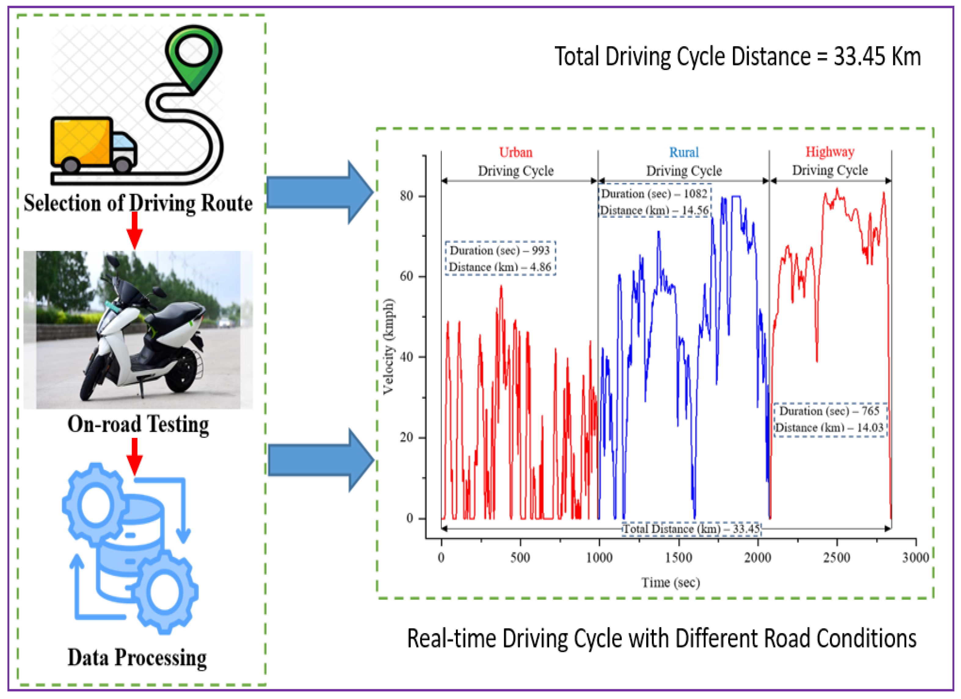
The methodology involves the usage of various energy management controllers with the integration of efficiency maps and a real-time driving cycle for different operating conditions to evaluate the performance of the EVs. In this study, the entire design and performance evaluation process is conducted using the model-in-the-loop (MIL) simulation. The workflow and proposed methodology are organized into four aspects, as illustrated in Figure 1. Using the parameters of Ather 450 plus the vehicle as a reference, the EV model is created with an SR motor using MATLAB/Simulink. Table 1 contains detailed specifications of the developed EV model. This study builds an electric vehicle configuration using a backward-looking modeling approach. It starts with sub-models for longitudinal blocks, transmission blocks, battery blocks, mapped motor blocks, and controller blocks. A real-time driving cycle and a variety of efficiency maps of energy management controllers (PID, FLZ, hybrid, and ASSC) are installed in the EV model in order to validate the performance of the EVs. Second, to guarantee the battery utilization path and extend the driving range of electric vehicles, this research work develops several energy management controllers, such as PID, FLZ, hybrid, and ASSC, under real-time operating conditions. Using a point-by-point model-based calibration technique, the motor and controller behavioral maps (lookup tables) are produced experimentally using various energy management controllers in transient scenarios. In order to assess the effectiveness of different energy management controllers under real-time operating conditions, a real-time DC covering a range of road situations, including urban, rural, and highway applications, is built. In order to confirm the performance of EC, regeneration efficiency, motor power, battery SOC, battery current, C-rate, etc., the created efficiency maps and DC are also loaded into the EV simulation model. On the other hand, depending on the initial battery SOC and trip distance, different battery usage characteristics apply. The battery utilization path is constant throughout real-time operation when the various energy management controllers are utilized to minimize sudden energy distribution, increasing the vehicle’s operating range. In order to ensure the superior real-time performance of energy management, a variety of performance characteristics are finally compared between the various energy management controllers. It is expected that the suggested ASSC approach will result in better battery utilization, which will eventually improve the operational performance of electric vehicles in real time.

Figure 1.
Proposed methodology of the present research.

Table 1.
Technical specifications of the developed electric vehicle.
3. Development of Two-Wheeler Electric Vehicle Model to Validate the Performance of the Proposed Control System
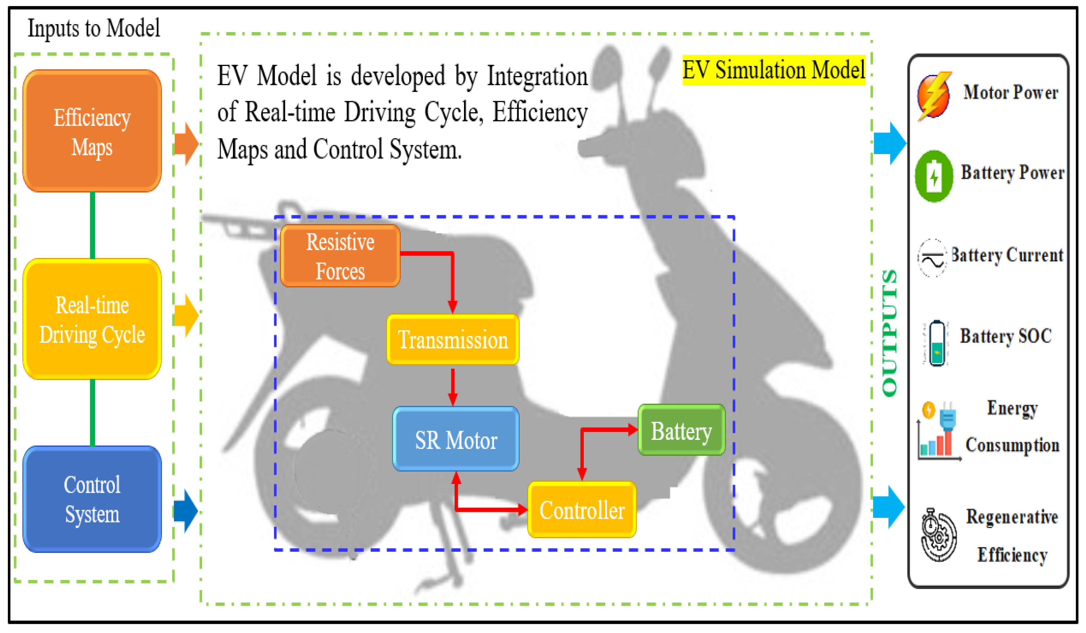
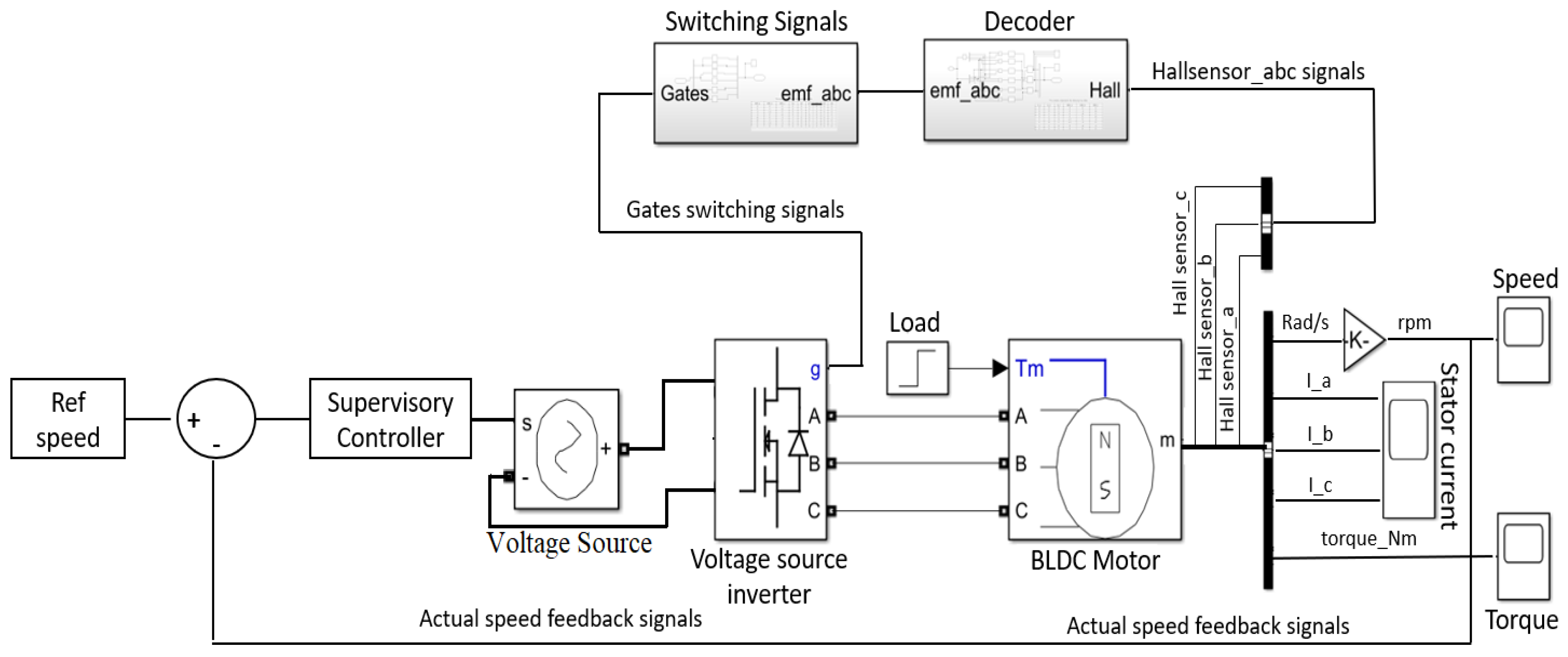
The development and analysis of a backward-facing Matlab–Simulink EV model with an SR motor arrangement are presented in this article. The schematic representation of the EV configuration is illustrated in Figure 2. The Simulink model consists of five essential functional blocks, each derived from the physical components incorporated into the electric vehicle (EV) system. These blocks include the longitudinal block, transmission block, battery block, mapped motor, and controller block. The architecture of the developed Simulink function block, designed for simulating the EV model, is illustrated in Figure 2. In this section, the significance and mathematical relationships governing the vehicle dynamics, battery, motor, and controller are analyzed to enhance the precision of energy consumption (EC) and driving range estimations.
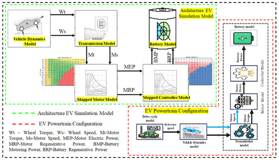
Figure 2.
Schematic representation of EV simulation model and EV powertrain configuration.
3.1. Longitudinal Vehicle Dynamics Model
Analysis of the dynamics and the impact of different parameters on the performance of the vehicle is the first step in the modeling process. The forces acting on the vehicle are determined to compute these parameters. The model is characterized by a single degree of freedom (DOF) focusing solely on longitudinal motion, with lateral and vertical motions being disregarded [29]. In the fundamental powertrain modeling, the evaluation of electric vehicle (EV) performance centers on its longitudinal dynamics. Longitudinal resistive forces, including aerodynamic force, acceleration force, rolling force, and gradient forces, are taken into account [30]. The driving cycle plays a pivotal role in the longitudinal vehicle dynamics block as it provides a critical input. This involves a comprehensive assessment of various resistive forces exerted on the vehicle during its longitudinal motion. These encompass rolling forces (Equation (1)), arising from the interaction between the tires and the road surface; aerodynamic forces (Equation (2)), influenced by the vehicle’s shape and speed; gradient forces (Equation (3)), stemming from inclines or declines in the terrain; and acceleration forces (Equation (4)), reflective of changes in velocity. After that, the estimation of the total tractive force is illustrated in Equation (5). Finally, the output of the longitudinal vehicle dynamic block is wheel speed and torque, as specified in Equations (6) and (7).
where: GVW—grass vehicle weight, GVM—grass vehicle mass, Crf—coefficient of rolling resistance, Fr—rolling force, Fa—aerodynamic force, Fg—gradient force, Facc—acceleration force, Ft—total tractive force, Cd—drag coefficient, Af—frontal area, a—acceleration, —density, Wt—wheel torque, Ws—wheel speed, Rw—wheel radius, and V—velocity (rpm).
3.2. Transmission Model
To cater to diverse EV tractive requirements, an effective power electronics-controlled SR motor is employed in EVs as a substitute for multi-speed transmissions, opting for gearless or single-speed gear transmission [31]. In the context of this study, the transmission model is structured around a single-speed transmission with a gear ratio of 7.8:1. It utilizes inputs from the longitudinal model, namely, wheel speed and torque, to estimate the motor speed and torque, which are then transmitted to the SR motor model. The outputs of the transmission model are articulated in Equations (8) and (9).
where: GR—gear ratio, Mt—motor speed, Ms—motor speed (rpm), and Teff—transmission efficiency.
3.3. Mapped SR Motor and Controller Model
The SR motor and controller’s operating range determines an EV’s acceleration, maximum speed, passing ability, and gradeability, among other performance metrics. However, integrating a mathematically modeled SR motor and controller into an EV simulation introduces an additional computational challenge and encapsulates the intricate dynamic features of the transient SR motor [32]. As a result, utilizing the steady-state empirical model of the SR motor and controller behavior, optimal response behavior maps are created. In the part that follows, the testing and map-building process will be thoroughly explained. In consideration of these factors, the developed SR motor and controller efficiency maps, incorporating different energy management systems (EMSs) such as PID, FLC, hybrid, and ASSC, are employed in the EV simulation model. Furthermore, based on inputs from the transmission model (Mt and Ms), the mapped SR motor model estimates motor mechanical power (MMP) (Equation (10)) and motor electrical power (MEP) (Equation (11)) under various real-time operating conditions. MEP is determined by integrating the efficiency maps of different energy management controllers for the SR motor. Additionally, the motor model calculates motor regenerative power (MRP) (Equation (12)) by incorporating the regenerative efficiency maps of different controllers under diverse operating conditions. Subsequently, to assess the performance of the mapped controller in real-time conditions, the outputs of the motor block (MEP and MRP) are transmitted to the controller block.
Here, Meff represents motor efficiency, S denotes motor speed, and T represents motor torque. The operations of the SR motor and battery are regulated by the controller. It determines any modifications in the vehicle’s operation related to energy demand based on signals received from the motor model block. The controller block integrates different motor controller and regenerative controller efficiency maps to estimate battery motoring power (BMP) and battery regeneration power (BRP) using inputs (MEP and MRP) from the motor block. Equations (13) and (14) express the functions. Ultimately, the battery block receives the outputs of the mapped controller block (BMP and BRP) in order to evaluate the energy consumption (EC) and regenerative efficiency of various control algorithms under the current operating conditions. Comprehensive details on the suggested control algorithms are provided in Section 4.
where: MCeff—motor controller efficiency, BMP—battery motoring power, and BRP—battery regenerative power.
3.4. Battery Model
The battery, being a complex and nonlinear system, presents challenges in modeling due to its dependence on SOC, temperature, aging, and internal resistance. Understanding the variations in and limitations of parameters related to battery performance is crucial under real-time driving conditions [33]. However, to simplify the battery model, this work does not delve into the study of the influence of battery aging and temperature. The lithium-ion battery is a common energy source in electric vehicles (EVs) due to its distinctive characteristics, including high voltage potential, high energy density, and being lightweight, with minimal self-discharge. Utilizing inputs (BMP and BRP) from the controller block, the battery model forecasts E/km, battery current, driving range, SOC, C-rate, and regeneration efficiency with different energy management controllers (PID, FLC, hybrid, and ASSC) in real-time driving cycles. The magnitude and direction of battery current in EVs vary based on the accelerator throttle and brake position. Additionally, battery SOC serves as a direct indicator of the total available energy in the battery during trips, a crucial factor in evaluating the remaining driving range of EVs. Furthermore, the overall driving range of EVs is directly associated with the energy consumed and recovered during acceleration and braking. This dependence is primarily influenced by atmospheric conditions, road segment characteristics, vehicle physical parameters, speed, and acceleration. Lastly, the functional equations describing E/km and SOC are provided in Equations (15) and (16).
where: BMP—battery motoring power, ISOC—initial SOC, Bc—battery current, and Bcap—battery capacity.
4. Design and Development of Efficient Control Systems to Evaluate the Performance of Two-Wheeler Electric Vehicles
An effective energy management controller increases EV range and efficiency while decreasing EC under a variety of operating circumstances. This study looks into several energy management controllers, such as PID, fuzzy, hybrid, and supervisory, to improve EV performance in real-time driving scenarios. Under a range of dynamic conditions, these controllers can accurately forecast the battery utilization route while minimizing EC and enhancing regeneration efficiency. In order to develop efficiency maps for the motor and controller, these controllers are built and tested (steady-state experimentation) in a variety of dynamic situations. Various energy management controllers are used to develop efficiency maps for the motor and controller in real time. The experimental technique and development of the control system for the SR motor are explained in the following parts.
4.1. PID Controller
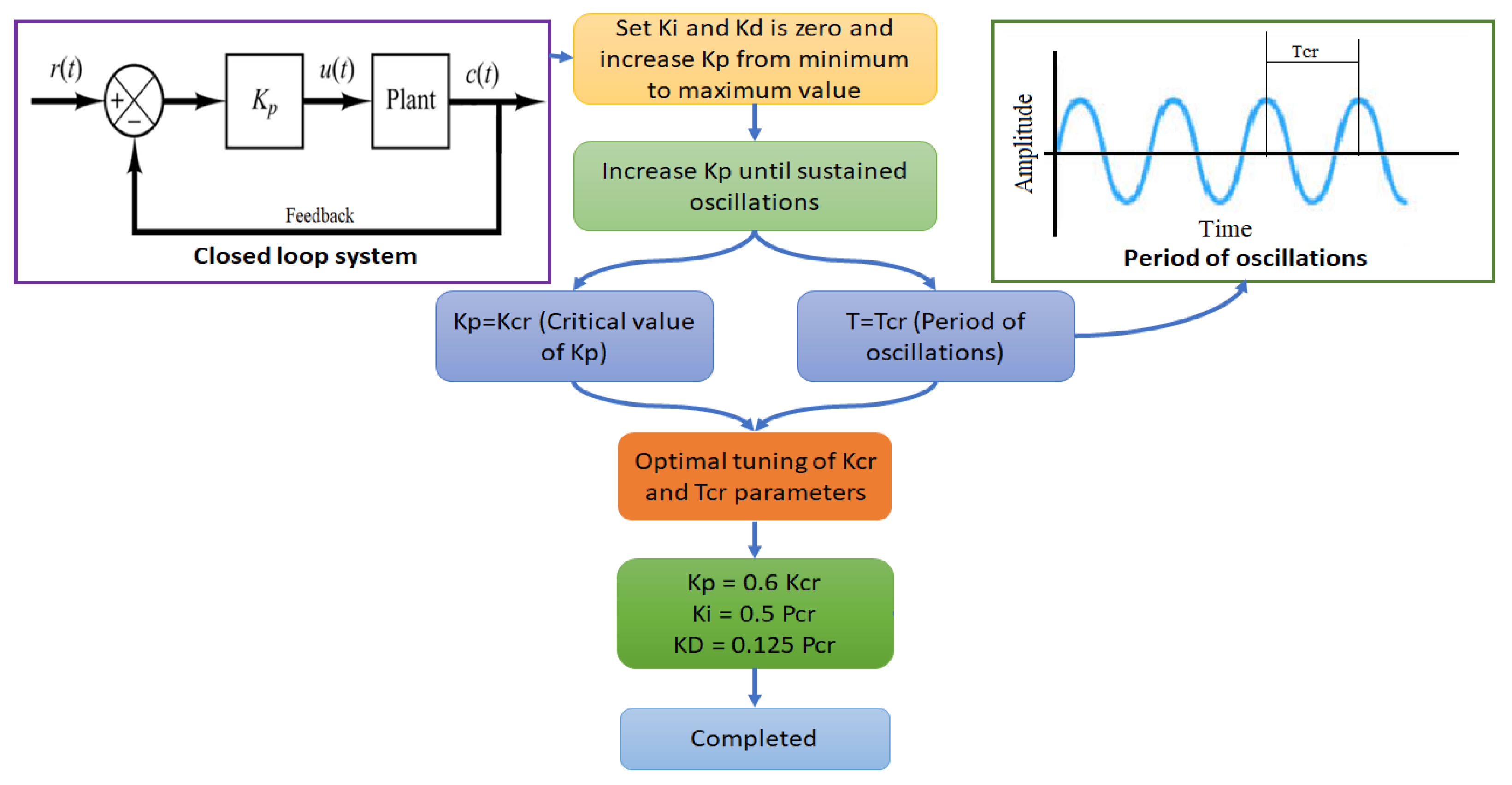
The most popular controller for managing EV SR motor speed and industrial processes is the PID controller. In order to achieve the intended output with little to no volatility in the values despite the various disturbances, it uses a closed-loop system to continuously examine the output and modify the input values. The PID controller eliminates the inaccurate reaction resulting from the difference in reference and feedback speeds. To estimate the final controller output, the erroneous response is multiplied by the controller’s proportional (Kp), integral (Ki), and derivative (Kd) sections, and then summed [34]. The duty cycle of the PWM pulses required for the SR motor to operate in a continuous loop is controlled by this output. Equation (17) represents the PID controller’s continuous output control signal (u(t)). Nonetheless, the EV SR motor’s efficiency is impacted by the chosen PID parameters. Under real-time operating conditions, it results in a drop in regenerative efficiency and an improvement in the EC. Therefore, calculating PID settings is crucial to an EV SR motor’s smooth operation. In the proposed work, using the Ziegler Nichols approach, the PID parameters are selected. When the SR motor dynamics are unknown or not readily available, the P, I, PI, and PID controllers are fine-tuned using the Ziegler Nichols approach [35]. Based on the different transient responses of the EV SR motor, the PID controller gains are estimated using the Ziegler Nichols rules. In a closed-loop system, the SR motor is coupled to the proportional controller. The Ki and Kd gains are first zeroed in this manner, and the Kp value is subsequently increased from zero to the maximum value until the system displays steady oscillations. Tcr (Tcr—critical period of oscillations) represents the period of oscillations, whereas Kcr (Kcr—critical value of Kp) represents the greatest value of Kp. The Ziegler Nichols tuning methodology is illustrated in Figure 3, and the PID tuning parameters are established by optimizing the Kcr and Tcr values.
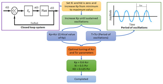
Figure 3.
Tuning methodology of PID controller gains using Ziegler Nichols approach.
Additionally, during steady-state experimentation, the mathematical model of the EV SR motor with a PID controller is built using MATLAB/Simulink. To assess the different output characteristics and create efficiency maps, the EV SR motor is run according to the best experimental design. EV SR motor and PID controller efficiency maps in various dynamic situations are developed as a result of the findings. Finally, the created PID controller efficiency maps have been integrated into an EV simulation model to examine various performance factors such as motor power, EC, battery SOC, and regeneration efficiency. The results of the simulation show that the complex nature of the EV system prevents the PID controller from achieving the desired levels of EC, SOC drop, and regenerative efficiency.
4.2. Intelligent Controller
For complicated linear and nonlinear EV systems, the intelligent controller is widely accepted as an acceptable controller. It produces effective and satisfactory results by managing a wide range of input and output factors. Ref. [36] discusses the intelligent controller’s design and development process in depth. Additionally, this work generates intelligent controller efficiency maps under real-time driving conditions by combining the proposed intelligent controller with an experiment involving a steady-state electric vehicle SR motor. The EV SR motor and controller efficiency maps are created for a range of real-time operating situations using the intelligent control approach. In order to estimate the EC and regenerative efficiency with a real-time driving cycle, the obtained efficiency maps are then fed into an EV simulation model. The intricacy of real-time electric vehicle operation is a challenge for the intelligent controller’s rule tuning. Therefore, the intelligent controller displays a less than ideal result with the EV simulation model. However, the results show that in comparison to the PID controller, the intelligent controller has a lower EC, a higher regeneration efficiency, and a lower battery SOC loss. Ultimately, in real-time driving conditions, the intelligent controller outperforms the PID controller in terms of EV performance.
4.3. Hybrid Controller
The creation of and improvement in intelligent controllers in real time usually involve a difficult procedure since numerous components, including MFs, control rules, input and output gains, and so forth, need to be changed. Furthermore, choosing the right PID controller parameters is crucial, and there are several approaches suggested for estimating the benefits of PID controllers. Even so, the PID controller’s performance can be enhanced by modifying the controller gains. Consequently, in order to adjust the PID gains in response to the EV SR motor’s static and dynamic speeds, a self-tuning hybrid controller is designed. It is the result of combining an intelligent controller with a PID one. An intelligent controller is used to change the PID controller’s gains in real time. Ref. [36] discusses the hybrid controller’s in-depth design and development procedures. Therefore, Equation (18) can be used to characterize the hybrid controller’s output control signal:
where Kp2, Ki2, and Kd2 represent the PID controller’s modified gains. Under real-time conditions, the self-learning controller is constructed based on the optimal tuning of PID gains through fuzzy rules. Next, an EV SR motor steady-state experiment is merged with the developed hybrid controller in an attempt to assess and generate efficiency maps in real time. In steady-state testing, under various dynamic conditions, a hybrid technique is used to develop the controller maps and motor maps for the EV SR motor. The created efficiency maps are then loaded into an EV simulation to analyze the vehicle’s performance across an actual driving cycle. The data indicate that in terms of battery SOC, EC, and energy recovery, the self-learning controller performs better than the PID and intelligent controllers. It might be challenging to adjust the rules and gains of a self-learning controller in real-time operating conditions. Thus, an adaptive supervisory self-learning controller is presented in this work to enhance vehicle performance under different dynamic conditions with minimal EC and maximum energy recovery. A thorough explanation of the supervisory self-learning controller is given in the next section.
4.4. Adaptive Supervisory Self-Learning Controller
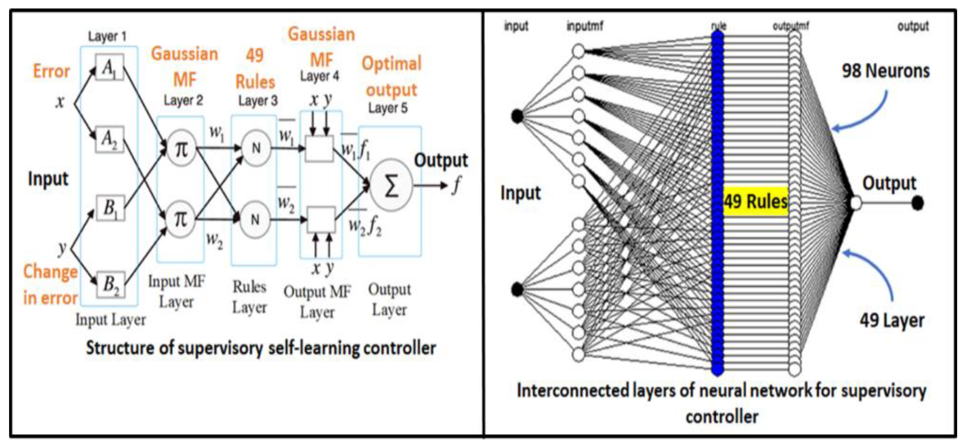
For EV analysis in a range of real-time circumstances, this research combines NNs and FLC into an adaptive supervisory self-learning controller. The combination of FLC and NNs yields a novel approach that combines the advantages of both methodologies, leading to a notable advancement in nonlinear modeling, learning, and mapping. Because of the latest advancements in SR motor technology, optimizing controller parameters for electric vehicles has become a difficult undertaking. Therefore, controller engineers need to implement some complex self-learning control algorithms in order to maximize the efficiency of SR motors in EVs. Because of its adaptability, the ASSC can be used in a wide variety of control applications.
Figure 4 shows the internal architecture of the ASSC method. The ASSC approach’s comprehensive design and development processes are covered in [36]. Also, the advantages and disadvantages of the above-mentioned controllers are presented in Table 2. Figure 5 shows a schematic illustration of the suggested energy management controllers in real time. The created ASSC is then incorporated into a steady-state experiment using an EV SR motor. The investigations are carried out in compliance with the design plan of the DoE. The efficiency maps for the EV SR motor and controller are then produced using the ASSC approach for various dynamic circumstances. Subsequently, the created efficiency maps are incorporated into an electric vehicle simulation model to examine the vehicle’s performance attributes throughout a real-time driving cycle. The ASSC-assisted EV simulation model yielded findings that show optimal performance in a variety of real-time driving scenarios for a number of performance metrics, including motor power, battery state of charge, energy recovery, battery current, and battery power. In real-time driving situations, the adaptive supervisory self-learning controller outperforms PID, FLC, and hybrid controllers in terms of performance. The experimental setup and the procedure of developing the efficiency map for the EV SR motor and controller are described in detail in the next section.

Figure 4.
Internal architecture of the proposed supervisory controller.
Table 2.
Advantages and disadvantages of different proposed control approaches.
Figure 5.
Schematic representation of a proposed energy management controller for the development of SR motor efficiency map.
5. Development of Controller and Motor Operating Map under Various Real-Time Operating Conditions
This section outlines the experimental setup of optimal SR motor and controller efficiency maps, which will be used to build the Simulink EV simulation model within the MATLAB software 2018b.
5.1. Experimental Setup for Map Development
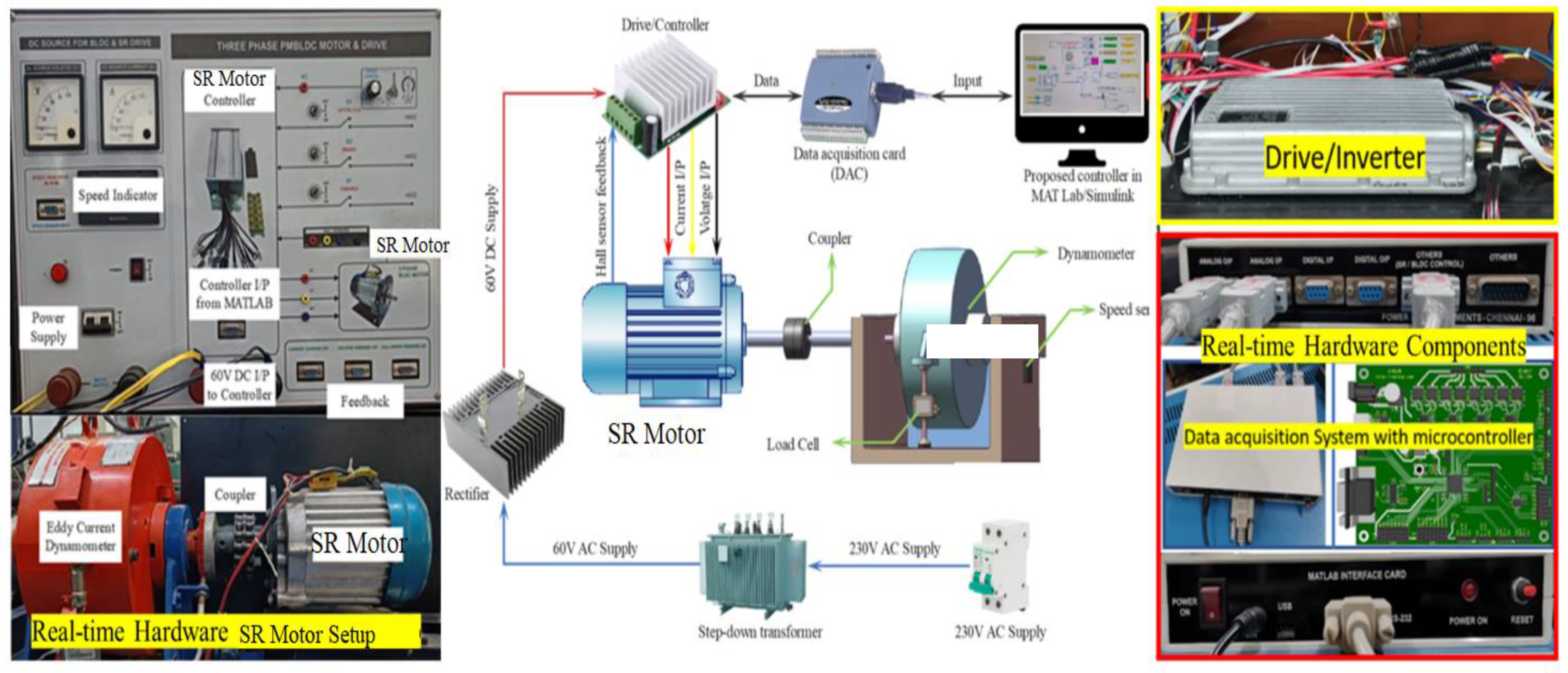
In this work, a 4.5 kW SR motor is used to create efficiency maps for real-time driving situations for a variety of energy management controllers (PID, FLC, hybrid, and ASSC). As shown in Figure 6, the SR motor is firmly mounted in the testbed, and the 12 kW eddy current dynamometer is securely attached to the SR motor’s shaft. As the SR motor operates at 60 V DC, the stepdown transformer in Figure 6 takes 230 V AC electricity and converts it to 60 V AC. Table 3 displays the SR motor’s technical specifications. The rectifier receives the lower voltage and uses it to convert 60 V AC to 60 V DC, which powers the SR motor. In this instance, the DC voltage of the SR motor is stabilized under varying load and speed conditions using a 400 V capacitor. The SR motor’s drive or inverter is directly connected to the 60 V DC output in order to test the efficacy of the different energy management controllers. The above-mentioned controllers (PID, FLC, hybrid, and ASSC) are connected to the STM32 microcontroller or DAC via an encrypted USB connection. They were designed in real-time using MATLAB/Simulink. The rectifier receives the lower voltage and uses it to convert 60 V AC to 60 V DC, which powers the SR motor. In this instance, the DC voltage of the SR motor is stabilized under varying load and speed conditions using a 400 V capacitor. The SR motor’s drive or inverter is directly connected to the 60 V DC output in order to test the efficacy of the different energy management controllers. The above-mentioned controllers (PID, FLC, hybrid, and ASSC) are connected to the STM32 microcontroller or DAC via an encrypted USB connection. They were designed in real-time using MATLAB/Simulink. After that, a serial port (RS 232) connects the STM32 microcontroller to the drive/inverter so it may transmit and receive data for a variety of operational scenarios. Furthermore, an SR motor can have its load manually adjusted at various speeds thanks to the dynamometer control interface. At that point, the developed energy management controllers, such as PID, FLC, hybrid, and ASSC, provide control signals to the SR motor drive/inverter in various real-world scenarios. The operating parameters of the SR motor and drive vary depending on the control signals received from different EMCs. Ultimately, the feedback data obtained from the real-time system are used to estimate the output responses (current and voltage) of the controller and motor. After that, based on the experimentally predicted output responses of the motor and controller in various dynamic scenarios, the efficiency maps of the controller/drive and motor are developed utilizing a variety of energy management controllers, including fuzzy, hybrid, supervisory, and PID techniques. The next section explores the specific process of developing a map.
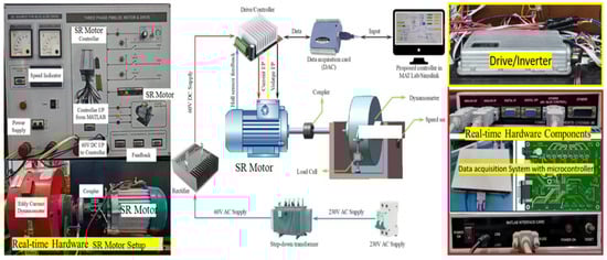
Figure 6.
Experimental setup for SR motor and controller efficiency map development with different strategies.
Table 3.
Technical specifications of SR motor used in EVs.
5.2. Optimal Energy Efficient Response Maps under Various Dynamic Operating Conditions
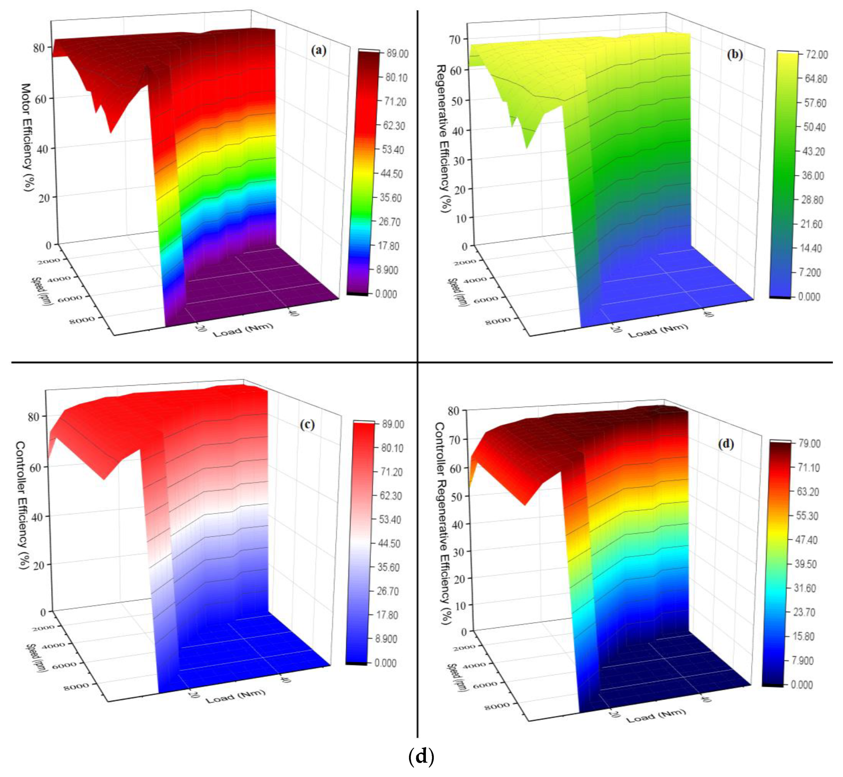
In this work, motor and controller efficiency maps with different EMCs are developed for the EV simulation model using the model-based calibration (MBC) technique. The step-by-step method of the MBC technique comprises the creation of maps, modeling, optimization, and DoE. This study uses a sophisticated method called the MBC methodology in MATLAB to examine how different variables affect future results. This study generates motor and controller efficiency maps for PID, intelligent, hybrid, and supervisory controllers under real-time operating conditions using a one-stage model technique. The operating and control settings of the motor and controller have a significant impact on their behavior. The motor’s operational parameters are torque and speed, and its control parameters are energy management controllers, which are control algorithms like PID, FLC, and so on. It is necessary to tune the control parameters (control algorithms) under a variety of dynamic conditions in order to obtain the best SR motor and controller response maps. To develop the model, the DoE technique is used to capture experimental motor response characteristics. Table 4 displays the operational parameter range and experimental control. Using the I-optimal technique, the design plan is developed in cooperation with the DoE (50 test situations). The Sobol-series DoE is used to collect the motor and controller data for different EMCs based on the test conditions, and the tests are conducted in compliance with the design plan. The collected data are transformed through processing, such that it approximates a normal distribution, improving the effectiveness of the model’s predicting capability. In this study, the empirical model behavior of the motor and controller are generated under dynamic conditions using a Gaussian elimination technique. With the empirical models of the motor and controller, the optimal efficiency maps for different EMCs of the SR motor and controller are developed under real-time operating conditions. The created SR motor and controller efficiency maps, which are used in vehicle modeling, are shown in Figure 7a–d using various energy management strategies, including PID, FLC, hybrid, and ASSC, under real-time conditions. Lastly, an EV simulation model is loaded with the produced controller and motor efficiency maps to analyze the vehicle’s performance characteristics.
Table 4.
Range of the operating parameters under different dynamic conditions.
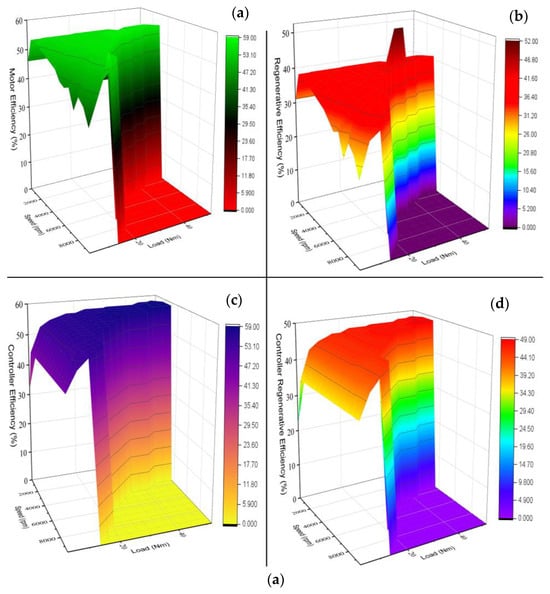
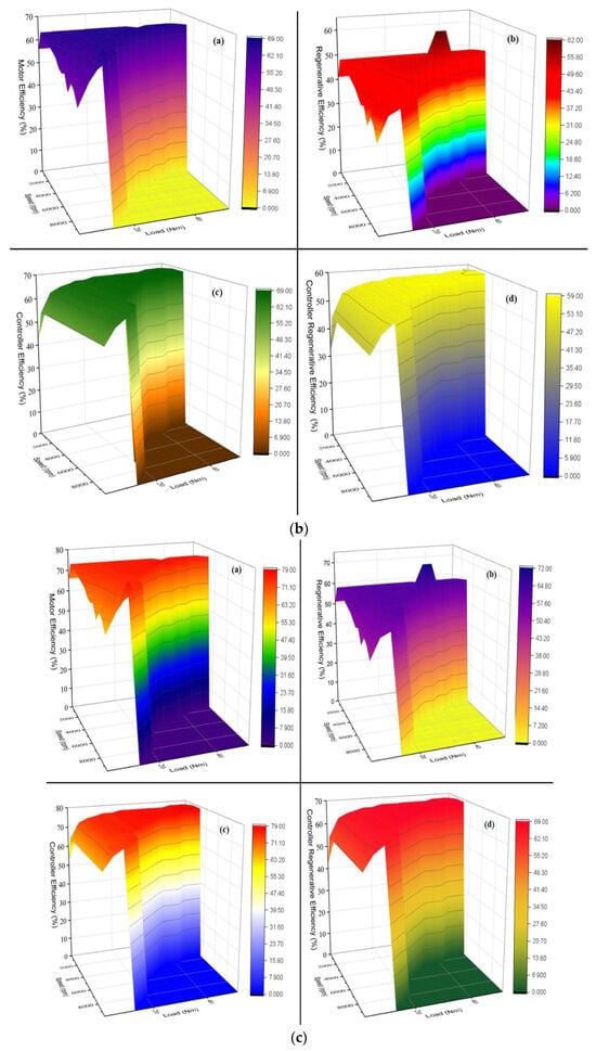

Figure 7.
(a) SR motor and controller efficiency maps for PID controller under real-time conditions. (b) SR motor and controller efficiency maps for intelligent controller under real-time conditions. (c) SR motor and controller efficiency maps for hybrid controller under real-time conditions. (d) SR motor and controller efficiency maps for adaptive supervisory self-learning controller under real-time conditions.
6. Simulation and Validation of the Developed SR Motor and Controller Maps with the Real-World Driving Cycle
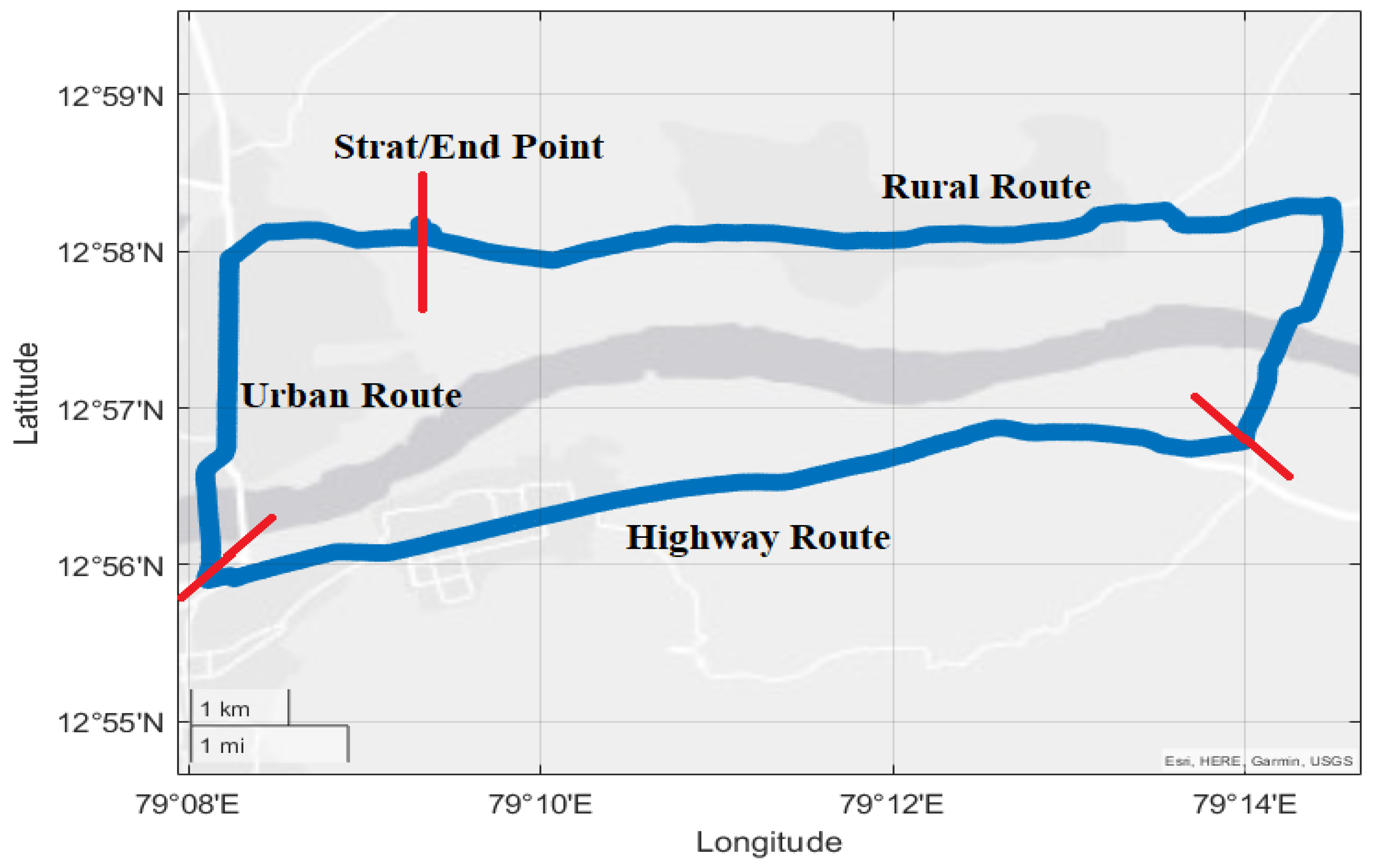
The driving cycle source is necessary to simulate the EC and battery discharge behavior. In this study, a real-time DC is created for all road situations, including urban, rural, and highway. Figure 8 shows the experimental process for a generating real-time DC in diverse driving situations, including urban, rural, and highway. This study examines the real-time DC design and development process, as well as route selection, trip timing, and experimental technique. The first and most crucial step in creating a driving cycle is deciding on a route [37]. The driving route in Vellore, India, is determined based on knowledge of local road and traffic conditions, as seen in Figure 9. Table 5 discusses the developed driving cycle characterizations for different driving routes. The selected driving route comprises all three types of road conditions: rural, highway, and urban. The whole length of the driving trip is around 33.45 km with different real-time road conditions.

Figure 8.
Methodology for development of real-time driving cycle under different road conditions.
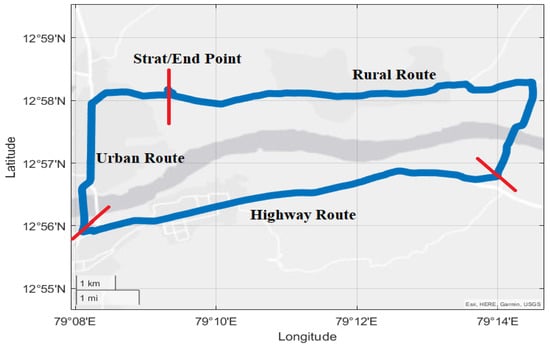
Figure 9.
Selected driving route for development of real-time driving cycle for urban, rural, and highway conditions.
Table 5.
Developed driving cycle characteristics.
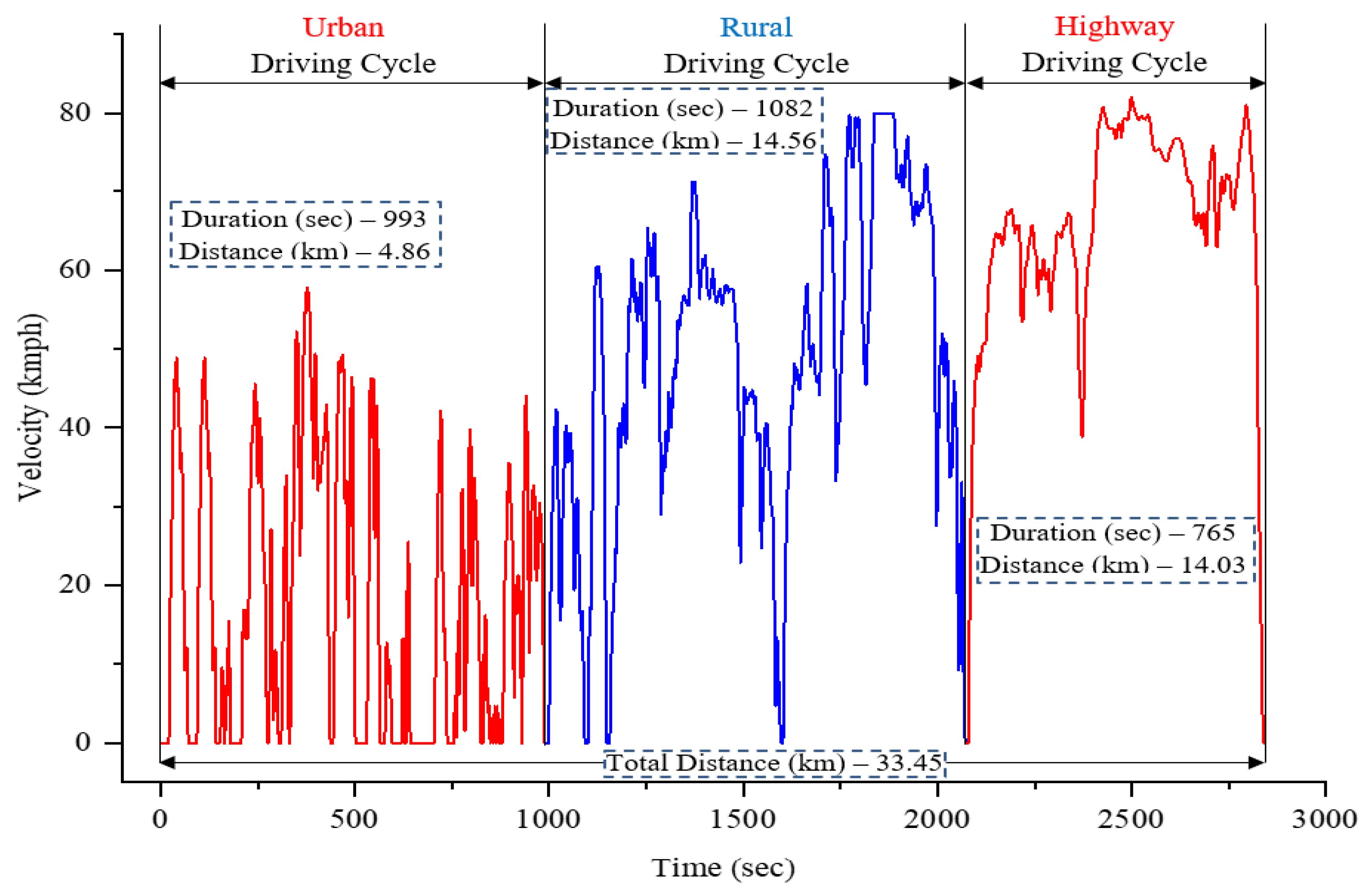
Furthermore, the electric two-wheeler is used to develop a real-time driving cycle for a variety of road situations. Table 1 shows the selected vehicle specifications. The chosen EV is connected to a microcontroller and mobile phone GPS. The microcontroller contains the vehicle’s speed as well as battery and motor performance statistics under different real-time driving conditions. In addition, the data collected from the mobile GPS include vehicle speed and location with X, Y, and Z directions along the different driving routes such as urban, rural and highway. During driving, the microcontroller stores the real-time data for different real-time driving conditions. Following that, a real-time DC is created using the collected data, with different driving routes including urban, rural, and highway. Figure 10 shows the profile of the created real-time driving cycle for different road conditions. A driving cycle is a set of data points that show the relationship between a vehicle’s speed and time. It is used to evaluate the performance of cars in several aspects including fuel efficiency, electric vehicle range, and harmful emissions. Furthermore, the established real-time driving cycle is used with the EV simulation model to estimate performance metrics such as power, C-rate, EC, battery discharge behavior, regeneration efficiency, and so on. Finally, this study integrates a real-time DC, a BLDC motor, and various energy management controller (such as PID, fuzzy, hybrid, and supervisory) efficiency maps with an EV simulation model to analyze the motor and battery’s performance in real-world driving situations.
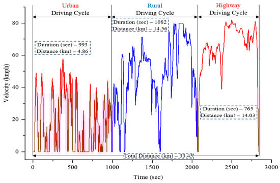
Figure 10.
Real-time driving cycle profile for different road conditions.
7. Results and Discussion
The objective of this study is to validate the effectiveness of an EV by integrating a real-time DC and various EMC efficiency maps into a simulation model. This section comprises an analysis and comparison of various EMCs with respect to the EV’s power output, battery current, C-rate, EC, and regeneration efficiency, all of which are evaluated under real-time operating conditions. It is also necessary to analyze the parameters associated with battery and motor performance to comprehend the fluctuations in and limitations of EVs under real-time operating conditions.
7.1. Motor Power
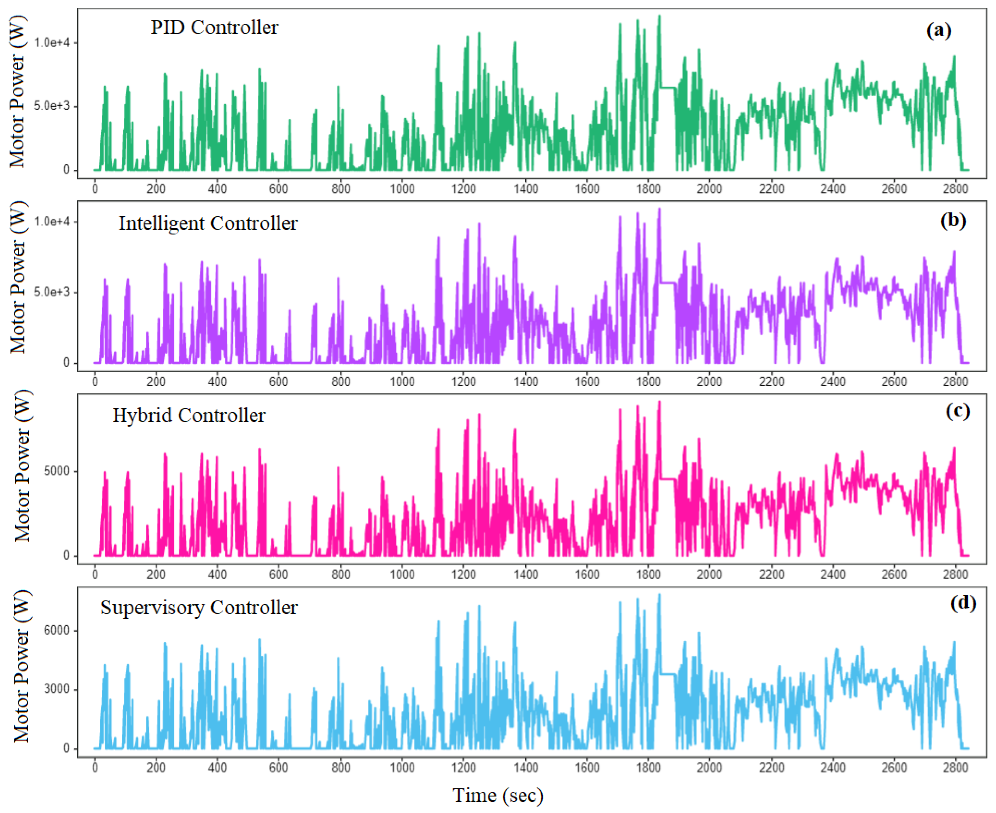
The intended speed and torque of EVs under different driving conditions have an impact on the motor power. Real-time analysis of motor power fluctuations is performed in this study using various energy management controllers. The various EMCs such as intelligent, ASSC, PID, and hybrid controllers were used under different road conditions, and the resulting motor fluctuations are illustrated in Figure 11. According to the findings, the average motor power of the PID, intelligent, hybrid, and supervisory controllers is 5.8, 4.3, 3.1, and 2.3 kW in various driving situations. The results show that the lack of real-time parameter modification in conventional controllers (PID, intelligent, and hybrid) causes the maximal motor power fluctuations compared to the proposed controller under a variety of road conditions. Thus, the proposed supervisory controller will reduce EC and increase the driving range of EVs under various driving conditions. Furthermore, the maximum motor power of the PID, intelligent, hybrid, and supervisory controllers is 12.2, 11.1, 9.2, and 7.8 kW, respectively. The suggested supervisory controller shows less fluctuations in maximal motor power than the standard controllers, such as PID, intelligent, and hybrid controllers. By introducing large variations in motor power, a traditional controller reduces driving range and increases battery discharge rate and energy consumption under different driving conditions. To overcome this problem, the proposed controller uses its self-learning capabilities to effectively mitigate the real-time power variation of the motor. In the end, in real-time driving situations, the suggested supervisory controller yields excellent performance results in terms of discharge rate, EC, and regeneration efficiency.
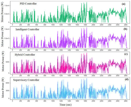
Figure 11.
Variations in motor power with different energy management controllers under varied driving conditions.
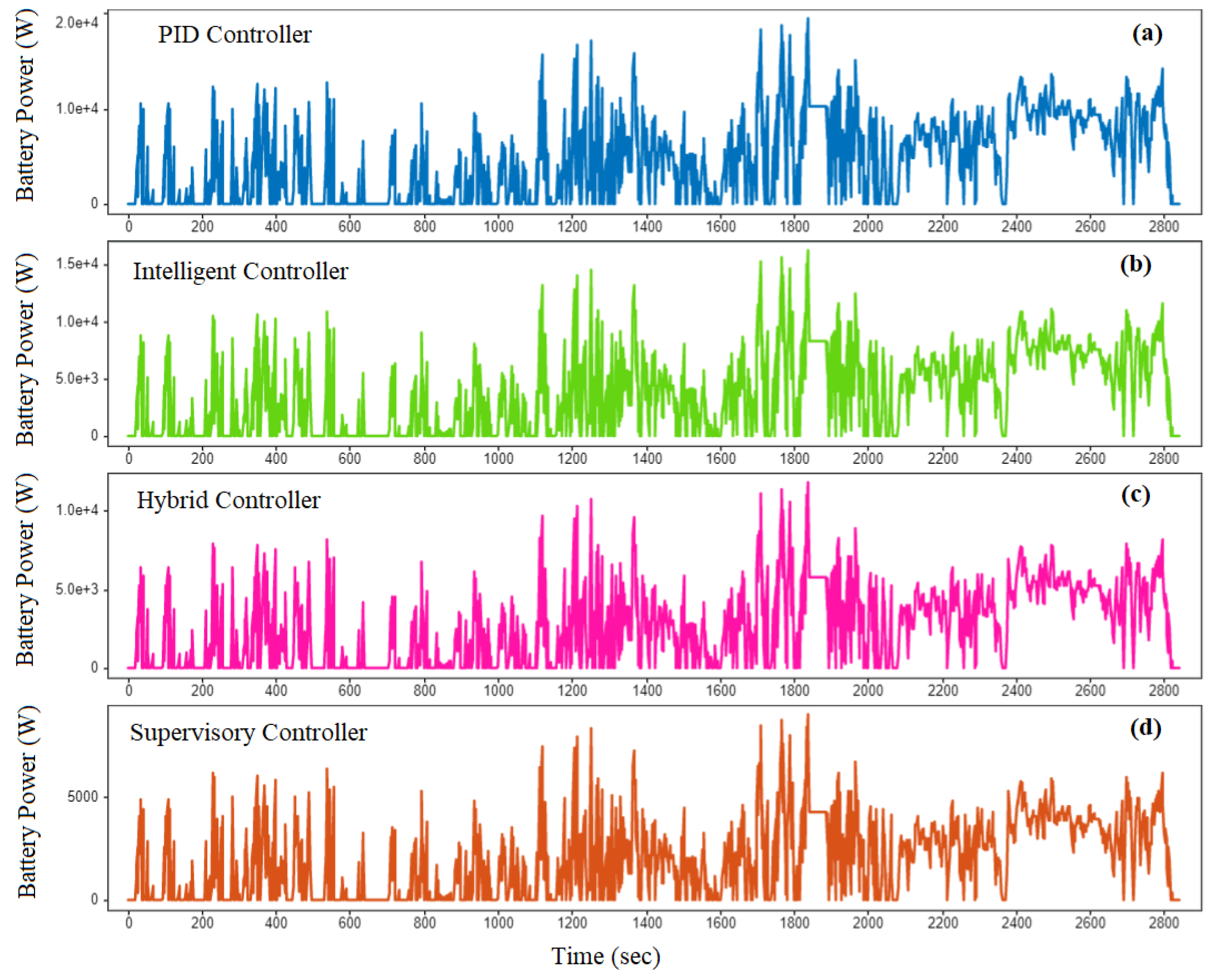
7.2. Battery Power
The maximal velocity of an EV during performance is affected by the electricity produced by its battery at a specific instant. Battery power varies according to the temperature and discharge rate under various dynamic conditions. The various EMCs such as intelligent, ASSC, PID, and hybrid were used under different road conditions such as urban, rural, and highway, and the resulting battery power fluctuations are illustrated in Figure 12. The resultant graphs show that the proposed controller, in comparison to other traditional controllers (PID, intelligent, and hybrid), shows fewer variations under battery power in urban, rural, and highway driving conditions. In different road circumstances, the average battery power of the different EMCs is 9.3, 6.4, 4.6, and 2.7 kW, respectively. The conventional controllers have high battery power variations, hence the battery discharge characteristics will be affected under real-time driving conditions. This will lead to decreases in the operational range of EVs due to the increased energy consumption. Then, in a variety of driving circumstances, the supervisory controller exhibits the minimal battery power variation and thus will aid in reducing EC and increasing driving range. Also, the maximum battery power of the PID, intelligent, hybrid, and supervisory controllers is 19.6, 16.3, 10.7, and 9.1 kW, respectively. The conventional controllers (PID, intelligent, and hybrid) generate the greatest battery power fluctuations in response to varying road conditions, resulting in an increase in EC and battery depletion rate. However, the supervisory controller shows minimal battery power variations compared to the other traditional controllers under different real-time driving conditions. As a result, the proposed controller will help lower battery power deviation, improving EVs’ EC and driving range in a range of real-world driving scenarios.
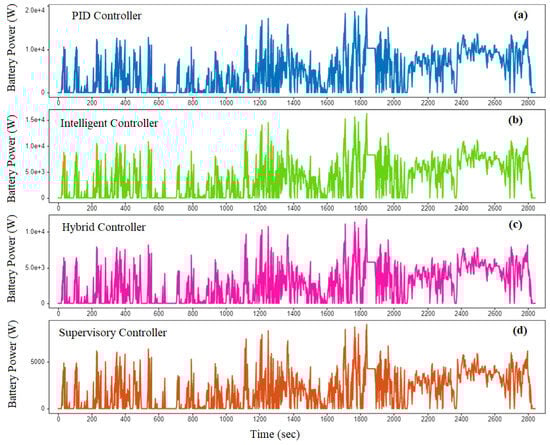
Figure 12.
Variations in battery power with different energy management controllers under varied driving conditions.
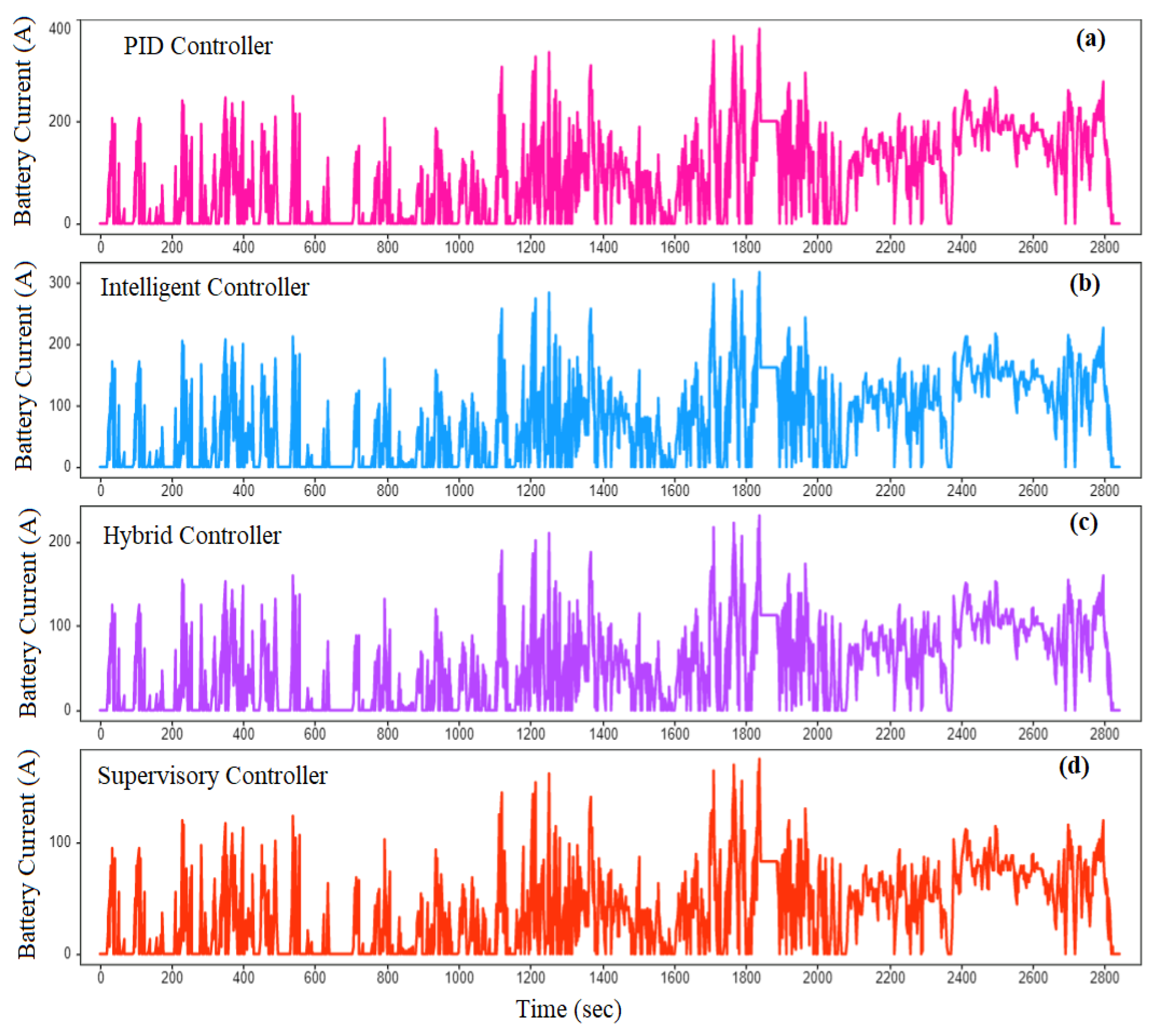
7.3. Battery Current
In electric vehicles, the accelerator and brake pedal positions affect the magnitude and direction of battery current. Figure 13 depicts the variations in battery current caused by a variety of energy management controllers and road conditions. The graph shows that the average battery current of PID, intelligent, hybrid, and supervisory controllers is 196, 162, 113, and 74 A, respectively. Due to the high nonlinear behavior of the vehicle, the traditional controllers (PID, intelligent, and hybrid) show higher battery current than the recommended controller under real-time driving conditions. Also, due to the absence of real-time parameter tunings across various travelling conditions, conventional controllers are incapable of achieving the highest possible vehicle performance. As a result, the proposed supervisory controller effectively reduces battery current fluctuations under real-time operating conditions by utilizing its adaptive self-learning capabilities. Moreover, the maximum battery current of various EMCs is 383.1, 319.6, 232.5, and 176.8 A, respectively. The absence of real-time parameter correction in conventional controllers will result in a decline in the electric vehicle’s performance, rapid depletion of the battery SOC, and an increase in EC under different conditions. That being said, the proposed supervisory controller shows very little fluctuation in battery current under rural, urban, and highway road conditions. Therefore, it is used to lower EC and extend operating range, as well as to improve battery discharge rate in different driving situations. In comparison to other traditional controllers, the proposed controller improves battery power, current, and SOC, EC, driving range, and regenerative efficiency in real-time driving scenarios.
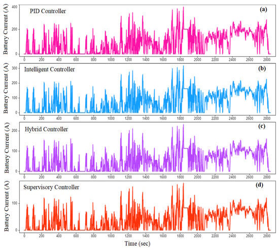
Figure 13.
Variations in battery current with different energy management controllers under varied driving conditions.
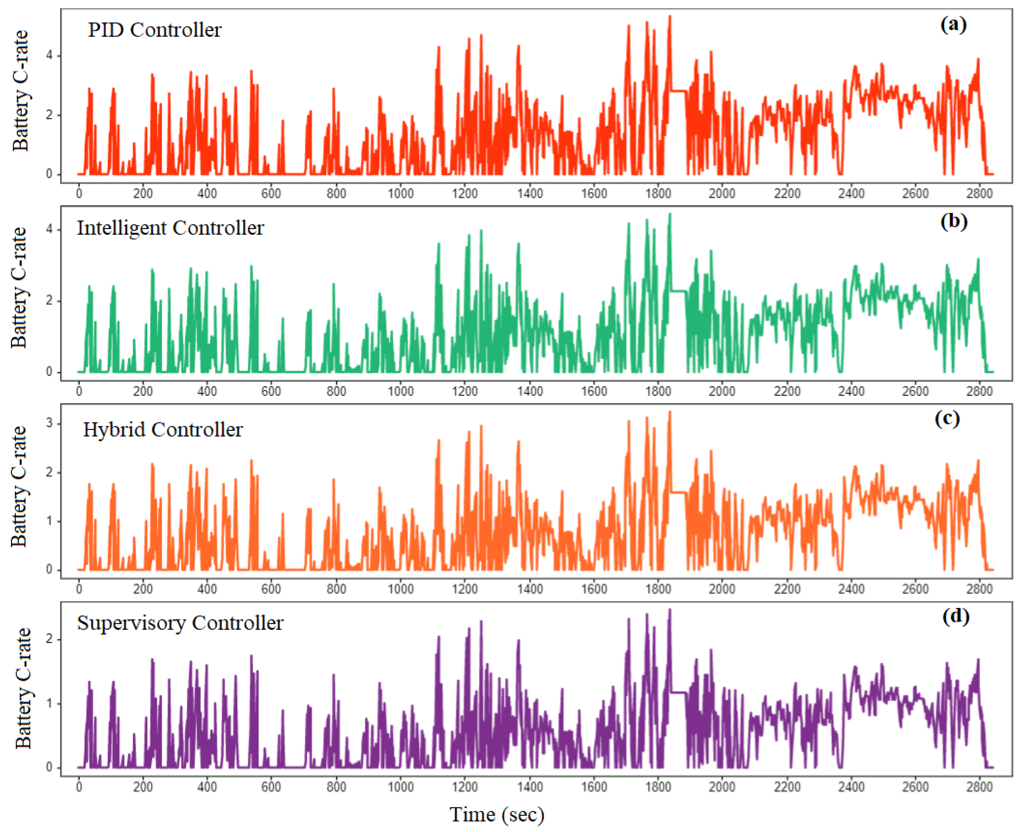
7.4. Battery C-Rate
The battery discharge rate has an impact on the C-rate in a variety of real-world driving conditions. The energy management controllers such as intelligent, ASSC, PID, and hybrid were used under different conditions such as urban, rural, and highway, and the resulting variations in C-rate are illustrated in Figure 14. From the figure, the maximum and average C-rates of various EMCs are 5.36, 4.8, 3.25, and 2.48, and 2.7, 1.6, 0.8, and 0.4, respectively. In comparison to the proposed supervisory controller, the traditional controllers exhibit greater C-rate variations under different real-time road conditions. So, with the traditional controllers, the battery discharge characteristics will degrade under real-time driving conditions. In urban, rural, and highway conditions, a higher C-rate also shortens battery life and decreases battery discharge efficiency. Furthermore, an increase in C-rate will result in elevated battery temperatures and greater energy dissipation during mobility at varying velocities. Therefore, it is not feasible to attain the optimal performance of EVs under various real-time driving conditions using conventional controllers. However, the implementation of the proposed supervisory controller will contribute to enhanced performance through the reduction in C-rate variations across various real-time driving conditions. The proposed controller has the ability to adjust the different control parameters instantly because of its adaptive self-learning capabilities. Consequently, it can effortlessly manage nonlinear behavior systems of EVs in a variety of dynamic scenarios. Therefore, in this situation, under real-time operating conditions, the supervisory controller will improve battery life and discharge rate. Additionally, it will reduce the energy consumption of EVs and increase their operating range in highway, rural, and urban situations. Ultimately, it is clear that in various driving circumstances, the supervisory controller performs better than other EMCs in terms of C-rate, power, EC, performance, range, recovery energy, etc.
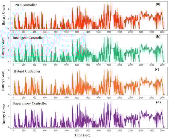
Figure 14.
Variations in C-rate with different energy management controllers under varied driving conditions.
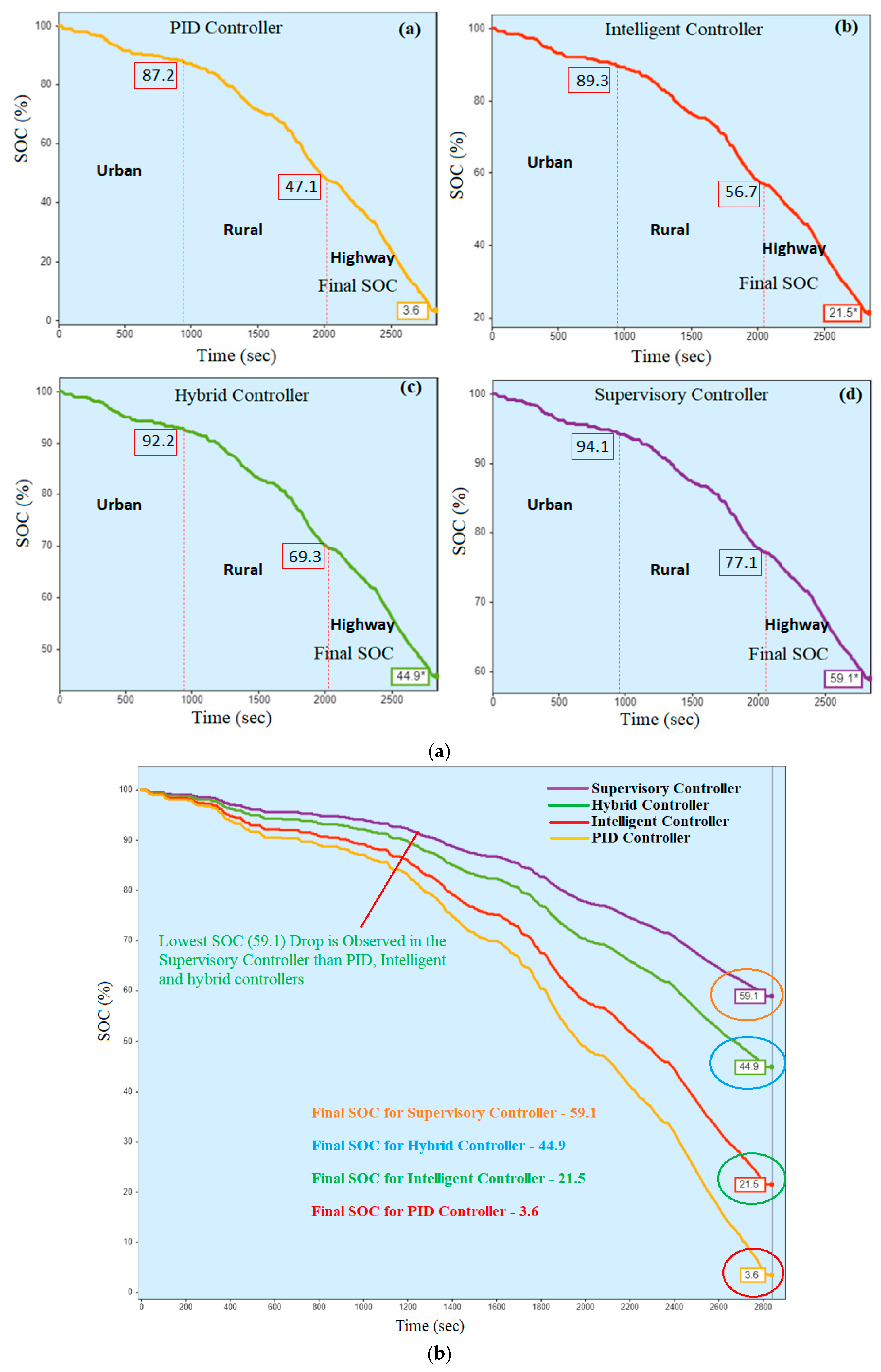
7.5. State of Charge
One important metric for assessing an EV’s remaining driving range is battery SOC, which serves as a direct measure of the entire amount of energy in the battery during a trip. Figure 15a illustrates the variations in battery state of charge (SOC) corresponding to distinct EMCs across a range of real-time driving conditions. The PID controller end-of-trip (EOT) SOC is 87.2, 47.1, and 3.6% under different road (urban, rural, and highway) conditions. The EOT values for intelligent and hybrid controllers are 89.3, 56.7, and 21.5, and 92.2, 69.3, and 44.9%, respectively. The proposed controller’s EOT SOC in urban, rural, and highway driving scenarios is 94.1, 77.1, and 59.1%, respectively. The findings show that the EOT SOC for different energy management controllers under urban driving conditions is 87.2, 89.3, 92.2, and 94.1%. When compared to the other traditional controllers, the supervisory controller exhibits the lowest SOC drop (95.3%) in urban driving conditions. Owing to the very nonlinear real-time behavior of EVs, conventional controllers are unable to maintain the correct SOC level in a variety of road conditions. Thus, due to the self-learning capabilities, the suggested controller is suitable for reducing the variations in battery SOC corresponding to distinct EMCs and for extending driving range under real-time driving conditions. Additionally, the EOT SOC values are 47.1, 56.7, 69.3, and 77.1% for rural driving situations with different energy management controllers. The supervisory controller records a lower SOC drop than the other conventional controllers in rural driving circumstances because of its real-time parameter-tuning capabilities. The battery discharge rate will increase due to the higher SOC drop of the PID, intelligent, and hybrid controllers, which will also increase the EC and reduce the vehicle’s operating range. Furthermore, Figure 15b displays the highway EOT SOC of the different energy management controllers. The final SOC levels of the supervisory, intelligent, hybrid, and PID controllers are shown in the figure as 3.6, 21.5, 44.9, and 59.1%, respectively. The supervisory self-learning controller outperforms the traditional controllers (PID, intelligent, and hybrid) in terms of trip SOC reductions at the EOT under different real-time conditions. Thus, the proposed supervisory controller is used to improve the driving experience and range under different real-time driving conditions.
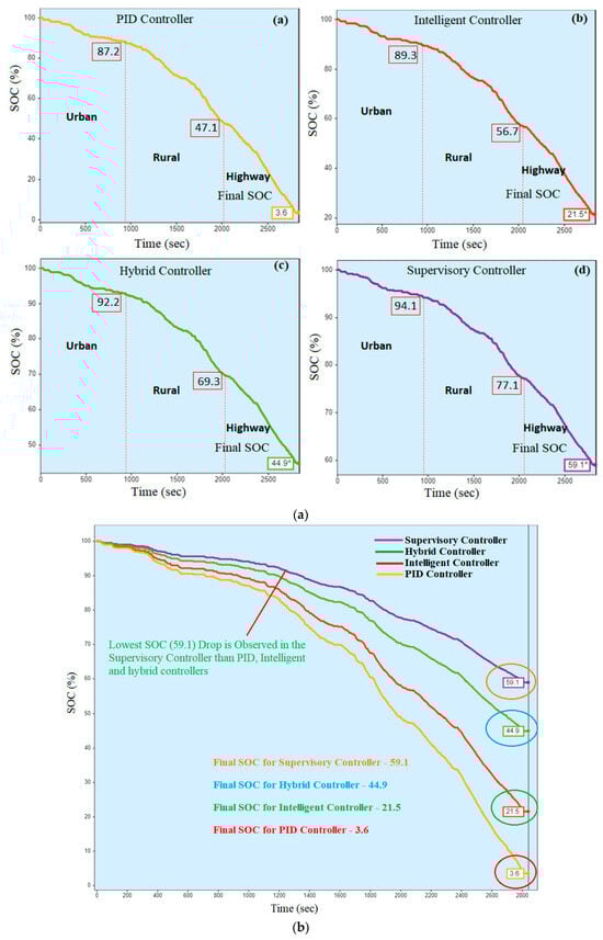
Figure 15.
(a) Individual SOC variations of various energy management controllers under urban, rural, and highway driving conditions. (b) Final SOC variations with different energy management controllers.
7.6. Energy Consumption and Regenerative Efficiency
The amount of energy used and recovered during acceleration and braking, which is mostly dependent on the driving conditions and features of road segments, vehicle physical parameters, speed, and acceleration, is directly connected with the entire driving range of electric vehicles. The regeneration efficiency and total energy consumption per kilometer for different EMCs are shown in real time in Figure 16. In various driving situations, the overall energy consumption of PID, intelligent, hybrid, and supervisory controllers is 97.21, 85.63, 60.14, and 44.67 Wh/km, respectively. Because of its self-tuning capabilities, the supervisory controller can tune and optimize the control settings in real-time situations, resulting in a low EC (44.67 Wh/km) compared to the other conventional controllers. The EC of an EV decreases as a result of the nonlinear behavior of EVs under different conditions, which makes it difficult for traditional controllers to modify and optimize control settings in real time. As a result, under various dynamic road conditions, the driving range of an electric vehicle will increase with the minimal EC (44.67 Wh/km) of the suggested controller. Furthermore, Figure 16 illustrates that the corresponding regenerative efficiencies of the PID, intelligent, hybrid, and supervisory controllers are −21.81, −27.73, −41.64, and −58.28 Wh, respectively. According to the data, compared to the other conventional controllers, the supervisory controller (−58–28 Wh) recovers the highest amount of regenerative energy. In addition, the hybrid controller recovers a substantially higher amount of energy than both the intelligent and PID controllers. However, under different real-time driving conditions, the proposed controller recovers more regenerative energy than the standard controllers. The maximal energy recovery rate will definitely increase the EV’s operating range under different conditions. Lastly, an efficient energy management controller enhances the vehicle’s power, efficiency, SOC, energy consumption, regenerative efficiency, etc., according to an analysis of a variety of performance characteristics pertaining to various EMCs (PID, intelligent, hybrid, and ASSC) under varied real-time driving conditions.
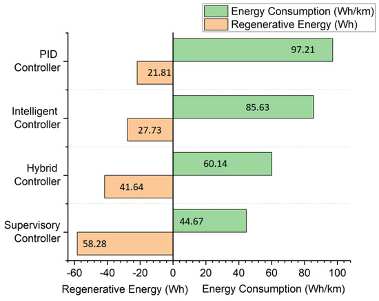
Figure 16.
Different energy management controllers’ energy consumption and regenerative efficiency.
8. Conclusions
This study has been conducted to optimize the energy consumption of EVs by developing a robust energy management controller and testing it under various real-time driving conditions. This study employs various methodologies to develop the efficiency maps, the EV model, and a real-time DC which are then combined with the developed EMCs, such as PID, intelligent, hybrid, and supervisory, to enhance the EV performance under real-time driving conditions. A MATLAB/Simulink-based mathematical model is formulated for an EV with an SR motor. Through a novel experimental approach, the efficiency maps of the motor and various EMCs are developed. These maps are then integrated into a model-in-loop (MIL) EV test platform to assess the performance of different EMCs in EVs under real-time driving conditions. Further, for the validation process, a real-time DC is implemented for different types of road conditions, which include urban, rural, and highway roads. This DC is linked to the MIL-based EV test platform real-time analysis of energy consumption and battery discharge patterns. The present study concludes by simulating the EV model using various EMC efficiency maps and the real-time DC to analyze parameters like motor power, battery power, C-rate, energy consumption (EC), state of charge (SOC), regenerative efficiency, and more. The validation and interpretation outcomes of this research paper are summarized below.
- To carry out the EV simulation, the necessary efficiency maps of the SR motor and the controllers are developed under real-time conditions. For the validation of the model, a real-time driving cycle is designed to encompass diverse road conditions, including urban, rural, and highway scenarios.
- The supervisory controller performs better than conventional controllers as it exhibits less variations, based on the SR motor and battery performance characteristics in controllers in urban, rural, and highway driving conditions, as presented in Table 6.
Table 6. Output parameters of EV with different energy management controllers under real-time conditions with SR motor.
- The proposed supervisory self-learning controller achieves significantly less energy consumption (44.67 Wh/km) compared to PID (97.21 Wh/km), intelligent (85.63 Wh/km), and hybrid (60.14 Wh/km) controllers under varying real-time operating conditions. This suggests an improvement in battery utilization behavior and operating range for the EV under dynamic conditions.
- The end-of-trip state-of-charge (SOC) drop for the proposed supervisory controller (59.1%) is notably lower than that of the PID (3.6%), intelligent (21.5%), and hybrid (44.9%) controllers across different road conditions. Consequently, the supervisory controller enhances battery efficiency and overall EV performance in real-time conditions.
- The regenerative efficiency of the PID, intelligent, hybrid, and supervisory controllers is recorded as −21.81, −27.73, −41.64, and −58.28 Wh under varying road conditions. Notably, the proposed supervisory controller exhibits greater energy recovery compared to the other conventional controllers. This improvement contributes to enhanced battery consumption behavior and extended driving range under real-time conditions.
The current study improves the performance of electric vehicles (EVs) under real-time driving conditions through the implementation of the proposed adaptive supervisory self-learning controller. It not only reduces energy consumption (EC) but also enhances the driving range across various road conditions. Although the potential limitation of the suggested controller is its heavy reliance on training information, impacting its overall performance, it can be overcome by leveraging advanced controllers like the multi-adaptive neuro fuzzy inference system (MANFIS). Furthermore, specialized optimization techniques could be employed to train the data. Investigating these alternatives could contribute to achieving a more stable and effective performance for the proposed controller.
Author Contributions
Methodology, B.A. and D.U.; investigation, D.U.; resources, B.A.; data curation, B.A.; writing—original draft preparation, P.S.; writing—review and editing, P.S.; supervision, B.A.; project administration, B.A. All authors have read and agreed to the published version of the manuscript.
Funding
This study is supported and carried out as part of the funding from the European Union under the Erasmus scheme of Jean Monnet Modules (Grant No: JMO-2023-HEITCH-RSCH—101127804), and as part of the funding from the “British Council” for Going Global Partnerships Industry Academia Grant 2023-24 (Application Unique ID-28).
Data Availability Statement
Data are contained within the article.
Acknowledgments
The authors of this research work wish to acknowledge the Management of the Vellore Institute of Technology, Vellore, for the resources and amenities provided whilst conducting the research.
Conflicts of Interest
The authors declare no conflict of interest.
Abbreviations
| ASSC | Adaptive Supervisory Self-Learning Controller |
| BLDC Motor | Brushless Direct Current Motor |
| BMP | Battery Motoring Power |
| BRP | Battery Regenerative Power |
| DC | Driving Cycle |
| DOE | Design of Experiments |
| DOF | Degree of Freedom |
| EC | Energy Consumption |
| EMC | Energy Management Controller |
| EMs | Electric Motors |
| EMS | Energy Management System |
| EOT | End of Trip |
| EV | Electric Vehicle |
| FLC | Fuzzy Logic Controller |
| GHG | Green House Gas |
| GPS | Global Positioning System |
| GVM | Grass Vehicle Mass |
| GVW | Grass Vehicle Weight |
| HEV | Hybrid Electric Vehicle |
| HIL | Hardware In Loop |
| IM | Induction Motor |
| MANFIS | Multi-Adaptive Neuro Fuzzy Inference System |
| MBC | Model-Based Calibration |
| MEP | Motor Electric Power |
| MIL | Model In Loop |
| MMP | Motor Mechanical Power |
| MRP | Motor Regenerative Power |
| Ms | Motor Speed |
| Mt | Motor Torque |
| NN | Neural Network |
| OBD | On-Board Diagnosis |
| PID | Proportional–Integral–Derivative |
| SOC | State of Charge |
| SR Motor | Switched Reluctance Motor |
| Ws | Wheel Speed |
| Wt | Wheel Torque |
References
- Singirikonda, S.; Pedda, O.Y. Investigation on performance evaluation of electric vehicle batteries under different drive cycles. J. Energy Storage 2023, 63, 106966. [Google Scholar] [CrossRef]
- Itani, K.; De Bernardinis, A.; Khatir, Z.; Jammal, A. Comparison between two braking control methods integrating energy recovery for a two-wheel front driven electric vehicle. Energy Convers. Manag. 2016, 122, 330–343. [Google Scholar] [CrossRef]
- Li, Z.; Khajepour, A.; Song, J. A comprehensive review of the key technologies for pure electric vehicles. Energy 2019, 182, 824–839. [Google Scholar] [CrossRef]
- Vignesh, R.; Ashok, B. Intelligent energy management through neuro-fuzzy based adaptive ECMS approach for an optimal battery utilization in plugin parallel hybrid electric vehicle. Energy Convers. Manag. 2023, 280, 116792. [Google Scholar] [CrossRef]
- Ibrahim, M.A.; Alsammak, A.N. Dynamic Modelling and Current Control for Switched Reluctance Motor Drives in Electric Vehicles. IOP Conf. Ser. Mater. Sci. Eng. 2023, 1295, 012006. [Google Scholar] [CrossRef]
- Miranda, M.H.; Silva, F.L.; Lourenço, M.A.; Eckert, J.J.; Silva, L.C. Electric vehicle powertrain and fuzzy controller optimization using a planar dynamics simulation based on a real-world driving cycle. Energy 2022, 238, 121979. [Google Scholar] [CrossRef]
- Abou-ElSoud, A.M.; Nada, A.S.; Abdel-Aziz, A.A.; Sabry, W. Torque ripples reduction of electric vehicle synchronous reluctance motor drive using the strong action controller. Ain Shams Eng. J. 2024, 15, 102428. [Google Scholar] [CrossRef]
- Li, Y.; Deng, H.; Xu, X.; Wang, W. Modelling and testing of in-wheel motor drive intelligent electric vehicles based on co-simulation with Carsim/Simulink. IET Intell. Transp. Syst. 2019, 13, 115–123. [Google Scholar] [CrossRef]
- Saiteja, P.; Ashok, B.; Wagh, A.S.; Farrag, M.E. Critical review on optimal regenerative braking control system architecture, calibration parameters and development challenges for EVs. Int. J. Energy Res. 2022, 46, 20146–20179. [Google Scholar] [CrossRef]
- Hu, Z.; Su, R.; Wang, Y.; Wang, B.; Huang, L.; Lu, Y. Security Enhancement for Longitudinal Vehicle Platooning Under Denial-of-Service Attacks: From Resilient Controller Design Perspective. IFAC-Pap. Online 2023, 56, 1088–1093. [Google Scholar] [CrossRef]
- Bageshwar, V.L.; Garrard, W.L.; Rajamani, R. Model predictive control of transitional maneuvers for adaptive cruise control vehicles. IEEE Trans. Veh. Technol. 2004, 53, 1573–1585. [Google Scholar] [CrossRef]
- Hu, Z.; Liu, S.; Luo, W.; Wu, L. Intrusion-detector-dependent distributed economic model predictive control for load frequency regulation with PEVs under cyber-attacks. IEEE Trans. Circuits Syst. I Regul. Pap. 2021, 68, 3857–3868. [Google Scholar] [CrossRef]
- Hu, Z.; Su, R.; Zhang, K.; Xu, Z.; Ma, R. Resilient Event-Triggered Model Predictive Control for Adaptive Cruise Control Under Sensor Attacks. IEEE/CAA J. Autom. Sin. 2023, 10, 807–809. [Google Scholar] [CrossRef]
- Diao, K.; Sun, X.; Lei, G.; Bramerdorfer, G.; Guo, Y.; Zhu, J. System-level robust design optimization of a switched reluctance motor drive system considering multiple driving cycles. IEEE Trans. Energy Convers. 2020, 36, 348–357. [Google Scholar] [CrossRef]
- Zhu, Y.; Wu, H.; Zhen, C. Regenerative braking control under sliding braking condition of electric vehicles with switched reluctance motor drive system. Energy 2021, 230, 120901. [Google Scholar] [CrossRef]
- Vignesh, R.; Ashok, B.; Kumar, M.S.; Szpica, D.; Harikrishnan, A.; Josh, H. Adaptive neuro fuzzy inference system-based energy management controller for optimal battery charge sustaining in biofuel powered non-plugin hybrid electric vehicle. Sustain. Energy Technol. Assess. 2023, 59, 103379. [Google Scholar] [CrossRef]
- Sivasamy, S.; Sundaramoorthy, P.; Beno, M. A comprehensive Investigation of Outer Rotor Permanent Magnet Switched Reluctance Motor for Enhanced Performance in Electric Vehicles. IEEE Can. J. Electr. Comput. Eng. 2023, 46, 342–347. [Google Scholar] [CrossRef]
- Fang, G.; Bauman, J. Optimized switching angle-based torque control of switched reluctance machines for electric vehicles. In Proceedings of the 2020 IEEE Transportation Electrification Conference & Expo (ITEC), Chicago, IL, USA, 23–26 June 2020; pp. 186–191. [Google Scholar]
- Bishop, J.D.; Doucette, R.T.; Robinson, D.; Mills, B.; McCulloch, M.D. Investigating the technical, economic and environmental performance of electric vehicles in the real-world: A case study using electric scooters. J. Power Sources 2011, 196, 10094–10104. [Google Scholar] [CrossRef]
- Dhakal, R.; Parameswaran, S.; Muthukumar, R.; Moussa, H. Performance Analysis of Electrical Vehicle Battery Thermal Management System; SAE Technical Paper; SAE International: Warrendale, PA, USA, 2022. [Google Scholar]
- Saiteja, P.; Ashok, B. Critical review on structural architecture, energy control strategies and development process towards optimal energy management in hybrid vehicles. Renew. Sustain. Energy Rev. 2022, 157, 112038. [Google Scholar] [CrossRef]
- Li, W.; Xu, H.; Liu, X.; Wang, Y.; Zhu, Y.; Lin, X.; Wang, Z.; Zhang, Y. Regenerative braking control strategy for pure electric vehicles based on fuzzy neural network. Ain Shams Eng. J. 2024, 15, 102430. [Google Scholar] [CrossRef]
- Hamouda, M.; Abdel Menaem, A.; Rezk, H.; Ibrahim, M.N.; Számel, L. Numerical estimation of switched reluctance motor excitation parameters based on a simplified structure average torque control strategy for electric vehicles. Mathematics 2020, 8, 1213. [Google Scholar] [CrossRef]
- Ahmed, M.; Naiju, C.D. Modeling and Simulation for Hybrid Electric Vehicle with Parallel Hybrid Braking System for HEV; SAE Technical Paper; SAE International: Warrendale, PA, USA, 2018. [Google Scholar]
- Vinh, V.Q.; Ha, V.T. Improved Torque Ripple of Switched Reluctance Motors using Sliding Mode Control for Electric Vehicles. Eng. Technol. Appl. Sci. Res. 2023, 13, 10140–10144. [Google Scholar] [CrossRef]
- Hasanhendoei, G.R.; Afjei, E.; Naseri, M.; Azad, S. Automatic and real time phase advancing in BLDC motor by employing an electronic governor for a desired speed-torque/angle profile. e-Prime-Adv. Electr. Eng. Electron. Energy 2023, 4, 100111. [Google Scholar] [CrossRef]
- Ramesh, P.; Umavathi, M.; Bharatiraja, C.; Ramanathan, G.; Attika, S. Development of a PMSM motor field-oriented control algorithm for electrical vehicles. Mater. Today Proc. 2022, 65, 176–187. [Google Scholar] [CrossRef]
- Uddin, K.; Moore, A.D.; Barai, A.; Marco, J. The effects of high frequency current ripple on electric vehicle battery performance. Appl. Energy 2016, 178, 142–154. [Google Scholar] [CrossRef]
- Godfrey, A.J.; Sankaranarayanan, V. A new electric braking system with energy regeneration for a BLDC motor driven electric vehicle. Eng. Sci. Technol. Int. J. 2018, 21, 704–713. [Google Scholar]
- Hu, L.; Tian, Q.; Zou, C.; Huang, J.; Ye, Y.; Wu, X. A study on energy distribution strategy of electric vehicle hybrid energy storage system considering driving style based on real urban driving data. Renew. Sustain. Energy Rev. 2022, 162, 112416. [Google Scholar] [CrossRef]
- da Silva, S.F.; Eckert, J.J.; Corrêa, F.C.; Silva, F.L.; Silva, L.C.; Dedini, F.G. Dual HESS electric vehicle powertrain design and fuzzy control based on multi-objective optimization to increase driving range and battery life cycle. Appl. Energy 2022, 324, 119723. [Google Scholar] [CrossRef]
- Al-Wreikat, Y.; Serrano, C.; Sodré, J.R. Driving behaviour and trip condition effects on the energy consumption of an electric vehicle under real-world driving. Appl. Energy 2021, 297, 117096. [Google Scholar] [CrossRef]
- Wager, G.; Whale, J.; Braunl, T. Driving electric vehicles at highway speeds: The effect of higher driving speeds on energy consumption and driving range for electric vehicles in Australia. Renew. Sustain. Energy Rev. 2016, 63, 158–165. [Google Scholar] [CrossRef]
- Ananda Padmanaban, L.; Saravanan, P. Design, analysis and comparison of switched reluctance motors for electric vehicle application. Automatika 2023, 64, 239–247. [Google Scholar] [CrossRef]
- Saiteja, P.; Ashok, B.; Mason, B.; Krishna, S. Development of efficient energy management strategy to mitigate speed and torque ripples in SR motor through adaptive supervisory self-learning technique for electric vehicles. IEEE Access 2023, 11, 96460–96484. [Google Scholar] [CrossRef]
- Wang, G.; Makino, K.; Harmandayan, A.; Wu, X. Eco-driving behaviors of electric vehicle users: A survey study. Transp. Res. Part D:Transp. Environ. 2020, 78, 102188. [Google Scholar] [CrossRef]
- Donkers, A.; Yang, D.; Viktorović, M. Influence of driving style, infrastructure, weather and traffic on electric vehicle performance. Transp. Res. Part D Transp. Environ. 2020, 88, 102569. [Google Scholar] [CrossRef]


Disclaimer/Publisher’s Note: The statements, opinions and data contained in all publications are solely those of the individual author(s) and contributor(s) and not of MDPI and/or the editor(s). MDPI and/or the editor(s) disclaim responsibility for any injury to people or property resulting from any ideas, methods, instructions or products referred to in the content. |
© 2024 by the authors. Licensee MDPI, Basel, Switzerland. This article is an open access article distributed under the terms and conditions of the Creative Commons Attribution (CC BY) license (https://creativecommons.org/licenses/by/4.0/).