


Coil Parameter Analysis for Inductively Coupled Wireless Charging for Electric Vehicles


Abstract
1. Introduction
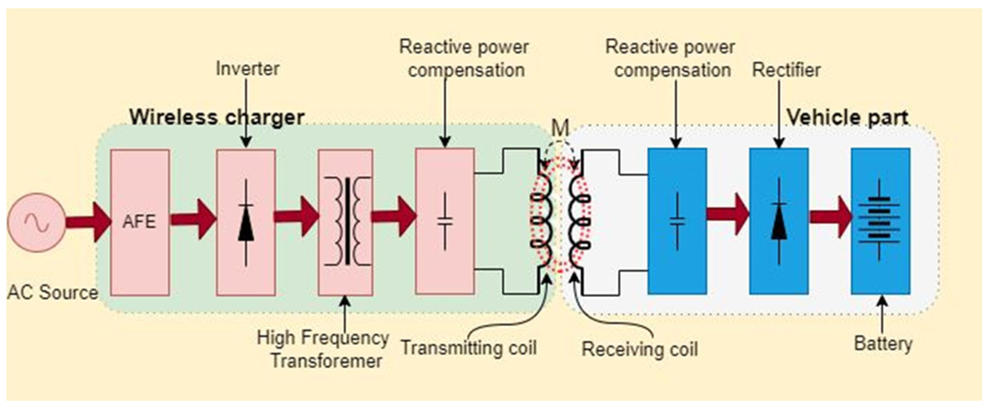
1.1. Outline of WPT System for EVs
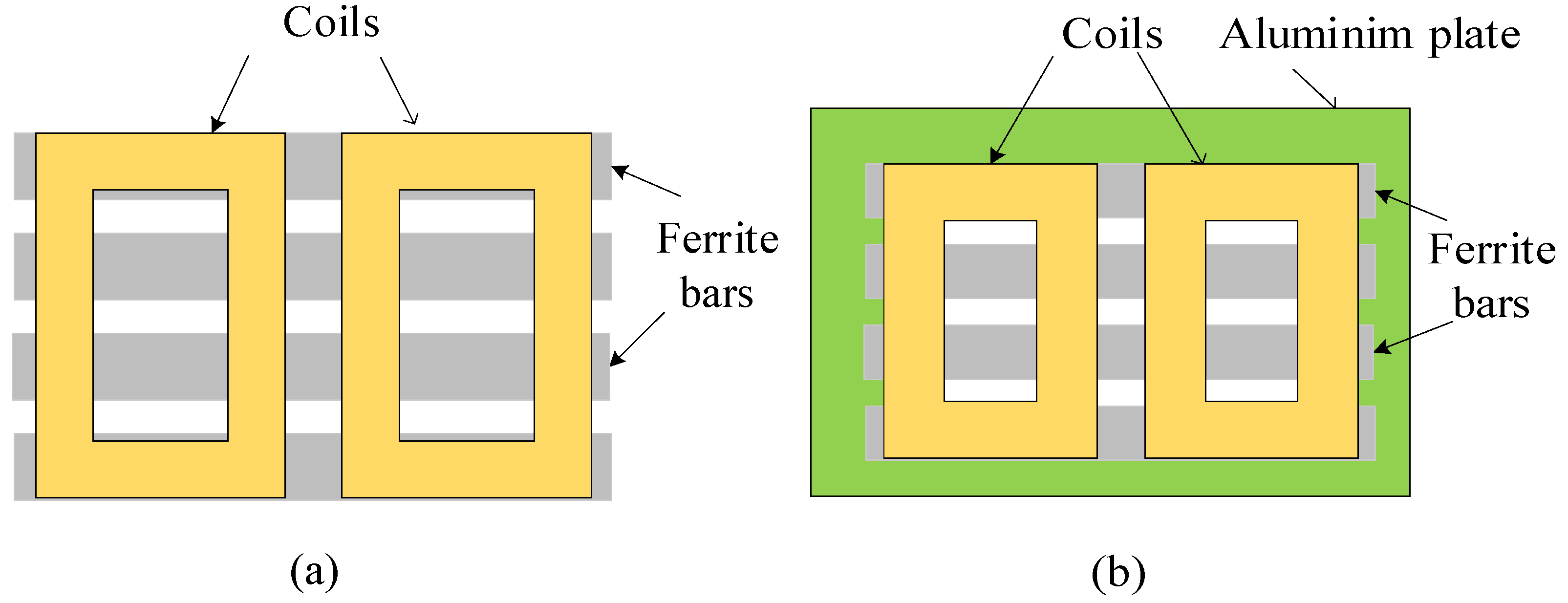
1.2. Wireless Charging Power Pad
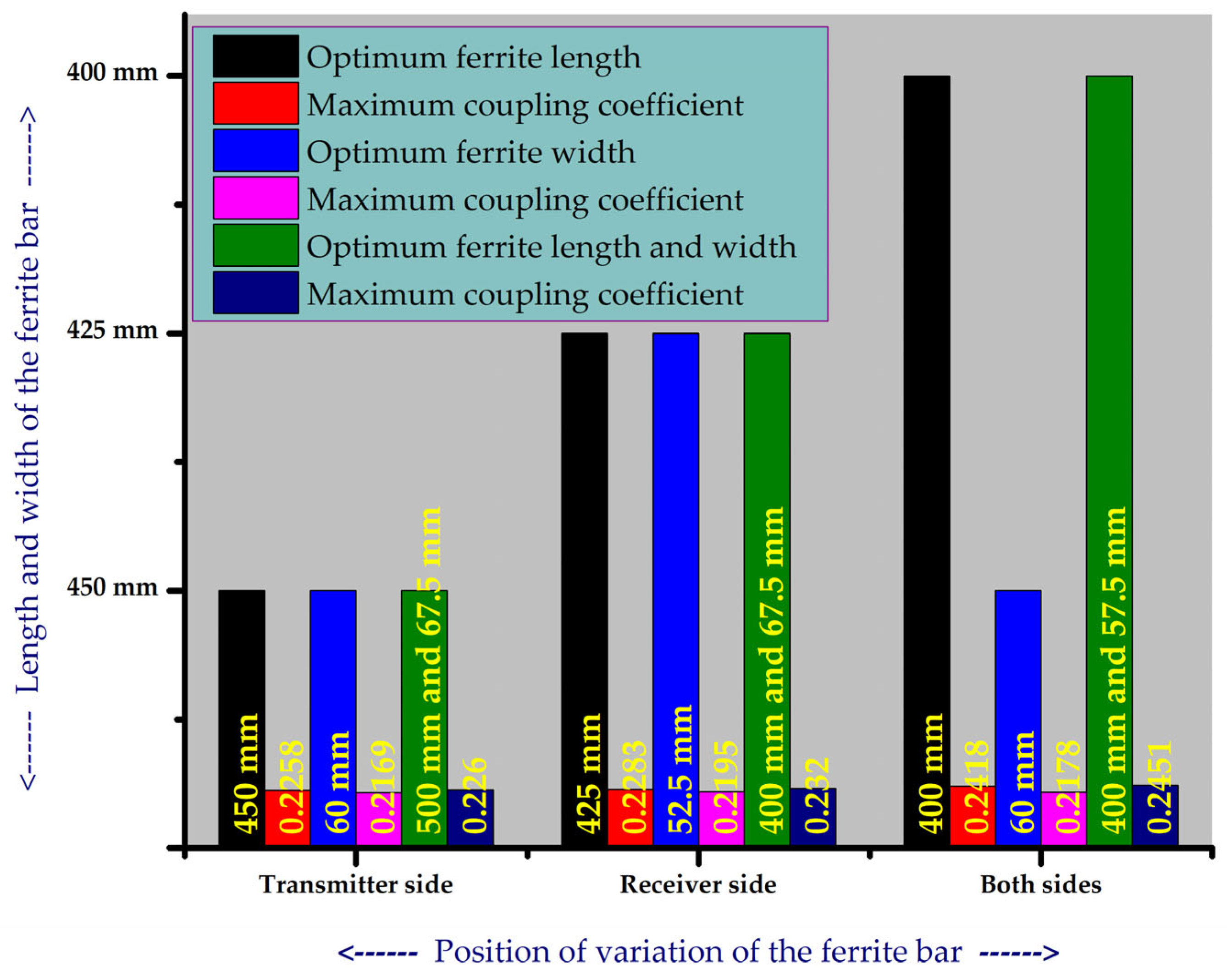
- Case 1: The length of the ferrite bars is varied at Tx, Rx, and both Tx and Rx by maintaining a constant ferrite width for the optimal value of length to maximize the value of ‘k’;
- Case 2: The width of the ferrite bars is varied at Tx, Rx, and both Tx and Rx by maintaining a constant ferrite length for the optimal value of width to maximize the value of ‘k’;
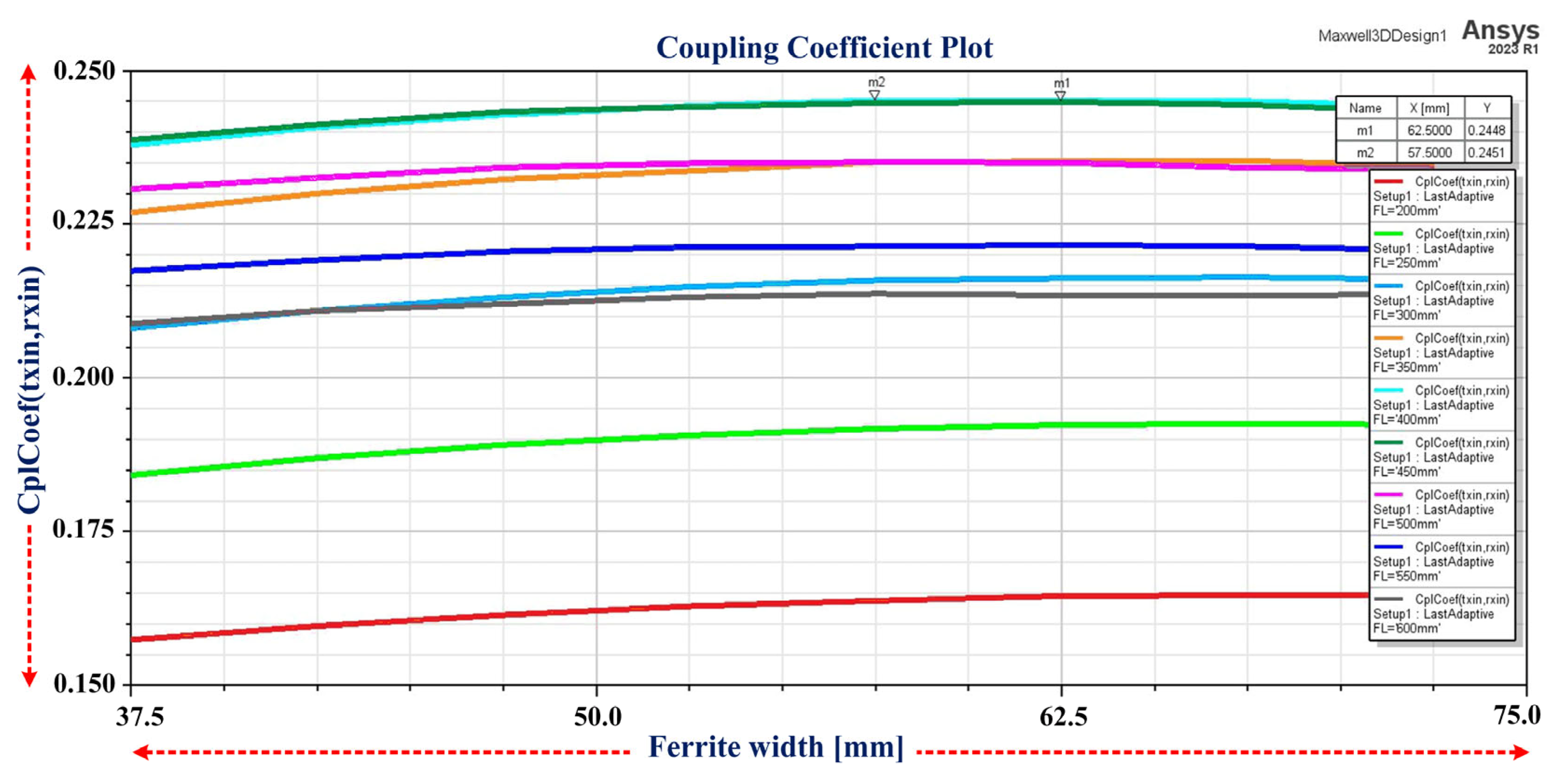
- Case 3: Both the length and width of the ferrite bars are varied at Tx, Rx, and both Tx and Rx for the optimal values of length and width to maximize the value of ‘k’.

| Reference | Type of Coil Pad on Tx-Rx Sides | Type of Core on Tx-Rx Sides | Inference |
|---|---|---|---|
| [26] | Case 1: Both sides—Rectangular Case 2: Both sides—DD | Both sides—I-type ferrite bars | Objective: Comparing rectangular winding design to DD winding in IPT coils with the same outer dimensions, the main merits and demerits are discussed using Pareto analysis. Shortfall: The effect of the change in dimensions of I-type ferrite bars is not considered. |
| [9] | Case 1: Both sides—Circular Case 2: Both sides—Rectangular Case 3: Both sides—DD Case 4: Tx side—DD and Rx side—DDQ | Both sides—I-type ferrite bars | Objective: The authors presented a multi-objective optimization framework to evaluate the performance of four coupler topologies. Presented merits, demerits, and trade-offs in key parameters such as efficiency, power density, misalignment tolerance, and stray field for all geometries. Shortfall: The effect of the change in dimensions of I-type ferrite bars is not considered. |
| [17] | Case 1: Both sides—DD | Both sides—I-type ferrite bars | Objective: Proposed optimization of the horizontal spacing of DD coils and the length of cores. Shortfall: On each side, six I-type ferrite bars are used and only the length of the ferrite bar is varied. |
| [23] | Case 1: Only on Tx side—DD | Only on Tx side—I-type ferrite bars | Objective: Introduced a multi-objective optimization method for I-type ferrite bars with a primary DD pad in inductive power transfer systems while considering four I-type ferrite bars and three I-type ferrite bars. With the utilization of nondominated sorting genetic algorithm II, the DD pad structure is optimized to achieve a high coupling coefficient and minimize worst-case stray leakage magnetic fields. Shortfall: Simultaneous variation in length and width is not considered. The length and width are varied individually only on the Tx side. |
| [27] | Case 1: Both sides—DD | Tx side—I-type ferrite Rx side—rectangular plate | Objective: Achieved the most effective mutual inductance value to obtain the maximum efficiency when the distance between ferrite bars is 15 mm. Shortfall: 25 I-type ferrite bars are used at the transmitter side, and only the gap between ferrite bars is varied. |
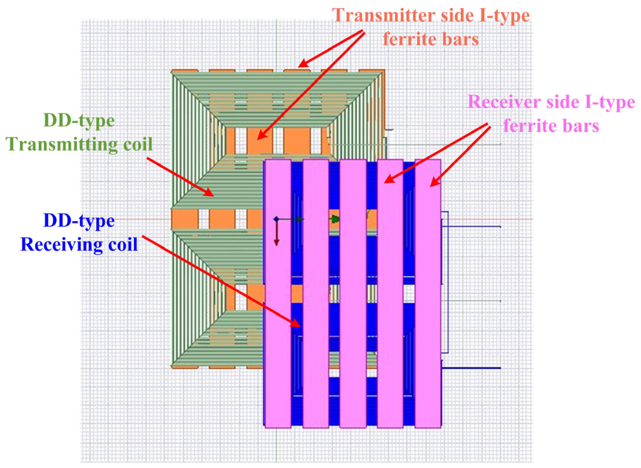
| Proposed | Case 1: Both sides—DD | Both sides—I-Type ferrite bars | Objective: In this study of DD coils, six I-type ferrite bars on the transmitter side and five I-type ferrite bars on the receiver side are considered for optimal design. Highlights: The length and width varied on the Tx and Rx sides, as well as simultaneously on both sides, to achieve the best coupling coefficient. |
2. Methodology and System Model
2.1. Methodology
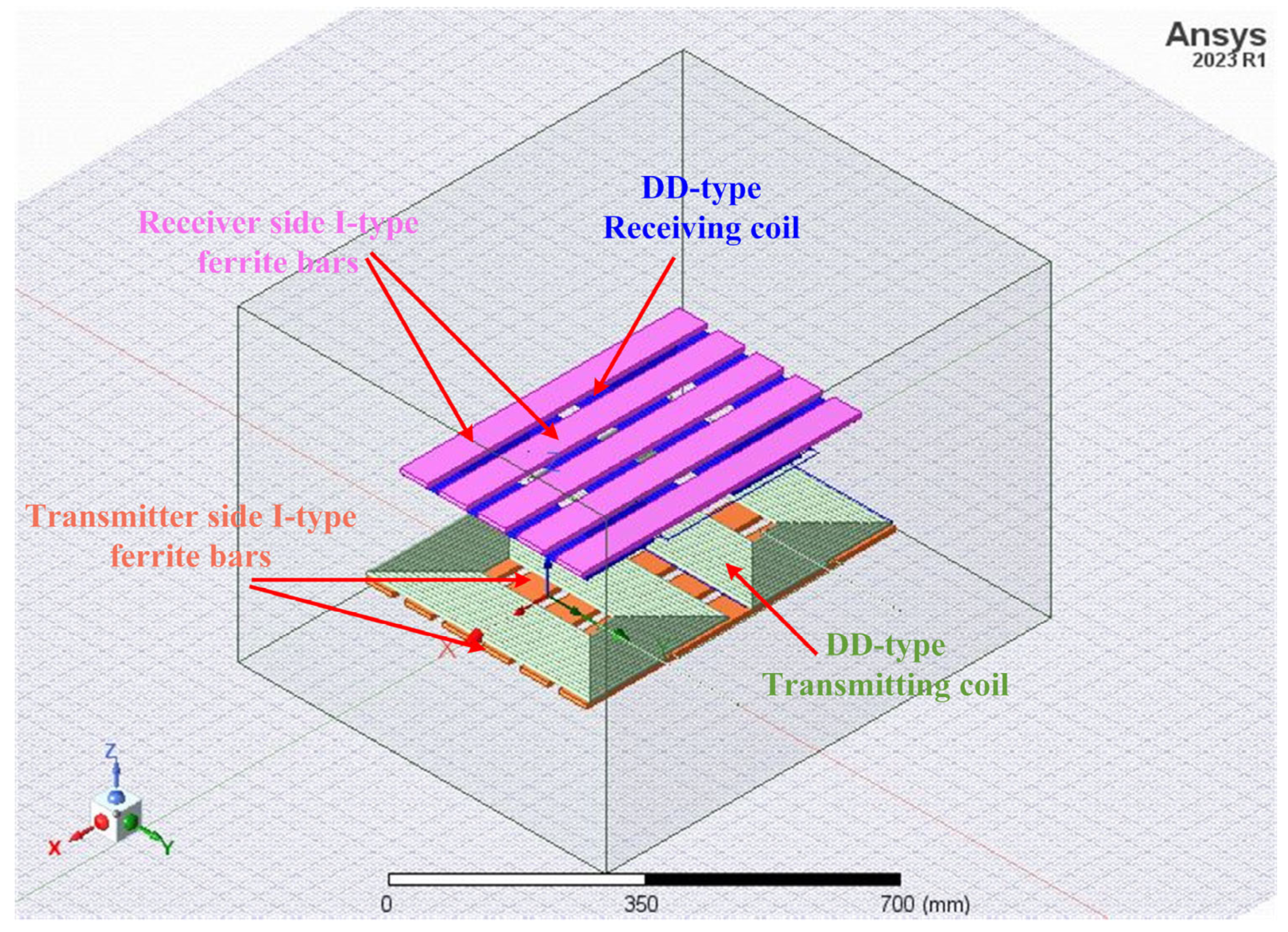
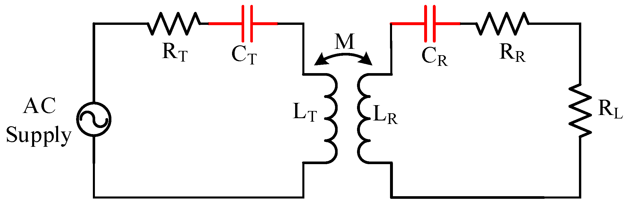
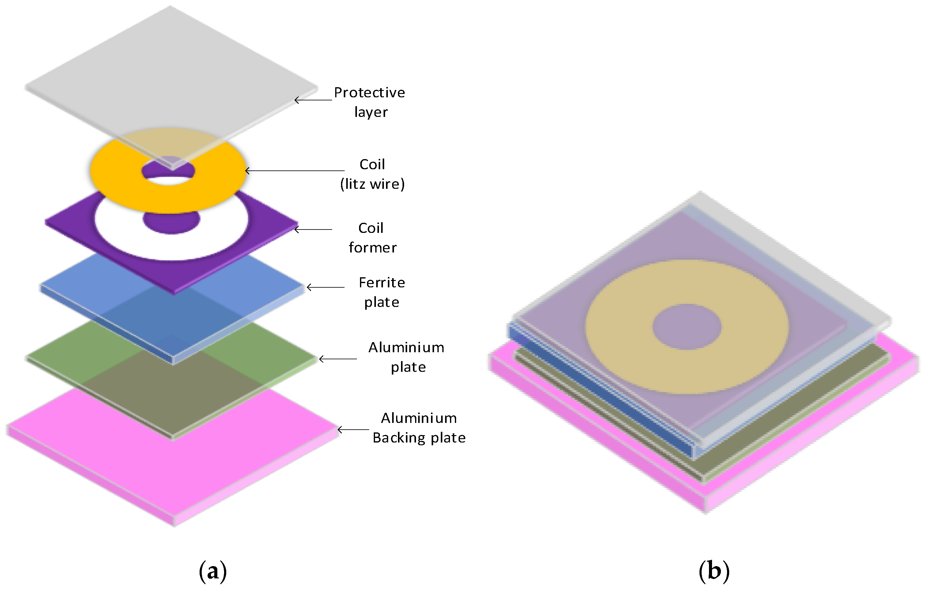
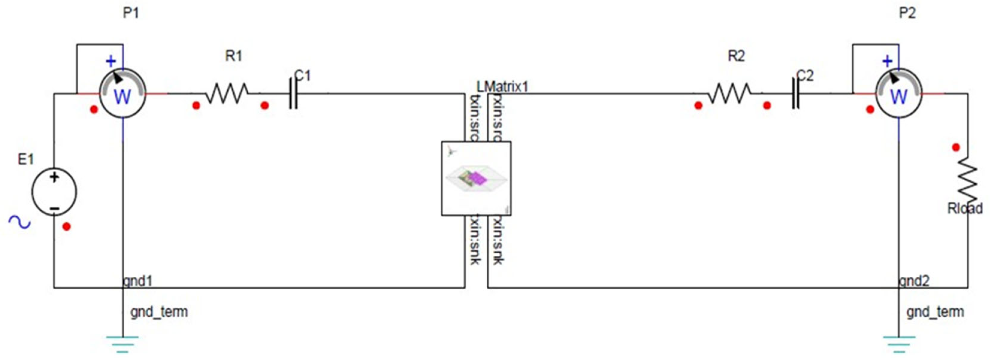
2.2. System Model: DD Coil Setup for ICWCS
3. Analysis of the Proposed Structure
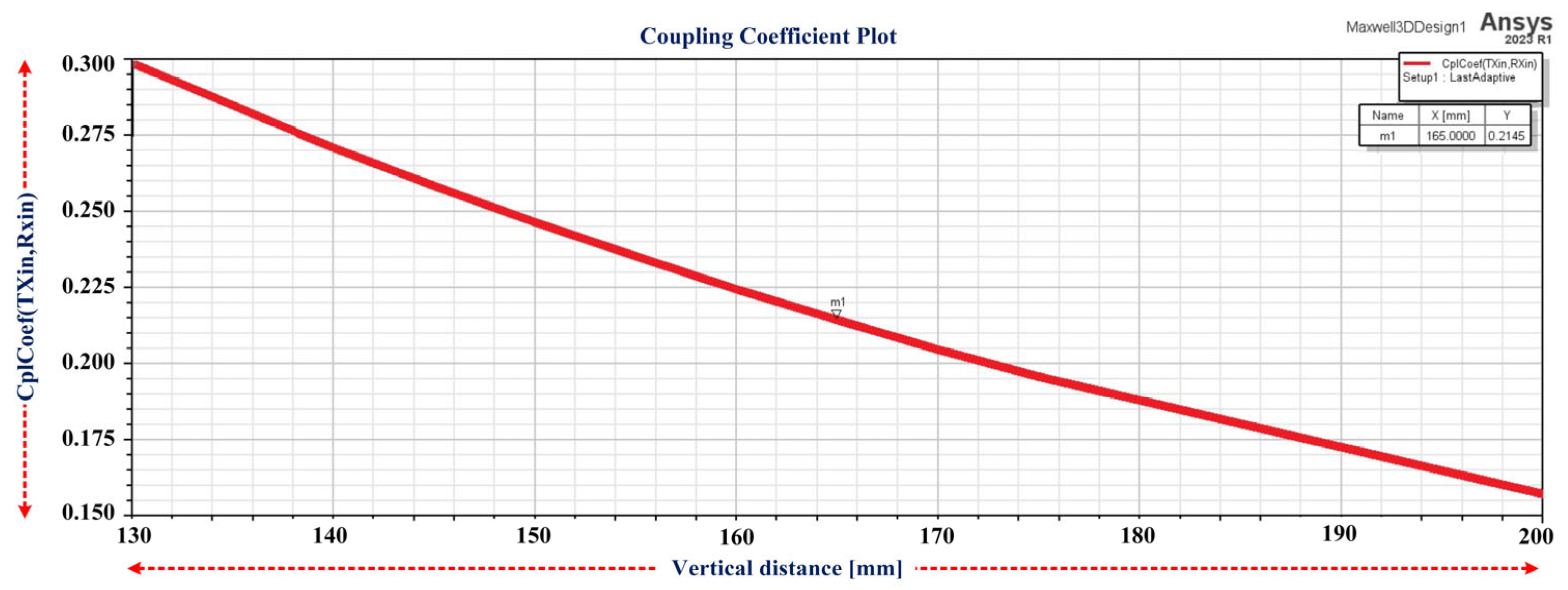
3.1. Performance of the ICWCS at Different Misalignments

3.2. Optimization of Ferrite Core Dimensions
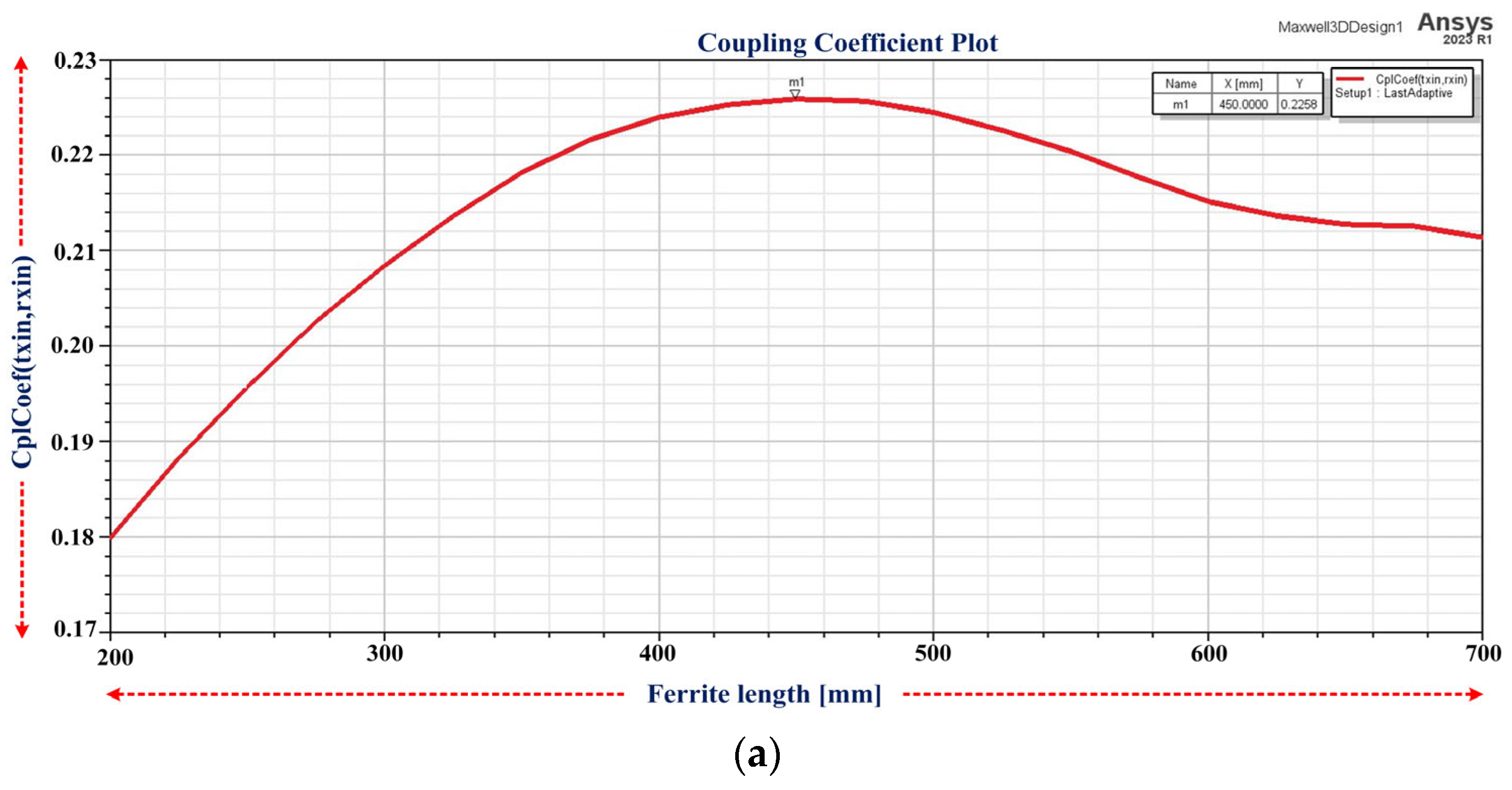
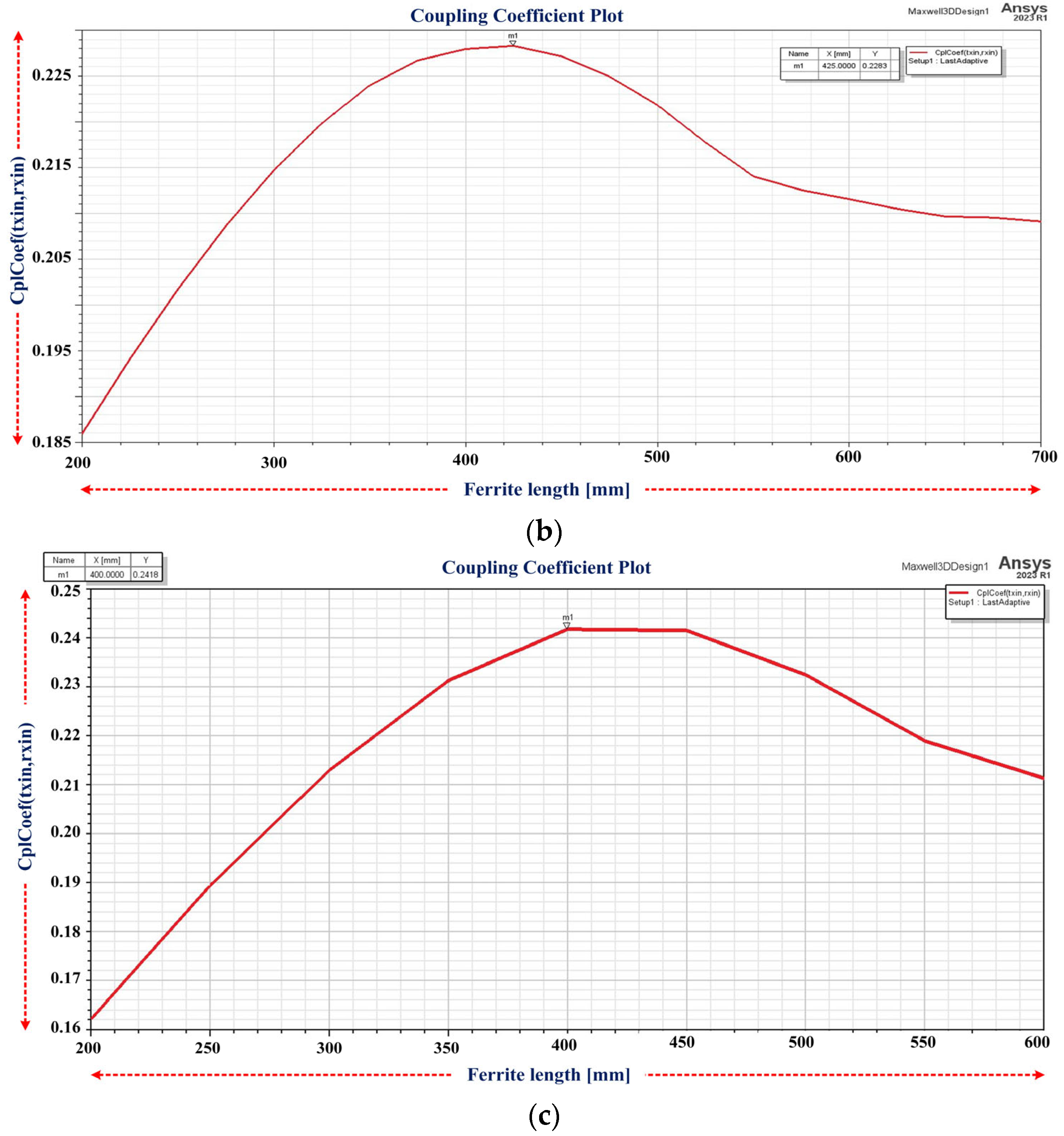
3.2.1. Case 1: Constant Ferrite Width: 52.5 mm
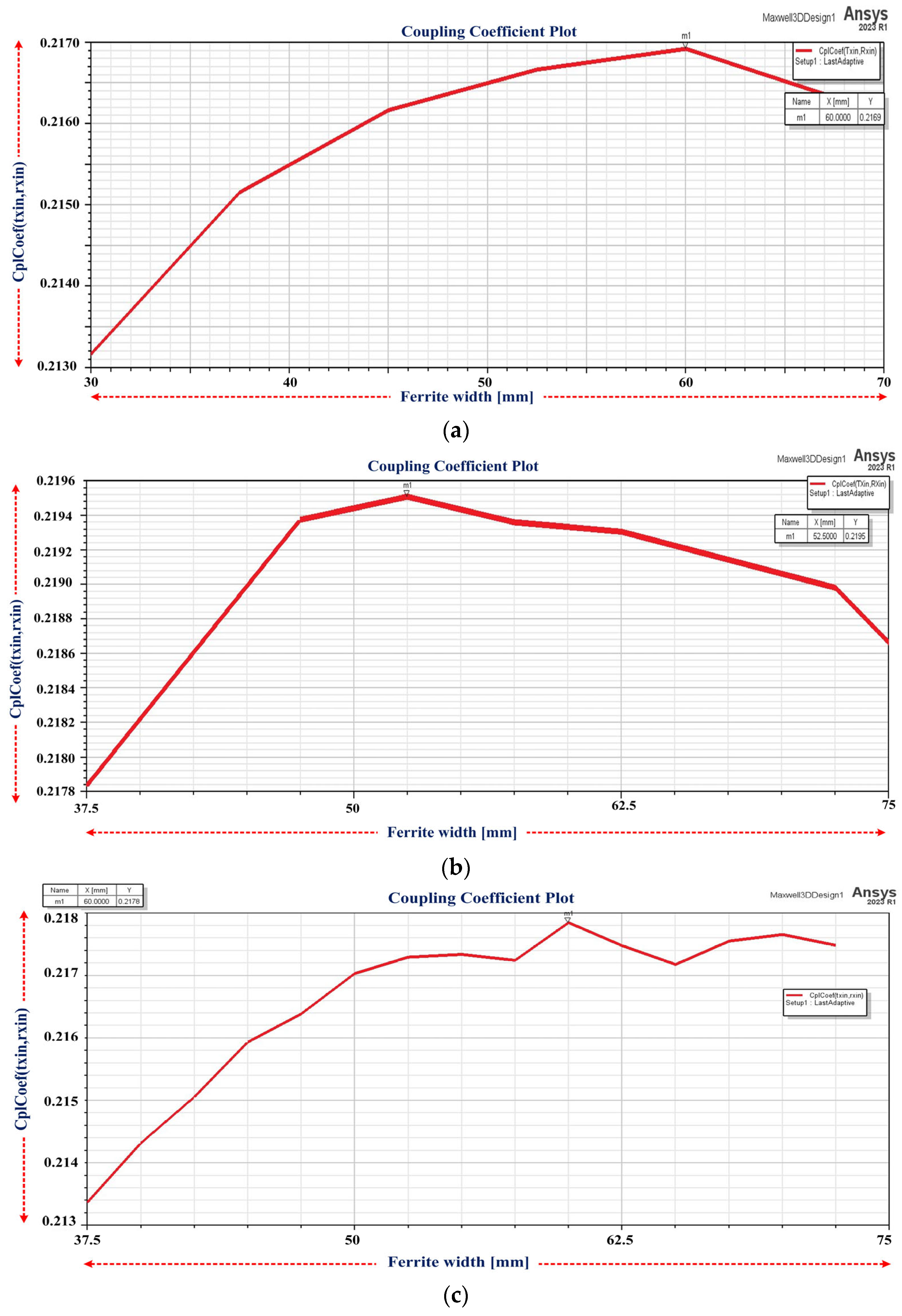
3.2.2. Case 2: Constant Ferrite Length at the Transmitter and Receiver Sides Is 600 mm and 540 mm, Respectively
3.2.3. Case 3: Ferrite Length and Width Vary Simultaneously
4. Conclusions
- 0.2418 at 400 mm of ferrite length when varied on both sides, keeping the width invariable at 52.5 mm;
- 0.2195 at 52.5 mm of ferrite width when varied on the Rx side, keeping the length of 600 mm on the Tx side and of 540 mm on the Rx side;
- 0.2451 at 400 mm of ferrite length and 57.5 mm of ferrite width when ferrite length and width are varied on both sides.
Author Contributions
Funding
Data Availability Statement
Acknowledgments
Conflicts of Interest
Abbreviations
| AC | Alternating current |
| DC | Direct current |
| EV | Electric vehicle |
| WC | Wireless charging |
| WCS | Wireless charging system |
| DWCS | Dynamic wireless charging system |
| ICWCS | Inductively coupled wireless charging system |
| DD | Double-D |
| 3D | Three-dimensional |
| FEM | Finite element technique |
| SAE | Society of Automotive Engineers |
| HFT | High frequency transformer |
| IPT | Inductive power transfer |
| WPT | Wireless power transfer |
| Tx | Transmitting coil |
| Rx | Receiving coil |
| M | Mutual inductance |
| k | Coupling coefficient |
| LT | Self-inductance of Tx |
| LR | Self-inductance of Rx |
| CT | Capacitance of Tx |
| CR | Capacitance of Rx |
| RT | Resistance of Tx |
| RR | Resistance of Rx |
| RL | Load resistance |
| ICNIRP | International Commission on Non-Ionizing Radiation Protection |
| km | Maximum coupling coefficient |
References
- Catrysse, M.; Hermans, B.; Puers, R. An inductive power system with integrated bi-directional data-transmission. Sens. Actuators A Phys. 2004, 115, 221–229. [Google Scholar] [CrossRef]
- Mathesh, G.; Saravanakumar, R. A Novel Intelligent Controller-Based Power Management System with Instantaneous Reference Current in Hybrid Energy-Fed Electric Vehicle. IEEE Access 2023, 11, 137849–137865. [Google Scholar] [CrossRef]
- Mohamed, A.A.S.; Shaier, A.A.; Metwally, H.; Selem, S.I. An Overview of Dynamic Inductive Charging for Electric Vehicles. Energies 2022, 15, 5613. [Google Scholar] [CrossRef]
- Vaka, R.; Keshri, R.K. Design considerations for enhanced coupling coefficient and misalignment tolerance using asymmetrical circular coils for WPT system. Arab. J. Sci. Eng. 2019, 44, 1949–1959. [Google Scholar] [CrossRef]
- Bouanou, T.; Fadil, H.E.; Lassioui, A.; Bentalhik, I.; Koundi, M.; Jeilani, E.S. Design Methodology and Circuit Analysis of Wireless Power Transfer Systems Applied to Electric Vehicles Wireless Chargers. World Electr. Veh. J. 2023, 14, 117. [Google Scholar] [CrossRef]
- Chakibanda, V.; Komanapalli, V.L. Optimization in Magnetic Coupler Design for Inductively Coupled Wireless Charging of Electric Vehicle: A Review. Arab. J. Sci. Eng. 2023, 48, 14257–14294. [Google Scholar] [CrossRef]
- Economic and Environmental Sustainability of Dynamic Wireless Power Transfer for Electric Vehicles Supporting Reduction of Local Air Pollutant Emissions—ScienceDirect. Available online: https://www.sciencedirect.com/science/article/pii/S1364032120308212 (accessed on 7 July 2023).
- Ushijima-Mwesigwa, H.; Khan, M.Z.; Chowdhury, M.A.; Safro, I. Optimal installation for electric vehicle wireless charging lanes. arXiv 2017, arXiv:1704.01022. [Google Scholar]
- Bandyopadhyay, S.; Venugopal, P.; Dong, J.; Bauer, P. Comparison of magnetic couplers for ipt-based EV charging using multi-objective optimization. IEEE Trans. Veh. Technol. 2019, 68, 5416–5429. [Google Scholar] [CrossRef]
- Kadem, K.; Bensetti, M.; Le Bihan, Y.; Labouré, E.; Debbou, M. Optimal Coupler Topology for Dynamic Wireless Power Transfer forElectric Vehicle. Energies 2021, 14, 3983. [Google Scholar] [CrossRef]
- Budhia, M.; Covic, G.; Boys, J. A new IPT magnetic coupler for electric vehicle charging systems. In Proceedings of the IECON 2010—36th Annual Conference on IEEE Industrial Electronics Society, Glendale, AZ, USA, 7–10 November 2010; pp. 2487–2492. [Google Scholar]
- Cheng, Y.; Shu, Y. A new analytical calculation of the mutual inductance of the coaxial spiral rectangular coils. IEEE Trans. Magn. 2014, 50, 7026806. [Google Scholar] [CrossRef]
- Aissaoui, M.; Allag, H.; Yonnet, J.P. Mutual inductance and interaction calculation between conductor or coil of rectangular cross section and parallel piped permanent magnet. IEEE Trans. Magn. 2014, 50, 7027704. [Google Scholar] [CrossRef]
- Smeets, J.P.C.; Overboom, T.T.; Jansen, J.W.; Lomonova, E.A. Three-dimensional magnetic field modeling for coupling calculation between air-cored rectangular coils. IEEE Trans. Magn. 2011, 47, 2935–2938. [Google Scholar] [CrossRef]
- Kushwaha, B.K.; Rituraj, G.; Kumar, P. 3d analytical model for computation of mutual inductance for different misalignments with shielding in wireless power transfer system. IEEE Trans. Transp. Electrif. 2017, 3, 332–342. [Google Scholar] [CrossRef]
- Joy, E.; Dalal, A.; Kumar, P. Accurate computation of mutual inductance of two air core square coils with lateral and angular misalignments in a flat planar surface. IEEE Trans. Magn. 2014, 50, 7000209. [Google Scholar] [CrossRef]
- Yang, Z.; Chen, Y.; Yang, D.; Du, W.; He, G.; Zhang, X.; Xu, C.; Wang, W. Research on parameter optimization of Double-D coils for electric vehicle wireless charging based on magnetic circuit analysis. IEICE Electron. Express 2020, 17, 20200067. [Google Scholar] [CrossRef]
- Hassanein, W.; Enany, M.A.; Shaier, A.A.; Ahmed, A.A. Performance analysis of rectangular and double-D transmitters with various receivers for electric vehicle static charging. Alex. Eng. J. 2023, 78, 438–452. [Google Scholar] [CrossRef]
- Yang, Y.; Cui, J.; Cui, X. Design and Analysis of Magnetic Coils for Optimizing the Coupling Coefficient in an Electric Vehicle Wireless Power Transfer System. Energies 2020, 13, 4143. [Google Scholar] [CrossRef]
- Chi, F.; Wang, P.; Sun, C.; Wu, Y.; Dou, Z.; Xu, C.; Wang, S.; Wang, W. Research on Optimization of Horizontal Omnidirectional Misalignment Tolerance of WPT Based on Double D Coupler. Electronics 2022, 11, 2163. [Google Scholar] [CrossRef]
- Bensetti, M.; Kadem, K.; Pei, Y.; Le Bihan, Y.; Labouré, E.; Pichon, L. Parametric Optimization of Ferrite Structure Used for Dynamic Wireless Power Transfer for 3 kW Electric Vehicle. Energies 2023, 16, 5439. [Google Scholar] [CrossRef]
- Choi, B.-G.; Kim, Y.-S. New Structure Design of Ferrite Cores for Wireless Electric Vehicle Charging by Machine Learning. IEEE Trans. Ind. Electron. 2021, 68, 12162–12172. [Google Scholar] [CrossRef]
- Luo, Z.; Wei, X.; Pearce, M.G.S.; Covic, G.A. Multiobjective optimization of inductive power transfer double-D pads for electric vehicles. IEEE Trans. Power Electron. 2020, 36, 5135–5146. [Google Scholar] [CrossRef]
- Mohammad, M.; Choi, S. Optimization of ferrite core to reduce the core loss in double-D pad of wireless charging system for electric vehicles. In Proceedings of the 2018 IEEE Applied Power Electronics Conference and Exposition (APEC), San Antonio, TX, USA, 4–8 March 2018; pp. 1350–1356. [Google Scholar]
- Gu, B.S.; Dharmakeerthi, T.; Kim, S.; O’Sullivan, M.J.; Covic, G.A. Optimised Magnetic Core Layer in Inductive Power Transfer Pad for Electric Vehicle Charging. IEEE Trans. Power Electron. 2023, 38, 11964–11973. [Google Scholar] [CrossRef]
- Bosshard, R.; Iruretagoyena, U.; Kolar, J.W. Comprehensive evaluation of rectangular and double-D coil geometry for 50 kW/85 kHz IPT system. IEEE J. Emerg. Sel. Top. Power Electron. 2016, 4, 1406–1415. [Google Scholar] [CrossRef]
- Shaier, A.A.; Mohamed, A.A.; Metwally, H.; Selem, S.I. New design of high-power in-motion inductive charger for low power pulsation. Sci. Rep. 2023, 13, 17838. [Google Scholar] [CrossRef] [PubMed]
- SAE TIR J2954_201605; Wireless Power Transfer for Light-Duty Plug-in/Electric Vehicle and Alignment Methodology. SAE International: Warrendale, PA, USA, 2016.
- Luo, Z.; Li, X.; Jiang, C.; Li, Z.; Long, T. Permeability-adjustable nanocrystalline flake ribbon in customized high-frequency magnetic components. IEEE Trans. Power Electron. 2023, 39, 3477–3485. [Google Scholar] [CrossRef]
- Ou, J.; Liu, Y.; Breining, P.; Schiefer, M.; Doppelbauer, M. Experimental study of the amorphous magnetic material for high-speed sleeve-free PM rotor application. IEEE Trans. Ind. Electron. 2019, 67, 4422–4432. [Google Scholar] [CrossRef]
- International Commission on Non-Ionizing Radiation Protection. Guidelines for limiting exposure to time-varying electric and magnetic fields (1 Hz to 100 kHz). Health Phys. 2010, 99, 818–836. [Google Scholar] [CrossRef]


| Position | Horizontal Alignment | Coupling Coefficient (km) | Maximum Efficiency (%) |
|---|---|---|---|
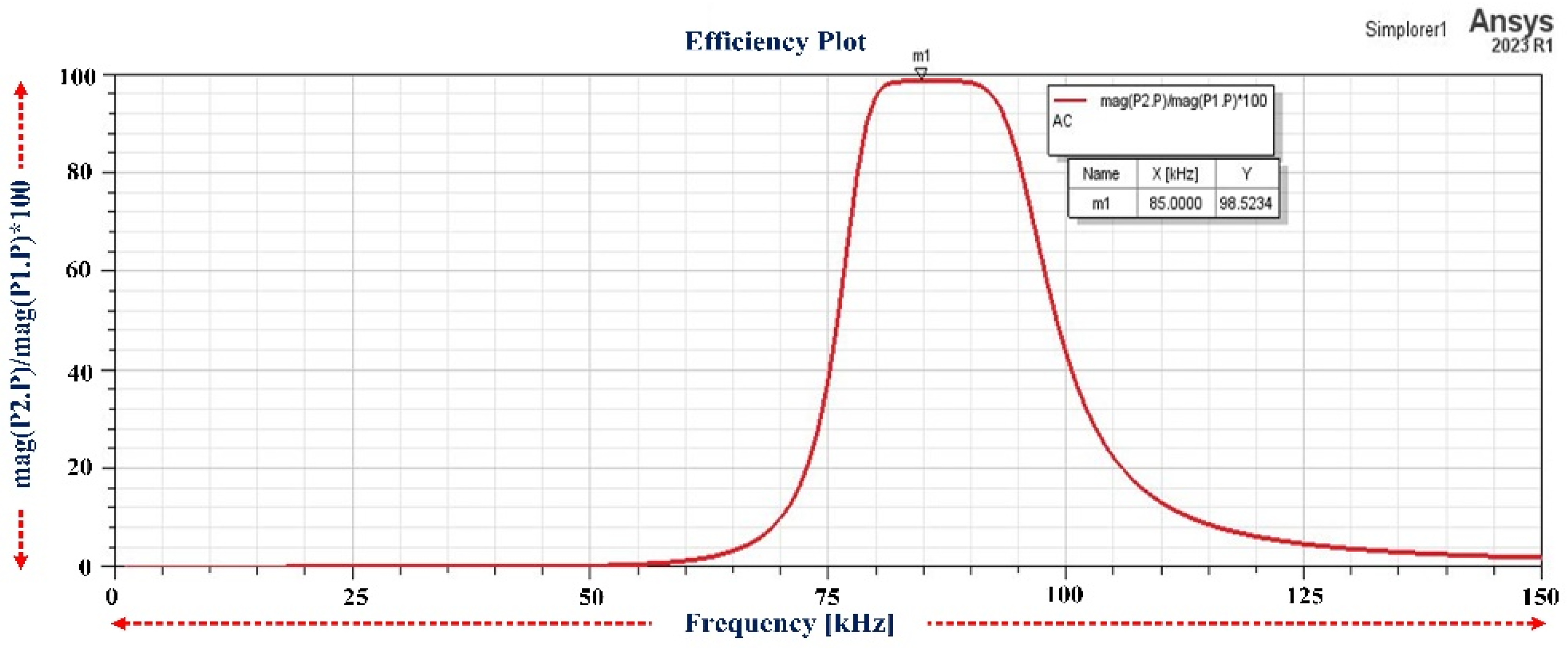
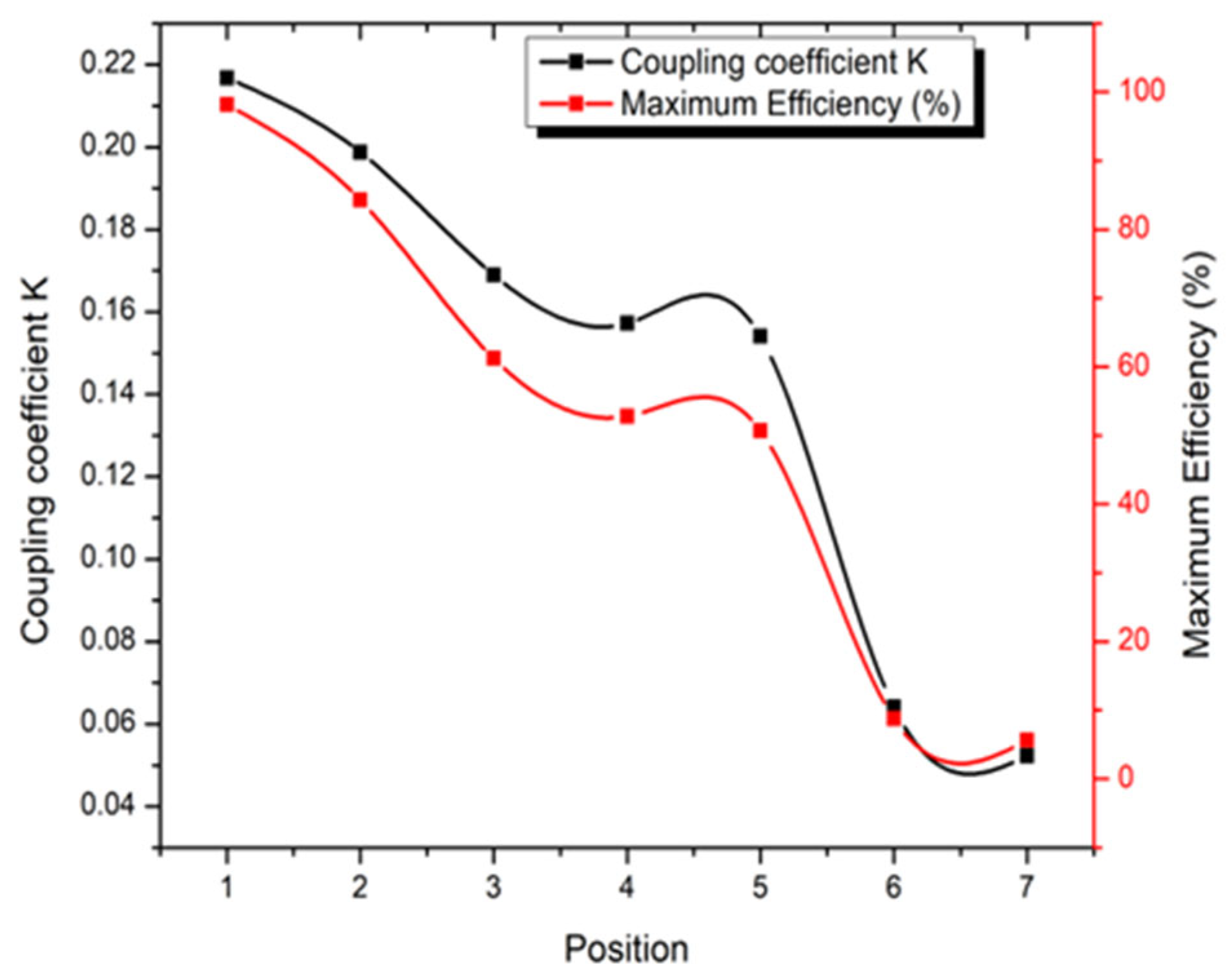
| 1 | X = 0 mm, Y = 0 mm | 0.2168 | 98.52 |
| 2 | X = 0 mm, Y = 75 mm | 0.1988 | 84.29 |
| 3 | X = 75 mm, Y = 0 mm | 0.1690 | 61.22 |
| 4 | X = 75 mm, Y = 75 mm | 0.1572 | 52.81 |
| 5 | X = 0 mm, Y = 150 mm | 0.1541 | 50.68 |
| 6 | X = 150 mm, Y = 0 mm | 0.0641 | 8.81 |
| 7 | X = 150 mm, Y = 150 mm | 0.0523 | 5.61 |
| Ferrite Length Varied at | Optimum Ferrite Length | Maximum Coupling Coefficient (km) |
|---|---|---|
| Transmitter side | 450 mm | 0.2258 |
| Receiver side | 425 mm | 0.2283 |
| Both sides | 400 mm | 0.2418 |
| Ferrite Width Varied at | Optimum Ferrite Width | Maximum Coupling Coefficient (km) |
|---|---|---|
| Transmitter side | 60 mm | 0.2169 |
| Receiver side | 52.5 mm | 0.2195 |
| Both sides | 60 mm | 0.2178 |
| Ferrite Length and Width Varied at | Optimum Ferrite Length and Width | Maximum Coupling Coefficient (km) |
|---|---|---|
| Transmitter side | 500 mm and 67.5 mm | 0.2260 |
| Receiver side | 400 mm and 67.5 mm | 0.2320 |
| Both sides | 400 mm and 57.5 mm | 0.2451 |
Disclaimer/Publisher’s Note: The statements, opinions and data contained in all publications are solely those of the individual author(s) and contributor(s) and not of MDPI and/or the editor(s). MDPI and/or the editor(s) disclaim responsibility for any injury to people or property resulting from any ideas, methods, instructions or products referred to in the content. |
© 2024 by the authors. Licensee MDPI, Basel, Switzerland. This article is an open access article distributed under the terms and conditions of the Creative Commons Attribution (CC BY) license (https://creativecommons.org/licenses/by/4.0/).
Share and Cite
Chakibanda, V.; Komanapalli, V.L.N. Coil Parameter Analysis for Inductively Coupled Wireless Charging for Electric Vehicles. Vehicles 2024, 6, 468-483. https://doi.org/10.3390/vehicles6010021
Chakibanda V, Komanapalli VLN. Coil Parameter Analysis for Inductively Coupled Wireless Charging for Electric Vehicles. Vehicles. 2024; 6(1):468-483. https://doi.org/10.3390/vehicles6010021
Chicago/Turabian StyleChakibanda, Viswanath, and Venkata Lakshmi Narayana Komanapalli. 2024. "Coil Parameter Analysis for Inductively Coupled Wireless Charging for Electric Vehicles" Vehicles 6, no. 1: 468-483. https://doi.org/10.3390/vehicles6010021
APA StyleChakibanda, V., & Komanapalli, V. L. N. (2024). Coil Parameter Analysis for Inductively Coupled Wireless Charging for Electric Vehicles. Vehicles, 6(1), 468-483. https://doi.org/10.3390/vehicles6010021