1. Introduction
In 2015, 195 parties agreed to drastically reduce CO
emissions in the upcoming years by signing the Paris Agreement [
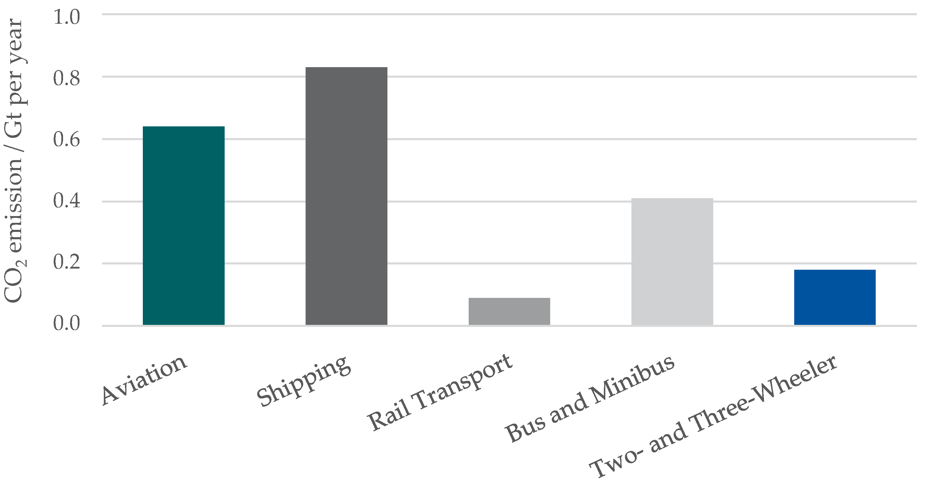
1]. To achieve the defined goals, measures in different sectors must be taken. With 7.2 Gt of CO
, the transportation sector represented
of the global CO
emissions in 2020. In addition to light and heavy duty vehicles, 2.1 Gt of CO
are emitted in other fields of transportation (
Figure 1) [
2], which offers a substantial potential for emission reduction. Facing increasing legal restrictions, the automotive industry is highly focussed on electrification, with technologies ranging from mild-hybrid powertrains to battery electric vehicles [
3,
4]. This enables CO
reduction for passenger cars, but in Asian countries such as India, the vehicle market is dominated by scooters with a market share of
(in 2020) [
5]. Local emissions are predominantly emitted by these vehicles with a limited focus on electrification. To ensure good driveability, high comfort and low costs, most of these vehicles are equipped with a rubber-belt continuous variable transmission (CVT) for coupling the internal combustion engine (ICE) and the rear wheel. However, studies show that the average efficiency of state-of-the-art CVTs typically ranges from
to
[
6]. This is mainly caused by mechanical friction between the belt and the cone plates as well as energy losses due to buckling of the belt. This results in unnecessary high fuel consumption and, thus, CO
emissions.
Fully electric scooters could be a solution, but studies reveal that limited range, performance, charging infrastructure and increased component costs are highly limiting the market penetration [
7,
8]. Furthermore, hybrid powertrains are even less popular due to system complexity and costs, respectively, although they could reduce local emissions in combination with providing an increased range [
9].
Many hybrid drives are known from the automotive industry, but they are not economically feasible for use in scooters and other light vehicles. Complex powertrain topologies involving transmissions with active shifting elements or multiple electric motors, as well as different sensors and actuators, increase the price and weight of such drive units.
However, the scooter industry has also developed a number of hybrid powertrains over the last few years. The first commercial hybrid powertrain in a scooter application was launched by Piaggio in 2009 with a three-wheeled scooter called MP3 Hybrid. It has an electric motor coupled to the driven axle via a reduction gear. The internal combustion engine is connected to a conventional CVT and can be disengaged using a clutch. The vehicle can travel up to 20
and has a top speed of
= 30
in pure electric mode. While the electric motor is connected to the axle via an efficient spur gear, the combustion engine is still connected via the inefficient CVT. As a result, the saving potential in hybrid mode is very limited [
10].
Since 2018, Honda has been offering a hybrid scooter named PCX eHEV. The powertrain is similar to a conventional scooter, in which a CVT connects the ICE to the rear wheel. Additionally, an electric motor is attached directly to the crankshaft of the ICE. This allows one to crank the ICE, charge the battery, provide electricity to the vehicle electronics and feed energy to the battery during deceleration or electric torque assist during acceleration. Pure electric driving is not possible with this system, which makes it a mild hybrid. The PCX-Hybrid achieves a fuel consumption improvement of about 9% compared with the conventional PCX125 scooter [
11,
12].
In addition to commercial applications, several research projects have investigated various hybrid concepts for use in scooters. A powertrain concept presented by Sheu and Hsu in 2006 combines an electric motor with an internal combustion engine using one-way clutches, chain drives and a CVT. The powertrain uses a
petrol engine and a
direct current (DC) electric motor and has been tested on a dynamometer [
13].
Recent research by IIT Madras compares different parallel hybrid topologies and concludes that a P3 configuration with the electric motor on the rear axle offers the highest saving potential of the common parallel hybrid topologies [
14].
Another hybrid drive, introduced by Sheu in 2008, uses a combination of two planetary gear sets to combine an electric DC motor with a
two-stroke gasoline engine. This is achieved by using three active clutches, one of which acts as a brake. Due to the different switching states of the clutches, 36 combinations are theoretically possible [
15]. While combining two planetary gearsets increases complexity, it enables excellent driving comfort and highly efficient power transmission [
16,
17]. A similar and well-known automotive application is Toyota’s Hybrid Synergy Drive, which uses two electric motors and a planetary gear set to distribute the power of the ICE to a mechanical and an electrical path [
18]. Due to high costs for two electric motors and IP constraints, this concept has not been used in commercial two-wheeler applications.
However, there is currently no hybrid system available without a CVT that provides good driveability, low fuel consumption as well as little system complexity and, thus, low costs.
This contribution introduces a hybrid transmission combining relevant hybrid functionalities such as electric driving, electric torque assist and recuperation, while decreasing fuel consumption compared with conventional scooters equipped with CVTs. Compared with existing and previously investigated hybrid powertrain architectures, the proposed hybrid transmission reduces the powertrain complexity using a minimal number of components in order to potentially enable a cost competitive solution to conventional and electric powertrains. First, the mechanical concept, operating strategy and the design of a demonstrator vehicle are explained thoroughly. This contribution ends with an experimental validation of the proposed hybrid powertrain concept, proving the basic functionality and fulfilment of the required full hybrid functions.
2. Hybrid Powertrain Concept
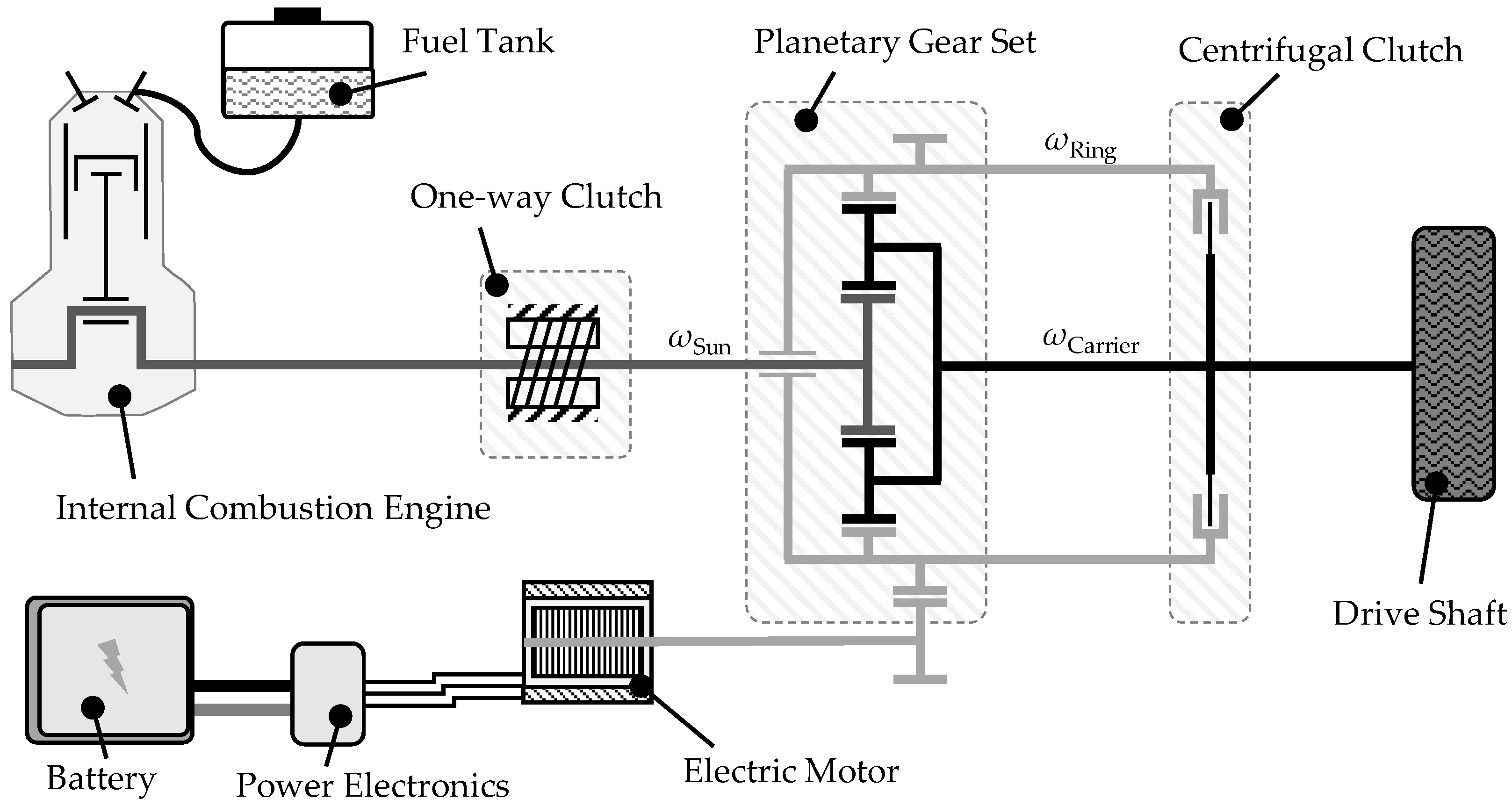
The hybrid powertrain concept presented in this work is based on a combination of an ICE and an electric powertrain consisting of an electric motor, an inverter and a battery. The ICE, the electric motor and the drive shaft are coupled using a single planetary gear set (PGS) from the robotics industry.
In contrast to existing concepts, the proposed powertrain is characterized by the elimination of as many active components as possible. This reduces system complexity in development and manufacturing as well as promises competitive costs, even for a scooter application.
Figure 2 shows a possible mechanical design of the proposed hybrid powertrain [
19].
2.1. Variable Ratio Mode
In the configuration shown in
Figure 2, the ICE is coupled to the sun gear and the electric motor is connected to the ring gear. The drive shaft is connected to the planet carrier and can drive the axle directly with a spur gear, tooth belt or chain drive. If the centrifugal clutch is unlocked, the planetary gearset is used in three-shaft operation. The determining factor for the operating condition is the rotational speed of the electric motor
, which, in combination with the drive shaft speed
and the carrier train ratio
i, defines the rotational speed of the combustion engine
according to the Willis equation [
20].
The torque at the drive shaft of the PGS and the resulting supporting torque, which the electric motor must impose, are defined by the delivered torque of the ICE. The torque ratio depends only on the fixed carrier train ratio
i of the PGS [
20].
Consequently, in three-shaft operation, it is possible to control the ICE speed within certain limits with the electric motor, while the torque ratio is always constant. This operating mode will be referred to as Variable Ratio Mode (VRM) in the following.
2.2. Parallel Drive Mode
The key difference from existing hybrid powertrain concepts is the centrifugal clutch. The centrifugal clutch is mounted on the drive shaft (planet carrier) of the PGS. The clutch bell is connected to the ring gear (
Figure 2). This arrangement of the centrifugal clutch between results in blocked shafts in the PGS when the engagement speed of the centrifugal clutch is exceeded. Thus, there is no speed conversion in the PGS at higher speeds of the drive shaft. Instead, the torque from the ICE and the electric motor can be combined. This enables hybrid functions such as electric torque assist, load point shifting and regenerative braking similar to regular parallel hybrid topologies. This operating mode will be referred to as Parallel Drive Mode (PDM).
In addition, the powertrain concept includes a one-way clutch that allows full electric driving until the engagement speed of the centrifugal clutch is reached. During electric driving, the torque of the electric motor must be supported on the crankshaft of the ICE according to Equation (
2). Therefore, a one-way clutch is mounted between the crankshaft and the transmission housing to support the torque of the electric motor and prevent the ICE from rotating backwards. As soon as the centrifugal clutch engages during electric driving, the ICE is automatically cranked and started.
The ICE can also be started in two other ways. When the vehicle is stationary, the electric motor can be used to start the ICE. The torque required for this must be supported on the drive shaft, which can be implemented by using the wheel brake on the driven axle. The second way to start the engine during electric driving is to change the direction of the electric motor torque. This involves applying a braking torque to the axle equal to the motor drag torque for the duration of the motor start. This method produces a jerk and should be avoided if possible in order to improve driveability and comfort.
By replacing the inefficient CVT with a planetary gear set with significantly higher transmission efficiency, simulations show that fuel savings of around can be achieved. In addition, the use of an electric motor provides further drive power into the driveline, which can significantly increase the available wheel power compared with the conventional drive.
3. Vehicle Demonstrator
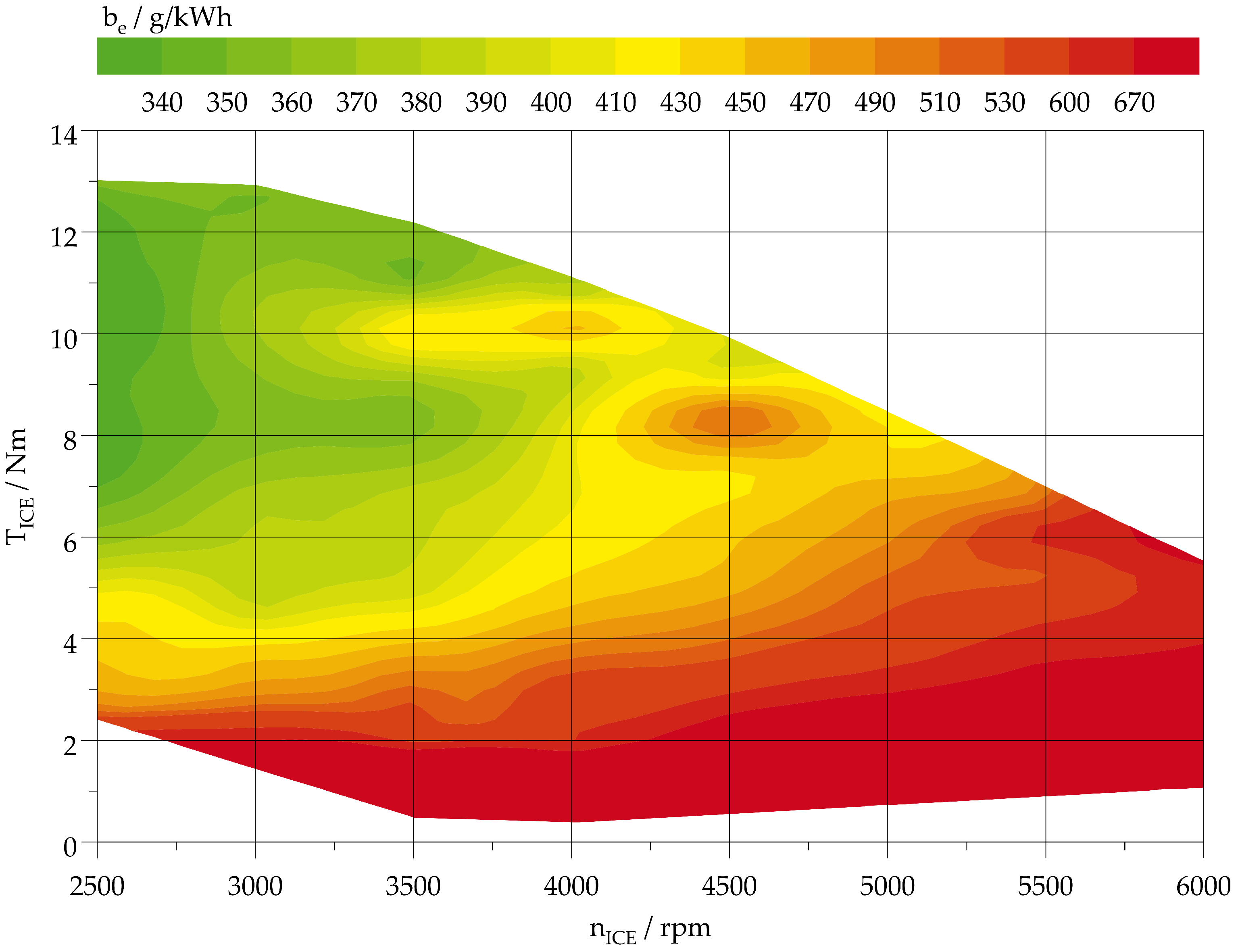
To experimentally evaluate the feasibility of the electrified planetary gear set (ePGS) hybrid powertrain, a demonstrator vehicle was built. To avoid restrictions of available package space, it was decided to develop the vehicle on the basis of a go-kart instead of a scooter. This offers significantly more space for the integration of standard off-the-shelf components. In comparison with a scooter, the ICE installed is a GX200 by Honda Motor Co., Ltd., Tokyo, Japan. The standard version offers a maximum torque of
= 13
and a power output of
= 4.3
at a rotational speed
= 3600
[
21]. To operate the engine at higher speeds, stronger valve springs were installed and the speed limiter was removed. Thus, the ICE can be used up to
= 6000
. Since the carburator was not modified, the maximum available power increases only slightly to
= 4.7
at
= 4500
. The load of the combustion engine is controlled by a throttle valve with bowden cable. While the throttle position is only measured, electronic influence is not possible. Thus, the load control of the ICE is carried out exclusively by the driver.
Figure 3 shows the fuel consumption map of the ICE, which was measured at a test bench at the Center for mobile Propulsion at RWTH Aachen University. Below
= 2500
, the torque fluctuation of the ICE caused operation and measurement problems in this test bench configuration, so lower speeds were not measured.
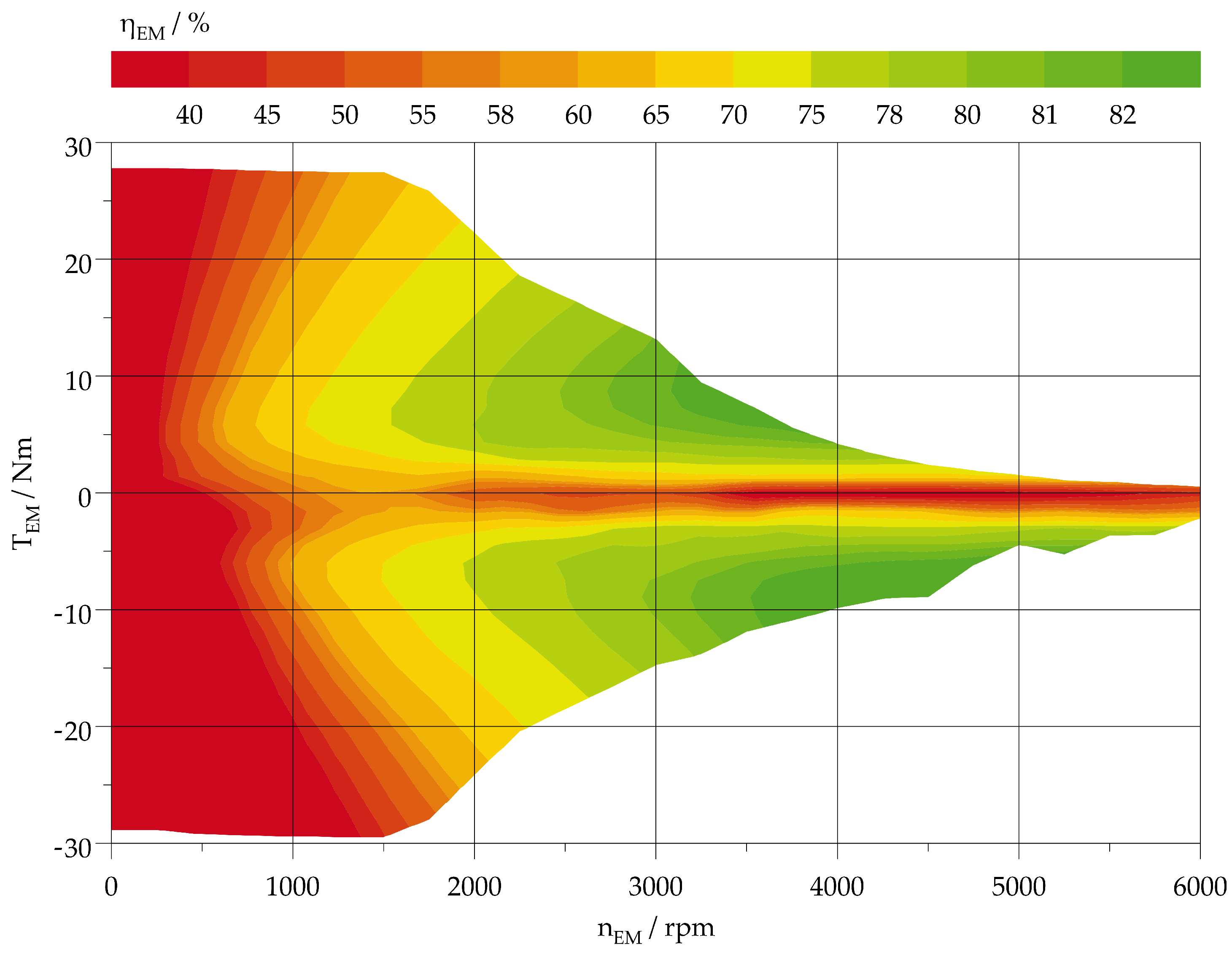
The electric drive consists of an asynchronous machine and a matching inverter with a DC link voltage of
= 48
. It delivers a maximum torque of
= 28
in motoring and
= 29.5
in generating operations. The rated power of the air-cooled machine is
= 2.6
, with a peak power of
= 5.9
available for a short time.
Figure 4 shows the measured efficiency map from DC power to mechanical power of the electric motor used.
The battery is typically used in automotive hybrid applications with a lithium ion cell chemistry. It has a capacity of 8 Ah and provides sufficient current to operate the electric motor at maximum power. However, long driving in full electric mode is limited by the battery capacity. The planetary gear set is a standard off-the-shelf component with a fixed carrier train ratio of
. Although it is not explicitly designed for three-shaft operation, it has proven to be robust and reliable in practice. The ratings, with a maximum output speed of
= 6000
and a maximum torque capacity of
T = 70
, are sufficient for the powertrain. Due to its single-stage design, the PGS has a high peak efficiency of about
[
22]. The one-way clutch and the centrifugal clutch are standard components as well. The one-way clutch can support a torque of more than
= 80
and can be used at speeds up to
n = 6000
. The selected centrifugal clutch can transmit a torque of
T = 30
at an engagement speed of
n = 1900
. This corresponds to a vehicle speed of
v = 35
, defining the transition from VRM operation to PDM operation. Full electric driving is therefore only possible below this speed, since automatic engagement of the centrifugal clutch would crank the engine. The control unit is a Vera 4.0 compact from VEMAC GmbH & Co. KG (Aachen, Germany). It provides sufficient I/O functionalities as well as an interface for model-based software development with Matlab-Simulink (2018b, Mathworks, Natick, MA, USA), which significantly simplifies the development of the prototype software.
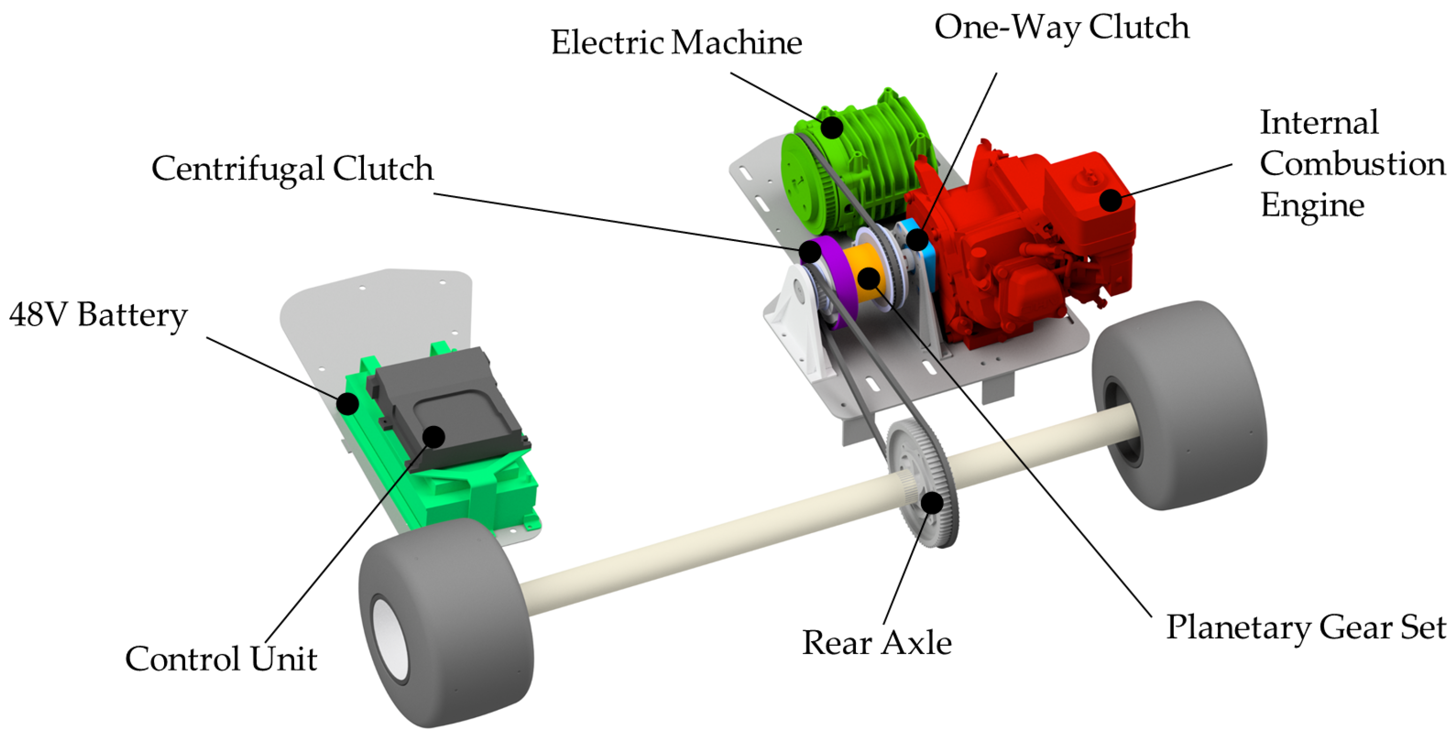
Figure 5 shows the powertrain integration in the prototype vehicle. The PGS is directly mounted to the ICE crankshaft and the one-way clutch is located between the PGS and the ICE. Due to package reasons, the electric motor and the rear axle are connected via tooth belt drives. While the tooth belt drive between the electric motor and the centrifugal clutch has a transmission ratio of
= 0.86 to comply with Equation (2) and support the torque of the ICE, the transmission ratio to the rear axle is
= 2.9 to reduce the rear axle speed to reasonable vehicle speeds and increase the traction force. The inverter is mounted on top of the electric motor to reduce the length of the three-phase wires and improve electromagnetic compatibility. To balance the weight distribution, additional components such as the battery, the control unit and electrics are located on the other side of the driver seat. The simulated maximum tractive force characteristics based on the powertrain designed for this vehicle with all components mentioned is described in
Section 5. In VRM, when the clutch is open, a constant tractive force of just under
= 720
is applied. From the point at which the clutch speed is exceeded, the tractive force decreases almost linearly with speed and, at the maximum speed
v = 80
, is expected to be around
F = 250
.
4. Control Strategy
As already explained in
Section 2, the ePGS hybrid powertrain presented has two fundamentally different operating modes. While the speed of the ICE can be varied in the lower speed range, a torque split between the ICE and the EM, as known from most parallel hybrid topologies, is not possible because the torque at the output directly depends on the torque of the ICE and EM according to Equation (
2).
In terms of the operating strategy, hybrid functions can be controlled solely by the electric motor. To achieve the lowest specific fuel consumption, the speed of the combustion engine is shifted into the range where the specific fuel consumption is minimal for the requested torque. As shown in
Figure 3, this is usually the case at
= 2500
. As this is not necessarily the point of neutral charge balance, the battery may be either charged or discharged. Intended charging of the battery is possible by pushing the speed of the electric motor into the negative range, which causes it to operate as a generator and leads to an increased ICE speed. To discharge the battery, the electric motor is shifted to the motoring operation, which reduces the speed of the ICE. Recuperation is possible in three-shaft operation, but the maximum achievable recuperation torque is limited by the drag torque of the combustion engine. A further increase in the generating torque could lead to acceleration or possibly overspeeding of the ICE.
Purely electric driving is only possible due to the one-way clutch in the low speed range before the centrifugal clutch is engaged. As a result, the wheel torque in electric operation is at least as high as that in hybrid operation, because the torque that needs to be supported in VRM equals the maximum motoring torque during electric drive. The EM speed is then proportional to the vehicle speed.
As soon as the engagement speed is exceeded, the centrifugal clutch locks the planetary gearset. Subsequently, speed conversion in the PGS is no longer possible. The ICE and EM directly drive the output. This enables one to combine the torque of both the ICE and EM. A shift in the operating point of the combustion engine is only possible by adjusting the torque and is comparable with parallel hybrid powertrains. Due to the mechanical coupling of the ICE, EM and drive shaft, the recuperation potential is not limited by the drag torque of the ICE anymore. Simultaneously, the engine is permanently dragged during recuperation, which reduces the maximum recuperation torque due to friction losses.
The transition to PDM operation is particularly challenging. In principle, this can take place both from electric driving and from hybrid operation. When the speed limit is reached, the centrifugal clutch begins to slip, drag launching the ICE in electric mode or equalising the speeds of the ICE and EM in hybrid mode. During the alignment of the shafts of the planetary gearset, one shaft is accelerated while the other shaft is decelerated. Due to the high inertia of the vehicle on the planet carrier, the noticeable torque loss during this process is comparably low. To minimise losses and even increase the driving comfort, the speed of the combustion engine and electric motor can be actively adjusted before the clutch engages. This reduces frictional losses and clutch wear, while a hard jerk can be avoided completely.
The use of a mechanical throttle valve reduces the system costs, but results in a battery state-of-charge (SOC)-dependent driveability. When the SOC is low, the battery is charged in VRM operation by adjusting the EM to the generating operation. This automatically increases the speed of the ICE, resulting in less filling of the engine and, thus, lower output torque at the same throttle position. In PDM, a low battery SOC is compensated by a higher generative torque from the EM. Just like in VRM, this reduces the output torque and forces the driver to open the throttle manually.
An electric torque assist function can be implemented, although it only makes sense at the maximum throttle angle. For this purpose, the speed of the combustion engine is shifted into the maximum torque range in VRM. In PDM, more torque at the drive shaft can be generated by increasing the torque of the electric motor.
In summary, the EM is used as the single active actuator in the system. In VRM, the speed control of the EM sets the BSFC optimal ICE speed in order to further minimise fuel consumption. During the transition from VRM to PDM, the EM actively synchronises the shaft speeds of the PGS to ensure minimal friction losses, reduced clutch wear and increase driving comfort.
5. Validation
For the validation of the functional demonstrator and to proove the functionality of the novel powertrain, different driving scenarios were analysed with the vehicle. The operating strategy implemented is essentially the same as that proposed in
Section 4. However, speed control in VRM is challenging because the inverter used to operate the electric motor does not support internal speed control, and control via CAN bus has proved to be too slow. For this reason, the supporting torque is pre-controlled in VRM. The torque is adapted to the throttle angle set by the driver and thus follows the torque provided by the combustion engine. However, this approach does not provide maximum acceleration.
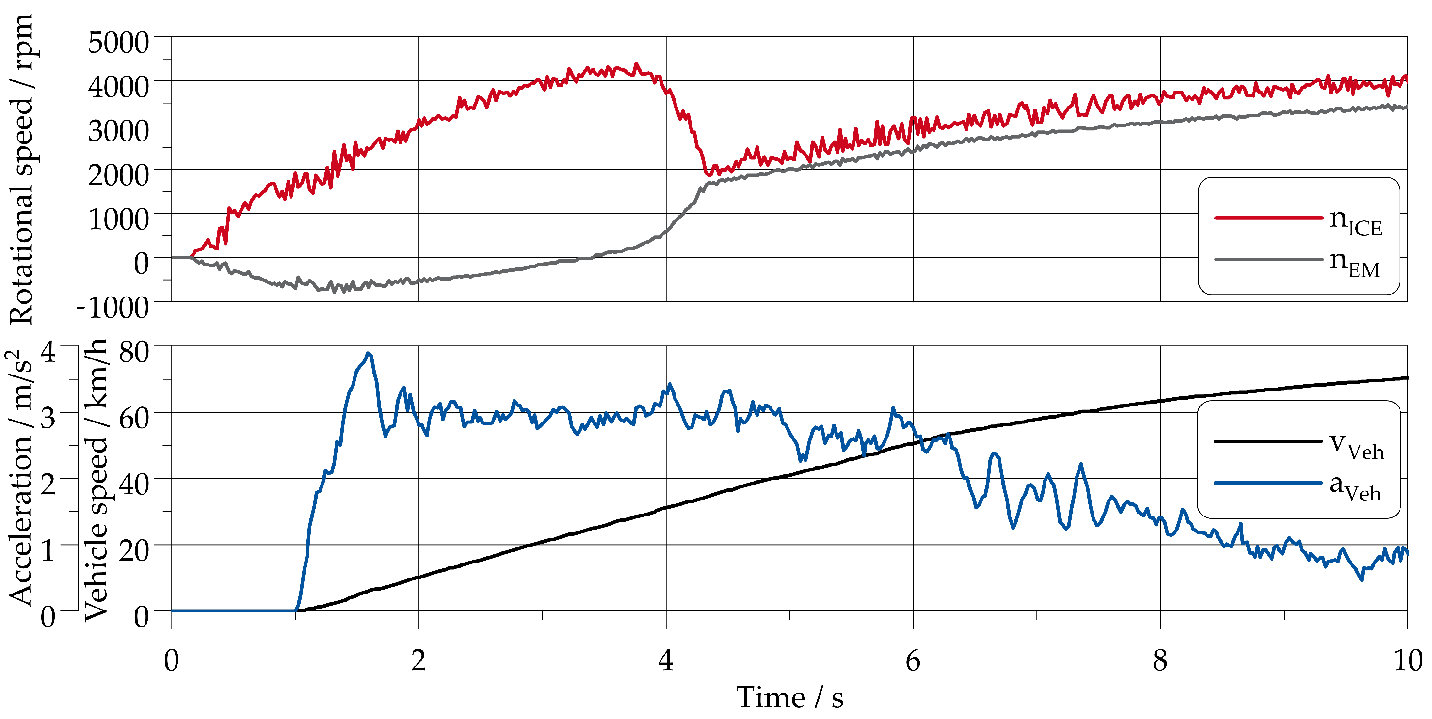
Figure 6 shows the speeds of the electric motor and the combustion engine during full-load acceleration. At low speeds, the electric motor rotates in the opposite direction to the combustion engine. Between a vehicle speed
= 28
and
v = 35
, the clutch begins to engage and equalises the speeds of the PGS shafts. Above that speed region, the clutch is completely locked. The acceleration from 0 to 60
is completed in 6.2 s. In the shown scenario (
Figure 6), the synchronisation of the PGS shafts is solely performed by the centrifugal clutch and not via the control strategy of the electric motor. The stable speed curve shows that even in the worst configuration with purely mechanical synchronisation, the transition from VRM to PDM takes place smoothly and without noticeable jerk.
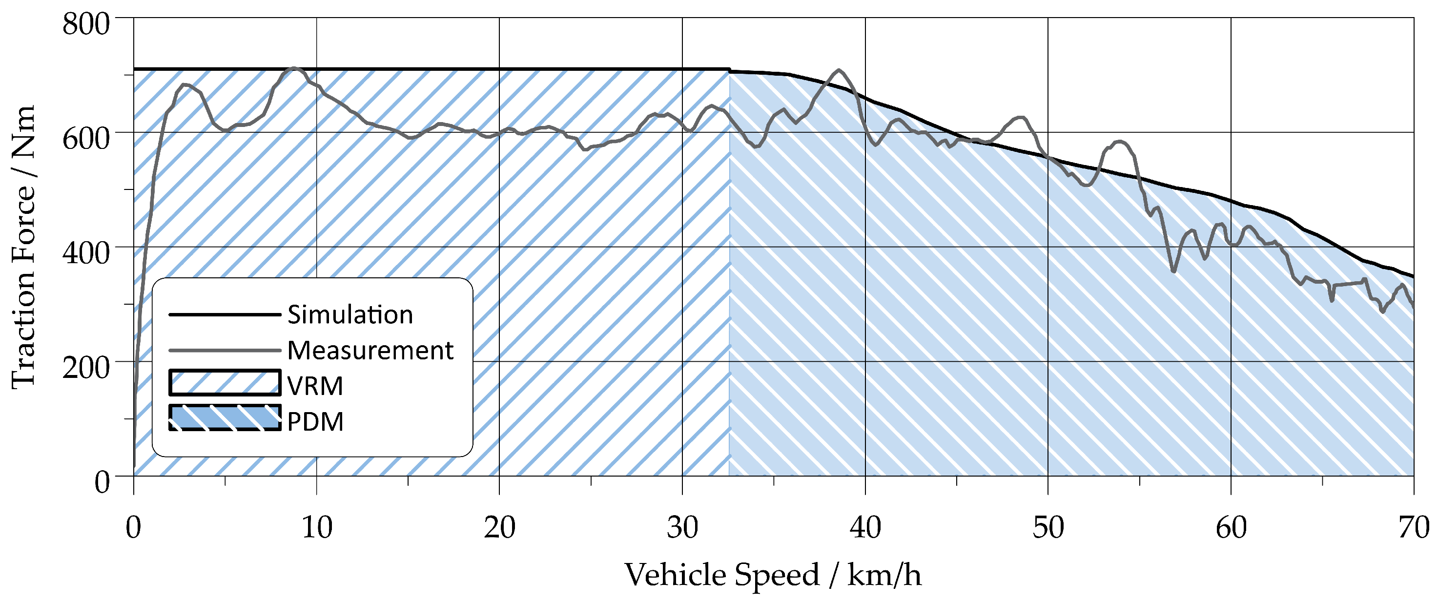
Figure 7 shows the tractive force characteristics of the measured prototype and the simulation results of the implemented powertrain. The plot exhibits that the tractive force characteristics of the measurement well match the simulation. This traction force simulation consists of the measured torque characteristics of the electric motor, ICE and centrifugal clutch as well as the kinematics of the planetary gear set combined with a basic driving resistance and friction loss model. The deviation in VRM can be explained with the non-optimal engine speed due to challenges in the EM control and losses in the planetary gear set. In PDM, the simulation matches the measurement more accurately, since the EM can be controlled with a simple torque request which adds to the ICE torque. The tractive force diagram shows that the drive train is able to deliver constant torque during the complete velocity range from
= 0
until
v = 35
is reached.
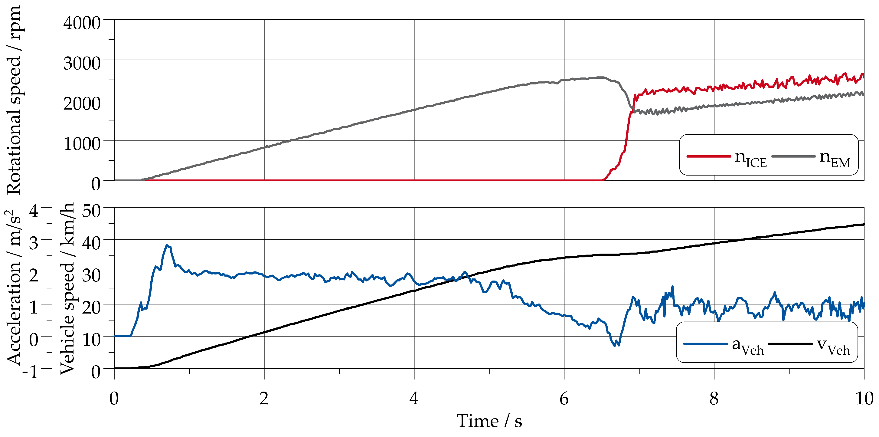
In
Figure 8, the speed of the electric motor and of the ICE, as well as the vehicle velocity and the acceleration for a pure electric launch in part load from standstill, are shown. At around six seconds after starting, at
= 35
, the ICE is automatically cranked due to the locking of the centrifugal clutch. The rapid increase in the ICE speed indicates a smooth and immediate engine start, causing a slight drop in acceleration. The acceleration, however, already decreases before the centrifugal clutch is locked. This decrease is related to field weakening of the EM beyond
= 2000
. Accordingly, the acceleration drop during the transition form VRM to PDM is smooth and small. After the engine is started, the powertrain is operated in parallel hybrid drive and the speeds of the ICE and EM are proportional to the vehicle velocity. Since torque addition is then possible, the acceleration increases slightly, although the requested torque in this scenario was only at 60% of the maximum torque. In summary, the test scenarios show that the powertrain meets the simulation results and shows a smooth and comfortable driving behaviour and good performance.


